1
Comtech EF Data is an
AS9100 Rev B / ISO9001:2000 Registered Company
DMD20/DMD20LBST
Universal Satellite Modem
Installation and Operation Manual
IMPORTANT NOTE: The information contained in this document supersedes all previously
published information regarding this product. This manual is subject to change without prior notice.
Part Number MN-DMD20-20LBST
Revision 14
Errata A for MN-DMD20-20LBST Rev 14
Comtech EF Data Documentation Update
Subject:
Errata Part Number:
PLM CO Number:
Comments:
ER-DMD20LBS-EA14
Chapter 7, Technical Specifications
ER-DMD20LBS-EA14
(Errata documents are not subject to revision.)
C-0026230
See attached page(s). The new information will be included in the next released
revision of the manual.
Rev -
PLM C-0026230
Blank Page
ER-DMD20LBS-EA14
Rev -
PLM C-0026230
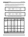
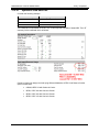
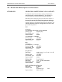
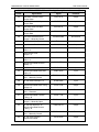
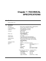
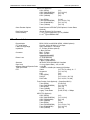
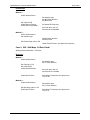
Chapter 7. TECHNICAL
SPECIFICATIONS
7.1
Data Rates
Refer to Section 7.18.
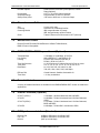
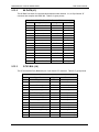
7.2
Modulator
Modulation
IF Tuning Range
L-Band Tuning Range
Impedance
Connector
Return Loss
Output Power
Output Stability
Output Spectrum
Spurious
On/Off Power Ratio
Scrambler
FEC
BPSK, QPSK, and OQPSK (8PSK, 16QAM Optional)
50 to 90, 100 to 180 MHz in 1 Hz Steps
950 to 2050 MHz in 1 Hz Steps
IF, 75-Ohm (50-Ohm Optional)
L-Band, 50-Ohm
BNC, 75-Ohm
SMA, 50-Ohm, L-Band or
N-type, 50-Ohm LBST
IF, 20 dB Minimum
L-Band, 14 dB Minimum
0 to -25 dB
IF: ±0.5 dB Over Time and Temperature
L-Band: ±1.0 dB Over Time and Temperature
Meets IESS 308/309/310 Power Spectral Mask
-50 dBc In-Band (50 to 90 MHz, 100 to 180 MHz,
950 to 2050 MHz)
-45 dBc Out-of-Band
>60 dB
CCITT V.35 or IBS (Others Optional)
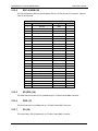
Viterbi,
{1/2, 3/4, 7/8, None} K = 7
Sequential
{1/2, 3/4, 7/8}
CSC
{3/4}
Trellis (8PSK)
{2/3}
DVB VIT
{1/2, 2/3, 3/4, 5/6, 7/8}
DVB Trellis
{2/3, 3/4, 5/6, 7/8, 8/9}
Turbo Product Code (Optional) – (SuperCard ONLY)
Turbo (BPSK)
{21/44,5/16}
Turbo (OQPSK/QPSK)
{1/2, 3/4, 7/8}
Turbo (8PSK)
{3/4, 7/8}
Turbo (16QAM)
{3/4, 7/8}
Legacy Turbo Rates
{0.495, 0.793} < 5Mbps
MN-DMD20-20LBST Revision 14
ER-DMD20LBS-EA14 Rev -
7–1
DMD20/20LBST Universal Satellite Modem
Technical Specifications
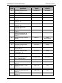
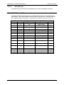
LDPC/TPC (Optional)
LDPC (BPSK)
LDPC (OQPSK/QPSK)
LDPC (8PSK/8QAM)
LDPC (16QAM)
Turbo (BPSK)
Turbo (QPSK/OQPSK)
Turbo (8QAM/8PSK)
Turbo (16QAM)
Outer Encoder Options
{21/44}
{1/2, 2/3, 3/4, 7/8}
{2/3, 3/4, 7/8}
{3/4, 7/8}
Reed-Solomon INTELSAT (DVB Optional, Custom Rates
Optional)
Internal, External, Rx Recovered
-6
-8
1 x 10 Typical (Optional to 5 x 10 ) DMD20
-8
5 x 10 Typical DMD20 LBST
Data Clock Source
Internal Stability
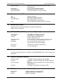
7.3
{1/2}
{1/2, 2/3, 3/4}
{2/3, 3/4}
{3/4}
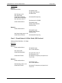
Demodulator
Demodulation
IF Tuning Range
L-Band Tuning Range
Impedance
Connector
Return Loss
Spectrum
Input Level
Adjacent Channel Rejection Ratio
Total Input Power
FEC
BPSK, QPSK, and OQPSK (8PSK, 16QAM Optional)
50 to 90, 100 to 180 MHz in 1 Hz Steps
950 to 2050 MHz in 1 Hz Steps
IF, 75-Ohm (50-Ohm optional)
L-Band, 50-Ohm
BNC - 75 Ohm
SMA - 50 Ohm
N-type 50-Ohm LBST
IF, 20 dB Minimum
SMA, 50-Ohm, L-Band
L-Band, 14 dB Minimum
INTELSAT IESS 308/309/310 Compliant
10 x log (Symbol Rate) - 100, ±12 dB
>+10 dBc
-10 dBm or +40 dBc (the Lesser) @ 256 Kbps
Viterbi
{1/2, 3/4, 7/8, None} K = 7
Sequential
{1/2, 3/4, 7/8}
CSC
{3/4}
Trellis (8PSK)
{2/3}
DVB VIT
{1/2, 2/3, 3/4, 5/6, 7/8}
DVB Trellis
{2/3, 3/4, 5/6, 7/8, 8/9}
Turbo Product Code (Optional) – (SuperCard ONLY)
Turbo (BPSK)
{21/44,5/16}
Turbo (OQPSK/QPSK)
{1/2, 3/4, 7/8}
Turbo (8PSK)
{3/4, 7/8}
Turbo (16QAM)
{3/4, 7/8}
Legacy Turbo Rates
{0.495, 0.793} < 5Mbps
LDPC/TPC (Optional)
LDPC (BPSK)
LDPC (OQPSK/QPSK)
LDPC (8PSK/8QAM)
LDPC (16QAM)
Turbo (BPSK)
Turbo (QPSK/OQPSK)
Turbo (8QAM/8PSK)
Turbo (16QAM)
MN-DMD20-20LBST Revision 14
ER-DMD20LBS-EA14 Rev -
{1/2}
{1/2, 2/3, 3/4}
{2/3, 3/4}
{3/4}
{21/44}
{1/2, 2/3, 3/4, 7/8}
{2/3, 3/4, 7/8}
{3/4, 7/8}
7–2
DMD20/20LBST Universal Satellite Modem
Decoder Options
Reed-Solomon INTELSAT (DVB Optional, Custom
Rates Optional)
CCITT V.35 or IBS (Others Optional)
Programmable ±1 kHz to ± 255 kHz
100 msec to 6000 sec. in 100 msec Steps
Descrambler
Acquisition Range
Sweep Delay Value
7.4
Plesiochronous Buffer
Size
Centering
Centering Modes
Clock
7.5
Technical Specifications
0 msec to 64 msec
Automatic on Underflow/Overflow
IBS: Integral Number of Frames
IDR: Integral Number of Multi Frames
Transmit, External, Rx Recovered or SCT (Internal)
Monitor and Control
Remote RS-485/Terminal RS-232/Ethernet 10 Base-T/Web Browser,
DMD15 Protocol Compatible
7.6
DMD20/DMD20 LBST Drop and Insert (Optional)
Terrestrial Data
Line Coding
Framing
Time Slot Selection
Time Slots
Data Rates
Efficient D&I
Time Slots
7.7
1.544 Mbps or 2.048 Mbps, G.732/733
AMI or B8ZS for T1 and HDB3 for E1
D4, ESF and PCM-30 (PCM-30C) or
PCM-31 (PCM- 31C) for E1
n x 64 Contiguous or Arbitrary Blocks for Drop or Insert.
TS1, 2, 3, 4, 5, 6, 8, 10, 12, 15, 16, 20, 24, 30, 31
64, 128, 192, 256, 320, 384, 512, 640,
768, 960, 1024, 1280, 1536, 1920 Kbps
Closed Network, Satellite Overhead 0.4%
1-31 Any combination
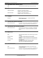
Terrestrial Interfaces
A variety of standard interfaces are available for the DMD20/DMD20 LBST modem in stand-alone
applications.
7.8
IDR/ESC Interface (Optional)
G.703 T1 (DSX1)
G.703 E1
G.703 T2 (DSX2)
G.703 E2
7.9
1.544 Mbps, 100-Ohm Balanced, AMI and B8ZS
2.048 Mbps, 75-Ohm Unbalanced and 120-Ohm Balanced,
HDB3
6.312 Mbps, 75-Ohm Unbalanced and 110-Ohm Balanced,
B8ZS and B6ZS
8.448 Mbps, 75-Ohm BNC, Unbalanced, HDB3
IBS/Synchronous Interface (Standard)
RS-422/-530
ITU V.35
RS-232
MN-DMD20-20LBST Revision 14
All Rates, Differential, Clock/Data, DCE
All Rates, Differential, Clock/Data, DCE
(DCE up to 200 Kbps)
ER-DMD20LBS-EA14 Rev -
7–3
DMD20/20LBST Universal Satellite Modem
Technical Specifications
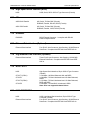
7.10 High-Speed Serial Interface (HSSI)
HSSI:
HSSI, Serial, 50-Pin SCSI-2 Type Connector (Female)
7.11 ASI
ASI/RS-422 Parallel:
ASI, Serial, 75-Ohm BNC (Female)
DVB/M2P, Parallel, RS-422, DB-25 (Female)
ASI/LVDS Parallel:
ASI, Serial, 75-Ohm BNC (Female)
DVB/M2P, Parallel, LVDS, DB-25 (Female)
7.12 DVB/M2P
DVB/M2P:
DB-25 Female Connector. It complies with RS-422
Electrical Specifications.
7.13 Ethernet Data Interface (Optional)
Ethernet Data Interface
Four RJ-45, Auto-Crossover, Auto-Sensing, 10/100 Ethernet
Data Ports. Complies with IEEE 802.3 and IEEE 802.3u.
7.14 Gigi Ethernet Data Interface (Optional)
Ethernet Data Interface
Three RJ-45, Auto-Crossover, Auto-Sensing, 10/100/1000
Ethernet Data Ports. Complies with IEEE 802.3 and IEEE
802.3u.
7.15 HSSI / G703
HSSI
G.703 T1 (DSX1)
G.703 E1
G.703 T2 (DSX2)
G.703 E2
High-Speed Serial Interface, 50-pin SCSI-2 Type Connector
(Female)
1.544 Mbps, 100-Ohm Balanced, AMI and B8ZS
2.048 Mbps, 75-Ohm Unbalanced and 120-Ohm Balanced,
HDB3
6.312 Mbps, 75-Ohm Unbalanced and 110-Ohm Balanced,
B8ZS and B6ZS
8.448 Mbps, 75-Ohm BNC, Unbalanced, HDB3
Note: Does not support backward alarms
7.16 HSSI /ETHERNET
HSSI
Ethernet Data Interface
MN-DMD20-20LBST Revision 14
HSSI, High-Speed Serial Interface, 50-pin SCSI-2 Type
Connector (Female)
Four RJ-45, Auto-Crossover, Auto-Sensing, 10/100 Ethernet
Data Ports. Complies with IEEE 802.3 and IEEE 802.3u.
ER-DMD20LBS-EA14 Rev -
7–4
DMD20/20LBST Universal Satellite Modem
Technical Specifications
7.17 Environmental
Prime Power
Operating Temperature
Storage Temperature
100 to 240 VAC, 50 to 60 Hz, 40 Watts Maximum
48 VDC (Optional)
0 to 50°C, 95% Humidity, Non-Condensing
-20 to 70°C, 99% humidity, Non-Condensing
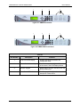
7.18 Physical
Size
Weight
DMD20
DMD20 LBST
19” W x 16” D x 1.75” H
(48.26 x 40.64 x 4.45 cm)
6.5 Pounds (3.0 Kg)
19” W x 19.25” D x 1.75” H
(48.26 x 48.89 x 4.45 cm)
8.5 pounds (3.83 kg)
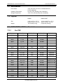
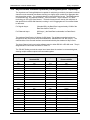
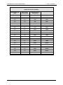
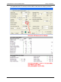
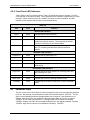
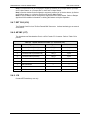
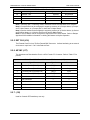
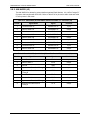
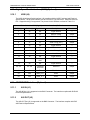
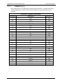
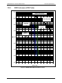
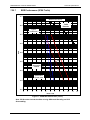
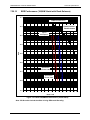
7.19 DMD20/DMD20 LBST Data Rate Limits
7.19.1
Non-DVB
Modulation
Code Rate
Min Data Rate
Max Data Rate
BPSK
NONE
4800
10000000
BPSK
VIT 1/2
2400
5000000
BPSK
VIT 3/4
3600
7500000
BPSK
VIT 7/8
4200
8750000
BPSK
SEQ 1/2
2400
2048000
BPSK
SEQ 3/4
3600
2048000
BPSK
CSEQ 3/4
3600
2048000
BPSK
SEQ 7/8
4200
2048000
BPSK
TPC 21/44
2400
4772727
Supercard
BPSK
TPC .495
2376
4900000
Supercard
BPSK
TPC .793
3806
6300000
Supercard
BPSK
TPC 3/4
4100
6990000
Supercard
BPSK
TPC 7/8
4200
8200000
Supercard
BPSK
TPC 21/44
18000
477000
LDPC/TPC Card
BPSK
LDPC 1/2
18000
5000000
LDPC/TPC Card
QPSK
NONE
9600
20000000
QPSK
VIT 1/2
4800
10000000
QPSK
VIT 3/4
7200
15000000
QPSK
VIT 7/8
8400
17500000
QPSK
SEQ 1/2
4800
2048000
QPSK
SEQ 3/4
7200
2048000
QPSK
CSEQ 3/4
7200
2048000
MN-DMD20-20LBST Revision 14
ER-DMD20LBS-EA14 Rev -
Option Card
7–5
DMD20/20LBST Universal Satellite Modem
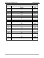
Technical Specifications
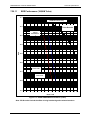
Modulation
Code Rate
Min Data Rate
Max Data Rate
QPSK
SEQ 7/8
8400
2048000
QPSK
TPC 1/2
4582
9545454
Supercard
QPSK
TPC 3/4
7200
15000000
Supercard
QPSK
TPC 7/8
8400
17500000
Supercard
QPSK
TPC .495
4752
6312000
Supercard
QPSK
TPC .793
7612
6312000
Supercard
QPSK
LDPC 1/2
18000
10000000
LDPC/TPC Card
QPSK
LDPC 2/3
24000
13333333
LDPC/TPC Card
QPSK
LDPC 3/4
27000
15000000
LDPC/TPC Card
QPSK
TPC 1/2
18000
9545400
LDPC/TPC Card
QPSK
TPC 3/4
27000
15000000
LDPC/TPC Card
QPSK
TPC 7/8
31500
17500000
LDPC/TPC Card
OQPSK
NONE
9600
20000000
OQPSK
VIT 1/2
4800
10000000
OQPSK
VIT 3/4
7200
15000000
OQPSK
VIT 7/8
8400
17500000
OQPSK
SEQ 1/2
4800
2048000
OQPSK
SEQ 3/4
7200
2048000
OQPSK
SEQ 7/8
8400
2048000
OQPSK
TPC 1/2
4582
9545454
Supercard
OQPSK
TPC 3/4
7200
15000000
Supercard
OQPSK
TPC 7/8
8400
17500000
Supercard
OQPSK
TPC .495
4752
6312000
Supercard
OQPSK
TPC .793
7612
6312000
Supercard
OQPSK
LDPC 1/2
18000
10000000
LDPC/TPC Card
OQPSK
LDPC 2/3
24000
13333333
LDPC/TPC Card
OQPSK
LDPC 3/4
27000
15000000
LDPC/TPC Card
OQPSK
TPC 1/2
18000
9545400
LDPC/TPC Card
OQPSK
TPC 3/4
27000
15000000
LDPC/TPC Card
OQPSK
TPC 7/8
31500
17500000
LDPC/TPC Card
8PSK
TRE 2/3
9600
20000000
8PSK
TPC 3/4
10800
20000000
Supercard
8PSK
TPC 7/8
12600
20000000
Supercard
8PSK
TPC .495
9504
6312000
Supercard
8PSK
TPC .793
15225
6312000
Supercard
8PSK/8QAM
LDPC 2/3
36000
20000000
LDPC/TPC Card
MN-DMD20-20LBST Revision 14
ER-DMD20LBS-EA14 Rev -
Option Card
7–6
DMD20/20LBST Universal Satellite Modem
Technical Specifications
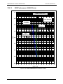
Modulation
Code Rate
Min Data Rate
Max Data Rate
Option Card
8PSK/8QAM
LDPC 3/4
40500
20000000
LDPC/TPC Card
8PSK
TPC 3/4
40000
20000000
LDPC/TPC Card
8PSK
TPC 7/8
48000
20000000
LDPC/TPC Card
16QAM
VIT 3/4
14400
20000000
16QAM
VIT 7/8
16840
20000000
16QAM
TPC 3/4
1440
20000000
Supercard
16QAM
TPC 7/8
16800
20000000
Supercard
16QAM
TPC .495
9504
6312000
Supercard
16QAM
TPC .793
15225
6312000
Supercard
16QAM
TPC 3/4
54000
20000000
LDPC/TPC Card
16QAM
TPC 7/8
63000
20000000
LDPC/TPC Card
16QAM
LDPC 3/4
54000
20000000
LDPC/TPC Card
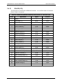
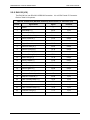
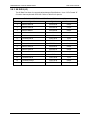
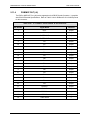
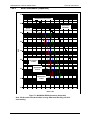
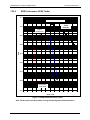
7.19.2
DVB
187 Mode
Modulation
Code Rate
Min Data Rate
Max Data Rate
BPSK
VIT 1/2
2400
4583333
BPSK
VIT 2/3
2934
6111111
BPSK
VIT 3/4
3300
6875000
BPSK
VIT 5/6
3667
7638888
BPSK
VIT 7/8
3850
8020833
QPSK
VIT 1/2
4400
9166666
QPSK
VIT 2/3
5867
12222222
QPSK
VIT 3/4
6600
13750000
QPSK
VIT 5/6
7334
15277777
QPSK
VIT 7/8
7700
16041666
8PSK
TRE 2/3
8800
18333333
8PSK
TRE 5/6
11000
20000000
8PSK
TRE 8/9
11734
20000000
16QAM
TRE 3/4
13200
20000000
16QAM
TRE 7/8
15400
20000000
MN-DMD20-20LBST Revision 14
ER-DMD20LBS-EA14 Rev -
7–7
DMD20/20LBST Universal Satellite Modem
Technical Specifications
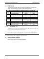
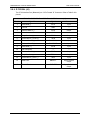
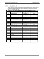
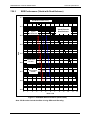
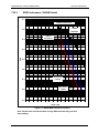
188 Mode
Modulation
Code Rate
Min Data Rate
Max Data Rate
BPSK
VIT 1/2
2400
4607843
BPSK
VIT 2/3
2950
6143790
BPSK
VIT 3/4
3318
6911764
BPSK
VIT 5/6
3687
7679738
BPSK
VIT 7/8
3871
8063725
QPSK
VIT 1/2
4424
9215686
QPSK
VIT 2/3
5899
12287581
QPSK
VIT 3/4
6636
13823529
QPSK
VIT 5/6
7373
15359477
QPSK
VIT 7/8
7742
16127450
8PSK
TRE 2/3
8848
18431372
8PSK
TRE 5/6
11059
20000000
8PSK
TRE 8/9
11797
20000000
16QAM
TRE 3/4
13271
20000000
16QAM
TRE 7/8
15483
20000000
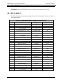
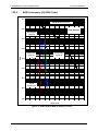
204 Mode
Modulation
Code Rate
Min Data Rate
Max Data Rate
BPSK
VIT 1/2
2400
5000000
BPSK
VIT 2/3
3200
6666666
BPSK
VIT 3/4
3600
7500000
BPSK
VIT 5/6
4000
8333333
BPSK
VIT 7/8
4200
8750000
QPSK
VIT 1/2
4800
10000000
QPSK
VIT 2/3
6400
13333333
QPSK
VIT 3/4
7200
15000000
QPSK
VIT 5/6
8000
16666666
QPSK
VIT 7/8
8400
17500000
8PSK
TRE 2/3
9600
20000000
8PSK
TRE 5/6
12000
20000000
8PSK
TRE 8/9
12800
20000000
16QAM
TRE 3/4
14400
20000000
16QAM
TRE 7/8
16800
20000000
MN-DMD20-20LBST Revision 14
ER-DMD20LBS-EA14 Rev -
7–8
DMD20/20LBST Universal Satellite Modem
Technical Specifications
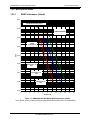
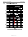
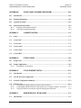
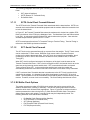
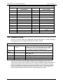
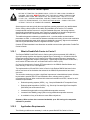
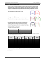
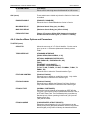
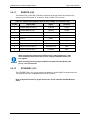
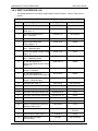
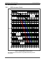
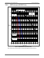
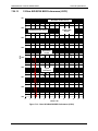
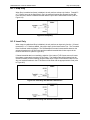
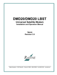
7.20 BER Specifications
7.20.1
BER Performance (Viterbi)
1E-1
B/O/QPSK Uncoded Theory
1E-2
Viterbi Decoder
1E-3
Typical
Performance
BER
1E-4
1E-5
1E-6
Specification 1/2
Rate
Specification 3/4
Rate
1E-7
Specification 7/8
Rate
1E-8
1E-9
0
1
2
3
4
5
6
7
8
9
10
11
12
Eb/No in dB
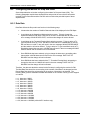
Figure 7-1 DMD20/20LBST B/O/QPSK BER Performance (Viterbi)
Note: Eb/No values include the effect of using Differential Decoding and V.35 descrambling.
MN-DMD20-20LBST Revision 14
ER-DMD20LBS-EA14 Rev -
7–9
DMD20/20LBST Universal Satellite Modem
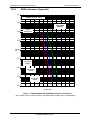
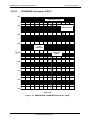
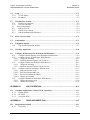
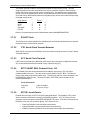
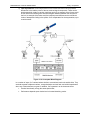
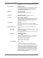
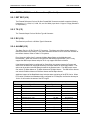
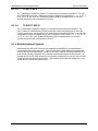
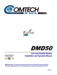
7.20.2
Technical Specifications
BER Performance (Sequential)
1E-1
B/O/QPSK Uncoded Theory
1E-2
Sequential
Decoder
Typical
Performance
1E-3
BER
1E-4
1E-5
1E-6
Specification
1/2 Rate
1E-7
Specification
3/4 Rate
1E-8
1E-9
Specification
7/8 Rate
0
1
2
3
4
5
6
7
8
9
10
11
12
Eb/No in dB
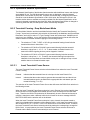
Figure 7-2 DMD20/20LBST B/O/QPSK BER Performance (Sequential)
Note: Eb/No values include the effect of using Differential Decoding and V.35 descrambling.
MN-DMD20-20LBST Revision 14
ER-DMD20LBS-EA14 Rev -
7–10
DMD20/20LBST Universal Satellite Modem
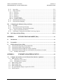
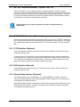
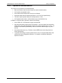
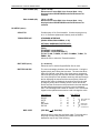
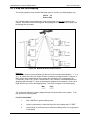
7.20.3
Technical Specifications
BER Performance (Viterbi with Reed-Solomon)
1E-1
B/O/QPSK Uncoded Theory
1E-2
Typical
Performance
Viterbi Decoder Reed
Solomon
1E-3
BER
1E-4
1E-5
1E-6
Specification
1/2 Rate
1E-7
Specification
7/8 Rate
Specification
3/4 Rate
1E-8
1E-9
0
1
2
3
4
5
6
7
8
9
10
11
12
Eb/No in dB
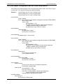
Figure 7-3 DMD20/20LBST B/O/QPSK BER Performance (Viterbi w/R-S)
Note: Eb/No values include the effect of using Differential Decoding.
MN-DMD20-20LBST Revision 14
ER-DMD20LBS-EA14 Rev -
7–11
DMD20/20LBST Universal Satellite Modem
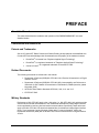
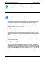
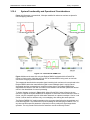
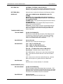
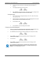
7.20.4
Technical Specifications
BER Performance (Turbo)
1E-1
B/O/QPSK Uncoded Theory
1E-2
Turbo Decoder
Typical
Performance
1E-3
BER
1E-4
1E-5
1E-6
1E-7
Specification
Turbo 0.495
1E-8
1E-9
Specification
Turbo 0.793
0
1
2
3
4
5
6
7
8
9
10
11
12
Eb/No in dB
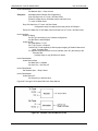
Figure 7-4 DMD20/20LBST B/O/QPSK BER Performance (Turbo)
MN-DMD20-20LBST Revision 14
ER-DMD20LBS-EA14 Rev -
7–12
DMD20/20LBST Universal Satellite Modem
7.20.5
Technical Specifications
BER Performance (8PSK Trellis)
1E-1
8PSK Uncoded Theory
Trellis
Decoder
1E-2
1E-3
Typical
Performance
BER
1E-4
1E-5
1E-6
Specification
2/3 Rate
1E-7
Specification
2/3 Rate w/RS
1E-8
1E-9
0
1
2
3
4
5
6
7
8
9
10
11
12
Eb/No in dB
Figure 7-5 DMD20/20LBST 8PSK BER Performance (Trellis)
Note: Eb/No values include the effect of using interleaving and maximum iterations.
MN-DMD20-20LBST Revision 14
ER-DMD20LBS-EA14 Rev -
7–13
DMD20/20LBST Universal Satellite Modem
7.20.6
Technical Specifications
BER Performance (8PSK Turbo)
1E-1
8PSK Uncoded Theory
1E-2
Turbo Decoder
Typical
Performance
1E-3
BER
1E-4
1E-5
1E-6
1E-7
1E-8
Specification
Turbo 0.793
1E-9
0
1
2
3
4
5
6
7
8
9
10
11
12
Eb/No in dB
Figure 7-6 DMD20/20LBST 8PSK BER Performance (Turbo)
Note: Eb/No values include the effect of using interleaving and maximum iterations
MN-DMD20-20LBST Revision 14
ER-DMD20LBS-EA14 Rev -
7–14
DMD20/20LBST Universal Satellite Modem
7.20.7
Technical Specifications
BER Performance (16QAM Viterbi)
1E-1
16QAM Uncoded Theory
Viterbi
Decoder
1E-2
1E-3
Typical
Performance
BER
1E-4
1E-5
1E-6
Specification
3/4 Rate
1E-7
Specification
7/8 Rate
1E-8
1E-9
0
1
2
3
4
5
6
7
8
9
10
11
12
13
14
15
Eb/No in dB
Figure 7-7 DMD20/20LBST 16QAM BER Performance (Viterbi)
Note: Eb/No values include the effect of using Differential Decoding and V.35 Descrambling.
MN-DMD20-20LBST Revision 14
ER-DMD20LBS-EA14 Rev -
7–15
DMD20/20LBST Universal Satellite Modem
7.20.8
Technical Specifications
BER Performance (16QAM Viterbi with Reed-Solomon)
1E-1
16QAM Uncoded Theory
1E-2
Viterbi Decoder Reed Solomon
Typical
Performance
1E-3
BER
1E-4
1E-5
1E-6
Specification
3/4 Rate w/RS
1E-7
Specification
7/8 Rate w/RS
1E-8
1E-9
0
1
2
3
4
5
6
7
8
9
10
11
12
13
14
15
Eb/No in dB
Figure 7-8 DMD20/20LBST 16QAM BER Performance (Viterbi w/R-S)
Note: Eb/No values include the effect of using Differential Decoding.
MN-DMD20-20LBST Revision 14
ER-DMD20LBS-EA14 Rev -
7–16
DMD20/20LBST Universal Satellite Modem
7.20.9
Technical Specifications
BER Performance (16QAM Turbo)
1E-1
16QAM Uncoded Theory
1E-2
Turbo Decoder
Typical
Performance
1E-3
BER
1E-4
1E-5
1E-6
Turbo 0.495
1E-7
Turbo 0.793
1E-8
1E-9
0
1
2
3
4
5
6
7
8
9
10
11
12
13
14
15
Eb/No in dB
Figure 7-9 DMD20/20LBST 16QAM BER Performance (Turbo)
Note: Eb/No values include the effect of using interleaving and maximum iterations.
MN-DMD20-20LBST Revision 14
ER-DMD20LBS-EA14 Rev -
7–17
DMD20/20LBST Universal Satellite Modem
7.20.10
Technical Specifications
BER Performance ((O)QPSK Turbo)
1E-1
B/O/QPSK Uncoded Theory
1E-2
Turbo Decoder
Specification
3/4 Rate
1E-3
1E-4
BER
Specification
1/2 Rate
Specification
7/8 Rate
1E-5
1E-6
1E-7
Typical
Performance
1E-8
1E-9
0
1
2
3
4
5
6
7
8
9
10
11
12
Eb/No in dB
Figure 7-10 DMD20/20LBST O/QPSK BER Performance (Turbo)
MN-DMD20-20LBST Revision 14
ER-DMD20LBS-EA14 Rev -
7–18
DMD20/20LBST Universal Satellite Modem
7.20.11
Technical Specifications
BER Performance (BPSK Turbo)
1E-1
B/O/QPSK Uncoded Theory
1E-2
Turbo Decoder
1E-3
BER
1E-4
Specification
21/44 Rate
1E-5
Specification
5/16 Rate
1E-6
1E-7
Typical
Performance
1E-8
1E-9
0
1
2
3
4
5
6
7
8
9
10
11
12
Eb/No in dB
Figure 7-11 DMD20/20LBST BPSK BER Performance (Turbo)
Note: BPSK TPC 5/16 available with PL/5051 Turbo Codec Hardware.
MN-DMD20-20LBST Revision 14
7–19
DMD20/20LBST Universal Satellite Modem
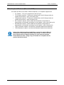
7.20.12
Technical Specifications
BER Performance (8PSK Turbo)
1E-1
8PSK Uncoded Theory
1E-2
Turbo Decoder
Specification 3/4
Rate
1E-3
Specification 7/8
Rate
1E-4
BER
Typical
Performance
1E-5
1E-6
1E-7
1E-8
1E-9
0
1
2
3
4
5
6
7
8
9
10
11
12
Eb/No in dB
Figure 7-12 DMD20/20LBST 8PSK BER Performance (Turbo)
MN-DMD20-20LBST Revision 14
ER-DMD20LBS-EA14 Rev -
7–20
DMD20/20LBST Universal Satellite Modem
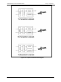
7.20.13
Technical Specifications
BER Performance (16QAM Turbo)
1E-1
16QAM Uncoded Theory
Turbo Decoder
1E-2
Specification 3/4
Rate
Specification 7/8
Rate
1E-3
1E-4
BER
Typical
Performance
1E-5
1E-6
1E-7
1E-8
1E-9
0
1
2
3
4
5
6
7
8
9
10
11
12
13
14
15
Eb/No in dB
Figure 7-13 DMD20/20LBST 16QAM BER Performance (Turbo)
MN-DMD20-20LBST Revision 14
ER-DMD20LBS-EA14 Rev -
7–21
DMD20/20LBST Universal Satellite Modem
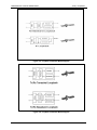
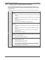
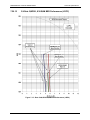
7.20.14
Technical Specifications
B/O/QPSK BER Performance (LDPC)
1E-1
B/O/QPSK Uncoded Theory
1E-2
LDPC Decoder
1E-3
Specification
1/2 Rate
Specification
2/3 Rate
1E-4
BER
Specification
3/4 Rate
1E-5
Typical
Performance
1E-6
1E-7
1E-8
1E-9
0
1
2
3
4
5
6
7
8
9
10
11
12
Eb/No in dB
Figure 7-14 – DMD20/20LBST B/O/QPSK BER Performance (LDPC)
MN-DMD20-20LBST Revision 14
ER-DMD20LBS-EA14 Rev -
7–22
DMD20/20LBST Universal Satellite Modem
7.20.15
Technical Specifications
8PSK/8QAM BER Performance (LDPC)
1E-1
8PSK Uncoded Theory
1E-2
LDPC
Decoder
1E-3
BER
1E-4
Typical
Performance
8QAM Rate 2/3
Specification
1E-5
8PSK Rate 2/3
Specification
1E-6
8PSK/8QAM Rate
3/4 Specification
1E-7
1E-8
1E-9
0
1
2
3
4
5
6
7
8
9
10
11
12
Eb/No in dB
Figure 7-15 – DMD20/20LBST 8PSK/8QAM BER Performance (LDPC)
MN-DMD20-20LBST Revision 14
ER-DMD20LBS-EA14 Rev -
7–23
DMD20/20LBST Universal Satellite Modem
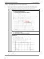
7.20.16
Technical Specifications
16QAM BER Performance (LDPC)
1E-1
16QAM Uncoded Theory
1E-2
LDPC Decoder
1E-3
1E-4
BER
Typical
Performance
Specification
3/4 Rate
1E-5
1E-6
1E-7
1E-8
1E-9
0
1
2
3
4
5
6
7
8
9
10
11
12
Eb/No in dB
Figure 7-16 – DMD20/20LBST 16QAM BER Performance (LDPC)
MN-DMD20-20LBST Revision 14
ER-DMD20LBS-EA14 Rev -
7–24
DMD20/20LBST Universal Satellite Modem
BER
1E-3
1E-4
1E-5
1E-6
1E-7
1E-8
1E-9
1E-10
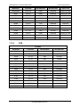
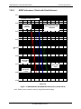
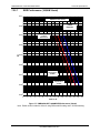
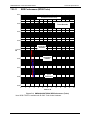
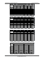
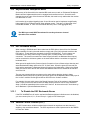
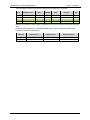
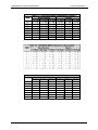
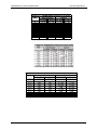
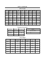
Table 7-1 - B/O/QPSK BER Performance (Viterbi)
Specification
Typical
1/2 Rate 3/4 Rate 7/8 Rate 1/2 Rate 3/4 Rate
4.2 dB
5.3 dB
6.2 dB
3.9 dB
4.9 dB
4.8 dB
6.1 dB
7.1 dB
4.5 dB
5.6 dB
5.5 dB
6.8 dB
7.9 dB
5.1 dB
6.3 dB
6.1 dB
7.6 dB
8.6 dB
5.7 dB
7 dB
6.7 dB
8.3 dB
9.3 dB
6.2 dB
7.7 dB
7.4 dB
8.9 dB
10.2 dB
6.8 dB
8.4 dB
8.2 dB
9.7 dB
11 dB
7.4 dB
9.1 dB
9 dB
10.3 dB 11.7 dB
8.1 dB
9.8 dB
Technical Specifications
7/8 Rate
5.8 dB
6.5 dB
7.2 dB
7.9 dB
8.6 dB
9.4 dB
10.1 dB
10.5 dB
Table 7-2 - B/O/QPSK BER Performance (Sequential)
BER
Specification
Typical
1/2 Rate 3/4 Rate 7/8 Rate 1/2 Rate 3/4 Rate 7/8 Rate
1E-3
4.8 dB
5.2 dB
6 dB
4.3 dB
4.7 dB
5.5 dB
1E-4
5.2 dB
5.7 dB
6.4 dB
4.7 dB
5.2 dB
5.9 dB
1E-5
5.6 dB
6.1 dB
6.9 dB
5.1 dB
5.6 dB
6.4 dB
1E-6
5.9 dB
6.5 dB
7.4 dB
5.4 dB
6.1 dB
6.9 dB
1E-7
6.3 dB
7 dB
7.9 dB
5.8 dB
6.5 dB
7.4 dB
1E-8
6.7 dB
7.4 dB
8.4 dB
6.2 dB
6.9 dB
7.9 dB
1E-9
7.1 dB
7.8 dB
8.9 dB
6.6 dB
7.4 dB
8.4 dB
1E-10
7.4 dB
8.3 dB
9.4 dB
6.9 dB
7.8 dB
8.9 dB
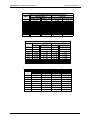
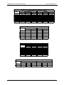
Table 7-3 - B/O/QPSK BER Performance (Viterbi - w/RS)
BER
Specification
Typical
1/2 Rate 3/4 Rate 7/8 Rate 1/2 Rate 3/4 Rate 7/8 Rate
1E-3
3.3 dB
5.1 dB
3 dB
4.3 dB
5.3 dB
1E-4
3.5 dB
5.3 dB
3.2 dB
4.5 dB
5.7 dB
1E-5
3.8 dB
5.4 dB
6.5 dB
3.4 dB
4.7 dB
6 dB
1E-6
4.1 dB
5.6 dB
6.7 dB
3.6 dB
4.9 dB
6.4 dB
1E-7
4.2 dB
5.8 dB
6.9 dB
3.8 dB
5.1 dB
6.7 dB
1E-8
4.4 dB
6 dB
7.2 dB
4 dB
5.3 dB
7.1 dB
1E-9
4.7 dB
6.1 dB
7.5 dB
4.2 dB
5.4 dB
7.4 dB
1E-10
5 dB
6.3 dB
7.8 dB
4.4 dB
5.6 dB
7.7 dB
Table 7-4 - B/O/QPSK BER Performance (Turbo)
Specification
Typical
Turbo 0.495 Turbo 0.793 Turbo 0.495 Turbo 0.793
1E-3
2.5 dB
3.3 dB
2.2 dB
3 dB
1E-4
2.7 dB
3.7 dB
2.3 dB
3.2 dB
1E-5
3 dB
4.1 dB
2.5 dB
3.4 dB
1E-6
3.2 dB
4.4 dB
2.6 dB
3.6 dB
1E-7
3.5 dB
4.8 dB
2.7 dB
3.8 dB
1E-8
3.7 dB
5.2 dB
2.9 dB
4 dB
1E-9
4 dB
5.6 dB
3 dB
4.2 dB
1E-10
4.2 dB
5.9 dB
3.2 dB
4.4 dB
BER
MN-DMD20-20LBST Revision 14
ER-DMD20LBS-EA14 Rev -
7–25
DMD20/20LBST Universal Satellite Modem
BER
1E-3
1E-4
1E-5
1E-6
1E-7
1E-8
1E-9
1E-10
Technical Specifications
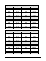
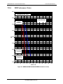
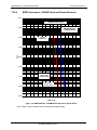
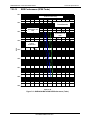
Table 7-5 - 8PSK BER Performance (Trellis)
Specification
Typical
2/3 Rate 2/3 Rate w/RS 2/3 Rate 2/3 Rate w/RS
6.3 dB
5.8 dB
4.8 dB
4.9 dB
7.3 dB
6.1 dB
5.6 dB
5.1 dB
8.2 dB
6.3 dB
6.4 dB
5.4 dB
9 dB
6.5 dB
7.2 dB
5.6 dB
9.8 dB
6.7 dB
8.1 dB
5.8 dB
10.4 dB
6.9 dB
8.9 dB
6.1 dB
11.1 dB
7.1 dB
9.7 dB
6.3 dB
11.9 dB
7.3 dB
10.5 dB
6.6 dB
Table 7-6 - 8PSK BER Performance (Turbo)
Specification
Typical
Turbo 0.495 Turbo 0.793 Turbo 0.495 Turbo 0.793
1E-3
7 dB
4.2 dB
5.4 dB
1E-4
7.3 dB
4.3 dB
5.6 dB
1E-5
7.7 dB
4.5 dB
5.9 dB
1E-6
8 dB
4.6 dB
6.2 dB
1E-7
8.4 dB
4.7 dB
6.4 dB
1E-8
8.7 dB
4.9 dB
6.7 dB
1E-9
9.1 dB
5 dB
7 dB
1E-10
9.5 dB
5.2 dB
7.3 dB
BER
Table 7-7 - 16QAM BER Performance (Viterbi)
BER
Specification
Typical
3/4 Rate 7/8 Rate 3/4 Rate 7/8 Rate
1E-3
8.9 dB
10.3 dB
8.1 dB
9.5 dB
1E-4
9.8 dB
11.1 dB
9 dB
10.3 dB
1E-5
10.7 dB 11.9 dB
9.9 dB
11.1 dB
1E-6
11.5 dB 12.7 dB 10.7 dB 11.9 dB
1E-7
12.4 dB 13.5 dB 11.6 dB 12.7 dB
1E-8
13.3 dB 14.3 dB 12.5 dB 13.5 dB
1E-9
14.2 dB 15.1 dB 13.4 dB 14.3 dB
1E-10
15 dB
15.9 dB 14.2 dB 15.1 dB
Table 7-8 - 16QAM BER Performance (Viterbi w/RS)
BER
Specification
Typical
3/4 Rate 7/8 Rate 3/4 Rate 7/8 Rate
1E-3
8.4 dB
9.8 dB
7.8 dB
9.3 dB
1E-4
8.6 dB
8.1 dB
8.1 dB
9.6 dB
1E-5
8.9 dB
8.3 dB
8.3 dB
9.9 dB
1E-6
9.1 dB
8.6 dB
8.6 dB
10.2 dB
1E-7
9.3 dB
8.8 dB
8.8 dB
10.4 dB
1E-8
9.5 dB
9.1 dB
9.1 dB
10.7 dB
1E-9
9.8 dB
9.3 dB
9.3 dB
11 dB
1E-10
10 dB
9.6 dB
9.6 dB
11.3 dB
MN-DMD20-20LBST Revision 14
ER-DMD20LBS-EA14 Rev -
7–26
DMD20/20LBST Universal Satellite Modem
BER
1E-3
1E-4
1E-5
1E-6
1E-7
1E-8
1E-9
1E-10
BER
1E-3
1E-4
1E-5
1E-6
1E-7
1E-8
Technical Specifications
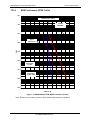
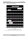
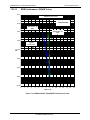
Table 7-9 - 16QAM BER Performance (Turbo)
Typical
Specification
Turbo 0.495 Turbo 0.793 Turbo 0.495 Turbo 0.793
5.6 dB
7 dB
6.1 dB
7.4 dB
6.6 dB
7.8 dB
7 dB
8.2 dB
7.5 dB
8.6 dB
8 dB
9 dB
8.5 dB
9.4 dB
9 dB
9.9 dB
Table 7-10 - (O)QPSK BER Performance (Turbo)
Specification
Typical
1/2 Rate 3/4 Rate 7/8 Rate 1/2 Rate 3/4 Rate
3.2 dB
4 dB
2.8 dB
3.4 dB
4.1 dB
3 dB
2.7 dB
3.6 dB
4.2 dB
2.4 dB
3.2 dB
2.9 dB
3.8 dB
4.3 dB
2.6 dB
3.4 dB
3.1 dB
4.1 dB
4.4 dB
2.8 dB
3.7 dB
3.3 dB
4.4 dB
4.5 dB
3 dB
4 dB
7/8 Rate
3.7 dB
3.8 dB
3.9 dB
4 dB
4.1 dB
4.2 dB
Table 7-11 - BPSK BER Performance (Turbo)
BER
Specification
Typical
5/16 Rate 21/44 Rate 5/16 Rate 21/44 Rate
1E-5
2.7 dB
2.4 dB
1E-6
2.7 dB
2.9 dB
2.5 dB
2.6 dB
1E-7
2.9 dB
3.1 dB
2.7 dB
2.8 dB
1E-8
3.1 dB
3.3 dB
2.9 dB
3 dB
Table 7-12 - 8PSK BER Performance (Turbo)
BER
Specification
Typical
3/4 Rate 7/8 Rate 3/4 Rate 7/8 Rate
1E-3
5.6 dB
6.7 dB
5.4 dB
6.3 dB
1E-4
5.8 dB
6.8 dB
5.6 dB
6.4 dB
1E-5
6 dB
6.9 dB
5.8 dB
6.5 dB
1E-6
6.2 dB
7 dB
6 dB
6.6 dB
1E-7
6.4 dB
7.1 dB
6.2 dB
6.7 dB
1E-8
6.8 dB
7.2 dB
6.6 dB
6.8 dB
MN-DMD20-20LBST Revision 14
ER-DMD20LBS-EA14 Rev -
7–27
DMD20/20LBST Universal Satellite Modem
Technical Specifications
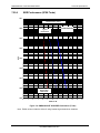
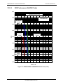
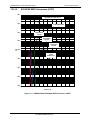
Table 7-13 - 16QAM BER Performance (Turbo)
BER
Specification
Typical
3/4 Rate 7/8 Rate 3/4 Rate 7/8 Rate
1E-3
6.3 dB
7.8 dB
6 dB
7.4 dB
1E-4
6.7 dB
7.9 dB
6.4 dB
7.5 dB
1E-5
7 dB
8 dB
6.7 dB
7.6 dB
1E-6
7.4 dB
8.1 dB
7.1 dB
7.7 dB
1E-7
7.8 dB
8.2 dB
7.5 dB
7.8 dB
1E-8
8.2 dB
8.3 dB
7.9 dB
7.9 dB
Table 7-13 - 16QAM BER Performance (Turbo)
BER
Specification
Typical
3/4 Rate 7/8 Rate 3/4 Rate 7/8 Rate
1E-3
6.3 dB
7.8 dB
6 dB
7.4 dB
1E-4
6.7 dB
7.9 dB
6.4 dB
7.5 dB
1E-5
7 dB
8 dB
6.7 dB
7.6 dB
1E-6
7.4 dB
8.1 dB
7.1 dB
7.7 dB
1E-7
7.8 dB
8.2 dB
7.5 dB
7.8 dB
1E-8
8.2 dB
8.3 dB
7.9 dB
7.9 dB
BER
1E-5
1E-9
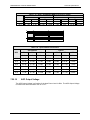
Table 7-15 - 8PSK / 8-QAM Rate BER Performance (LDPC)
8PSK
8-QAM
Specification
Typical
Specification
Typical
2/3 Rate 3/4 Rate 2/3 Rate 3/4 Rate 2/3 Rate 3/4 Rate 2/3 Rate 3/4 Rate
5.6 dB
5.2 dB
4.6 dB
5.6 dB
4.2 dB
5.2 dB
5.7 dB
6 dB
5.3 dB
5.6 dB
5 dB
6 dB
4.6 dB
5.6 dB
Table 7-16 - 16QAM BER Performance (LDPC)
Specification
Typical
BER
3/4 Rate
3/4 Rate
1E-5
6.8 dB
6.2 dB
1E-9
7.1 dB
6.8 dB
MN-DMD20-20LBST Revision 14
ER-DMD20LBS-EA14 Rev -
7–28
DMD20/20LBST Universal Satellite Modem
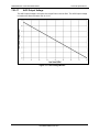
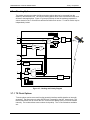
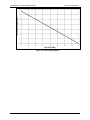
7.20.17
Technical Specifications
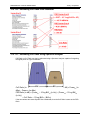
AGC Output Voltage
The AGC Output Voltage is a function of the Input Power Level in dBm. The AGC Output Voltage
is found on the Alarm connector Pin 14 of J15.
Figure 7-17 AGC Voltage Monitor
MN-DMD20-20LBST Revision 14
ER-DMD20LBS-EA14 Rev -
7–29
DMD20/20LBST Universal Satellite Modem
Technical Specifications
BLANK PAGE
MN-DMD20-20LBST Revision 14
ER-DMD20LBS-EA14 Rev -
7–30
Errata B for MN-DMD20-20LBST Rev 14
Comtech EF Data Documentation Update
Subject:
Errata Part Number:
PLM CO Number:
Comments:
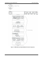
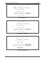
Chapter 3, Theory of Operation
ER-DMD20LBS-EB14
(Errata documents are not subject to revision.)
C-0028800
The new information will be included in the next released revision of the manual.
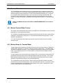
IMPORTANT
Set the modem to Loop Timing mode for these Loopback operations:
Tx/Rx Terrestrial Loopback
Tx/Rx Baseband Loopback
Rx Baseband Loopback
ER-DMD20LBS-EB14
Rev -
PLM C-0028800
Blank Page
ER-DMD20LBS-EB14
Rev -
PLM C-0028800
Comtech EF Data is an
AS9100 Rev B / ISO9001:2000 Registered Company
DMD20/DMD20LBST
Universal Satellite Modem
Installation and Operation Manual
Part Number MN-DMD20-20LBST
Revision 14
Copyright © 2013 Comtech EF Data. All rights reserved. Printed in the USA.
Comtech EF Data, 2114 West 7th Street, Tempe, Arizona 85281 USA, 480.333.2200, FAX: 480.333.2161
BLANK PAGE
Table of Contents
CHAPTER 1.
1.1
INTRODUCTION ..................................................................................1–1
Overview ................................................................................................................................ 1–1
1.2
Configurations ....................................................................................................................... 1–2
1.2.1
Features/Options Installed at Time of Order...................................................................... 1–2
1.2.2
Feature Upgrades ............................................................................................................. 1–2
1.2.3
Hardware Options ............................................................................................................ 1–2
1.2.4
Factory Installed Options .................................................................................................. 1–3
1.3
Function Accessibility ............................................................................................................ 1–3
CHAPTER 2.
INSTALLATION ...................................................................................2–1
2.1
Unpacking and Inspection ..................................................................................................... 2–1
2.2
Installation Requirements...................................................................................................... 2–2
2.3
Removal and Assembly .......................................................................................................... 2–3
2.4
Mounting Considerations ...................................................................................................... 2–3
2.5
Initial Configuration Check ................................................................................................... 2–4
2.6
Modulator Checkout .............................................................................................................. 2–6
2.6.1
Initial Power-Up ............................................................................................................... 2–6
2.6.2
Factory Terminal Setup .................................................................................................... 2–6
CHAPTER 3.
THEORY OF OPERATION ..................................................................3–1
3.1
Modem Hardware .................................................................................................................. 3–1
3.1.1
L-Band/IF Printed Circuit Card ........................................................................................ 3–2
3.1.2
Baseband Processing Printed Circuit Card ........................................................................ 3–3
3.1.3
Enhanced Interface Printed Circuit Card ........................................................................... 3–3
3.2
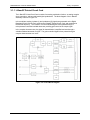
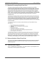
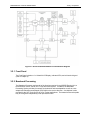
Functional Block Diagram ..................................................................................................... 3–3
3.2.1
Front Panel ....................................................................................................................... 3–4
3.2.2
Baseband Processing ........................................................................................................ 3–4
3.2.3
Tx Baseband Processing ................................................................................................... 3–5
3.2.4
Rx Baseband Processing ................................................................................................... 3–5
3.3
Monitor & Control (M&C) Subsystem ................................................................................. 3–5
3.3.1
Terminal Port ................................................................................................................... 3–6
3.3.2
Modem Remote Communications (RLLP) ........................................................................ 3–6
3.3.3
Ethernet M&C Port .......................................................................................................... 3–6
iii
Table of ContentsTable of Contents
DMD20/DMD20LBST Universal Satellite Modem
3.3.4
Revision 14
MN-DMD20-20LBST
Modem Monitor Status ..................................................................................................... 3–7
3.4
Async Port / ES-ES Communications.................................................................................... 3–7
3.5
Internal Clock ........................................................................................................................ 3–7
3.6
Loopback Features (Terrestrial & IF) .................................................................................. 3–8
3.7
Clocking Options ................................................................................................................. 3–11
3.7.1
TX Clock Options .......................................................................................................... 3–11
3.7.1.1 SCTE: Serial Clock Transmit External........................................................................ 3–12
3.7.1.2 SCT: Serial Clock Transmit ........................................................................................ 3–12
3.7.2
RX Buffer Clock Options ............................................................................................... 3–12
3.7.2.1 RX SAT Clock ........................................................................................................... 3–13
3.7.2.2 CTE: Serial Clock Transmit External .......................................................................... 3–13
3.7.2.3 SCT: Serial Clock Transmit ........................................................................................ 3–13
3.7.2.4 EXT CLK/EXT BNC: External Clock, J16 ................................................................. 3–13
3.7.2.5 EXT IDI: Insert Data In .............................................................................................. 3–13
3.7.3
EXT REF: External Reference, Top BNC Port, J10 ........................................................ 3–14
3.8
RS530/422/V.35 Interface (Standard) ................................................................................. 3–14
3.8.1
G.703 Interface (Optional) .............................................................................................. 3–14
3.8.2
HSSI Interface (Optional) ............................................................................................... 3–14
3.8.3
Ethernet Data Interface (Optional) .................................................................................. 3–14
3.9
Reed-Solomon Codec ........................................................................................................... 3–15
3.9.1
Reed-Solomon Operation ............................................................................................... 3–15
3.9.2
Reed-Solomon Code Rate............................................................................................... 3–15
3.9.3
Interleaving .................................................................................................................... 3–16
3.10
Asynchronous Overhead Operation (Framing/Multiplexer Capability) ............................ 3–17
3.11
Standard IBS Mode ............................................................................................................. 3–18
3.12
Asynchronous Multiplexer Mode ....................................................................................... 3–19
3.13 ESC Backward Alarms ........................................................................................................ 3–19
3.13.1 To Disable the ESC Backward Alarms ........................................................................... 3–19
3.14 Satellite Control Channel (SCC) ......................................................................................... 3–19
3.14.1 SCC Framing Structure .................................................................................................. 3–20
3.14.2 Aggregate Data Rate ...................................................................................................... 3–21
3.14.3 Overhead Rate Comparison ............................................................................................ 3–21
3.14.4 Actual Overhead Rate Calculation .................................................................................. 3–22
3.14.5 SCC Overhead Channel Setup ........................................................................................ 3–23
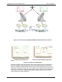
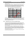
3.15 DoubleTalk Carrier-in-Carrier Option............................................................................... 3–25
3.15.1 What is DoubleTalk Carrier-in-Carrier? .......................................................................... 3–25
3.15.2 Application Requirements .............................................................................................. 3–25
3.15.3 Operational Recommendations ....................................................................................... 3–28
iv
Table of ContentsTable of Contents
DMD20/DMD20LBST Universal Satellite Modem
Revision 14
MN-DMD20-20LBST
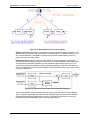
3.15.4 System Functionality and Operational Considerations..................................................... 3–29
3.15.5 DoubleTalk Carrier-in-Carrier Cancellation Process ....................................................... 3–31
3.15.6 Margin Requirements ..................................................................................................... 3–33
3.15.7 Carrier-in-Carrier Latency .............................................................................................. 3–33
3.15.8 Carrier-in-Carrier Link Design ....................................................................................... 3–33
3.15.8.1 Symmetric Data Rate Link.......................................................................................... 3–34
3.15.8.2 Asymmetric Data Rate Link ....................................................................................... 3–37
3.15.8.3 Power Limited Links .................................................................................................. 3–38
3.15.9 Carrier-in-Carrier Commissioning and Deployment ........................................................ 3–39
3.15.10
Validating Carrier-in-Carrier Performance .................................................................. 3–40
3.15.11
Operational References ............................................................................................... 3–41
3.15.12
Carrier-in-Carrier Link Budget Calculation ................................................................. 3–41
3.15.13
Estimating PSD Ratio ................................................................................................. 3–42
3.15.13.1 Estimating PSD Ratio from LST ................................................................................. 3–42
3.15.13.2 Estimating PSD Ratio from Satmaster ........................................................................ 3–43
3.15.13.3 Estimating PSD Ratio Using Spectrum Analyzer ........................................................ 3–43
3.15.14
DoubleTalk Carrier-in-Carrier Specifications .............................................................. 3–44
3.15.15
Carrier-in-Carrier Summary ........................................................................................ 3–44
3.15.16
Glossary ..................................................................................................................... 3–44
3.16
EDMAC Satellite Framing/Deframing Mode ..................................................................... 3–46
3.17
Locating the ID Code Operational Procedure .................................................................... 3–46
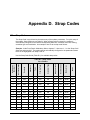
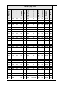
3.18
Strap Codes .......................................................................................................................... 3–46
CHAPTER 4.
4.1
USER INTERFACES............................................................................4–1
User Interfaces ....................................................................................................................... 4–1
4.2
Front Panel User Interface .................................................................................................... 4–1
4.2.1
LCD Front Panel Display ................................................................................................. 4–3
4.2.2
Cursor Control Arrow Keys .............................................................................................. 4–3
4.2.3
Numeric Keypad .............................................................................................................. 4–3
4.2.4
Front Panel LED Indicators .............................................................................................. 4–4
4.3
Parameter Setup .................................................................................................................... 4–4
4.4
Front Panel Control Screen Menus ....................................................................................... 4–5
4.4.1
Main Menus ..................................................................................................................... 4–5
4.4.2
Modulator Menu Options and Parameters ......................................................................... 4–6
4.4.3
Demodulator Menu Options and Parameters ................................................................... 4–15
4.4.4
Interface Menu Options and Parameters.......................................................................... 4–20
4.4.5
Monitor Menu Options and Parameters........................................................................... 4–25
4.4.6
Alarms Menu Options and Parameters ............................................................................ 4–28
4.4.7
System Menu Options and Parameters ............................................................................ 4–36
4.4.8
Test Menu Options and Parameters................................................................................. 4–45
4.5
Terminal Mode Control ....................................................................................................... 4–47
4.5.1
Modem Terminal Mode Control ..................................................................................... 4–47
v
Table of ContentsTable of Contents
DMD20/DMD20LBST Universal Satellite Modem
4.5.2
Revision 14
MN-DMD20-20LBST
Modem Setup for Terminal Mode ................................................................................... 4–47
4.6
Terminal Port User Interface .............................................................................................. 4–48
4.7
Connecting the Terminal ..................................................................................................... 4–48
4.8
Terminal Screens ................................................................................................................. 4–48
CHAPTER 5.
REAR PANEL INTERFACES ..............................................................5–1
5.1
DMD20/DMD20 LBST Connections ..................................................................................... 5–1
5.2
Compact Flash ....................................................................................................................... 5–4
5.3
Power Input Modules ............................................................................................................. 5–4
5.3.1
AC Power Input Module................................................................................................... 5–4
5.4
DMD20 Chassis Connections (Standard) .............................................................................. 5–4
5.4.1
EXT REF (J10) ................................................................................................................ 5–4
5.4.2
TX IF (J11) ...................................................................................................................... 5–4
5.4.3
TX L-Band IF (J12).......................................................................................................... 5–4
5.4.4
RX IF ............................................................................................................................... 5–5
5.4.5
RX L-Band IF .................................................................................................................. 5–5
5.4.6
ALARM (J15) .................................................................................................................. 5–5
5.4.7
EXT CLK (J16)................................................................................................................ 5–6
5.4.8
ASYNC (J17) ................................................................................................................... 5–6
5.4.9
J18 ................................................................................................................................... 5–6
5.4.10 EIA-530 (J19) .................................................................................................................. 5–7
5.4.11 REMOTE (J20) ................................................................................................................ 5–8
5.4.12 ETHERNET (J21) ............................................................................................................ 5–8
5.5
DMD20 LBST Chassis Connections (Standard) ................................................................... 5–9
5.5.1
EXT REF (J10) ................................................................................................................ 5–9
5.5.2
TX (J11)........................................................................................................................... 5–9
5.5.3
RX (J14) .......................................................................................................................... 5–9
5.5.4
ALARM (J15) .................................................................................................................. 5–9
5.5.5
EXT CLK (J16).............................................................................................................. 5–10
5.5.6
ASYNC (J17) ................................................................................................................. 5–10
5.5.7
(J18)............................................................................................................................... 5–10
5.5.8
EIA-530 (J19) ................................................................................................................ 5–11
5.5.9
REMOTE (J20) .............................................................................................................. 5–12
5.5.10 ETHERNET (J21) .......................................................................................................... 5–12
5.6
DMD20/DMD20 LBST Optional Data Interfaces ............................................................... 5–12
5.7
IDR/IBS Interface (Optional) .............................................................................................. 5–12
5.8
G.703 IDR/IBS Interface (Optional) ................................................................................... 5–13
5.8.1
ESC ALARM (J1) .......................................................................................................... 5–13
5.8.2
64K AUDIO (J2) ............................................................................................................ 5–14
vi
Table of ContentsTable of Contents
DMD20/DMD20LBST Universal Satellite Modem
5.8.3
5.8.4
5.8.5
5.8.6
5.8.7
5.8.8
5.8.9
5.9
Revision 14
MN-DMD20-20LBST
8K DATA (J3) ............................................................................................................... 5–15
G.703 BAL (J4).............................................................................................................. 5–16
SWITCH INTERFACE (J5) ........................................................................................... 5–17
SD (DDI) (J6) ................................................................................................................ 5–20
DDO (J7) ....................................................................................................................... 5–20
IDI (J8) .......................................................................................................................... 5–20
SD (IDO) (J9) ................................................................................................................ 5–20
Ethernet Data Interface (Optional) ..................................................................................... 5–20
5.10 High-Speed Serial Interface (HSSI) (Optional)................................................................... 5–21
5.10.1 HSSI (J6) ....................................................................................................................... 5–21
5.11 ASI/DVB/M2P Interface (Optional) .................................................................................... 5–21
5.11.1 ASI IN (J1) .................................................................................................................... 5–21
5.11.2 ASI OUT (J2)................................................................................................................. 5–21
5.11.3 DVB/M2P IN (J3) .......................................................................................................... 5–22
5.11.4 DVB/M2P OUT (J4) ...................................................................................................... 5–24
5.12
Ethernet Data Interface (Optional) ..................................................................................... 5–26
5.13 HSSI / G.703......................................................................................................................... 5–26
5.13.1 64K AUDIO (J2) ............................................................................................................ 5–27
5.13.2 8K DATA (J3) ............................................................................................................... 5–28
5.13.3 G.703 BAL (J4).............................................................................................................. 5–28
5.13.4 ESC ALARM (J5) .......................................................................................................... 5–29
5.13.5 SD (DDI) (J6) ................................................................................................................ 5–29
5.13.6 DDO (J7) ....................................................................................................................... 5–29
5.13.7 IDI (J8) .......................................................................................................................... 5–29
5.13.8 SD (IDO) (J9) ................................................................................................................ 5–30
5.14
HSSI / Ethernet (J1) ............................................................................................................. 5–30
5.15
Ethernet Data Interface ....................................................................................................... 5–31
5.16
GigE Interface ...................................................................................................................... 5–32
CHAPTER 6.
MAINTENANCE AND TROUBLESHOOTING .....................................6–1
6.1
Periodic Maintenance ............................................................................................................ 6–1
6.1.1
Clock Adjustment............................................................................................................. 6–1
6.2
Troubleshooting ..................................................................................................................... 6–1
6.2.1
Alarm Faults .................................................................................................................... 6–2
6.2.1.1 Major Tx Alarms .......................................................................................................... 6–2
6.2.1.2 Major Rx Alarms .......................................................................................................... 6–3
6.2.1.3 Minor Tx Alarms .......................................................................................................... 6–3
6.2.1.4 Minor Rx Alarms ......................................................................................................... 6–4
6.2.1.5 Drop and Insert Alarms ................................................................................................ 6–5
6.2.1.6 Common Major Alarms ................................................................................................ 6–5
vii
Table of ContentsTable of Contents
DMD20/DMD20LBST Universal Satellite Modem
Revision 14
MN-DMD20-20LBST
6.2.2
Alarm Masks .................................................................................................................... 6–6
6.2.2.1 Active Alarms .............................................................................................................. 6–6
6.2.2.1.1
Major Alarms .................................................................................................................. 6–6
6.2.2.1.2
Minor Alarms .................................................................................................................. 6–6
6.2.2.1.3
Common Equipment Faults............................................................................................. 6–6
6.2.2.2 Latched Alarms ............................................................................................................ 6–7
6.2.2.3 Backward Alarms ......................................................................................................... 6–7
6.3
IBS Fault Conditions and Actions ......................................................................................... 6–7
CHAPTER 7.
TECHNICAL SPECIFICATIONS ..........................................................7–1
7.1
Data Rates .............................................................................................................................. 7–1
7.2
Modulator .............................................................................................................................. 7–1
7.3
Demodulator .......................................................................................................................... 7–2
7.4
Plesiochronous Buffer ............................................................................................................ 7–3
7.5
Monitor and Control .............................................................................................................. 7–3
7.6
DMD20/DMD20 LBST Drop and Insert (Optional) ............................................................. 7–3
7.7
Terrestrial Interfaces ............................................................................................................. 7–3
7.8
IDR/ESC Interface (Optional) ............................................................................................... 7–3
7.9
IBS/Synchronous Interface (Standard) ................................................................................. 7–3
7.10
High-Speed Serial Interface (HSSI) ...................................................................................... 7–4
7.11
ASI.......................................................................................................................................... 7–4
7.12
DVB/M2P ............................................................................................................................... 7–4
7.13
Ethernet Data Interface (Optional) ....................................................................................... 7–4
7.14
Gigi Ethernet Data Interface (Optional) ............................................................................... 7–4
7.15
HSSI / G703............................................................................................................................ 7–4
7.16
HSSI /ETHERNET ................................................................................................................ 7–4
7.17
Environmental ....................................................................................................................... 7–5
7.18
Physical .................................................................................................................................. 7–5
7.19 DMD20/DMD20 LBST Data Rate Limits ............................................................................. 7–5
7.19.1 Non-DVB......................................................................................................................... 7–5
viii
Table of ContentsTable of Contents
DMD20/DMD20LBST Universal Satellite Modem
7.19.2
Revision 14
MN-DMD20-20LBST
DVB ................................................................................................................................ 7–7
7.20 BER Specifications ................................................................................................................. 7–9
7.20.1 BER Performance (Viterbi) .............................................................................................. 7–9
7.20.2 BER Performance (Sequential) ....................................................................................... 7–10
7.20.3 BER Performance (Viterbi with Reed-Solomon) ............................................................. 7–11
7.20.4 BER Performance ((O)QPSK Turbo) .............................................................................. 7–12
7.20.5 BER Performance (B/O/QPSK Turbo)............................................................................ 7–13
7.20.6 BER Performance (8PSK Turbo) .................................................................................... 7–14
7.20.7 BER Performance (8PSK Trellis) ................................................................................... 7–15
7.20.8 BER Performance (8PSK Turbo) .................................................................................... 7–16
7.20.9 BER Performance (16QAM Viterbi)............................................................................... 7–17
7.20.10
BER Performance (16QAM Viterbi with Reed-Solomon) ........................................... 7–18
7.20.11
BER Performance (16QAM Turbo) ............................................................................ 7–19
7.20.12
BER Performance (16QAM Turbo) ............................................................................ 7–20
7.20.13
1/2 Rate B/O/QPSK BER Performance (LDPC).......................................................... 7–21
7.20.14
2/3 Rate Q/8PSK/8QAM BER Performance (LDPC) .................................................. 7–22
7.20.15
3/4 Rate Q/8PSK, 8/16QAM BER Performance (LDPC) ............................................ 7–23
7.20.16
AGC Output Voltage .................................................................................................. 7–28
APPENDIX A.
PRODUCT OPTIONS.......................................................................... A–1
A.1
Hardware Options ................................................................................................................ A–1
A.2
G.703/IDR ESC Interface ..................................................................................................... A–1
A.3
Internal High Stability .......................................................................................................... A–1
A.4
DC Input Prime Power ......................................................................................................... A–1
A.5
ASI/RS-422 Parallel .............................................................................................................. A–1
A.6
ASI/LVDS Parallel ................................................................................................................ A–1
A.7
HSSI ...................................................................................................................................... A–1
A.8
Ethernet Data Interface ........................................................................................................ A–1
A.9
Gigi Ethernet Data Interface ................................................................................................ A–2
A.10
HSSI / G.703.......................................................................................................................... A–2
A.11
HSSI / ETHERNET .............................................................................................................. A–2
A.12
Turbo Product Code / Variable Reed-Solomon ................................................................... A–2
A.13
Combination Low-density Parity Check (LDPC) and TPC Codec ..................................... A–2
A.14
Customized Options .............................................................................................................. A–2
ix
Table of ContentsTable of Contents
DMD20/DMD20LBST Universal Satellite Modem
APPENDIX B.
Revision 14
MN-DMD20-20LBST
FRONT PANEL UPGRADE PROCEDURE ......................................... B–1
B.1
Introduction ...........................................................................................................................B–1
B.2
Required Equipment..............................................................................................................B–1
B.3
Upgrade Procedure ................................................................................................................B–1
B.4
Demonstration Procedure ......................................................................................................B–3
B.4.1
Running in Demonstration Mode ......................................................................................B–5
B.4.2
Canceling Demonstration Mode .......................................................................................B–6
APPENDIX C.
CARRIER CONTROL ......................................................................... C–1
C.1
States ..................................................................................................................................... C–1
C.2
Carrier Off ............................................................................................................................ C–1
C.3
Carrier On ............................................................................................................................ C–1
C.4
Carrier Auto.......................................................................................................................... C–1
C.5
Carrier VSat.......................................................................................................................... C–2
C.6
Carrier RTS .......................................................................................................................... C–2
APPENDIX D.
D.1
STRAP CODES .................................................................................. D–1
Strap Codes ........................................................................................................................... D–1
D.2
Sample Applications ............................................................................................................. D–5
D.2.1
Operational Case Examples ............................................................................................. D–6
APPENDIX E.
TCP/IP ETHERNET SETUP ................................................................ E–1
E.1
Introduction ...........................................................................................................................E–1
E.2
TCP/IP Network Configuration ............................................................................................E–1
E.3
Network Configuration Summary .........................................................................................E–3
E.4
Ethernet Test ..........................................................................................................................E–3
E.4.1
Connecting the Modem Ethernet Cable to a Network Link................................................ E–3
E.4.2
Connecting the Modem Ethernet Cable Directly to a Computer (without a Network) ....... E–3
E.4.3
Testing the Ethernet connection using the Ping Program (Optional) .................................. E–6
APPENDIX F.
F.1
WEB INTERFACE SETUP GUIDE ..................................................... F–1
Introduction ........................................................................................................................... F–1
x
Table of ContentsTable of Contents
DMD20/DMD20LBST Universal Satellite Modem
Revision 14
MN-DMD20-20LBST
F.2
Setup ....................................................................................................................................... F–1
F.2.1
TCP-IP Menus ................................................................................................................. F–1
F.2.2
IP Address........................................................................................................................ F–2
F.3
Web Interface Security .......................................................................................................... F–2
F.3.1
Default User Accounts ..................................................................................................... F–2
F.3.2
User Account Data ........................................................................................................... F–3
F.1
User Account Setup.............................................................................................................. F–3
F.1.1
Edit the User ID. .............................................................................................................. F–4
F.1.2
Edit the Access Group. ..................................................................................................... F–4
F.1.3
Edit the Authentication Password. .................................................................................... F–4
F.2
Reset a User Account ............................................................................................................. F–5
F.3
Confirmation .......................................................................................................................... F–5
F.4
Equipment Website ................................................................................................................ F–6
F.4.1
Log in to the Equipment Website...................................................................................... F–7
F.5
Web Page Appearance ........................................................................................................... F–8
F.6
Configure Web Browsers for the Radyne WEB Interface .................................................... F–9
F.6.1
Configure Internet Explorer 9 for the Radyne WEB Interface ........................................... F–9
F.6.2
Configure Firefox for the Radyne WEB Interface ............................................................. F–9
F.6.2.1 Change the encoding: ................................................................................................. F–10
F.6.2.2 Install the Internet Explorer Tab V2 add-on ................................................................ F–11
F.6.3
Configure Chrome for the Radyne WEB Browser ........................................................... F–12
F.6.3.1 Change the encoding .................................................................................................. F–13
F.6.3.2 Install the Internet Explorer Tab for Chrome ............................................................... F–14
F.6.4
Configure Safari for the Radyne WEB Browser .............................................................. F–15
F.6.4.1 Empty the browser cache ............................................................................................ F–15
F.6.4.2 Reset the Ethernet M&C port...................................................................................... F–16
F.6.4.3 Re-enter the Modem IP address .................................................................................. F–16
F.6.4.4 Change the encoding .................................................................................................. F–18
F.6.5
Configure Maxthon for the Radyne WEB Browser ......................................................... F–19
F.6.5.1 Change the browser mode ........................................................................................... F–20
F.6.5.2 Change the encoding .................................................................................................. F–21
APPENDIX G.
AUPC OPERATION ............................................................................ G–1
G.1 Automatic Uplink Power Control (AUPC Operation) ......................................................... G–1
G.1.1
Radyne AUPC ................................................................................................................. G–1
G.1.2
EF AUPC ........................................................................................................................ G–2
G.1.3
Near Side AUPC ............................................................................................................. G–2
APPENDIX H.
DROP AND INSERT (D&I) .................................................................. H–1
H.1 Drop and Insert (D&I) .......................................................................................................... H–1
H.1.1
Drop Only ....................................................................................................................... H–3
xi
Table of ContentsTable of Contents
DMD20/DMD20LBST Universal Satellite Modem
Revision 14
MN-DMD20-20LBST
H.1.2
Insert Only ...................................................................................................................... H–3
H.1.3
Mode Selection ............................................................................................................... H–4
H.1.3.1 PCM-30 ...................................................................................................................... H–4
H.1.3.2 PCM-30C .................................................................................................................... H–4
H.1.3.3 PCM-31 ...................................................................................................................... H–4
H.1.3.4 PCM-31C .................................................................................................................... H–4
H.1.3.5 T1-D4/T1-D4-S ........................................................................................................... H–5
H.1.3.6 T1-ESF/T1-ESF-S ....................................................................................................... H–5
H.1.4
Multidestinational Systems .............................................................................................. H–5
H.1.5
Drop and Insert Mapping ................................................................................................. H–6
H.2 Configuring the Modem for Drop and Insert ...................................................................... H–8
H.2.1
Data Rate ........................................................................................................................ H–8
H.2.2
Operational Network Specification .................................................................................. H–9
H.2.3
Terrestrial Framing - Drop Mode/Insert Mode ................................................................. H–9
H.2.3.1 Insert Terrestrial Frame Source .................................................................................... H–9
H.2.4
D&I Sample Configurations and D&I Clock Setup Options ........................................... H–10
H.3
D&I Maps and Map Editing ............................................................................................... H–13
APPENDIX I.
EFFICIENT DROP AND INSERT (D&I).................................................I–1
I.1
Introduction ............................................................................................................................I–1
I.2
Prerequisite .............................................................................................................................I–1
I.3
Efficient Drop & Insert Mode ................................................................................................I–2
I.3.1 Calculating the Required Satellite Bandwidth ........................................................................ I–3
I.3.2 Calculating the Basic Efficient D&I Rate .............................................................................. I–3
I.3.3 Calculating the Efficient D&I Rate with E1 Signaling ........................................................... I–3
I.3.4 Calculating the Efficient D&I Rate with Enhanced Asynchronous Overhead ......................... I–3
I.3.4.1 Summary and Examples: ............................................................................................... I–4
APPENDIX J.
ETHERNET DATA INTERFACE SETUP .............................................J–1
J.1
Configure the modem to use the Ethernet Data Interface (Optional) .................................. J–1
J.1.1 Ethernet Flow Control ...........................................................................................................J–1
J.1.1.1 Half-Duplex Flow Control .............................................................................................J–2
J.1.1.2 Full-Duplex Flow Control..............................................................................................J–2
J.1.2 Ethernet Daisy Chain ............................................................................................................J–2
J.1.3 Ethernet QOS Type ...............................................................................................................J–2
J.1.4 Ethernet QOS Queue .............................................................................................................J–2
J.1.5 Set up the Ethernet Bridge to operate like a FIFO ..................................................................J–3
J.1.6 Packet Statistics ....................................................................................................................J–4
xii
PREFACE
About this Manual
This manual describes the installation and operation of the DMD20/DMD20LBST Universal
Satellite Modem.
Conventions and References
Patents and Trademarks
See all of Comtech EF Data's Patents and Patents Pending at http://patents.comtechefdata.com.
Comtech EF Data acknowledges that all trademarks are the property of the trademark owners.
•
®
DoubleTalk is licensed from "Raytheon Applied Signal Technology".
•
®
DoubleTalk is a registered trademark of "Raytheon Applied Signal Technology".
•
®
Carrier-in-Carrier is a registered trademark of Comtech EF Data.
Related Documents
The following documents are referenced in this manual:
• Department of Defense (DOD) MIL-STD-188-114A, Electrical Characteristics of Digital
Interface Circuits
• Department of Defense (DOD) MIL-STD-188-165A, Interoperability and Performance
Standards for SHF Satellite Communications PSK Modems (FDMA Operation) (dated
November 2005)
• INTELSAT Earth Station Standards IESS-308, -309, -310, and -315
• EUTELSAT SMS
Military Standards
References to “MIL-STD-188” apply to the 114A series (i.e., MIL-STD-188-114A), which provides
electrical and functional characteristics of the unbalanced and balanced voltage digital interface
circuits applicable to both long haul and tactical communications. Specifically, these references
apply to the MIL-STD-188-114A electrical characteristics for a balanced voltage digital interface
circuit, Type 1 generator, for the full range of data rates. For more information, refer to the
Department of Defense (DOD) MIL-STD-188-114A, Electrical Characteristics of Digital Interface
Circuits.
i
DMD20/DMD20LBST Universal Satellite ModemPreface
Preface
Revision 14
MN-DMD20-20LBST
Cautions and Warnings
IMPORTANT
CAUTION
IMPORTANT or NOTE indicates a statement associated with the task
being performed or information critical for proper equipment function.
CAUTION indicates a hazardous situation that, if not avoided, may result in
minor or moderate injury. CAUTION may also be used to indicate other
unsafe practices or risks of property damage.
WARNING indicates a potentially hazardous situation that, if not avoided,
could result in death or serious injury.
WARNING
Safety Compliance
EN 60950
Applicable testing is routinely performed as a condition of manufacturing on all units to ensure
compliance with safety requirements of EN60950.This equipment meets the Safety of Information
Technology Equipment specification as defined in EN60950.
Low Voltage Directive (LVD)
The following information is applicable for the European Low Voltage Directive (EN60950):
<HAR>
!
Type of power cord required for use in the European Community.
CAUTION: Double-pole/Neutral Fusing
ACHTUNG: Zweipolige bzw. Neutralleiter-Sicherung
International Symbols:
Symbol
Definition
Symbol
~
Alternating Current
Protective Earth /
Safety Ground
Fuse
Chassis Ground
ii
Definition
DMD20/DMD20LBST Universal Satellite ModemPreface
Preface
Revision 14
MN-DMD20-20LBST
Warranty Policy
Comtech EF Data products are warranted against defects in material and workmanship for a period of two years from the
date of shipment. During the warranty period, Comtech EF Data will, at its option, repair or replace products that prove to
be defective. Repairs are warranted for the remainder of the original two year warranty, or a 90 day extended warranty,
whichever is longer.
For equipment under warranty, the owner is responsible for freight to Comtech EF Data and all related customs, taxes, tariffs,
insurance, etc. Comtech EF Data is responsible for the freight charges only for return of the equipment from the factory to the
owner. Comtech EF Data will return the equipment by the same method (i.e., Air, Express, Surface) as the equipment was
sent to Comtech EF Data.
All equipment returned for warranty repair must have a valid RMA number issued prior to return and be marked clearly on
the return packaging. Comtech EF Data strongly recommends all equipment be returned in its original packaging.
Comtech EF Data Corporation’s obligations under this warranty are limited to repair or replacement of failed parts, and the
return shipment to the buyer of the repaired or replaced parts.
Limitations of Warranty
The warranty does not apply to any part of a product that has been installed, altered, repaired, or misused in any way that,
in the opinion of Comtech EF Data Corporation, would affect the reliability or detracts from the performance of any part of
the product, or is damaged as the result of use in a way or with equipment that had not been previously approved by
Comtech EF Data Corporation.
The warranty does not apply to any product or parts thereof where the serial number or the serial number of any of its parts has
been altered, defaced, or removed.
The warranty does not cover damage or loss incurred in transportation of the product.
The warranty does not cover replacement or repair necessitated by loss or damage from any cause beyond the control of
Comtech EF Data Corporation, such as lightning or other natural and weather related events or wartime environments.
The warranty does not cover any labor involved in the removal and or reinstallation of warranted equipment or parts on
site, or any labor required to diagnose the necessity for repair or replacement.
The warranty excludes any responsibility by Comtech EF Data Corporation for incidental or consequential damages arising from
the use of the equipment or products, or for any inability to use them either separate from or in combination with any other
equipment or products.
A fixed charge established for each product will be imposed for all equipment returned for warranty repair where Comtech
EF Data Corporation cannot identify the cause of the reported failure.
Exclusive Remedies
Comtech EF Data Corporation’s warranty, as stated is in lieu of all other warranties, expressed, implied, or statutory,
including those of merchantability and fitness for a particular purpose. The buyer shall pass on to any purchaser, lessee,
or other user of Comtech EF Data Corporation’s products, the aforementioned warranty, and shall indemnify and hold
harmless Comtech EF Data Corporation from any claims or liability of such purchaser, lessee, or user based upon
allegations that the buyer, its agents, or employees have made additional warranties or representations as to product
preference or use.
The remedies provided herein are the buyer’s sole and exclusive remedies. Comtech EF Data shall not be liable for any
direct, indirect, special, incidental, or consequential damages, whether based on contract, tort, or any other legal theory.
iii
DMD20/DMD20LBST Universal Satellite ModemPreface
Preface
Revision 14
MN-DMD20-20LBST
Customer Support
Support Business Hours - Monday through Friday - 8:00 a.m. to 5:00 p.m. (MST)
Comtech EF Data & Radyne
•
•
•
•
•
•
•
•
•
•
•
•
•
Satellite Modems
Modem Accessories
Amplifiers
Converters
Transceivers
Terminals
IP-Enabled Satellite Modems
IP-Based Modem Accessories
Encapsulators, Receivers, Filtering &
Encryption
turboIP® Performance Enhancement
Proxies (PEP)
SkyWire™ MDX420 Satellite Network
Gateway
Vipersat Network Products
IP-Enabled Satellite Modems used in
conjunction with VMS
Tel: +1.480.333.4357
Fax: +1.480.333.2500
Email: [email protected]
Tel: +1.480.333.2433
Fax: +1.480.333.2161
Email: [email protected]
Tel: +1.510.252.1462 - select option #2
Fax: +1.510.252.1695
Email: [email protected]
After Hours and Weekends:
Comtech
Tel: +1.480.333.4357
Radyne
Tel: +1.602.980.5220
iv
Chapter 1. INTRODUCTION
This chapter provides an overview of the DMD20/DMD20 LBST Universal Satellite Modem. The
DMD20 will be referred to in this manual as “the standard unit” and the DMD20 LBST will be
referred to as the LBST. When describing the DMD20/DMD20 LBST, it may be referred to as
“the DMD20”, “the modem”, or “the unit”.
1.1
Overview
The Radyne DMD20/DMD20 LBST Universal Satellite Modem (Figure 1-1 & Figure 1-2) offers the
best features of a sophisticated programmable IBS/IDR and Closed Network Modem, at an
affordable price
Figure 1-1 DMD20 Universal Satellite Modem Front Panel
Figure 1-2 DMD20 LBST Universal Satellite Modem Front Panel
This versatile equipment package combines unsurpassed performance with numerous userfriendly Front Panel Programmable Functions. The unit provides selectable functions for different
services: Intelsat IDR and IBS, DVB, Low-density Parity Check Coding (LDPC) and Closed
Networks are supported. All of the configuration and Monitor and Control (M&C) Functions are
available at the Front Panel. Operating parameters, such as variable data rates, FEC Code Rate,
modulation type, IF Frequencies, IBS/IDR Framing and interface type can be readily set and
changed at the Front Panel by earth station operations personnel.
The modem operates at all standard IBS and IDR Data Rates up to 8.448 Mbps. Selection of any
data rate is provided over the range of 2.4 Kbps to 20 Mbps in 1 bps steps.
For applications requiring system redundancy, the Modem may be used with the Radyne RCS11
1:1 Redundancy Switch or the RCS20 M:N (N < 9) Redundancy Switch. An Internal Engineering
Service Channel Unit is available to provide voice, data, and alarms for Intelsat IDR applications.
A full range of Industry Standard Interfaces are available. Interface types are selectable from
V.35, RS-232, RS-422/-530, ITU G.703, HSSI, ASI, DVB/M2P and Ethernet Bridge.
MN-DMD20-20LBST Revision 14
1–1
DMD20/20LBST Universal Satellite Modem
Introduction
The DMD20 LBST (Figure 1-2) offers additional features that are not included in the standard
DMD20 Modem. The features included in DMD20 LBST serves as an interface between the
indoor unit (DMD20 LBST) and the outdoor units (consisting of the BUC and LNB). The output
frequency of the LBST is 950 to 2050 MHz. It does not offer a 70 MHz output that is included in
the standard unit. The LBST can supply voltage and 10 MHz reference to the BUC and LNB via
the IFL Cable. The output from the Tx Port consists of the L-Band output frequency, high-stability
10 MHz reference, FSK communications and either 24 or 48 Volts to the BUC. The Rx Port
consists of the L-Band input frequency, high-stability 10 MHz reference and 13, 15, 18, and 21
volts.
The LBST has the capability to enable and disable the BUC/LNB voltages and 10 MHz reference
via the front panel. In addition, monitoring features provide verification of system status. The
LBST monitors both the current and the voltage at the output of the Tx and Rx Ports, thus
allowing the user to monitor the status of both the indoor units and outdoor units.
1.2
Configurations
The DMD20/DMD20 LBST can be configured in the following different ways:
•
•
•
•
features and options that are installed when the unit is ordered
feature upgrades
hardware options that are installed to a unit that is sent to a Radyne facility
hardware options that the user can install at their own location
1.2.1 Features/Options Installed at Time of Order
Features installed at the time of ordering are the options pre-installed/initialized in the factory prior
to shipment. These can be reviewed from the front panel system menu. Refer to Section 4, User
Interfaces for information on how to view these features.
Factory installed options are chassis and board configurations that are introduced during
manufacturing.
1.2.2 Feature Upgrades
Feature Upgrades are soft upgrades that can be easily be enabled on the modem. Enabling new
features are done remotely or through the front panel of the modem. Features may be purchased
at any time by contacting a Radyne Corp. salesperson. Refer to Section 4 and Appendix B, for
information on how upgrade features are enabled.
1.2.3 Hardware Options
Hardware options (refer to Appendix A) are purchased parts that can be installed into the unit at
the customer’s site. A screwdriver is normally the only tool required. Please contact the Radyne
Corp. Customer Service Department for information pertaining to availability and to shipping
costs.
MN-DMD20-20LBST Revision 14
1–2
DMD20/20LBST Universal Satellite Modem
Introduction
Only authorized service personnel should handle and install optional
hardware options.
IMPORTANT
1.2.4 Factory Installed Options
Units may also be sent to the factory for hardware option installation. Please contact the
Customer Service Department for information not limited to availability and to shipping costs.
1.3
Function Accessibility
All functions can be accessed through the front panel, terminal or personal computer via a serial
link or via the Ethernet port offering a complete remote monitoring and control capability.
MN-DMD20-20LBST Revision 14
1–3
DMD20/20LBST Universal Satellite Modem
Introduction
BLANK PAGE
MN-DMD20-20LBST Revision 14
1–4
Chapter 2. INSTALLATION
2.1
Unpacking and Inspection
Inspect shipping containers for damage. If shipping containers are damaged, keep them until the
contents of the shipment have been carefully inspected and checked for normal operation.
The Universal Satellite Modem and its Installation and Operation Manual are packaged and shipped
in a pre-formed, reusable cardboard carton containing foam spacing for maximum shipping
protection.
Do not use any cutting tool that will extend more than 1/2 inch into the
container. This can cause damage to the modem.
CAUTION
Unpack and inspect the modem as follows:
Step
Procedure
1
Cut the tape at the top of the carton indicated by OPEN THIS END.
2
Remove the cardboard/foam space covering the modem.
3
Remove the modem, power cord, and user’s manual from the carton.
4
Save the packing material for storage or reshipment purposes.
5
Inspect the equipment for any possible damage incurred during shipment.
Note: If damage is evident, contact the carrier and Comtech EF Data immediately
and submit a damage report.
6
Check the contents against the packing list to verify completeness of the
shipment.
7
Refer to the sections that follow for further installation instructions.
The Universal Satellite Modem was carefully packaged to avoid damage and should arrive
complete with the following items for proper installation:
1.
2.
3.
DMD20/DMD0=20LBST Universal Satellite Modem
Power Cord, six foot with applicable AC Connector
Installation and Operation Manual
IMPORTANT Should the AC power cable connector be of the wrong type for the installation, either
the cable or the power connector end should be replaced.
MN-DMD20-20LBST Revision 14
2–1
DMD20/20LBST Universal Satellite Modem
2.2
Installation
Installation Requirements
The modem is shipped fully assembled. It does not require removal of the covers for any
purpose in installation. The power supply itself is designed for universal application using from
100 to 240 VAC, 50 to 60 Hz, 1.0A.
WARNING
WARNING
CAUTION
There are no user-serviceable parts or configuration settings located inside
the Chassis. There is a potential shock hazard internally at the power supply
module. DO NOT open the Chassis under any circumstances.
The unit contains a Lithium Battery. DANGER OF EXPLOSION exists if the
battery is incorrectly replaced. Replace only with the same or equivalent type
recommended by the manufacturer. Dispose of used batteries in accordance
with local and national regulations.
Before initially applying power to the unit, it is a good idea to disconnect the
transmit output from the operating ground station equipment. This is
especially true if the current configuration settings are unknown, where
incorrect settings could disrupt existing communications traffic.
MN-DMD20-20LBST Revision 14
2–2
DMD20/20LBST Universal Satellite Modem
2.3
Installation
Removal and Assembly
The Modem is shipped fully assembled. It does not require removal of the covers for any
purpose in installation.
Always ensure that power is removed from the before removing or installing
any optional modules. Failure to do so may cause damage to the equipment.
CAUTION
Carefully unpack the unit and ensure that all of the above items are in the carton. If the available
AC mains power at the installation site requires a different cord set from the one included in the
package, then a suitable and approved cord set (for the country where the equipment is to be
installed) will be required before proceeding with the installation.
Should the Power Cable/AC Connector be of the wrong type for the installation, either the cable
or the power connector end should be replaced. The power supply itself is designed for universal
AC application. See specifications for appropriate voltages and currents.
2.4
Mounting Considerations
The can be installed within any standard 19 inch equipment cabinet or rack. The unit is a one
rack unit (RU) mounting space (1.75 inches) vertically and 19 inches of depth and requires a
minimum rack depth of 22 inches for cabling. The rear panel of the DMD50 is designed to have
power enter from the left and IF Cabling enter from the right when viewed from the rear of the
unit. Data and control cabling can enter from either side based on data interface option. The
unit can be placed on a table or suitable surface if required
When mounted in an equipment rack, adequate ventilation must be provided. The ambient
temperature in the rack should be between 10° and 35° C, and held constant for best equipment
operation. The air available to the rack should be clean and relatively dry. The DMD50 units may
be stacked one on top of the other up to a maximum of 10 consecutive units before providing one
RU of space for airflow. Demodulator units should not be placed immediately above a high heat
or EMF generator to ensure the output signal integrity and proper receive operation.
Do not mount the in an unprotected outdoor location where there is direct contact with rain, snow,
wind or sun. The is designed for indoor applications only.
Shielded cables with the shield terminated to the conductive backshells are required in order to
meet EMC directives. Cables with insulation flammability ratings of 94 VO or better are required
in order to meet low voltage directives.
The unit CANNOT have rack slides mounted to the side of the chassis.
Cooling fans are mounted on the right-hand side of the unit.
IMPORTANT
If the unit is to be mounted in a rack, ensure that there is adequate clearance
for ventilation, particularly at the sides. In rack systems where there is high
heat dissipation, forced air cooling must be provided by top or bottom
mounted fans or blowers. Under no circumstance should the highest internal
rack temperature be allowed to exceed 50°C (122°F).
PROPER GROUNDING PROTECTION REQUIRED: The installation
instructions require that the integrity of the protective earth must be
ensured and that the equipment shall be connected to the protective earth
MN-DMD20-20LBST Revision 14
2–3
DMD20/20LBST Universal Satellite Modem
Installation
connection at all times. Therefore, it is imperative during installation,
configuration, and operation that the user ensures that the unit has been
properly grounded using the ground stud provided on the rear panel of
the unit.
2.5
•
In Finland: "Laite on liitettävä suojamaadoituskoskettimilla
varustettuun pistorasiaan."
•
In Norway: “Apparatet må tilkoples jordet stikkontakt.”
•
In Sweden: “Apparaten skall anslutas till jordat uttag.”
Initial Configuration Check
The is shipped from the factory with preset factory defaults. Upon initial power-up, a user check
should be performed to verify the shipped modem configuration. Refer to Section 4, User
Interfaces to locate and verify that the following configuration settings are correct:
Transmit (Tx) and Receive (Rx) Interface types are dependent upon the
customer’s order.
IMPORTANT
IMPORTANT
Implementing Strap Code 26 can set the following modem configuration. Refer
to Table D-1 for an explanation and tabular listing of available Strap Codes.
The Frequency and Modulator Output Power are set independently of the strap
code.
MN-DMD20-20LBST Revision 14
2–4
DMD20/20LBST Universal Satellite Modem
Installation
Standard Factory Configuration Settings
Modulator:
Data Rate:
Mode:
Satellite Framing:
Scrambler:
Drop and Insert:
Inner FEC:
Outer FEC:
Modulation:
2.048 Mbps
Closed Network
None
V.35 (IESS)
Disabled
1/2 Rate Viterbi
Disabled
QPSK
Frequency:
Modulator Output Power:
70.000000 MHz
-20 dBm
Demodulator:
Data Rate:
Mode:
Satellite Framing:
Scrambler:
Drop and Insert:
Inner FEC:
Outer FEC:
Modulation:
2.048 Mbps
Closed Network
None
V.35 (IESS)
Disabled
1/2 Rate Viterbi
Disabled
QPSK
Frequency:
70.000000 MHz
To lock up the modem, enter ‘IF Loopback Enable’ under the Test Menu, or connect a Loopback
Cable from J11 to J13 on the rear panel of the modem.
MN-DMD20-20LBST Revision 14
2–5
DMD20/20LBST Universal Satellite Modem
2.6
Installation
Modulator Checkout
The following descriptions assume that the unit is installed in a suitable location with prime AC
power and supporting equipment available.
2.6.1 Initial Power-Up
CAUTION
Before initial power up of the unit, it is a good idea to disconnect the transmit
output from the operating ground station equipment. This is especially true if
the current Modulator Configuration Settings are unknown, where incorrect
settings could disrupt the existing communications traffic. New units from
the factory are normally shipped in a default configuration which includes
setting the transmit carrier off.
Turn on the unit by placing the Rear Panel Switch (located above the power entry connector) to
the On Position. Upon initial and subsequent power-ups, the Microprocessor will test itself and
several of its components before beginning its Main Monitor/Control Program. These power-up
diagnostics show no results if successful. If a failure is detected, the Fault LED will illuminate.
The initial field checkout of the modem can be accomplished from the Front Panel or in the
Terminal Mode. The Terminal Mode has the advantage of providing full screen access to all of
the modem’s parameters, but requires a separate terminal or computer running a Terminal
Program. The Terminal Mode is enabled from the front panel in the System M&C Submenus.
2.6.2 Factory Terminal Setup
The factory terminal setup is as follows:
Emulation Type:
Baud Rate:
Data Bits:
Parity:
Stop Bits:
MN-DMD20-20LBST Revision 14
VT-100 (can be changed)
19.2 K (can be changed via Front Panel)
8
No Parity (Fixed)
1 Stop Bit
2–6
Chapter 3. THEORY OF
OPERATION
3.1
Modem Hardware
The modem is based on a two printed circuit card (minimum configuration) design with additional
optioned printed circuit cards available for additional features. The minimum configuration
consists of an L-Band/IF Assembly and a Digital Baseband Assembly. The optional printed circuit
cards include a Turbo Codec printed circuit card and one of several types of Interface printed
circuit card (refer to Appendix A). A block diagram of the Modem is shown in Figure 3-1.
Figure 3-1 Block Diagram
MN-DMD20-20LBST Revision 14
3–1
DMD20/20LBST Universal Satellite Modem
Theory of Operation
3.1.1 L-Band/IF Printed Circuit Card
The L-Band/IF Printed Circuit Card consists of an analog modulation function, an analog complex
down conversion, and two wide-band digital synthesizers. The block diagram of the L-Band/IF
Assembly is shown in Figure 3-2.
In the modulator, analog in-phase (I) and quadrature (Q) signals are generated on the Digital
Baseband Printed Circuit Card, routed to the L-Band/IF Printed Circuit Card, and modulated at
the desired frequency. The L-Band or 70/140 modulated signal is then passed through a
microprocessor controlled variable attenuator providing gain control of the output signal.
In the complex downconverter, the signal for demodulation is amplified and sent through a
variable wideband attenuator for AGC. The gain-controlled signal is then passed through a
complex downconverter to a low IF.
Figure 3-2 IF Card Block Diagram
MN-DMD20-20LBST Revision 14
3–2
DMD20/20LBST Universal Satellite Modem
Theory of Operation
3.1.2 Baseband Processing Printed Circuit Card
The advent of million-plus gate count FPGAs, advanced logic synthesis tools, and DSPs
providing hundreds of MIPs enabled the design of a software configurable modem. Large, fast
FPGAs now provide designers with what is essentially an on the fly programmable ASIC. High
speed, complex digital logic functions that previously could only be implemented in dedicated
integrated circuits are now downloaded from a micro-controller through a serial or peripheral
interface. When a new digital logic function is needed, a new configuration file is loaded into the
FPGA. There is no limit to the number of digital logic configurations available to the FPGA, aside
from the amount of Flash memory available to the system microprocessor for storage of
configuration files.
The Baseband Processing Printed Circuit Card provides a flexible architecture that allows many
different modes of terrestrial and satellite framing, various FEC options, digital voice processing,
and several different modulation/demodulation formats. Also included on the Baseband Printed
Circuit Card are three synchronous interfaces, an EIA-530 Interface supporting RS-422, V.35,
and RS-232. All three interfaces are provided on the same DB-25 Connector, and are selectable
from the front panel.
The Baseband Printed Circuit Card also contains the Monitor and Control (M&C) Circuitry
responsible for:
•
•
•
•
•
•
•
Programmable part setup and initialization
Continuous control and adjustment of some functions
Calibration
Monitoring fault status
Calculating and displaying measurements
User monitor and control interface including front panel and remote
Units configuration and feature set
The M&C System is based on a powerful microprocessor with a large amount of Flash memory.
Several bus architectures are used to interconnect the M&C to all components of the modem.
Communication to the outside world is done via connections to the remote port, terminal port,
Ethernet port, and alarm ports. The M&C runs off of software programmed into its Flash memory.
The memory can be reprogrammed via the Ethernet port to facilitate changes in software.
3.1.3 Enhanced Interface Printed Circuit Card
The normal terrestrial data for the Baseband Processing Card can be re-routed to the enhanced
interface card. The enhanced interface card adds a variety of connections to the modem for
additional applications
3.2
Functional Block Diagram
Figure 3-3 represents the Functional Blocks. The modem is shown in a typical application with
customer data, Tx/Rx RF equipment and an antenna.
MN-DMD20-20LBST Revision 14
3–3
DMD20/20LBST Universal Satellite Modem
Theory of Operation
Figure 3-3 Universal Satellite Modem Functional Block Diagram
3.2.1 Front Panel
The Front Panel includes a 2 x 16 backlit LCD Display, Indicator LEDs, and a Numeric Keypad
(refer to Chapter 4).
3.2.2 Baseband Processing
The Baseband Processor performs all of the functions required for an IBS/IDR Framing Unit, a
Reed-Solomon Codec, and an E1/T1 Drop and Insert System. In addition, the Baseband
Processing Section provides for transmit clock selection and rate adaptation as well as a rate
adapter and Plesiochronous/Doppler (PD) Buffer in the receive direction. A multiplexer is also
provided for the SCT Clock Source for Loop Timing Applications. The transmit and receive paths
may be configured independently under processor control.
MN-DMD20-20LBST Revision 14
3–4
DMD20/20LBST Universal Satellite Modem
Theory of Operation
3.2.3 Tx Baseband Processing
The Tx Data and Clock enters the Baseband Processor, passes through a Rate Adapting FIFO
and enters the Framer/Drop Processor. In IDR, IBS, and D&I Modes, the framer adds the
appropriate framing and ESC as defined in IESS-308 and 309. In D&I Mode, the framer acquires
the terrestrial framing structure, E1 or T1, and synchronizes the Drop Processor. The Drop
Processor extracts the desired time slots from the terrestrial data stream and feeds these
channels back to the framer. The framer then places the ‘dropped’ terrestrial time slots into the
desired satellite channel slots. The data is then sent to the Reed-Solomon Encoder.
When enabled, the Reed-Solomon Encoder, encodes the data into Reed-Solomon Blocks. The
blocks are then interleaved and synchronized to the frame pattern as defined by the selected
specification (IESS-308, IESS-309, DVB, etc.). After Reed-Solomon Encoding, the composite
data and clock are applied to the BB Loopback Circuit.
3.2.4 Rx Baseband Processing
The Receive Processor performs the inverse function of the Tx Processor. Data received from
the satellite passes through the BB Loopback Circuit to the Reed-Solomon Decoder to the
Deframer. The Deframer acquires the IBS/IDR/DVB frame, synchronizes the Reed-Solomon
Decoder and extracts the received data and overhead from the frame structure, placing the data
into the PD Buffer, sending the overhead data to the UIM. The data is extracted from the buffer
and is sent to the UIM. Backward Alarm indications are sent to the M&C Subsystem. In Drop
and Insert Mode, the Insert Processor synchronizes to the incoming terrestrial T1/E1 Data
Stream, extracts satellite channels from the PD Buffer, and then inserts them into the desired
terrestrial time slots in the T1/E1 Data Stream.
3.3
Monitor & Control (M&C) Subsystem
The modems M&C system is connected to most of the circuitry on any board contained in the
modem. These connections provide status on the working condition of the circuitry as well as
providing the data required for the various measurements the modem provides. The M&C
processes this information and generates status indications as well as alarms when necessary.
Detailed status information is available via the modems various user interfaces including the
remote and terminal ports. An external summary fault is available on the RS422 Data interface
The M&C contains a high-performance microprocessor and is responsible for overall command
and control of modem functions. The M&C is constantly monitoring all subsystems of the modem
by performing a periodic poll routine and configures the modem by responding to commands
input to the system. During each poll cycle, the status of each of the subsystems is collected and
reported to each of the external ports. Performance statistics such as Eb/No, buffer fill %, etc.
are compiled. If faults are detected, the M&C will take appropriate actions to minimize the effect
of such faults on the system (refer to the Fault Matrices in Chapter 6).
The modem supports the following M&C protocols:
Terminal Interface (Section 3.3.1)
Remote Port Interface (Section 3.3.2)
Ethernet M&C, Web Browser & SNMP (Section 3.3.3)
Modem Status, Alarms & Contact Closures (Section 3.3.4)
MN-DMD20-20LBST Revision 14
3–5
DMD20/20LBST Universal Satellite Modem
Theory of Operation
3.3.1 Terminal Port
This port supports an asynchronous control protocol as described in Chapter 4. It is configured to
support RS-232 signal levels. This port is intended for use in computer-based remote M&C. All
functions of the modem may be monitored and controlled from this port via a common terminal
connected to the Terminal Port. This function is front panel selectable.
The Terminal Mode Control allows the use of an external terminal or computer to monitor and
control the modem from a full screen interactive presentation operated by the modem itself. No
external software is required other than VT-100 Terminal Emulation Software (e.g. “Procomm”
for a computer when used as a terminal. The Control Port is normally used as an RS–232
Connection to the terminal device. The RS-232 operating parameters can be set using the
modem Front Panel and stored in Non-volatile memory for future use.
Refer to the Remote Protocol Manual (MN-DMDREMOTEOP) for the Terminal,
Remote and SNMP screens and protocols.
IMPORTANT
3.3.2 Modem Remote Communications (RLLP)
The Remote Port located on J20 allows for control and monitoring of parameters and functions
via an RS-232 Serial Interface, or RS-485 for RLLP Protocol. ‘Equipment Remote Mode’ setup
can be entered from the front panel or the Web Browser interface under the “System” menu. This
requires the user to first set the Remote Port Control to “Remote” then set the Multidrop Address
as needed followed by setting the Remote Interface to RS232 or RS485.
Control and status messages are conveyed between the modem and all subsidiary modems and
the host computer using packetized message blocks in accordance with a proprietary
communications specification. This communication is handled by the Radyne Link Level Protocol
(RLLP), which serves as a protocol ‘wrapper’ for the RM&C data. Complete information on
monitor and control software is contained in the following sections.
3.3.3 Ethernet M&C Port
This port is dedicated for Ethernet Communications supporting SNMP, FTP and Web Browser.
The port is configured for 10 Base-T communications protocols. The Ethernet M&C Interface
requires a standard RJ45 Male connector. Refer to Appendix E and F for proper setup of the
TCP-IP interface and Web Browser Setup.
MN-DMD20-20LBST Revision 14
3–6
DMD20/20LBST Universal Satellite Modem
Theory of Operation
3.3.4 Modem Monitor Status
The modems M&C system is connected to most of the circuitry on any board contained in the
chassis. These connections provide status on the working condition of the circuitry as well as
providing the data required for the various measurements the modem provides. The M&C
processes this information and generates status indications as well as alarms when necessary.
Detailed status information is available via the modems various user interfaces (front panel,
remote and terminal). A summary of this information can be connected to external equipment,
switches or alarms via the open collector and/or form-C fault connections
Form-C Contacts:
The UIM provides three Form-C Relays under processor control that appear at J15.
Mod Fault:
De-energized when any transmit side fault is detected.
Demod Fault:
De-energized when any receive side fault is detected.
Common Fault:
De-energized when any fault that is not explicitly a Tx or Rx Fault
such as an M&C or Power Supply Fault.
Open Collector Faults:
The UIM provides two Open Collector Faults that appear at Pins 18 & 21 on J19.
Mod Fault:
Will sink up to 20 ma (maximum) until a transmit or common fault
is detected. Will not sink current if a fault is detected.
Demod Fault:
Will sink up to 20 ma (maximum) until a receive or common fault
is detected. Will not sink current if a fault is detected.
The open collector faults are intended for use in redundancy switch applications in order to
provide quick status indications.
3.4
Async Port / ES-ES Communications
This port is dedicated for ES-ES Communications supported by either RS232 or RS485 signal
levels. The baud rate and protocol can be selected from the Front Panel. The port may be
configured for a number of communications protocols. Overhead data to/from the UIM is routed
to/from the framer/deframer. This port is also used by SCC Framing for the in-band data.
3.5
Internal Clock
The time and date is kept in order to ‘time-tag’ system events. User can change the Internal
Clock via the front panel, Web Browser or Terminal ports.
MN-DMD20-20LBST Revision 14
3–7
DMD20/20LBST Universal Satellite Modem
3.6
Theory of Operation
Loopback Features (Terrestrial & IF)
The modem provides for a number of different loopbacks. The Loopback supported are:
IMPORTANT
IF Loopback – Tx IF port is looped back to the Rx IF port
TX Terrestrial Loopback - Tx Data port is looped back to the Rx Data port after the
interface driver/receiver. (prior to the framing unit)
TX Baseband Loopback - Tx Data port is looped back to the Rx Data port after the
interface driver/receiver. (after the fraiming unit)
RX Terrestrial Loopback - Receive Data from the satellite is looped back for
retransmission to the satellite, providing a far end loopback. (prior to the framing unit)
RX Baseband Loopback - Receive Data from the satellite is looped back for
retransmission to the satellite, providing a far end loopback. (after to framing unit)
TX/RX Terrestrial Loopback - provides both Terrestrial loopbacks simultaneously
TX/RX Baseband Loopback - provides both Baseband loopbacks simultaneously
Usage of the modems loopback capabilities in conjunction with the Ethernet
data interface can produce undersirable network loops. In order to run any
type of data test with an Ethernet interface you must utilize two modems
connected back to back. Simply using one modem and a loopback will not
produce the desired results.
MN-DMD20-20LBST Revision 14
3–8
DMD20/20LBST Universal Satellite Modem
Theory of Operation
Figure 3-4 Loopback Functional Block Diagram
MN-DMD20-20LBST Revision 14
3–9
DMD20/20LBST Universal Satellite Modem
Theory of Operation
Figure 3-5 Loopback Functional Block Diagram
Figure 3-6 Loopback Functional Block Diagram
MN-DMD20-20LBST Revision 14
3–10
DMD20/20LBST Universal Satellite Modem
3.7
Theory of Operation
Clocking Options
The modem supports a number of different clocking options that can be recovered from the
satellite or the terrestrial links. The various clocking options allow users to determine which clock
will best fit their applications. Figure 3-7 gives an overview on how the modem processes the
various clocks for the Tx Clock source and the Rx Buffer Clock source. Tx and Rx Clocks may be
independently locked.
INVERT NONE
INV. TERR&BASE
INV. BASEBAND
INV. TERR DATA
J19
SD
DATA POLARITY
TT
CLOCK &
DATA
SCTE
ST
SCT
High Stability
Oscillator
REF FREQ INTERNAL
SRC
SCR
EXT REF
MODULATION
CLK POL
NORMAL
INVERTED
HIGH STABILITY
EXTERNAL
Tx CLK
SRC
AUTO
SCT CLK
SRC
J10
TRANSMIT
RECEIVE
EXT CLK
J16
J8
IDI
CLOCK
RECOVERY
NORMAL
INVERTED
EXT IDI
EXT BNC
RT
J19
BUFFER CLK
SRC
BUFFER CLK POL
SCT
SCTE
RX SAT
RD
CLOCK & DATA
RECOVERY
DEMODULATION
DATA POLARITY
INVERT NONE
INV. TERR&BASE
INV. BASEBAND
INV. TERR DATA
Figure 3-7 Clocking and Polarity Diagram
3.7.1 TX Clock Options
TX clock options can be recovered from the terrestrial interface, satellite interface or internally
generated. The allows users to select SCTE Clock (Terrestrial) or the SCT internal clock. The
modem also allows user to recover the SCT Clock from the satellite (SCR) or from the modem
internally. The modem allows users to select clock polarity. The Tx clock selections available
are:
MN-DMD20-20LBST Revision 14
3–11
DMD20/20LBST Universal Satellite Modem
Theory of Operation
The following paragraphs define the types of clocking options available to the user at the Front
Panel.
3.7.1.1
SCT (Internal Oscillator)
SCTE (External Tx Terrestrial Clock)
Rx Satellite Clock
SCTE: Serial Clock Transmit External
The SCTE clock is the Transmit Terrestrial Clock associated with the data interface. SCTE is an
external clock received from the terrestrial equipment and the modem utilizes the terrestrial clock
to lock the internal clock.
In Figure 3-7, the Transmit Terrestrial Data enters the modem and is clocked into a dejitter FIFO.
Data is clocked out of the FIFO by the Modulator Clock. The Modulator Clock and Phase-Locked
Loop (PLL), in conjunction with the Dejitter FIFO, which reduces the input jitter. Jitter reduction
exceeds the jitter transfer specified in CCITT G.821.
SCTE is sometimes referred to as Tx Terrestrial Timing or Terminal Timing. Terminal Timing is
reference to the RS422 synchronous interfaces.
3.7.1.2
SCT: Serial Clock Transmit
The SCT clock can be generated internally or recovered from the satellite. The SCT clock source
can be used as the TX clock source, RX Buffer Clock source and the Terrestrial Terminal
equipment for clocking the transmit data. If the SCT clock is recovered from the satellite, then it
is referred to as SCR. SCR is also referred to as Receive Clock, Satellite Clock, or Receive
Timing (RT).
When SCT clock is configured as Internal, the frequency of the clock is set the same as the
Transmit Terrestrial Clock rate. If SCT clock is configured as SCR, the internal clock is set to the
same rate as the incoming receive satellite clock. SCT is sometimes referred to as Internal
Timing or Send Timing (ST). In the event that the satellite clock is lost, the modem will
automatically switch over to the Internal Clock and revert back to SCR when activity is detected.
If SCT is selected, then Terrestrial data that is synchronous to the SCT Clock is required to be
supplied by the modem. It is intended for the terminal equipment to use the SCT as its clock
source. The Autophase Circuit will automatically ensure that the data is clocked correctly into the
modem. Therefore, a return clock is not necessary. The Clock Polarity should be set to Auto.
3.7.2 RX Buffer Clock Options
The modem supports a number of RX Buffer clock options that can be recovered from the
satellite, terrestrial links, internally or externally. The various clocking options allow users to
determine which clock will best fit their applications. Figure 3-7 gives an overview on how the
modem processes the various clocks for the Tx Clock and the Rx Buffer Clock. The modem
allows users to select clock polarity Tx and Rx Clocks may be independently locked. The
following RX Buffer clock selections are available:
Rx Satellite Clock (Recovered from Satellite)
SCTE (External Tx Terrestrial Clock)
SCT (Internal Oscillator)
EXC Clock/EXT BNC (External Clock Source)
EXT IDI (Drop and Insert)
MN-DMD20-20LBST Revision 14
3–12
DMD20/20LBST Universal Satellite Modem
Theory of Operation
The modem handles RX Buffer clock selections based on source priority levels. The user
assigns priorities to the clock sources based on source selections. Source 1 has the highest
priority and Source 5 being the last resort or lowest priority. If a fallback clock is selected and
activity is lost at the highest priority source, the modem will fall back to the next highest priority
clock with activity. When activity resumes on a higher priority source, the modem resumes using
the higher priority source
Clock Source
RX SAT
SCTE
SCT
EXC BNC
EXT IDI
1
2
3
4
5
Priority
of
of
of
of
of
5
5
5
5
5
Refer to Front panel setup menus or Web Browser manual MN-DMDREMOTEOP.
3.7.2.1
RX SAT Clock
The RX Sat clock is recovered from the satellite that is received from the distant end. If selected
the Buffer Clock is lock to the RX sat clock.
3.7.2.2
CTE: Serial Clock Transmit External
When SCTE is selected as the Rx Buffer clock, the modem receives the clock from the Transmit
Terrestrial interface.
3.7.2.3
SCT: Serial Clock Transmit
If SCT clock is selected as the RX Buffer clock source, then it should be configured for internal.
SCT is sometimes referred to as Internal Timing or Send Timing (ST).
3.7.2.4
EXT CLK/EXT BNC: External Clock, J16
The External Clock that can be selected as the RX Buffer clock source. This is a 75ohm
unbalanced BNC connector. This clock source is also identified as EXT BNC. The External
Clock is often used as the station master clock. The RX Clock selection can be accessed in the
INTERFACE/RX SETUP menu. The clock frequency, EXT FREQ can be selected, in the
Interface/General Menu.
Clock specification:
Frequency:
Level:
3.7.2.5
1 MHz to 20 MHz
0.5 Vp-p to 5 Vp-p
EXT IDI: Insert Data In
External IDI is used only for E1/T1 Drop and Insert applications. The available T1/E1 Frame
Source selections are External, Internal, and IDI/DDO Loopback. The T1/E1 Frame Source
selections can be accessed in the INTERFACE/RX SETUP menus. If Ext IDI is selected as the
RX Buffer clock, then user must first specify T1/E1 Frame Source.
External (RX Buffer Clock recovered from the data)
Internal (RX Buffer Clock recovered from the internal clock)
IDI/DDO Loopback (RX Buffer Clock recovered from the data and looped back)
MN-DMD20-20LBST Revision 14
3–13
DMD20/20LBST Universal Satellite Modem
Theory of Operation
3.7.3 EXT REF: External Reference, Top BNC Port, J10
This is not actually a clock, but does have some clocking implications. When the external
reference is used, the master oscillator within the modem is locked to the external reference, and
the internal accuracy and stability of the unit assumes that of the External Reference. Therefore,
not only are the transmit frequencies locked to the external reference, but the modem’s internal
SCT Oscillator is locked to the external reference as well.
External reference port input is specified at 0.1Vpp to 5.0Vpp (Sinewave or
Squarewave).
IMPORTANT
3.8
RS530/422/V.35 Interface (Standard)
Data must be clocked into the modem by either the SCTE or SCT Source. If SCTE is selected as
the Tx Clock Source, then SCTE must be supplied to the modem on the EIA-530 port. The output
of the dejitter buffer will be clocked with this source. SCT should be used if SCTE has excessive
jitter.
3.8.1 G.703 Interface (Optional)
If the G.703 Interface is selected, then the Tx Clock Source will default to SCTE and the Clock
Polarity will default to Auto.
Loop timing with a G.703 Interface or Asymmetrical Data Rates requires external equipment at
the remote end that is capable of using the recovered RD Clock as source timing for (SCTE) SD.
The modem will not manipulate the clock frequency. Therefore, the transmit and receive clock
rates must be equal in order for the modem to perform loop timing.
3.8.2 HSSI Interface (Optional)
If the HSSI Interface is selected, then the Tx Clock Source will default to SCTE and the Clock
Polarity will default to Auto.
3.8.3 Ethernet Data Interface (Optional)
The modem support a 4 port 10/100 Base-T or a 10/100/1000 Base T Interface. When this
interface is selected additional menus will be displayed. Refer to Appendix J for interface set up
and description of supporting features.
When Ethernet Data Interface is selected, the Tx Clock Source will default to SCTE and the Clock
Polarity will default to Normal. In addition, the Buffer Clock will default to RxSat and the Buffer
Clock Polarity will default to Normal.
MN-DMD20-20LBST Revision 14
3–14
DMD20/20LBST Universal Satellite Modem
Theory of Operation
The DMD20 & 20LBST supports Radyne HDLC and Comtech HDLC modes,
offering compatibility with the SLM5650A Bridge Interface.
IMPORTANT
3.9
Reed-Solomon Codec
Refer to Figure 3-8, Figure 3-9, and Table 3-1.
IMPORTANT
Utilizing a Reed-Solomon (R-S) Outer Codec concatenated with a Convolutional Inner Codec is
an effective way to produce very low error rates even for poor signal-to-noise ratios while
requiring only a small increase in transmission bandwidth. Typically, concatenating an R-S
Codec requires an increase in transmission bandwidth of only 9 – 12% while producing a greater
than 2 dB improvement in Eb/No. R-S is a block Codec where K data bytes are fed into the
encoder which adds 2t = (N – K) check bytes to produce an N byte R-S block. The R-S decoder
can then correct up to “t” erred bytes in the block.
3.9.1 Reed-Solomon Operation
When the Reed-Solomon Codec is enabled, data is fed to the R-S Encoding Section where it is
scrambled, formed into blocks, R-S encoded, and interleaved. Unique words are added so that
the blocks can be reformed in the Receiving Modem (Refer to Figures 3-14 and 3-15). Data is
then sent to the modulator where it is convolutionally encoded, modulated and transmitted to the
satellite.
When the signal is received and demodulated by the Receiving Modem, it is fed to a Viterbi
Decoder for the first layer of error correction. After error correction is performed by the Viterbi
Decoder, the unique words are located and the data is deinterleaved and reformed into blocks.
The R-S Decoder then corrects the leftover errors in each block. The data is then descrambled
and output from the R-S Section.
3.9.2 Reed-Solomon Code Rate
The R-S Code Rate is defined by (N, K) where N is the total R-S block size in bytes - data +
check bytes - and K is the number of data bytes input into the R-S Encoder. The transmission
rate expansion required by the R-S Codec is then defined by N/K. The modem automatically sets
the correct R-S code rate for IDR/IBS open network operation in accordance with the data shown
in Table 3-1. The modem allows the following N and K setting: (126, 112), (219, 201), (194, 178),
(225, 205).
Variable Reed-Solomon rates are available on the optional AS/5167 Super Card. Refer to
Appendix A for further information.
MN-DMD20-20LBST Revision 14
3–15
DMD20/20LBST Universal Satellite Modem
Theory of Operation
3.9.3 Interleaving
Interleaving depths of 4, 8, or 12 R-S blocks are allowed. This allows burst errors to be spread
over multiple blocks in order to enhance the error correcting performance of the R-S Codec. For
Intelsat Network Modes, the interleaving depth is automatically set to 4 for QPSK or BPSK, or 8
for 8PSK. In Closed Network Mode, the interleaver depth can be manually set to 4 or 8, and in
DVB Network Mode, the interleaver depth is automatically set to 12.
Figure 3-8 Reed-Solomon Encoder Functional Block Diagram
Figure 3-9 Reed-Solomon Decoder Functional Block Diagram
Table 3-1. Reed-Solomon Codes
2
Type of
Service
Data Rate
(Kbps)
R-S Code
(n, k, t) 1
Bandwidth
Expansion
[ (n/k) -1 ]
Interleaving
Depth
Maximum
R-S Codec
Delay (ms)
Small IDR
(With 16/15
O/H)
64
128
256
384
512
768
1024
1536
(126, 112, 7)
(126, 112, 7)
(126, 112, 7)
(126, 112, 7)
(126, 112, 7)
(126, 112, 7)
(126, 112, 7)
(126, 112, 7)
0.125
0.125
0.125
0.125
0.125
0.125
0.125
0.125
4
4
4
4
4
4
4
4
115
58
29
19
15
10
8
5
IDR
(With 96
Kbps O/H)
1544
2048
6312
8448
(225, 205,10)
(219, 201, 9)
(194, 178, 8)
(194, 178, 8)
0.0976
0.0896
0.0899
0.0899
4
4
4
4
9
7
2
<2
8PSK
1544
2048
6312
8448
All
(219, 201, 9)
(219, 201, 9)
(219, 201, 9)
(219, 201, 9)
(204, 188, 8)
0.0896
0.0896
0.0896
0.0896
0.0851
8
8
8
8
12
18
13
4
3
-
DVB
1. n = code length, k = information symbols and t = symbol error correcting capability.
2. Design objective.
MN-DMD20-20LBST Revision 14
3–16
DMD20/20LBST Universal Satellite Modem
Theory of Operation
3.10 Asynchronous Overhead Operation (Framing/Multiplexer Capability)
The Asynchronous Framing/Multiplexer is capable of multiplexing a relatively low-speed overhead
channel onto the terrestrial data stream resulting in a slightly higher combined or aggregate data
rate through the modem. The overhead channel is recovered at the far end. This added channel
is termed variously “An Overhead Channel”, ”Service Channel”, “Async Channel” or in IESS
terminology an “ES to ES Data Channel.” The basic frame structure used by the multiplexer is
that specified in the IESS-309 Standard, resulting in a 16/15 Aggregate ratio of overhead & data
to data rates.
For Regular Async:
(Standard IBS), the Baud Rate is approximately 1/2000 of the
Data Rate listed in Table 3-2.
For Enhanced Async:
(IBS Async.), the Baud Rate is selectable, but Data Rate is
limited.
The maximum Baud Rate is 19,200 bps for IBS Async. Two software-controlled modes are
designed into the card to best utilize the available bits; “Standard IBS” and “IBS (Async)”. The
characteristics of the Channel Interface are also determined by the standard or Async mode.
The Async Channel can be set under software-control to either RS-232 or RS-485 mode. The pin
assignments for both modes are shown in Table 5-3.
The “RS-485” Setting controls the output into tri-state when the modem is not transmitting data,
allowing multiple modem outputs to be connected together.
Table 3-2
Kbps
Baud Rate Example for
Standard IBS
Kbps
Baud Rate Example for
Enhanced Mode
128
64
9.6
300
256
384
128
192
19.2
32
600
600
512
640
768
896
1024
1152
256
320
384
448
512
576
64
128
192
256
320
384
1200
2400
4800
4800
9600
9600
1280
1408
1536
1664
1792
1920
1920
2048
640
704
768
832
896
960
960
1024
448
512
576
640
704
768
768
832
896
960
1024
1088
1152
9600
9600
9600
19200
19200
19200
19200
19200
19200
19200
19200
19200
19200
MN-DMD20-20LBST Revision 14
3–17
DMD20/20LBST Universal Satellite Modem
Theory of Operation
Table 3-2
Kbps
Baud Rate Example for
Standard IBS
Kbps
Baud Rate Example for
Enhanced Mode
1216
1280
1344
1408
1472
1536
1600
1664
1728
1792
1856
1920
1984
2048
19200
19200
19200
19200
19200
19200
19200
19200
19200
19200
19200
19200
19200
19200
3.11 Standard IBS Mode
In the first or “Normal” mode, all bit assignments are per the IBS standard. The bits of Overhead
Housekeeping byte 32 are implemented as shown in Table 3-3 below:
Table 3-3
Bit 1
ES to ES Data
Channel
Bit 2
Bit 3
Frame Alignment
Backward Alarm
Bit 4
Bits 5 and 6
Bits 7 and 8
Multiframe Message
Spare
Encryption Utilization
This bit is routed directly to the ES to ES Data Channel.
th
th
Its data rate is 1/512 of the aggregate rate (or 1/480 of
the through terrestrial data rate), and is normally used to
super-sample an asynchronous data channel.
Part of the Frame Alignment word.
Transmit and Receive with main processor to activate
Main Alarm/LED.
As per IBS.
Not currently utilized.
Not currently utilized.
The ratio of the Through Terrestrial Data Channel Rate to the aggregate rate is 15/16. The
standard transmit and receive channels of the ES to ES Data Channel in Standard IBS Mode are
raw channels operating at the specific bit rate as controlled by the data channel rate, without
buffering. In addition, no clocks are provided with this channel. Since it would be rare that the
data rate provided was exactly that required for a standard rate device, the only method of
communicating using this channel is to allow it to super-sample the user data.
MN-DMD20-20LBST Revision 14
3–18
DMD20/20LBST Universal Satellite Modem
Theory of Operation
3.12 Asynchronous Multiplexer Mode
Since many of the frame bits in the standard IBS mode are not used, an “Enhanced” Multiplexer
Mode has been implemented that can be engaged under software control. Since this mode
changes the use of many of the framed non-data bits, this mode is only usable when the modem
is at both ends of a link.
In this mode, the overhead signaling bytes 16 and 48 can be used to implement a significantly
higher speed ES to ES Data Channel under software control. This rate is 16 times that of the
th
nd
normal IBS standard, or 1/30 of the terrestrial data rate (1/32 of the aggregate rate).
The IBS Async mode MUST be selected for true Asynchronous channel
operation to be available.
IMPORTANT
3.13 ESC Backward Alarms
When running in IDR Mode and if the modem has the ESC Option, there will be four Backward
Alarms available for use by the earth stations at each end of the link (both ends must have the
ESC option). These alarms are accessed via the ESC ALARMS Port. The four alarms are
controlled by four relays, each having a normally open, normally closed, and a common
connection. The common connections of these relays (referred to as Backward Alarm Inputs)
can be connected to whichever system on the earth station that the user wishes to trigger the
backward alarm.
When ground is applied to the Common (Input) Connection of one of these relays, that relay and
associated backward alarm will then be in a “no fault” state. When the ground is removed, the
relay and the associated Tx Backward Alarm will toggle to the faulted state. When in the faulted
state, the receive end of the link will receive that backward alarm that is initiated at the transmit
end of the link.
The user can connect whichever systems on the earth stations that they desire to these
Backward Alarms Relays as long as they will supply ground to the Backward Alarm Relay Input in
the “no fault” condition and the ground will be removed in the “faulted” condition.
For example: the user could connect the Demod Summary Fault of the modem to the Backward
Alarm 1 Input, so that if the demod went into Major Alarm (such as a Carrier Loss), Backward
Alarm 1 would be transmitted to the receive end of the link. At the receive end, it would show up
as Rx Backward 1 (Receive Backward Alarm 1).
3.13.1
To Disable the ESC Backward Alarms
If the ESC ALARMS Port will not be used and the Backward Alarm Indications are to be disabled,
you must connect pins 10, 11, 22 and 23 to pin 1 (gnd) on ESC Alarms port.
3.14 Satellite Control Channel (SCC)
The SCC format uses a variable overhead rate to transmit an asynchronous data channel in
addition to the normal data channel. The SCC asynchronous mode implemented on the DMD20
is "PassThru" Mode.
MN-DMD20-20LBST Revision 14
3–19
DMD20/20LBST Universal Satellite Modem
Theory of Operation
In Pass Thru Mode, there is no formatting or deformatting of the input data in the buffer, and it is
transmitted on a first-in first-out basis. In band data entering the remote port is inserted into the
user data stream. The in-band data is received and passed on to the user without any
deformatting or depacketizing involved. The maximum in band rate supported is 115200bps.
The Asynchronous Data Interface (J17) is a 9-Pin Female “D” Connector. The data interface is
either RS232 or RS485 via a front panel selection. Refer to Table 5-7 for pinouts.
3.14.1
SCC Framing Structure
Each SCC frame consists of the following:
•
•
•
A 10-bit synchronization pattern called the Synchronizing Word.
Multiple variable length slots filled with user data.
Multiple 10-bit control words that contains eight bits of in-band data (the extra two bits are
for the async start/stop).
The number of user data slots and control words per frame is selected by the SCC Control Ratio
Parameter. This can be any value from 1 to 1 through 1 to 7. A higher ratio allows a lower
overhead rate but since there are less Sync Words, there is a higher acquisition time.
The following examples show a control ratio of 1 to 3 and 1 to 1. Example 1 shows three Control
Words for every Synchronizing Word, and Example 2 shows one Control Word for every
Synchronizing Word.
1 to 3 Control Ratio
1 to 1 Control Ratio
The Control Ratio of the receiving units must match the Control Ratio of the transmitting unit.
MN-DMD20-20LBST Revision 14
3–20
DMD20/20LBST Universal Satellite Modem
3.14.2
Theory of Operation
Aggregate Data Rate
The aggregate data rate equals:
User Data Rate + In-Band Rate + Synchronizing Overhead Rate
Because SCC adjusts the overhead so that there are an equal number of user data bits in each
slot, the synchronizing overhead cannot be easily calculated. However, dividing the In-Band Rate
by the Control Ratio can approximate it. The basic calculation of this rate is shown:
Aggregate Date Rate = User Data Rate + In-Band Rate + (In-Band Rate/Control Ratio)
User Data
Rate
In-Band
Rate
Synchronizing
Overhead
Aggregate Data Rate
As an example, given the following parameters:
User Data Rate:
In-Band Rate:
Control Ratio:
1,024,000 bps
19,200 bps
1 to 7
Aggregate data rate = 1,024,000 + 19,200 + (19,200/7) or approximately 1,045,942 (actually
1045974).
This gives an overhead ratio of 1,045,974/1,024,000 = 1.021
In addition, another constraint changes the actual Aggregate Data Rate. The user data slot size
is limited to 2,500 bits. Because of this, the modem increases the in-band rate to reduce the user
data slot size. This only happens at higher user data rates.
NOTE: The Maximum In-Band rate is 115200. The Async interface Rate must be equal or
greater in value.
3.14.3
Overhead Rate Comparison
The SCC Overhead Ratio varies depending on the User Data Rate, the In-Band Rate, and the
Control Ratio. This gives SCC the advantage of lower overhead rates when compared to IBS,
which has a fixed overhead ratio of 16/15 or 1.067. The following table gives some examples of
SCC overhead rates for different user data and control ratios.
User
Data Rate
In-Band
Rate
Control
Ratio
Aggregate
Data Rate
Overhead
Ratio
512,000
19,200
1/7
533,974
1.043
1,024,000
2,048,000
19,200
19,200
1/7
1/7
1,045,974
2,069,951
1.021
1.011
3,072,000
19,200
1/7
3,093,943
1.007
4,096,000
19,200
1/7
4,117,951
1.005
6,312,000
6,312,000
19,200
19,200
1/7
1/3
6,337,248
6,337,606
1.004
1.004
6,312,000
19,200
1/1
6,350,418
1.006
MN-DMD20-20LBST Revision 14
3–21
DMD20/20LBST Universal Satellite Modem
3.14.4
Theory of Operation
Actual Overhead Rate Calculation
The following is the actual calculation the modem does to calculate the overhead ratio:
1.
The modem calculates the minimum in-band rate to limit the size of the user data slots to
2,500 bits (the result is truncated to an integer).
Minimum In-Band = (User Data Rate * Control Ratio)/((Control Ratio + 1) * 250)
2.
Using the bigger of Minimum In-Band or the selected In-Band, the modem calculates the
number of bits for each user data slot (result is truncated to an integer).
Slot Bits = (User Data Rate * (Control Ratio * 10))/(In-band Rate * (Control Ratio + 1))
Note: Slot bits of 0 are invalid.
The actual ratio the modem uses is:
Actual Ratio = (Slot Bits + 10)/Slot Bits
Example 1:
User Data Rate:1,024,000 bps
In-Band Rate: 19,200 bps
Control Ratio: 1 to 7
Minimum In-Band = (1,024,000 * 7)/((7 + 1) * 250) = 3,584 (less
than In-Band Rate)
Slot Bits = (1,024,000 * (7 * 10))/(19,200 * (7 + 1)) = 466
Actual Ratio = (466 + 10)/466 = 1.021
Example 2:
User Data Rate:6,312,000 bps
In-Band Rate: 19,200 bps
Control Ratio: 1 to 7
MN-DMD20-20LBST Revision 14
3–22
DMD20/20LBST Universal Satellite Modem
3.14.5
Theory of Operation
SCC Overhead Channel Setup
1. Set the Framing Mode (located under Mod and Demod Data Menus) to SCC. After doing
this, two new menus will appear to the right of the Framing Menu, for both the Mod and
Demod. The new menus will be:
SCC CTL RATIO
SCC INBAND RATE
2. Set the desired SCC control ratio:
SCC CTL RATIO {1/1, 1/2, 1/3, 1/4, 1/5, 1/6, 1/7}
This allows the user to simulate the framing used by the Satellite Control Channel Option
(Pass-Thru Mode only). The SCC CTL RATIO is the ratio of overhead in-band data to
synchronizing words.
3. Set the desired SCC in-band rate:
SCC INBAND RATE {300 to 115200}
This allows the user to request the rate of in-band data for the overhead channel. This
sets the overhead amount only. The actual amount of data that can be passed through
the overhead channel will be set under “ES Baud Rate” (see Step 6 below).
4. Under the Interface > General menus, locate the TX ASYNC MODE (menu).
5. Under the TX ASYNC MODE Menu, set the desired ES Interface type:
ES INTERFACE {RS-232, RS-485}
This allows the user to select the interface type.
6. Under TX ASYNC MODE Menu, set the desired baud rate for the ASYNC Port (J17). This will
be the baud rate that will pass through the overhead channel:
ES BAUD RATE {150 - 115200}
This allows the user to select the baud rate of the ASYNC port (J17) in SCC Mode.
7. Under TX ASYNC MODE Menu, set the desired ES BITS/CHAR:
ES BITS/CHAR {7,8}
This allows the user to choose between 7 or 8 bits of data.
8. Repeat Steps 4 through 7 under the RX ASYNC MODE (menu)
9. The physical connection to the overhead channel will be the DB-9 Female Port labeled
ASYNC (J17).
MN-DMD20-20LBST Revision 14
3–23
DMD20/20LBST Universal Satellite Modem
Theory of Operation
SCC Overhead Chart Examples
(Viterbi 3/4 w/V.35 Scrambler)
Modem Data Rate
Kbps
SCC Control
Channel Rate
In-Band Overhead
Rate Setting
Symbol Rate
9.6
1/1
300
6800
9.6
1/2
300
6700
9.6
1/3
300
6667
9.6
1/4
300
6650
9.6
1/5
300
6641
9.6
1/6
300
6634
9.6
1/7
300
6629
9.6
1/1
9600
19200
9.6
1/2
9600
17067
9.6
1/3
9600
15543
9.6
1/4
9600
14400
9.6
1/5
9600
14400
9.6
1/6
9600
14400
9.6
1/7
9600
14400
512
1/1
9600
354165
512
1/2
9600
350948
512
1/3
9600
349867
512
1/4
9600
349346
512
1/5
9600
349201
512
512
1/6
1/7
9600
9600
348802
348658
MN-DMD20-20LBST Revision 14
3–24
DMD20/20LBST Universal Satellite Modem
Theory of Operation
3.15 DoubleTalk Carrier-in-Carrier Option
B E F OR E AT T E MP T ING T O C OMMIS S ION A S AT E L L IT E L INK US ING C AR R IE R -INC AR R IE R , T HE US E R MUST E NS UR E T HAT T HE L INK IS R OB US T E NOUG H F OR
NOR MAL OP E R AT ION. ONL Y WHE N T HIS HAS B E E N DONE – AND AL L S Y S T E M
IS S UE S (E .G ., ANT E NNA-P OINT ING , C AB L ING , T E R R E S T R IAL INT E R F E R E NC E ,
S AT E L L IT E INT E R F E R E NC E , E T C .) HAV E B E E N R E S OL VE D – S HOUL D T HE US E R
AT T E MP T T HE US E OF C AR R IE R -IN-C AR R IE R .
Space segment costs are typically the most significant operating expense for any satellite-based
service, having a direct impact on the viability and profitability of the service. For a satellite
transponder that has finite resources in terms of bandwidth and power, the leasing costs are
determined by bandwidth and power used. Therefore, a satellite circuit should be designed for
optimal utilization to use a similar share of transponder bandwidth and power.
The traditional approach to balancing a satellite circuit – once the satellite and earth station
parameters are fixed – involves trade-off between modulation and coding. A lower order modulation
requires less transponder power while using more bandwidth; conversely, higher order modulation
reduces required bandwidth, albeit at a significant increase in power.
Comtech EF Data has added a new dimension to satellite communication optimization: DoubleTalk
Carrier-in-Carrier.
3.15.1
What is DoubleTalk Carrier-in-Carrier?
The Radyne DMD20 DoubleTalk Carrier-in-Carrier option utilizes a patented (US 6,859,641)
signal processing algorithm developed by Applied Signal Technology, Inc. that allows both the
forward and reverse carriers of a full duplex link to share the same segment of transponder
bandwidth, using patented “Adaptive Cancellation.” Applied Signal uses the term DoubleTalk™,
and Comtech EF Data refers to it as DoubleTalk Carrier-in-Carrier (CnC).
CnC was first introduced in Comtech EF Data products in the CDM-Qx Satellite Modem and,
more recently, in the CLO-10 Link Optimizer.
The implementation of DoubleTalk Carrier-in-Carrier in the Radyne DMD20 has been further
refined, and some of the limitations that existed in the CDM-Qx implementation have been
overcome.
This innovative technology provides a significant improvement in bandwidth and power utilization,
beyond what is possible with FEC and modulation alone, allowing users to achieve
unprecedented savings. When combined with advanced modulation and FEC, it allows for multidimensional optimization:
•
Reduced operating expense (OPEX) – e.g., Occupied Bandwidth & Transponder Power;
•
Reduced capital expenditure (CAPEX) – e.g., Block Up Converter/High-Power Amplifier
(BUC/HPA) size and/or antenna size;
•
Increased throughput without using additional transponder resources;
•
Increased link availability (margin) without using additional transponder resources;
•
A combination of any of the above to meet different objectives.
Summary: When carriers share common bandwidth, up to 50% savings in transponder
utilization is possible.
3.15.2
Application Requirements
The following conditions are necessary in order to operate DoubleTalk Carrier-in-Carrier:
MN-DMD20-20LBST Revision 14
3–25
DMD20/20LBST Universal Satellite Modem
Theory of Operation
•
Link must be full duplex.
•
A Radyne DMD20 must be used at the end of the link where the cancellation needs to
take place.
•
The transponder is operated as Loopback. That is, each end of the link must be able to
see a copy of its own signal in the return (downlink) path from the satellite. The looped
back signal is then subtracted which leaves the signal from the distant end of the link.
DoubleTalk Carrier-in-Carrier cannot be used in spot beam systems.
•
The transponder needs to be “bent-pipe” – meaning no on-board processing,
demodulation, regeneration can be employed. Demodulation/remodulation does not
preserve the linear combination of the forward and return signals and the resulting
reconstituted waveform prevents recovery of the original constituent signals.
Figure 3-10 shows a simplified conceptual block diagram of CnC processing. The two ends of the
link are denoted A and B and the uplink and downlink are shown.
This performance is achieved through advanced signal processing algorithms that provide
superior cancellation while tracking and compensating for the following common link impairments:
1) Time varying delay: In addition to the static delays of the electronics and the round-trip
delay associated with propagation to the satellite and back, there is a time-varying
component due to movement of the satellite. The CnC module tracks and compensates
for this variation.
2) Frequency offset and drift: Common sources are satellite Doppler shift, up and down
converter frequency uncertainties, and other drift associated with the electronics in the
Radyne DMD20 itself. The CnC module tracks and compensates for this frequency offset and
drift.
3) Atmospheric effects: Fading and scintillation can affect amplitude, phase, and spectral
composition of the signal and the degree to which it correlates with the original signal.
The CnC module tracks and compensates for these atmospheric related impairments.
MN-DMD20-20LBST Revision 14
3–26
DMD20/20LBST Universal Satellite Modem
Theory of Operation
4) Link Asymmetries: Various asymmetries in the forward and return link can produce
differences in the relative power of the two received signal components. These can be
both deterministic (static) or random (and time varying). An example of the former would
be the differences resulting from antenna size/gain variations between the two ends of
the link. An example of the latter would be transient power differences due to different
levels of atmospheric fading in the uplinks. CnC compensates for the asymmetries, up to
a certain extent.
DMD20 CnC Module
DMD20 Modem
Figure 3-10. Conceptual Block Diagram
In a number of ways, CnC carriers behave similar to conventional carriers in satellite links. They
are both exposed to adjacent carriers, cross-polarization and rain fade, and exhibit impairments
when any of these become too great. In addition, CnC operates in an environment where:
•
Carriers intentionally occupy the same spectral slot;
•
Performance depends upon desired and co-located interfering carrier.
MN-DMD20-20LBST Revision 14
3–27
DMD20/20LBST Universal Satellite Modem
3.15.3
Theory of Operation
Operational Recommendations
The rules for CnC operation are summarized below:
•
Both earth stations share the same footprint so each sees both carriers;
•
CnC carriers are operated in pairs;
•
One outbound with multiple return carriers is not allowed;
•
Asymmetric data rates are allowed (see Section 3.15.15 for CnC specifications);
•
The ratio of power spectral density is normally less than 11 dB;
•
CnC operates with modems – not modulators only or demodulators only.
In addition, to minimize ‘false’ acquisition, observe the following:
•
Use of IESS-315 V.35 Scrambler is highly recommended;
•
Keep the search delay range as narrow as possible – once the modem has reported the
search delay, narrow the search delay range to the nominal reported value +/- 5 ms – for
example, if the modem reported delay is 245 ms, narrow the search range to say 240 –
250 ms.
•
Use external data source (e.g. Firebird) or internal BER tester when testing Carrier-inCarrier performance.
•
To prevent self-locking in case the desired carrier is lost, it is recommended that the two
carriers have some configuration difference – for example, use different settings for
Spectrum Inversion.
MN-DMD20-20LBST Revision 14
3–28
DMD20/20LBST Universal Satellite Modem
3.15.4
Theory of Operation
System Functionality and Operational Considerations
Figure 3-11 illustrates a conventional, full duplex satellite link where two carriers are placed in
non-overlapping channels.
Figure 3-11. Conventional FDMA Link
Figure 3-12 shows the same link using the Radyne DMD20 equipped with the DoubleTalk
Carrier-in-Carrier option. Note that now only 50% of the bandwidth is being used, as now both
carriers are occupying the same bandwidth.
The transponder downlinks the composite signal containing both carriers on the same band to the
Radyne DMD20 which then translates the signal to near baseband where it can be filtered
(decimated) and then processed as a complex envelope signal. The Radyne DMD20 then
suppresses the version of the near end carrier on the downlink side and then passes the desired
carrier to the demodulator for normal processing.
To further illustrate, as shown in Figure 3-13, without DoubleTalk Carrier-in-Carrier, the two
carriers in a typical full duplex satellite link are adjacent to each other. With DoubleTalk Carrier-inCarrier, only the composite signal is visible when observed on a spectrum analyzer. Carrier 1 and
Carrier 2, shown here for reference only, are overlapping, thus sharing the same spectrum.
The Radyne DMD20 CnC module operates on the near-zero signal before the demodulator, and
is waveform agnostic. This means that no prior knowledge of the underlying modulation, FEC, or
any other waveform specific parameter is required in order to perform the signal suppression
operation. The only caveat to this is that the waveform must be sufficiently random.
MN-DMD20-20LBST Revision 14
3–29
DMD20/20LBST Universal Satellite Modem
Theory of Operation
CDM-625 with CnC
- with CnC
DMD20
DMD20
- with CnC
Figure 3-12. Same Link Using Radyne DMD20 and DoubleTalk Carrier-in-Carrier
Traditional Full Duplex Link
Duplex Link with DoubleTalk Carrier-in-
Carrier
Figure 3-13. Duplex Link Optimization
Because acquiring the delay and frequency offset of the interfering carrier is fundamentally a
correlation operation, anything deterministic in the interfering carrier (within the correlation
window of the algorithm) will potentially produce false correlation peaks and result in incorrect
delays and/or frequency. Normally, this is not a problem, since energy dispersal techniques are
utilized in the vast majority of commercial and military modems. However, it is something that
must be kept in mind when troubleshooting a system that utilizes the DoubleTalk Carrier-inCarrier technique for signal suppression.
MN-DMD20-20LBST Revision 14
3–30
DMD20/20LBST Universal Satellite Modem
Theory of Operation
One possible way to mitigate false peaks is to narrow the correlation window. For example, if the
delay is known to be around 240ms, set the minimum search delay to 230ms and the maximum
search delay to 250ms.
As all advances in modem technologies – including advanced modulation and FEC techniques –
approach their theoretical limits of power and bandwidth efficiencies, DoubleTalk Carrier-inCarrier allows satellite users to achieve spectral efficiencies (bps/Hz) that cannot be achieved
with modulation and FEC alone. Table 3-4 illustrates how DoubleTalk Carrier-in-Carrier, when
used with 16-QAM, approaches the bandwidth efficiency of 256-QAM (8bps/Hz).
Table 3-4. Spectral Efficiency using DoubleTalk Carrier-in-Carrier
Modulation
and Code Rate
Spectral Efficiency (bps/Hz)
Traditional
SCPC
Carrier-in-Carrier
BPSK 1/2
0.50
1.00
QPSK 1/2
1.00
2.00
QPSK 2/3
1.33
2.67
QPSK 3/4
1.50
3.00
QPSK 7/8
1.75
3.50
8-QAM 2/3
2.00
4.00
8-QAM 3/4
2.25
4.50
8-QAM 7/8
2.63
5.25
16-QAM 3/4
3.00
6.00
16-QAM 7/8
3.50
7.00
As shown here, DoubleTalk Carrier-in-Carrier allows equivalent spectral efficiency using a lower
order modulation and/or FEC Code Rate; CAPEX is therefore reduced by allowing the use of a
smaller BUC/HPA and/or antenna. And, as DoubleTalk Carrier-in-Carrier can be used to save
transponder bandwidth and/or transponder power, it can be successfully deployed in bandwidthlimited as well as power-limited scenarios.
3.15.5
DoubleTalk Carrier-in-Carrier Cancellation Process
The state-of-the-art signal processing technology employed via DoubleTalk Carrier-in-Carrier
continually estimates and tracks all parametric differences between the local uplink signal and its
image within the downlink. Through advanced adaptive filtering and phase locked loop
implementations, it dynamically compensates for these differences by appropriately adjusting the
delay, frequency, phase and amplitude of the sampled uplink signal, resulting in excellent
cancellation performance.
When a full duplex satellite connection is established between two sites, separate satellite
channels are allocated for each direction. If both directions transmitted on the same channel,
each side would normally find it impossible to extract the desired signal from the aggregate due to
interference originating from its local modulator. However since this interference is produced
locally, it is possible to estimate and remove its influence prior to demodulation of the data
transmitted from the remote location.
For the DoubleTalk Carrier-in-Carrier cancellation, it is necessary to provide each demodulator
with a copy of its local modulator’s output.
MN-DMD20-20LBST Revision 14
3–31
DMD20/20LBST Universal Satellite Modem
Theory of Operation
Figure 3-14. DoubleTalk Carrier-in-Carrier Signals
Referring to Figure 3-14: Modem 1 and Modem 2 transmit signals S1 and S2 respectively. The
satellite receives, translates, and retransmits the composite signal. The downlink signals S1* and
S2*, received at Modem 1 and Modem 2 differ from the transmit signals primarily in terms of
phase, frequency, and delay offsets.
Referring to Figure 3-15: For round trip delay estimation, a search algorithm is utilized that
correlates the received satellite signal to a stored copy of the local modulator’s transmitted signal.
The interference cancellation algorithm uses the composite signal and the local copy of S1 to
estimate the necessary parameters of scaling (complex gain/phase), delay offset and frequency
offset. The algorithm continuously tracks changes in these parameters as they are generally timevarying in a satellite link.
Figure 3-15. Carrier-in-Carrier Signal Processing Block Diagram
The resulting estimate of the unwanted interfering signal is then subtracted from the composite
signal. In practical applications, the estimate of the unwanted signal can be extremely accurate.
Unwanted interfering signal suppression of 30 dB or more has been achieved in commercial
products with minimal degradation of the demodulator performance.
MN-DMD20-20LBST Revision 14
3–32
DMD20/20LBST Universal Satellite Modem
3.15.6
Theory of Operation
Margin Requirements
Typical interfering signal cancellation is 28 to 35 dB (depending on the product). The residual
interfering signal appears as noise causing a slight degradation of the Eb/No. To compensate for
the residual noise, a small amount of additional link margin is required to maintain the BER.
Margin requirements depend on the product, modulation and power ratios:
For the Radyne DMD20, the additional margin requirements are as follows:
3.15.7
Modulation
BPSK
Nominal Margin*
0.3 dB
QPSK/OQPSK
0.3 dB
8-PSK
0.5 dB
8-QAM
16-QAM
0.4 dB
0.6 dB
* Equal power and equal symbol rate
for the interfering carrier and the
desired carrier, i.e., 0 dB PSD ratio.
Measured at IF with AWGN, +10 dBc
Adjacent Carriers, 1.3 spacing.
Carrier-in-Carrier Latency
Carrier-in-Carrier has no measurable impact on circuit latency.
3.15.8
Carrier-in-Carrier Link Design
Carrier-in-Carrier link design involves finding the FEC and modulation combination that provides
optimal bandwidth utilization. Just like conventional link design, it is an iterative process that
involves trying different FEC and modulation combinations with Carrier-in-Carrier until an optimal
combination is found.
For optimal Carrier-in-Carrier performance, it is recommended that the two carriers have similar
symbol rate and power. This can be achieved by selecting appropriate MODCODs as shown in
following sections.
MN-DMD20-20LBST Revision 14
3–33
DMD20/20LBST Universal Satellite Modem
3.15.8.1
Theory of Operation
Symmetric Data Rate Link
Consider the following example:
Satellite & Transponder
Galaxy 18 @ 123º W, 13K/13K
Earth Station 1
Phoenix, AZ – 4.6 m
Earth Station 2
Phoenix, AZ – 2.4 m
Data Rate
512 kbps / 512 kbps
The traditional link was based on QPSK TPC 3/4 and required 0.96 MHz of leased BW. The LST
summary for the traditional link is as follows:
Carrier-in-Carrier link design involved trying different Modulation & FEC Code Rates to find the
optimal combination:
•
8-QAM, LDPC 2/3 with Carrier-in-Carrier
•
QPSK, LDPC 3/4 with Carrier-in-Carrier
•
QPSK, LDPC 2/3 with Carrier-in-Carrier
•
QPSK, LDPC 1/2 with Carrier-in-Carrier
MN-DMD20-20LBST Revision 14
3–34
DMD20/20LBST Universal Satellite Modem
Theory of Operation
Link parameters and LST summary for QPSK, LDPC 2/3 with Carrier-in-Carrier is as follows:
MN-DMD20-20LBST Revision 14
3–35
DMD20/20LBST Universal Satellite Modem
Theory of Operation
The link budget summary for the different MODCOD combinations is as follows:
S. No.
Modulation & FEC
Allocated BW
(MHz)
PEB (MHz)
Leased BW
(MHz)
Savings Compared
to Original
PSD Ratio
(dB)
1
8-QAM, LDPC 2/3
0.3584
1.1468
1.1468
-20%
2.1
2
QPSK, LDPC 3/4
0.47785
0.6734
0.6734
30%
2.1
3
QPSK, LDPC 2/3
0.53735
0.5777
0.5777
40%
2.1
4
QPSK, LDPC 1/2
0.7168
0.5184
0.7168
25%
2.1
Based on this analysis, QPSK, LDPC 2/3 with Carrier-in-Carrier provides the maximum savings of
40%.
In addition to 40% reduction in Leased Bandwidth, using Carrier-in-Carrier also reduced the
required HPA Power by almost 40%:
HPA Power
Traditional Link
(QPSK, TPC 3/4)
CnC Link
(QPSK, LDPC 2/3)
HPA Power Reduction
HPA @ 4.6 m
0.7 W
0.5 W
40%
HPA @ 2.4 m
1.5 W
1.1 W
36%
MN-DMD20-20LBST Revision 14
3–36
DMD20/20LBST Universal Satellite Modem
3.15.8.2
Theory of Operation
Asymmetric Data Rate Link
As occupied (or allocated) bandwidth of a Carrier-in-Carrier circuit is dictated by the larger of the
two carriers, it is strongly recommended that the smaller carrier be spread as much as possible
using a lower order modulation and/or FEC, while meeting the PSD ratio spec. Spreading the
smaller carrier using a lower order modulation has multiple benefits:
•
Lower order modulation is always more robust;
•
Lower order modulation uses less transponder power – this reduces total transponder,
and increases available link margin;
•
Lower order modulation uses less transmit power on the ground – this can significantly
reduce the BUC/SSPA size by not only reducing the transmit EIRP, but also reducing the
BUC/SSPA backoff
Consider the following example:
Satellite & Transponder
IS-901 @ 342º W, 22/22 (EH/EH)
Earth Station 1
Africa – 4.5 m
Earth Station 2
Africa – 3.0 m
Data Rate
3000 Mbps / 1000 Mbps
While the traditional link was based on QPSK, TPC 3/4 and required 3.9 MHz of leased bandwidth,
the Carrier-in-Carrier link was based on QPSK, LDPC 3/4 and QPSK, LDPC 1/2 and required 2.8
MHz of leased bandwidth.
The savings summary is as follows:
Item
Original Link
Hub to
Remote
Remote To
Hub
3000
QPSK
TPC 3/4
1000
QPSK
TPC 3/4
Occupied BW (MHZ)
2.8
0.9
Power Eq. BW (MHz)
Leased BW (MHz)
3.3
0.6
Data Rate (kbps)
Modulation
FEC
With Carrier-in-Carrier and LDPC
Hub to
Remote
Remote to
Hub
3000
QPSK
LDPC 3/4
1000
QPSK
LDPC 1/2
3.7
2.8
1.4
2.8
3.9
3.9
2.5
0.3
2.8
2.8
Total
Total
Savings
27.5%
Hub HPA (W)
26.0
20.3
22%
Remote HPA (W)
10.6
6.4
40%
If this link was designed using QPSK, LDPC 3/4 in both directions, it would have required:
Occupied BW
2.8 MHz
Power Eq. BW
3.0 MHz
7.2% increase in Power Eq. BW
Leased BW
3.0 MHz
7.2% increase in Leased BW
Hub HPA
20.3 W
Remote HPA
8.3 W
MN-DMD20-20LBST Revision 14
30% increase in Remote power
3–37
DMD20/20LBST Universal Satellite Modem
3.15.8.3
Theory of Operation
Power Limited Links
Carrier-in-Carrier can provide substantial savings even when the original link is power limited.
Spreading the carrier by using a lower modulation and/or FEC along with latest FEC such as
VersaFEC can substantially reduce the total power which can then be traded with bandwidth
using Carrier-in-Carrier. The concept is illustrated with the following examples:
The conventional link is using 8-PSK, TPC 3/4:
Switching to VersaFEC and using a lower order modulation –
e.g., QPSK, VersaFEC 0.803 increases the total occupied
bandwidth, while reducing the total power equivalent bandwidth:
Now using DoubleTalk Carrier-in-Carrier, the second QPSK,
VersaFEC 0.803 carrier can be moved over the first carrier –
thereby significantly reducing the total occupied bandwidth and
total power equivalent bandwidth when compared to the original
side-by-side 8PSK, TPC 3/4 carriers:
To continue, consider this example:
Satellite & Transponder
IS-901 @ 342º W, 22/22 (EH/EH)
Earth Station 1
Africa – 9.2 m
Earth Station 2
Africa – 4.5 m
Data Rate
2.048 Mbps / 2.048 Mbps
Whereas the original link used 8-PSK TPC 3/4, the Carrier-in-Carrier link used QPSK VersaFEC
0.803. The savings summary is as follows:
Item
Data Rate (kbps)
Modulation
FEC
Occupied BW (MHZ)
Original Link
Hub to
Remote
2048
Remote To
Hub
2048
8-PSK
TPC 3/4
8-PSK
TPC 3/4
1.3
1.3
2.2
1.0
Power Eq. BW (MHz)
Leased BW (MHz)
With Carrier-in-Carrier and VersaFEC
Hub to
Remote
2048
Remote to
Hub
2048
QPSK
0.803
QPSK
0.803
2.6
1.8
1.8
1.8
3.2
3.2
1.1
0.5
1.6
1.8
Total
Total
Savings
44%
Hub HPA (W)
5.0
2.0
60%
Remote HPA (W)
11.6
4.7
60%
Note: 1 dB HPA BO for QPSK, 2 dB HPA BO for 8-PSK, 1 dB Feed Loss.
Using Carrier-in-Carrier and VersaFEC reduced the leased bandwidth by almost 44% and HPA
power by 60%
MN-DMD20-20LBST Revision 14
3–38
DMD20/20LBST Universal Satellite Modem
3.15.9
Theory of Operation
Carrier-in-Carrier Commissioning and Deployment
Prior to commissioning a Carrier-in-Carrier link, it is critical that the link is fully tested in non
Carrier-in-Carrier mode and all system issues including external interference, antenna pointing,
cabling, SSPA backoff are resolved. Only after the link is robust, should the user attempt turning
on Carrier-in-Carrier.
The following procedure is recommended for Carrier-in-Carrier commissioning and deployment:
Step
1
Procedure
Turn ON the carrier at Site A. Carrier from Site B is OFF. CnC function is OFF at
both sites.
Using a spectrum analyzer, measure Co+No/No at the input to the modem
at Site A.
Using a spectrum analyzer, measure Co+No/No at the input to the modem
at Site B.
Measure/record Eb/No at Site B. Make sure there is sufficient margin to
account for CnC.
Measure/record Receive Signal Level (RSL) at Site B.
2
Turn OFF the carrier at Site A. Turn ON the carrier at Site B. CnC function is OFF at
both sites.
Using a spectrum analyzer, measure Co+No/No at the input to the modem
at Site A.
Using a spectrum analyzer, measure Co+No/No at the input to the modem
at Site B.
Measure/record Eb/No at Site A. Make sure there is sufficient margin to
account for CnC.
Measure/record RSL at Site B.
3
Using Co+No/No readings calculate PSD ratio at Site A and Site B. If it is not within
specification, make necessary adjustments to bring it within specification and repeat
measurements in Step (1) and (2).
Also verify that the RSL is within spec.
4
Now without changing the transmit power levels, turn ON both the carriers (on the
same frequency) and turn CnC ON.
Measure/record Eb/No at Site A and B.
Measure/record RSL at Site A and B.
Now compare Eb/No in presence of 2 over lapping carriers with CnC with
Eb/No when only 1 carrier was ON. Eb/No variation should be within spec
for that modulation, FEC and PSD ratio.
5
The test can be repeated for different PSD ratio and Eb/No.
MN-DMD20-20LBST Revision 14
3–39
DMD20/20LBST Universal Satellite Modem
Theory of Operation
3.15.10 Validating Carrier-in-Carrier Performance
Carrier-in-Carrier performance can be easily validated by verifying that Eb/No degradation due to
Carrier-in-Carrier is within published specification for the observed Power Spectral Density Ratio.
The following procedure is recommended for validating Carrier-in-Carrier performance:
Step
1
2
3
Procedure
Setup a conventional side-by-side link of the desired Eb/No:
Carrier-in-Carrier should be OFF.
Record the Eb/No as displayed by the Modems.
Observe the 2 carriers on a spectrum analyzer and record the PSD ratio.
Example Link:
•
Full duplex 512 kbps, QPSK, LDPC 2/3 circuit between 4.6 m and 2.4 m
antennas
•
•
Recorded Eb/No = 2.6 dB (at both modems)
PSD Ratio = 1.2 dB (measured at larger Antenna)
Now relocate one of the carriers on top of the other carrier:
Enable Carrier-in-Carrier.
Record the Eb/No as displayed by the Modems.
Calculate change in Eb/No and verify against specification.
Example Link:
•
•
Recorded Eb/No = 2.4 dB
Change in Eb/No = 0.2 dB
•
•
Eb/No Degradation (Spec.) at 1.2 dB PSD = 0.3 dB
Modem performance is within spec.
MN-DMD20-20LBST Revision 14
3–40
DMD20/20LBST Universal Satellite Modem
3.15.11
Theory of Operation
Operational References
3.15.12 Carrier-in-Carrier Link Budget Calculation
The following steps are required for calculating the link budget for a Carrier-in-Carrier Link:
1. Calculate the link budget for both carriers in the duplex link, with required CnC margin:
spec for the Radyne DMD20.
•
Find the Eb/No
corresponding to
the desired BER
•
Add CnC Margin
•
Add any other
margin
•
Use this compiled
value as the
Threshold Eb/No
for the link budget
2.
Verify that
the PDS ration is within
3. Calculate the Allocated Bandwidth (BW) and Power Equivalent Bandwidth (PEB) for the
duplex link:
•
BW Duplex Link = Greater of (BW Carrier 1, BW Carrier 2)
•
PEBDuplex Link = PEBCarrier 1 + PEBCarrier 2
•
Leased BW Duplex Link = Greater of (BW Duplex Link, PEBDuplex Link)
4. For an optimal link, the Leased Bandwidth and the Power Equivalent Bandwidth should be
equal / nearly equal.
5. Repeat the link budget process by selecting different Modulation and FEC, until the BW and
PEB is nearly balanced.
MN-DMD20-20LBST Revision 14
3–41
DMD20/20LBST Universal Satellite Modem
Theory of Operation
3.15.13 Estimating PSD Ratio
PSD can be estimated from a link budget using Downlink EIRP and Symbol Rate:
PSD = Downlink EIRP – 10 * Log (Symbol Rate)
PSD Ratio Example:
Carrier
Downlink EIRP
Symbol Rate
Power Spectral Density
A to B
B to A
27 dBW
24 dBW
500 ksps
375 ksps
-29.99 dBW/Hz
-31.74 dBW/Hz
PSD Ratio (@ A) = -29.99 – (-31.74) = 1.75 dB
PSD Ratio (@ B) = 01.74 – (-29.99) = -1.75 dB
3.15.13.1 Estimating PSD Ratio from LST
MN-DMD20-20LBST Revision 14
3–42
DMD20/20LBST Universal Satellite Modem
Theory of Operation
3.15.13.2 Estimating PSD Ratio from Satmaster
3.15.13.3 Estimating PSD Ratio Using Spectrum Analyzer
PSD Ratio or CnC Ratio can also be estimated using a Spectrum Analyzer capable of integrating
the signal power in a given bandwidth.
CnC Ratio (in
dBm) – PowerC2 (in dBm)
dB) = PowerC1 (in
PSD Ratio (in dB) = (PowerC1 – 10 log BW C1 (in Hz)) – (PowerC2 – 10 log BW C2
(in Hz))
= CnC Ratio – 10 log (BW C1 / BW C2)
If the two carriers have same Symbol Rate / Bandwidth, then the CnC Ratio is same as the PSD
Ratio.
MN-DMD20-20LBST Revision 14
3–43
DMD20/20LBST Universal Satellite Modem
3.15.14
Theory of Operation
DoubleTalk Carrier-in-Carrier Specifications
Operating Mode
Power Spectral Density Ratio
and CnC Ratio
Requires the two links to share a common carrier frequency (Outbound and Inbound
symbol rates do not have to be equal)
BSPK/QPSK/8-PSK/8-QAM: –7 dB to +11 dB (ratio of power spectral density,
outbound interferer to desired inbound)
16-QAM: –7 dB to +7 dB (ratio of power spectral density, outbound interferer to desired
inbound)
Note: With asymmetric carriers the absolute power ratio (or CnC ratio) would be
different, depending on the ratio of the symbol rates.
Example:
Outbound interferer = 1 Msymbols/sec
Desired Inbound = 500 ksymbols/sec
Ratio of power spectral density = +7 dB
Absolute power ratio (CnC Ratio) = +7dB + (10 log Outbound/desired symbol rate) =
+10 dB
Maximum Symbol Rate Ratio
3:1 (TX:RX or RX:TX)
Inbound/Outbound frequency
uncertainty
Within the normal acquisition range of the demod, as follows:
Below 32 ksymbols/sec: ±1 to ± (Rs/2) kHz, where Rs = symbol rate in ksymbols/sec
Between 32 and 389 ksymbols/sec: ± 1up to a maximum of ± 32kHz
Above 389 ksymbols/sec: ±1 to ± (0.1Rs) kHz, up to a maximum of ± 200 kHz
Delay range
0-330 ms
Eb/No Degradation
(equal Inbound/Outbound
power spectral density)
BPSK = 0.3dB
QPSK = 0.3dB OQPSK = 0.3dB
8-PSK = 0.5dB 8-QAM = 0.4dB 16-QAM = 0.6dB
For +10 dB power spectral density ratio (outbound interferer 10 dB higher than desired
inbound) add an additional 0.3 dB
Monitor Functions
Delay, in milliseconds
Frequency offset (between outbound interferer and desired inbound). 100 Hz resolution
CnC ratio, in dB (ratio of absolute power, outbound interferer to desired inbound)
3.15.15
Carrier-in-Carrier Summary
Comtech EF Data’s DoubleTalk Carrier-in-Carrier can provide significant savings in operational
expenses. Considerations include:
3.15.16
•
DoubleTalk Carrier-in-Carrier can only be used for full duplex links where the transmitting
earth station is able to receive itself.
•
DoubleTalk Carrier-in-Carrier can be used in both bandwidth- and power-limited
situations.
•
The maximum savings is achieved when the original link is symmetric in data rate.
Glossary
Allocated Bandwidth
Bandwidth or Allocated Bandwidth or Occupied Bandwidth is the frequency space required by a
carrier on a transponder.
For example, a Duplex E1 (2.048 Mbps) Circuit with 8-PSK Modulation, FEC Rate 3/4 and 1.4
Spacing requires:
2.548 MHz = 2.048 / (3 * 0.75) * 1.4 * 2
For a 36 MHz transponder, 2.548 MHz corresponds to 7.078% Bandwidth Utilization.
MN-DMD20-20LBST Revision 14
3–44
DMD20/20LBST Universal Satellite Modem
Theory of Operation
Power Equivalent Bandwidth
Power Equivalent Bandwidth (PEB) is the transponder power used by a carrier, represented as
bandwidth equivalent.
PEB Calculation Example:
•
•
•
•
•
•
Transponder EIRP = 37 dBW
Output Backoff (OBO) = 4 dB
Available EIRP = 37 – 4 = 33 dBW = 103.3 = 1955.26 Watts
Transponder Bandwidth = 36 MHz
Power Available / MHz = 1955.26 / 36 = 54.424 W
If a carrier uses 24 dBW, its PEB = 102.4 / 54.424
= 4.532 MHz
This corresponds to 12.59% of available transponder power.
Leased bandwidth
Almost all satellite operators charge for the Leased Bandwidth (LBW). Leased Bandwidth or
Leased Resource is the greater of the Allocated Bandwidth and Power Equivalent Bandwidth.
For example, if a carrier requires 3 MHz of Allocated BW and 4.5 MHz of PEB, the Leased
Bandwidth is 4.5 MHz
Power Spectral Density (PSD)
Power Spectral Density (PSD) is the signal power per unit bandwidth: dBW / Hz or dBm / Hz
For example:
Signal power = 20 dBm
Signal bandwidth = 500 kHz
PSD = 20 – 10 *log (500 * 1000)
= -36.99 dBm / Hz
PSD Ratio
PSD ratio is the ratio of power spectral density of
the interfering carrier and the desired carrier. If
looking at the 2 carriers side-by-side on a
spectrum analyzer:
Eb/No
Ratio of Energy per bit (Eb) to Noise density (No): Unit is dB
C/N
Carrier Power (C) to Noise (N) ratio: Unit is dB
C/No
Carrier Power (C) to Noise Density (No) ratio: Unit is dBHz
MN-DMD20-20LBST Revision 14
3–45
DMD20/20LBST Universal Satellite Modem
Theory of Operation
Co+No/No
Carrier Density (Co) + Noise (No) to Noise Density (No)
ratio: Unit is dB
C/N = C/No – 10 log B [where B is bandwidth in Hz]
Eb/No = C/No – 10 log R [where R is data rate in bits/sec]
= C/N + 10 log B – 10 log R
= C/N – 10 log (Spectral Efficiency)
Eb/No = 10 log (10
((Co+No/No)/10)
– 1) – 10 log (Spectral Efficiency)
[Spectral Efficiency is in bps / Hz]
3.16 EDMAC Satellite Framing/Deframing Mode
The modem supports EDMAC satellite framing. EDMAC can be enables for both modulator and
demodulator satellite framing when modem is configured in CLOSED NET applications. EDMAC
satellite framing DOES NOT allow control or monitoring of the remote slave modem. On the
demodulator, terrestrial date is framed with NULL EDMAC commands, having no effect at the
remote demodulator. On the demodulator, EDMAC commands are stripped from the satellite data
stream and discarded, leaving the terrestrial data steam intact. EDMAC Framing/Deframing is
provided for compatibility purposes only.
3.17 Locating the ID Code Operational Procedure
The modem has unique ID codes that allow the user to add feature upgrades to the modem
without the unit having to be returned to the factory. Users are required to identify these ID codes
when they want additional features added to their unit. Radyne will supply a new ID code that is
required to be entered in the ID code field. Once the new ID code is entered, the modem will
activate the new features.
Refer to Appendix B for upgrade procedures.
3.18 Strap Codes
The Strap Code is a quick set key that sets many of the modem parameters. For quick setup of
the modem, Strap Codes are very helpful. When a Strap Code is entered, the modem is
automatically configured for the code’s corresponding data rate, overhead, code rate, framing,
scrambler type and modulation. An example of how to set a strap code follows:
Example: In the Ethernet interface <Modulator> Menu, depress the Transmit Gel-tab, then move
the cursor down and depress “General”. Now move the cursor over to ‘Strap Code’. Click inside
the box and enter the new strap code submenu and enter #16. The modem will be automatically
configured to the parameters shown below in the highlighted row ‘Strap Code 16’.
Refer to Appendix D or the various strap code options.
MN-DMD20-20LBST Revision 14
3–46
Chapter 4. USER INTERFACES
4.1
User Interfaces
This section contains information pertaining to the user interfaces for the modem. There are four
user interfaces available for the modem. These are:
•
•
4.2
Front Panel Interface – Refer to section 4.2.
Terminal Interface - :Refer to section 4.5.
Front Panel User Interface
The Front Panel of the DMD20/DMD20 LBST allows for complete control and monitor of all
DMD20/DMD20 LBST parameters and functions via a keypad, LCD display and status LEDs.
The front panel layout is shown in Figure 4-1 and Figure 4-2 showing the location and labeling of
the front panel. The front panel is divided into four functional areas: the LCD Front Panel Display,
the Cursor Control Arrow Keys, the Numeric Keypad, and the Front Panel LED Indicators, each
described below in Table 4-1.
MN-DMD20-20LBST Revision 14
4–1
DMD20/20LBST Universal Satellite Modem
User Interfaces
1
2
3
4
Figure 4-1 DMD20 Front Panel
1
2
3
4
Figure 4-2 DMD20 LBST Front Panel
Table 4-1
Item Number
Description
Function
1
LCD Front Panel Display
Displays operating parameters and
Configuration data
2
Cursor Control Arrow Keys
Controls the up, down, right and left motion
of the cursor in the LCD Display window
3
Numeric Keypad
Allows entry of numeric data and Clear and
Enter function keys
4
Front Panel LED Indicators
See Paragraph 4.1.4 below for an itemized
description of these LEDs
MN-DMD20-20LBST Revision 14
4–2
DMD20/20LBST Universal Satellite Modem
User Interfaces
4.2.1 LCD Front Panel Display
The front panel display is a 2 line by 16-character LCD display. The display is lighted and the
brightness can be set to increase when the front panel is currently in use.The LCD display
automatically dims after a period of inactivity. The display has two distinct areas showing current
information. The upper area shows the current parameter being monitored, such as ‘Frequency’
or ‘Data Rate’. The lower line shows the current value of that parameter. The LCD display is a
single entry window into the large matrix of parameters that can be monitored and set from the
Front Panel.
4.2.2 Cursor Control Arrow Keys
A set of ‘Arrow’ or ‘Cursor’ keys (↑), (↓), (→), (←), is used to navigate the parameter currently
being monitored or controlled. Table 4-2 describes the functions available at the Front Panel.
4.2.3 Numeric Keypad
A 10-Key Numeric Keypad with two additional keys for the ‘Enter’ and ‘Clear’ function allows the
entry of data into the system. Table 4-2 describes the functions available at the Front Panel.
Table 4-2. Edit Mode Key Functions (Front Panel Only)
Parameter
Type
0–9
↑
↓
←
→
‘Clear’ &
←
‘Clear’ &
→
Fixed Point
Decimal
Changes
Digit
Toggles ±
(If Signed)
Toggles ±
(If Signed)
Moves
Cursor 1
Position
Left
Moves
Cursor 1
Position
Right
N/A
N/A
Unsigned
Hexadecimal
Changes
Digit
Increments Decrements
Digit Value Digit Value
Moves
Cursor 1
Position
Left
Moves
Cursor 1
Position
Right
N/A
N/A
Enumerated
N/A
Previous
Value in
List
Next
Value in
List
N/A
N/A
N/A
N/A
Date/ Time
Changes
Digit
N/A
N/A
Moves
Cursor 1
Position
Left
Moves
Cursor 1
Position
Right
N/A
N/A
IP Address
Changes
Digit
Increments Decrements
Digit Value Digit Value
Moves
Cursor 1
Position
Left
Moves
Cursor 1
Position
Right
N/A
N/A
Text Strings
Changes
Character
Increments Decrements
Character
Character
Value
Value
Moves
Cursor 1
Position
Left
Moves
Cursor 1
Position
Right
Clears to
Left of
Cursor
Inclusive
Clears to
Right of
Cursor
Inclusive
MN-DMD20-20LBST Revision 14
4–3
DMD20/20LBST Universal Satellite Modem
User Interfaces
4.2.4 Front Panel LED Indicators
Twelve LEDs on the Front Panel (Refer to Table 4-3) indicate the status of operation. The LED
colors maintain a consistent meaning. Green signifies that the indication is appropriate for normal
operation, Yellow means that there is a condition not proper for normal operation, and Red
indicates a fault condition that will result in lost communications.
Table 4-3
LED
Color
Function
Modem LED Indicators
Power
Green
Indicates that the unit is turned on.
Fault
Red
Event
Yellow
Indicates that a condition or event has occurred that the
modem has stored in memory. The events may be viewed
from the Front Panel or in the Terminal Mode.
Remote
Green
Indicates that the unit is in the process of updating firmware
with FTP or flashing indicates some features are demo
enabled.
Indicates a hardware fault for the unit.
Modulator LED Indicators
Transmit On
Green
Indicates that the transmitter is on.
Major Alarm
Red
Minor Alarm
Yellow
Indicates that a Transmit Warning Condition exists.
Test Mode
Yellow
Indicates that the transmitter is involved in a current Test
Mode activity.
Indicates that the Transmit Direction has failed, losing traffic.
Demodulator LED Indicators
Signal Lock
Green
Indicates that the receiver locked to an incoming carrier and
data, including FEC Sync.
Major Alarm
Red
Indicates that the Receive Direction has failed, losing traffic.
Minor Alarm
Yellow
Indicates that a Receive Warning Condition exists.
Test Mode
Yellow
Indicates that the receiver is involved in a current Test Mode
activity.
4.3
Parameter Setup
The four Cursor Control Arrow Keys are used to navigate the menu tree and select the parameter
to be set. After arriving at a parameter that needs to be modified, depress <ENTER>. The first
space of the modifiable parameter highlights (blinks) and is ready for a new parameter to be
entered. After entering the new parameter using the keypad (Refer to Figure 4-2), depress
<ENTER> to lock in the new parameter. If a change needs to be made prior to pressing
<ENTER>, depress <CLEAR> and the display defaults back to the original parameter. Depress
<ENTER> again and re-enter the new parameters followed by <ENTER>.
MN-DMD20-20LBST Revision 14
4–4
DMD20/20LBST Universal Satellite Modem
User Interfaces
Figure 4-3 Entering New Parameters
Following a valid input, the unit will place the new setting into the nonvolatile EEPROM making it
available immediately and available the next time the unit is powered-up.
4.4
Front Panel Control Screen Menus
The Front Panel Control Screens are broken down into sections under several Main Menus.
Menu items for LBST only will be in shaded text.
IMPORTANT
4.4.1 Main Menus
MODULATOR
DEMODULATOR
INTERFACE
MONITOR
ALARMS
SYSTEM
TEST
MN-DMD20-20LBST Revision 14
4–5
DMD20/20LBST Universal Satellite Modem
User Interfaces
4.4.2 Modulator Menu Options and Parameters
NETWORK SPEC
{IDR, IBS, DROP & INSERT, DVB SAT, CLOSED NET}
The Network Spec Command sets a number of parameters
within the modem to meet a specification. The purpose is to
eliminate keystrokes and potential compatibility problems.
Data rates not covered by a given network specification will not
be allowed. If the mode of operation is selected after the data
rate has been entered, then the data rate must be compatible
with the desired mode of operation or the network spec will not
be allowed. The following parameters cannot be changed while
the unit is in the given mode of operation:
IDR:
(IESS-308)
For Data rates 1.544, 2.048, 6.312, 8.448 Mbps
Framing Type:
96 Kbps (IDR)
Scrambler Type:
V.35
Spectrum Mask:
Intelsat
For Data Rates < 1.544
Framing Type:
1/15 (IBS)
Scrambler Type:
IESS-309
Spectrum Mask:
Intelsat
IBS:
(IESS-309)
For Data Rates < 2048
Framing Type:
1/15 (IBS)
Scrambler Type:
IESS-309
Spectrum Mask:
Intelsat
Drop & Insert:
Data Rates:
MN-DMD20-20LBST Revision 14
Framing Type:
Scrambler Type:
Spectrum Mask:
n x 64 n = 1, 2, 3, 4, 5, 6, 8, 10,12, 15,
16, 20, 24, 30
1/15 (IBS)
IESS-309
Intelsat
Efficient D&I
Data Rates:
Descrambler Type:
Spectrum Mask:
Closed Network,
n x 64, N = 1-31 Any combination
IESS-309
Intelsat
4–6
DMD20/20LBST Universal Satellite Modem
User Interfaces
DVB: Per EN301-421 & En301-210
Data Rates:
Framing Type:
Scrambler Type:
Spectrum Mask:
All Rates
DVB
DVB
DVB 0.25, 0.35
Closed Net:
All possible combinations allowed, however, a DVB setting
requires the DVB network spec. .
STRAP CODE
{Refer to Strap Code Guide, Appendix H}
The Strap Code is a quick set key that sets many modem
parameters. Consult the strap code guide for available strap
codes. Parameters set by strap code:
Data Rate
Inner Code Rate
Satellite Framing
Scrambler
Drop and Insert
Outer Code Rate (Reed-Solomon)
Modulation
Network Spec
IF (menu)
FREQUENCY (MHz)
{50 – 90 MHz, 100 – 180 MHz, or 950 - 2050 MHz}
Allows the user to enter the Modulator IF Output Frequency of
the modem in 1 Hz increments.
UPLINK FREQ
Displays the output frequency of the BUC also referred to as
Satellite uplink frequency. The user must enter the BUC LO and
OSC SIDE BAND before using this menu. The UPLINK
FREQUENCY is a calculated measurement of both the BUC LO
and OSC SIDE BAND. Once the menus are entered correctly,
the user can control the uplink Frequency from this menu.
POWER (dBm)
{0 to -25 dBm}
Allows the user to enter the Transmitter Power Level.
CARRIER
{ON, OFF, AUTO, VSAT, RTS}
Allows the user to select the carrier type. Refer to Appendix E
for further information.
SPECTRUM
{NORMAL, INVERTED}
Allows the user to invert the direction of rotation for QPSK
Modulation. Normal meets the IESS Specification..
LBST: Spectral inversion may be required if the BUC LO is
higher in frequency than the BUC output frequency. When BUC
LO is higher than the BUC output frequency, this creates a
spectral inversion and the IF Spectrum must be again inverted to
compensate.
MN-DMD20-20LBST Revision 14
4–7
DMD20/20LBST Universal Satellite Modem
User Interfaces
MODULATION
{BPSK, QPSK, OQPSK, 8PSK, 16QAM, 8QAM}
Allows the user to select the modulation type.
SPECTRAL MASK
{Intelsat 0.35, DVB SAT 0.35, DVB SAT 0.25, DVB SAT 0.20}
Allows the user to set the spectral shape of Tx Data Filter.
COMPENSATION
{0.0 – 1.0}
Allows you to offset output power by up to 1 dbm. This is
intended as a correction for user cabinet connectors.
DATA (menu)
DATA RATE (bps)
{Refer to Technical Specs for Data Rates}
Allows the user to set the Data Rate in bps steps via the Front
Panel Arrows or Keypad.
SYMB RATE (sps)
Allows the user to view the Symbol Rate.
INNER FEC
Viterbi
Optional FEC Rates:
Sequential
CSC
Trellis (8PSK)
Turbo (BPSK)
Turbo (OQPSK/QPSK)
Turbo (8PSK/8QAM)
Turbo (16QAM)
DVB VIT
DVB Trellis
LDPC (B/O/QPSK)
LDPC (8PSK/8QAM)
LDPC (16QAM)
{1/2, 3/4, 7/8, None}
{1/2, 3/4, 7/8}
{3/4}
{2/3}
{5/16, 21/44}
{1/2, 3/4, 7/8}
{3/4, 7/8}
{3/4, 7/8}
{1/2, 2/3, 3/4, 5/6, 7/8}
{2/3, 3/4, 5/6, 7/8, 8/9}
{1/2, 2/3, 3/4}
{2/3, 3/4}
{3/4}
Allows the user to select the Tx Code Rate and Type
TPC INTERLEAVER
{DISABLE, ENABLE}
Allows user to disable or enable the TPC Interleaver. Valid only
for Radyne Legacy turbo codes TPC.495 and TPC.793
DIFF CODING
{ENABLED, DISABLE}
Allows the user to enable or disable the Differential Encoder.
Having the encoder enabled ensures proper phase lock. May
not be adjustable in some modes.
SCRAMBLER SEL
{NONE, V.35-IESS, V.35 CITT, V.35 EF, IBS w/Optional
Framing and optional Reed-Solomon, Reed-Solomon
Scrambler w/Optional Framing, CCITT, V.35FC, OM-73,
V.35EF_RS, TPC SCRAMBLER (Turbo Codec), DVB,
EDMAC}
Allows the user to select the descrambler type.
SCRAMBLER CTRL
{ENABLED, DISABLE}
Allows the user to enable or disable scrambler operation.
SAT FRAMING
{1/15 (IBS), 1/15 (Async), 96 Kbps (IDR), DVB, EDMAC,
EFAUPC, SCC, EFFICIENT D&I, None}
Used with IDR, IBS, or Asynchronous Interface Only.
Allows the user to select the framing type.
MN-DMD20-20LBST Revision 14
4–8
DMD20/20LBST Universal Satellite Modem
User Interfaces
IN-BAND RATE
{150, 300, 600, 1200, 2400, 4800, 9600, 19200}
Allows the user to select the rate of in-band data for the ES to
ES, Async overhead channel.
Only displayed when Efficient D&I with Enhanced Async are
selected.
SCC CTL RATIO
{1/1, 1/2, 1/3, 1/4, 1/5, 1/6, 1/7},
Allows the user to simulate the framing used by the Satellite
Control Channel Option (Pass Thru Mode only). The SCC CTL
RATIO is the ratio of overhead in-band data to synchronizing
words.
Only displayed when SCC Framing is selected
SCC INBAND RATE
{300 to 115200}, when using SCC Framing
Allows the user to request the rate of in-band data for the
overhead channel.
Only displayed when SCC Framing is selected
TERR FRAMING
{NONE, 188, 204}, when using DVB Network Specifications
DATA POLARITY
{INV. TERR & BASE, INV. BASEBAND, INV.TERR DATA,
NONE}
Use DATA POLARITY to invert the Tx Data polarity if necessary.
If other brands of equipment are used with this unit, data polarity
inversion may be required.
BPSK SYMB PAIR
{NORMAL, SWAPPED}
Allows the user to swap the I & Q Channels, when using BPSK
modulation.
ESC OVERHEAD
{VOICE X2, DATA 64KBPS}
IDR ESC Channel used for Voice or 64 K data channel. Only
available when IDR Network is selected.
REED-SOLOMON (menu)
These selections are visible only when the Reed-Solomon
Option is installed.
ENABLE/DISABLE
{ENABLED, DISABLE}
Allows the user to Enable/Disable the Reed-Solomon Encoder.
RS RATE
{Refer to Table 3-1 for standard n/k values}
Displays the currently used n, k Reed-Solomon Codes. In
Closed Net Mode and using the appropriate hardware, the user
may select custom R-S Codes.
INTERLVR DEPTH
{4, 8, 12}
Allows the user to select the Reed-Solomon interleaver depth. In
Closed Net Mode, a depth of 4 or 8 may be selected.
ODU-BUC (menu)
FSK COMMS
{OFF-NONE/CODAN/TERRASAT/AMPLUS}
(Only available when the FSK Comm is Enabled)
OFF/NONE:
Will disable the FSK Communication link. User must select this
MN-DMD20-20LBST Revision 14
4–9
DMD20/20LBST Universal Satellite Modem
User Interfaces
option if the BUC does not support FSK or if the customer does
not want to utilize the FSK option.
CODAN:
Enables the FSK Communication link for CODAN BUCs only.
This feature enables the DMD20LBST to retrieve and display
certain BUC parameters on the front panel of the modem.
TERRASAT:
Enables the FSK communication link for Terrasat BUCs only.
This feature enables the DMD20LBST to retrieve and display
certain BUC parameters on the front panel of the modem.
AMPLUS:
Enables the FSK communication link for AMPLUS BUCs only.
This feature enables the DMD20LBST to retrieve and display
certain BUC parameters on the front panel of the modem.
IMPORTANT
If user enables the FSK and the BUC does not support FSK, the modem will display a
fault or if the user selects the incorrect manufacturers BUC, the unit will display a
fault.
BUC OUTPUT
{Enabled, Disabled}
Allows the user to enable or disable the BUC output
LO FREQ (MHz)
Allows the user to enter the Local Oscillator frequency of the
BUC LO in order for the uplink frequency to be displayed
correctly (refer to the BUC manufacturer’s specifications).
IMPORTANT
When utilizing BUC that supports FSK, the modem will display LO frequency as stated
by the BUC.
OSC SIDE BAND
{LOW SIDEBAND, HIGH SIDEBAND}
Allows the user to select the location of the BUC LO. The user
must enter the location of the BUC LO in order for the UPLINK
FREQUENCY to be displayed correctly. The BUC LO can be
either higher or lower in frequency than the BUC output
frequency. If the BUC LO is higher in frequency then the user
must enter HIGH SIDEBAND.
10 MHz BUC REF
{ENABLED, DISABLED}
Allows the user to enable or disable the 10 MHz BUC reference
clock.
BUC VOLTAGE
{ENABLED, DISABLED}
Allows the user to enable or disable the BUC supply voltage.
LOW ALARM THRSH
{0.00 Volts}
Allows user to select lower alarm limit/threshold for BUC voltage.
MN-DMD20-20LBST Revision 14
4–10
DMD20/20LBST Universal Satellite Modem
User Interfaces
HI ALARM THRSH
{0.00 Volts}
Allows user to select high alarm limit/threshold for BUC voltage.
LOW ALARM THRSH
{0.00 Amps}
Allows user to select lower alarm limit/threshold for BUC current.
HI ALARM THRSH
{0.00 Amps}
Allows user to select high alarm limit/threshold for BUC current.
CARR DLY (SEC)
{0 to 255}
Allows the user to select the time delay after power-up before the
Tx Carrier may be enabled. This allows time for the BUC to
stabilize.
ADDRESS
{xxxx}
Allows the user to enter the BUCs address for FSK
communications. Modem may be able to retrieve address
through the FSK Query for Address Test menu.
BUC TX ENABLE
{Enable/Disable}
(Only available when the FSK Comm is Enabled)
Enables or Disables the BUC RF Output.
FSK TEST
{NONE/LOOPBACK/CYCLE TX ENABLE/QUERY FOR
ADDRESS/PASS THRU}
(Only available when the FSK Comm is Enabled)
NONE:
This is the none FSK operational mode.
LOOPBACK:
The FSK will initiate an internal loopback test of the FSK
transmitter and receiver verifying that the modem communication
link is functioning properly.
CYCLE TX ENABLE:
The modem will initiate a test of the FSK between the modem
and BUC. The LBST will enable and disable the BUC RF output
and verify that the commands are properly received and
accepted by the BUC and the modem. If communications are
lost, LBST will initiate a fault.
QUERY FOR ADDRESS
The modem will initiate a FSK query requesting BUC address.
PASS THRU:
Allows the user to communicate with the BUC utilizing the BUCs
message protocol via the Remote ports (Terminal, Web Browser,
RLLP and SNMP).
MN-DMD20-20LBST Revision 14
4–11
DMD20/20LBST Universal Satellite Modem
User Interfaces
AUPC (menu)
LOCAL AUPC (menu)
AUPC MODE
The 'LOCAL AUPC CONFIGURATION' Menu contains the local
configuration parameters for the AUPC Function.
{DISABLED, NEAR SIDE, RADYNE, EFDATA}
DISABLED: Allows the user to enable or disable the Local
AUPC Function of the local modem.
EFDATA: Enables EFDATA Local AUPC Function. In the event
that the remote or local demodulator losses lock, the output
power level will adjust itself to the level settings indicated in the
'REMOTE CL ACTION' Menu or the 'LOCAL CL ACTION'.
RADYNE: Enables Radyne Local AUPC Function. In the event
the remote demodulator losses lock, the local output power level
will adjust itself to the nominal level. This nominal power should
be set to a level high enough to re-establish communications
regardless of rain fade.
NEAR SIDE: Enables NEARSIDE Local AUPC function. In the
event the local demodulator losses lock due to signal loss, the
output power level will adjust itself to the nominal level. This
nominal power should be set to a level high enough to reestablish communications regardless of rain fade.
NOMINAL TX POWER
{0 TO -25 dB}
This allows the user to set the nominal Transmit Power. The
nominal transmit power is the default output power level.
MINIMUM TX POWER
{0 to -25 dB}
This allows the user to set the minimum Transmit Power.
EFDATA AUPC: When configured for EFDATA AUPC the
minimum Transmit Power is the lowest power setting that will be
used when the local modem commands a decrease of the
Transmit Power from the Remote modem.
RADYNE: When configured for Radyne AUPC, the minimum
Transmit Power is the lowest power setting that will be used
when the remote modem commands a decrease of the Transmit
Power from the Local modem.
NEARSIDE: When configured for NEARSIDE AUPC the
minimum Transmit Power is the lowest power setting that will be
used by the local modem when the Eb/No increases above the
Eb/No target.
MAXIMUM TX POWER
{0 to -25 dB}
This allows the user to set the maximum Transmit Power.
EF AUPC: When configured for EF AUPC, the maximum
Transmit Power is the highest power setting that the local
modem will use when the local modem commands an increase
in Transmit power from the Remote modem.
MN-DMD20-20LBST Revision 14
4–12
DMD20/20LBST Universal Satellite Modem
User Interfaces
RADYNE: When configured for Radyne AUPC, the maximum
Transmit Power is the highest power setting that will be used
when the remote modem commands an increase of the Transmit
Power from the Local modem
NEARSIDE: When configured for NEARSIDE AUPC the
maximum Transmit Power is the highest power setting that will
be used by the local modem when the Eb/No decreases below
the Eb/No target.
TARGET Eb/No
{4.0 to 16 dB}
This allows the user to set the desired Eb/No for the local
receiver.
RADYNE AUPC: When configured for Radyne AUPC, this
setting is compared against the remote Eb/No and commands to
the local modem to increase or decrease the local transmit
power.
EF AUPC: When configured for EF AUPC, this setting is
compared against the local received Eb/No and commands to the
remote modem to increase or decrease transmit power.
NEARSIDE: When configured for NEARSIDE AUPC, this
setting is compared against the received Eb/No of the local
modem and commands to the local modem to increase or
decrease transmit power.
TRACKING RATE
{0.5 to 6.0}
Allows the user to set the rate at which the commands to
increase or decrease Transmit Power are sent. Each command
will result in a 0.5 dB increase or decrease in Transmit Power
from the remote transmitter. The tracking rate is adjustable from
0.5 dB per minute to 6.0 dB per minute in 0.5 dB steps. (Only
available when EFAUPC is selected as the framing)
LOCAL CL ACTION
{HOLD, NOMINAL, MAXIMUM}
This allows the user to set the Remote Transmit Power Setting to
be used when the local modem receiver loses lock. The setting
can be 'HOLD' (no action taken), 'NOMINAL' (the nominal
Transmit Power Setting is used), and 'MAXIMUM' (the maximum
Transmit Power Setting is used). (Only available when
EFAUPC is selected as the framing)
REMOTE CL ACTION
{HOLD, NOMINAL, MAXIMUM}
This allows the user to set the Local Transmit Power Setting to
be used when the remote modem receiver loses lock. The
setting can be 'HOLD' (no action taken), 'NOMINAL' (the nominal
Transmit Power Setting is used), and 'MAXIMUM' (the maximum
Transmit Power Setting is used).
REMOTE AUPC (menu)
MN-DMD20-20LBST Revision 14
The 'REMOTE AUPC CONFIGURATION' Menu contains the
remote configuration parameters for the AUPC Function.
Remote AUPC menus are only available when modem is
configured for EF AUPC
4–13
DMD20/20LBST Universal Satellite Modem
User Interfaces
AUPC MODE
{DISABLE,NEAR SIDE, EFDATA}
Allows the user to enable or disable the AUPC Function of the
remote modem. The remote AUPC Function is the response of
the local modem to commands for an increase or decrease of
the Transmit Power in 0.5 dB steps and the command to change
to the setting indicated in the 'REMOTE CL ACTION' Menu of
the remote modem upon receiver loss of lock.
LOOPBACK
{DISABLE, ENABLE}
Allows the user to enable or disable the Baseband Loopback
Test Mode of the remote modem.
TX 2047 TEST
{DISABLE, ENABLE}
Allows the user to enable or disable the Transmit 2047 Pattern
Test Mode of the remote modem.
RX 2047 BER:
Reports the BER measurement of the receiver 2047 Pattern Test
-5
Mode of the remote modem. BER is reported from the 1x10 to
-7
1x10 in tenth decade steps.
if the pattern does not synchronize or is out of range, ‘NO DATA’
will be displayed.
When modems are configured for Radyne AUPC, the remote Eb/No will be displayed in
the Monitor Menus.
IMPORTANT
MN-DMD20-20LBST Revision 14
4–14
DMD20/20LBST Universal Satellite Modem
User Interfaces
4.4.3 Demodulator Menu Options and Parameters
NETWORK SPEC
{IDR, IBS, DROP & INSERT, DVB SAT, LDPC, CLOSED NET}
The Network Spec Command sets a number of parameters
within the modem to meet a specification. The purpose is to
eliminate keystrokes and potential compatibility problems.
Data rates not covered by a given mode will not be allowed. If
the mode of operation is selected after the data rate has been
entered, then the data rate must be compatible with the desired
mode of operation or the Network Spec will not be allowed. The
following parameters cannot be changed while the unit is in the
given mode of operation:
IDR:
(IESS-308)
For Data rates 1.544, 2.048, 6.312, 8.448 Mbps
Framing Type:
96 Kbps (IDR)
Descrambler type:
V.35
Spectrum Mask:
Intelsat
For Data Rates < 1.544 Mbps
Framing Type:
1/15 (IBS)
Descrambler Type:
IESS-309
Spectrum Mask:
Intelsat
IBS:
(IESS-309)
For Data Rates < 2.048 Mbps
Framing Type:
1/15 (IBS)
Descrambler Type:
IESS-309
Spectrum Mask:
Intelsat
Drop & Insert:
Data Rates:
Framing Type:
Descrambler Type:
Spectrum Mask:
n x 64, n = 1, 2, 3, 4, 5, 6, 8, 10, 12, 15,
16, 20, 24, 30
1/15 (IBS)
IESS-309
Intelsat
Efficient D&I
Data Rates:
Descrambler Type:
Spectrum Mask:
Closed Network,
n x 64, 1-31 Any combination
IESS-309
Intelsat
DVB: Per EN301-421 & En301-210
Data Rates:
All Rates
Framing Type:
DVB
Scrambler Type:
Spectrum Mask:
DVB 0.25, 0.35
MN-DMD20-20LBST Revision 14
DVB
4–15
DMD20/20LBST Universal Satellite Modem
User Interfaces
Closed Net:
All possible combinations allowed, however, a DVB setting
requires the DVB network spec.
STRAP CODE
{Refer to Strap Code Guide, Appendix H}
The Strap Code is a quick set key that sets many modem
parameters. Consult the strap code guide for available strap
codes. Parameters set by strap code:
Data Rate
Inner Code Rate
Satellite Framing
Scrambler
Drop and Insert
Outer Code Rate (Reed-Solomon)
Modulation
Network Spec
IF (menu)
FREQUENCY (MHz)
{50 – 90 MHz, 100 – 180 MHz, or 950 - 2050 MHz}
{950 – 2050 MHz} for LBST}
Allows the user to enter the Modulator IF Frequency in 1 Hz
increments.
DWNLNK FREQ (MHz)
Displays the input frequency into the LNB from the satellite, also
referred known as Satellite downlink frequency. The user must
enter the LNB LO and OSC SIDEBAND of the LNB before using
this menu. The DOWNLINK FREQUENCY is a calculated
measurement of both the LNB LO and OSC SIDE BAND. Once
the menus are entered correctly, the user can control the
downlink Frequency from this menu.
SPECTRUM
{NORMAL INVERTED}
Allows the user to invert the direction of rotation for PSK
Modulation. Normal meets the IESS Specification.
LBST: Spectral inversion may be required if the LNB LO is
higher in frequency than the LNB input frequency from the
satellite. When LNB LO is higher in frequency than the LNB
input frequency, this creates a spectral inversion and the IF
Spectrum must be inverted to compensate for the inversion.
MODULATION
{QPSK, BPSK, OQPSK, 8PSK, 16QAM, 8QAM}
Allows the user to select the demodulation type.
SPECTRAL MASK
{Intelsat 0.35, DVB 0.35, DVB 0.25, DVB 0.20}
Allows the user to set the spectral shape of Tx Data Filter.
SWEEP RANGE (kHz)
{±0 to 255 kHz}
Allows the user to set the acquisition range for the demodulator
SWEEP DELAY (Sec)
{0.0 – 6553.5 sec}
th
Allows the user to set the reacquisition delay time in 1/10
second increments.
MN-DMD20-20LBST Revision 14
4–16
DMD20/20LBST Universal Satellite Modem
User Interfaces
REACQ RANGE (Hz)
{0 – 65535 Hz}
Allows the user to set the reacquisition sweep in 1 Hz
increments.
ADJ CARRIER PWR
{Normal, Suppressed}
Allows the user to indicate adjacent carrier as Normal or
Suppressed (High Power). Unit will increase or decrease post
decimination gain appropriately.
FAST ACQUISITION
{DISABLED, ENABLED}
Allows the user to disable or enable the Rx fast acquisition
capability.
Limitations of Fast Acquistion:
IMPORTANT
The maximum symbol rate for Fast Acquistion is 1028Ksps.
Fast Acquistion must be disabled for rates greater than 1028Ksps.
Only supports QPSK and 8PSK in a NON-DVB MODE.
Does not support spectral inversion applications.
INPUT THRESHOLD (dBm)
{-30 to 90 dbm}
Allows the user to adjust the low level threshold limit for input
power. Input power level below the threshold limit will trigger a
major alarm on the demodulator.
EB/NO ALARM
{0.0 to 9.90 db}
Allows the user to set the desired Eb/No for the local receiver.
This setting is compared against the receive Eb/No and
commands to the remote modem to increase or decrease
Transmit Power accordingly are sent.
DATA (menu)
DATA RATE (bps)
{Refer to Technical Specs for Data Rates}
Allows the user to set the Data Rate in bps steps via the Front
Panel Arrows or Keypad.
SYMB RATE (sps)
Allows the user to view the Symbol Rate.
INNER FEC
Viterbi
{1/2, 3/4, 7/8, None}
Optional FEC Rates:
Sequential
{1/2, 3/4, 7/8}
CSC
{3/4}
Trellis (8PSK)
{2/3}
Turbo (BPSK)
{21/44,3/4, 7/8}
Turbo (OQPSK/QPSK)
{1/2, 3/4, 7/8}
Turbo (8PSK/8QAM)
{3/4, 7/8}
Turbo (16QAM)
{3/4, 7/8}
DVB VIT
{1/2, 2/3, 3/4, 5/6, 7/8}
DVB Trellis
{2/3, 3/4, 5/6, 7/8, 8/9}
LDPC (B/O/QPSK)
{1/2, 2/3, 3/4}
LDPC (8PSK/8QAM)
{2/3, 3/4}
LDPC (16QAM)
{3/4}
Allows the user to select the Rx Code Rate and Type
MN-DMD20-20LBST Revision 14
4–17
DMD20/20LBST Universal Satellite Modem
ROTATION AMBIG
User Interfaces
{n (x.x.x)}, n=0..7, x=0 or 1 (8PSK Only)
Allows the user to manually set the rotational ambiguity of the
uncoded* 8PSK constellation. This will force the rotation to one
of the eight possible states after demodulator lock.
*This is not a normal mode of operation for the modem.
TPC INTERLEAVER
{DISABLED, ENABLED}
Allows the user to disable or enable TPC Interleaver. Valid only
for Radyne Legacy turbo codes TPC.495 and TPC.793.
DIFF CODING
{ENABLED, DISABLE}
Allows the user to enable or disable the Differential Decoder.
Having the decoder enabled ensures proper phase lock. May
not be adjustable in some modes.
SCRAMBLER SEL
{NONE, V.35-IESS, V.35 CITT, V.35 EF, IBS w/Optional
Framing and optional Reed-Solomon, Reed-Solomon
Scrambler w/Optional Framing, CCITT, V.35FC, OM-73,
V.35EF_RS, TPC SCRAMBLER (Turbo Codec), DVB,
EDMAC}
Allows the user to select the descrambler type.
SCRAMBLER CTRL
{ON, OFF}
Allows the user to enable or disable the descrambler operation.
SAT FRAMING
{1/15 (IBS), 1/15 (Async), 96 Kbps (IDR), EDMAC, EFAUPC,
SCC, EFFICIENT D&I, None}
Used with IDR, IBS, or Asynchronous Interface Only.
Allows the user to select the Framing Type.
{150, 300, 600, 1200, 2400, 4800, 9600, 19200}
Allows the user to select the rate of in-band data for the ES to
ES, Async overhead channel. Only displayed when Efficient
D&I with Esc Enhanced are selected.
IN-BAND RATE
SCC CTL RATIO
{1/1, 1/2, 1/3, 1/4, 1/5, 1/6, 1/7}
Allows the user to simulate the framing used by the Satellite
Control Channel Option (Pass Thru Mode only). The SCC CTL
RATIO is the ratio of overhead in-band data to synchronizing
words.
Only displayed when SCC Framing is selected.
SCC INBAND RATE
{300 to 115200},
Allows the user to request the rate of in-band data for the
overhead channel.
Only displayed when SCC Framing is selected.
TERR FRAMING
{NONE, 188, 204}, when using DVB Network Spec
DATA POLARITY
{INV. TERR & BASE, INV. BASEBAND, INV.TERR DATA, INV.
NONE}
Use DATA POLARITY to invert the Rx Data polarity if necessary.
If other brands of equipment are used with this unit, data polarity
inversion may be required.
MN-DMD20-20LBST Revision 14
4–18
DMD20/20LBST Universal Satellite Modem
User Interfaces
BPSK SYMB PAIR
{NORMAL, SWAPPED}
Allows the user to swap the I & Q Channels, when using BPSK
Modulation.
ESC OVERHEAD
{VOICE X2, DATA 64KBPS}
IDR ESC Channel used for Voice or 64 K data channel.
Only available when IDR Network is selected.
REED-SOLOMON (menu)
These selections are visible only when the Reed-Solomon
Option is installed.
ENABLE/DISABLE
{ENABLED, DISABLED}
Allows the user to Enable/Disable the Reed-Solomon Encoder.
RS RATE
{Refer to Table 3-1 for standard n/k values}
Displays the currently used n, k Reed-Solomon Codes. In
Closed Net Mode and using the appropriate hardware, the user
may select custom R-S Codes.
INTERLVR DEPTH
{4, 8, 12}
Allows the user to select the Reed-Solomon interleaver depth.
ODU-LNB (menu)
LO FREQ (MHz)
Allows the user to enter the Local Oscillator frequency in MHz in
order for the downlink frequency to be displayed correctly (refer
to the LNB manufacturer’s specifications).
OSC SIDE BAND
{LOW SIDEBAND, HIGH SIDEBAND}
Allows the user to select the location of the LNB LO. The user
must enter the location of the LNB LO in order for the UPLINK
FREQUENCY to be displayed correctly. The LNB LO can be
either higher or lower in frequency than the LNB output
frequency. If the LNB LO is higher in frequency then the user
must enter HIGH SIDEBAND.
10 MHz LNB REF
{ENABLED, DISABLED}
Allows the user to enable or disable the 10 MHz BUC reference
clock.
VOLTAGE SELECT
{13 VDC, 15 VDC, 18 VDC, 20 VDC}
Allows the user to select the voltage required by the LNB (refer
to the LNB manufacturer’s specifications).
LNB VOLTAGE
{ENABLED, DISABLED}
Allows the user to enable or disable the LNB supply voltage.
LOW ALARM THRSH
{0.00 Volts}
Allows user to select lower alarm limit/threshold for LNB voltage.
HI ALARM THRSH
{0.00 Volts}
Allows user to select high alarm limit/threshold for LNBvoltage.
LOW ALARM THRSH
{0.00 Amps}
Allows user to select lower alarm limit/threshold for LNBcurrent.
MN-DMD20-20LBST Revision 14
4–19
DMD20/20LBST Universal Satellite Modem
HI ALARM THRSH
CNC (menu)
User Interfaces
{0.00 Amps}
Allows user to select high alarm limit/threshold for LNB current.
These selections are visible only when the Carrier in Carrier card
is installed.
ENABLE/DISABLE
{ENABLED, DISABLED}
Allows the user to Enable/Disable the Carrier in Carrier.
MIN SRCH DELAY
{Minimum Search Delay (ms), 0 to Max}
MAX SRCH DELAY
{Maximum Search Delay (ms), Min to 330ms}
FREQ OFFST RNG
{Range of Frequency Offset (KHz) between the Interferer
and the desired received signal. (+/- 1Khz to +/- 32Khz)}
4.4.4 Interface Menu Options and Parameters
TX SETUP (menu)
CIRCUIT ID
Allows the user entry of a Tx Circuit Identifier. Circuits can be
given up to an 11 Character alphanumeric identity such as
LINK1.
TERR INTERFACE
STANDARD INTERFACE
{RS422 SERIAL,RS232 SERIAL, V.35}
OPTIONAL HARDWARE INTERFACES
{M2P PARALLEL, DVB PARALLEL, ASI}
{HSSI}
{ETHERNET 10/100 BASE-T}
{ETHERNET 10/100/1000 BASE-T}
{G.703: T1 AMI, T1 B8ZS, , E1 BAL, E1 UNBAL, T2 BAL, T2
UNBAL, E2}
Allows the user to select the Transmit Interface Type.
ETH FLOW CONTROL
{Disabled, Enabled}
Allows the user to disable or enable flow control. Only visible
when Ethernet is selected as the interface type.
ETH DAISY CHAIN
{Disabled, Enabled}
Allows the user to disable the Ethernet Port Daisy Chaining.
Only visible when Ethernet is selected as the interface type.
ETH QOS TYPE
{NORMAL, PORT BASED}
Selects the priority hierarchy of processing an IEEE 803.3ac
Tag, Ipv4 Type of Service Field / Differentiated Services Field, or
Ipv6 Traffic Class Field. The Port Based priority overrides any
standard priority. When operating in this mode, (JS1) has the
highest priority and
(JS4) has the lowest.
ETH QOS QUEUE
{FAIR WEIGHTED, STRICT PRIORITY}
Selects the queue weighting of 8,4,2,1 that insures even the
lowest priority traffic gets some bandwidth. Strict Priority insures
that the higher priority traffic will always be transmitted before
MN-DMD20-20LBST Revision 14
4–20
DMD20/20LBST Universal Satellite Modem
User Interfaces
any lower priority traffic. With this setting, the lower priority traffic
can starve.
ETH CRC ROUTE
{NORMAL, BYPASS}
Determines how the modem will route a packet with a bad CRC.
In normal mode the modem will drop a packet that has an
incorrect CRC, when bypassed the modem will pass on the
packet even with an incorrect CRC.
ETH HDLC
{RADYNE, COMTECH}
Selects Radyne’s HDLC or Comtech’s HDLC.
TX CLK SRC
{SCTE, SCT, EXT CLK}
Allows the user to select the Transmit Clock Source.
TX CLK POL
{AUTO, NORMAL, INVERTED}
Allows the user to select the Clock Polarity for the Tx Terrestrial
Clock relative to the Tx Data. “Auto” detects wrong polarity and
automatically corrects. If G.703 Interface is selected, this
selection cannot be changed.
SCT CLK SRC
{SCT, SCR}
Allows the user to select SCT Source.SCT is the internally
generated SCT clock. SCR is the Rx Satellite clock. SCR is used
for loop timing.
DROP & INSERT (menu)
(Reference Section 3.14, “Drop and Insert Mapping” in this
manual)
DROP MODE
{NONE, T1-D4, T1-ESF, PCM-30, PCM-30C, PCM-31,
PCM31C, T1-D4-S, T1-ESF-S.}
Drop mode may only be changed from none when the drop and
insert specification is in use.
MAP COPY
{SRC Map
Dest Map}
Allows the user to copy drop and insert maps. Tx Act map is the
drop map currently being used by the modem. Source and
destination may be any of the following:
TX ACT, RX ACT, TX EDIT, RX EDIT,
USER 1 - USER 8, ROM 1 -ROM 8
SAT CH TERRCH
{1-31
1-31}
The up/down arrow keys allow you to traverse the sat terr
pairings. The slot numbers may be edited using the keypad.
Allows the user to edit the Tx Edit map and specify the terrestrial
slots that will be dropped into the assigned satellite channels.
The satellite channels are fixed and the number of channels is
determined by the data rate. The terrestrial time slots available
are determined by the drop mode. When the user has finished
editing the Tx Edit map, it must be copied to the Tx Act map
before it will be used by the modem.
MN-DMD20-20LBST Revision 14
4–21
DMD20/20LBST Universal Satellite Modem
User Interfaces
ESC CHAN#1 (dB)
{-20 to +10 dB}
Allows user to select ESC Voice Channel Gain. Only
displayed when IDR NETWORK and VOICE Channel are
selected.
ESC CHAN#2 (dB)
{-20 to +10 dB}
Allows user to select ESC Voice Channel Gain. Only
displayed when IDR NETWORK and VOICE Channel are
selected.
RX SETUP (menu)
CIRCUIT ID
Provides entry of Rx Circuit Identifier. Circuits can be given up
to an 11 Character alphanumeric Identity such as DLINK1
TERR INTERFACE
STANDARD INTERFACE
{RS422 SERIAL,RS232 SERIAL, V.35}
OPTIONAL HARDWARE INTERFACES:
{M2P PARALLEL, DVB PARALLEL, ASI}
{HSSI}
{ETHERNET 10/100 BASE-T}
{ETHERNET 10/100/1000 BASE-T}
{G.703: T1 AMI, T1 B8ZS, , E1 BAL, E1 UNBAL, T2 BAL, T2
UNBAL, E2}
Allows the user to select the Transmit Interface
BUFF SIZE (msec)
{0 - 64 msecs}
Allows the user to set the Doppler Buffer Size in msec.
BUFFER CLK SRC
The user must assign priorities to the clock sources. 1 being the
highest priority and 5 being the last resort. The menu has three
fields; the first field is the name of the clock source, the second
field is the priority entry area, and the last field is the depth of the
list. In the priority field, the up/down arrow keys will scroll through
the list displaying the names and the current priority. When the
desired clock name is displayed, the number keys may be used
to assign a priority value. Pressing <Enter> will re-sort the list.
Do this until the clock sources are prioritized in the order desired.
Use the left/right arrow keys to move the cursor to the depth
field. This field assigns the number of entries to use. The number
keypad or the up/down arrows can be used to change the value.
Clock Source
RX SAT
SCTE
SCT
EXT BNG
EXT IDI
MAP COPY
{SRC Map
Priority
1
2
3
4
5
SRC DEPTH
of
of
of
of
of
3
3
3
3
3
Only these will
be used
Will not be
used since
4>3 and 5>3
Dest Map}
Allows the user to copy drop and insert maps. Tx Act map is the
drop map currently being used by the modem. Source and
destination may be any of the following:
MN-DMD20-20LBST Revision 14
4–22
DMD20/20LBST Universal Satellite Modem
User Interfaces
TX ACT, RX ACT, TX EDIT, RX EDIT,
USER 1 - USER 8, ROM 1 -ROM 8
SAT CH TERRCH
{1-31
1-31}
The up/down arrow keys allow you to traverse the sat terr
pairings. The slot numbers may be edited using the keypad.
Allows the user to edit the Tx Edit map and specify the terrestrial
slots that will be dropped into the assigned satellite channels.
The satellite channels are fixed and the number of channels is
determined by the data rate. The terrestrial time slots available
are determined by the drop mode. When the user has finished
editing the Tx Edit map, it must be copied to the Tx Act map
before it will be used by the modem.
BUFFER CLOCK POL
{NORMAL, INVERTED}
Allows the user to select the Buffer Clock Polarity for the Tx
Terrestrial Clock relative to the Tx Data. If G.703 Interface is
selected, this selection cannot be changed.
DROP & INSERT (menu)
INSERT MODE
{NONE, T1-D4, T1-ESF, PCM-30, PCM-30C, PCM-31, PCM31C, T1-D4-S, T1-ESF-S.}
Allows the user to select any of the above.
T1/E1 FRAME SRC
{INTERNAL, EXTERNAL}
Selects the frame source for T1 or E1 framing.
TERR STREAMING
{BYTE OUTPUT, PACKET OUTPUT} ASI only
Byte output = continuous
Packet output = burst
ESC CHAN#1 (dB)
{-20 to +10 dB}
Allows user to select ESC Voice Channel Gain. Only
displayed when IDR NETWORK and VOICE Channel are
selected.
ESC CHAN#2 (dB)
{-20 to +10 dB}
Allows user to select ESC Voice Channel Gain. Only
displayed when IDR NETWORK and VOICE Channel are
selected.
RX ASYNC MODE
{ES-ES, ESC ENHANCED}
ES-ES is displayed when IBS Network Spec is selected. ESC
Enhanced can be selected in Closed Net and uses the Overhead
Signaling bytes in the IBS Overhead to pass asynchronous data.
This menu is not available when SCC is selected.
TERR STREAMING
{BYTE OUTPUT, PACKET OUTPUT} ASI only
Byte output = continuous
Packet output = burst
GENERAL (menu)
EXT FREQ (MHz)
MN-DMD20-20LBST Revision 14
{Variable Through Data Rate}
Allows the user to select the external clock frequency in MHz.
4–23
DMD20/20LBST Universal Satellite Modem
User Interfaces
REF FREQ SRC
{INTERNAL, EXTERNAL, HIGH STABILITY}
Allows the user to select the Frequency Reference Source. High
Stability is only displayed if the appropriate hardware is detected.
REF FREQ (MHz)
Allows the user to select the reference clock frequency in MHz.
BB RELAYS
{IBS ALMs, IBS/MNR ALMs, IBS/MNR/MJR ALM, RTS
ALARM}
IBS ALMs: Only supports IBS prompt and service alarms.
NOTE: THE FOLLOWING MENUS ARE ONLY SUPPORTED
IN CLOSED NETWORK
IBS/MNR ALMs: Only supports IBS prompt and service alarms
and minor alarms
IBS/MNR/MJR ALM: Only supports IBS prompt and service
alarms, minor and major alarms.
RTS Alarm: Allows contact closures to be activated when the
carrier is configured for RTS signaling. Refer to Radyne App
Note 230 for addition information on utilizing this feature as
Keyline Operation.
TX ASYNC MODE (menu)
TX ASYNC MODE
{ES-ES, ESC ENHANCED}
ES-ES is the normal IBS Async Channel. ESC Enhanced can
be selected in Closed Net and uses the Overhead Signaling
bytes in the IBS Overhead to pass asynchronous data. This
menu is not available when SCC is selected.
ES INTERFACE
{RS-232, RS-485}
Allows the user to select the interface type.
ES BAUDRATE
{150 – 1024} For IBS ES to ES
{150 – 19200} For ES to ES Enhanced
{150 – 115200} For SCC Communications
ES to ES : Fixed Baud Rate based on IBS Network
Specification. Available rates are listed in Table 3-3.
ES to ES Enhanced: Allows user to select the Interface Baud
Rate. This selection will allow the user to set rate as listed in
Table 3-3.
SCC: Allows user to select the interface Baud rate. Interface
Rate must be equal to or greater than the In-Band Rate.
ES BITS/CHAR
{7, 8}
Allows the user to choose between 7 or 8 bit data.
RX ES ENHANCED (menu)
RX ASYNC MODE
{ES-ES, ESC ENHANCED}
ES-ES is displayed when IBS Network Spec is selected. ESC
Enhanced can be selected in Closed Net and uses the Overhead
Signaling bytes in the IBS Overhead to pass asynchronous data.
This menu is not available when SCC is selected.
ES INTERFACE
{RS-232, RS-485}
Allows the user to select the interface type.
MN-DMD20-20LBST Revision 14
4–24
DMD20/20LBST Universal Satellite Modem
ES BAUDRATE
User Interfaces
{150 – 1024} For IBS ES to ES
{150 – 19200} For ES to ES Enhanced
{150 – 115200} For SCC Communications
ES to ES : Fixed Baud Rate based on IBS Network
Specification. Available rates are listed in Table 3-3.
ES to ES Enhanced: Allows user to select the Interface Baud
Rate. This selection will allow the user to set rate as listed in
Table 3-3.
SCC: Allows user to select the interface Baud rate. Interface
Rate must be equal to or greater than the In-Band Rate.
ES BITS/CHAR
{7,8}
Allows the user to choose between 7 or 8 bit data.
4.4.5 Monitor Menu Options and Parameters
EVENTS
Displays a history of events recorded in the event buffer. A
maximum of 100 events may be stored in the buffer. Upon
st
receipt of the 101 event, the first received event is automatically
deleted, and so on, maintaining the maximum 100 events.
ERASE EVENTS.. PRESS CLEAR
Allows the user to clear the contents of the Event Buffer by
pressing <CLEAR> on the keypad.
INPUT LVL (dBm)
Displays the estimated receive signal level as seen by the
Demodulator.
FREQ OFFSET
Displays the received carrier frequency offset as measured by
the modem.
AGC VOLATAGE (V)
Monitored AGC Value for use in external equipment such as
Radios.
EBNO (dB)
Displays the estimated Eb/No as seen by the demodulator.
REMOTE EB/NO
Remote EB/NO displayed when modem is configured for Radyne
AUPC.
RAW BER
Displays the estimated channel error rate (before decoding)
measured by the modem.
CORRECTED BER
The CBER display shows an estimated corrected bit error rate of
the modem. Depending on the symbol rate the modem is
running, the high-end performance scale of this display will vary
-9
-10
-11
(10 E , 10 or 10 ). At some symbol rates, a better than scale
-00
reading will appear as 0.0 x 10 . At other symbol rates, it will
appear as E**. In either case, they both mean performance is
better than the scale upper limit.
BIT ERRORS
Displays the current error count from the Viterbi Decoder.
(NOT DISPLAYED FOR TPC OR LDPC MODES)
ETHERNET LINK STATUS (menu)
(the following sub menus only display when Ethernet is
selected as the interface type)
MN-DMD20-20LBST Revision 14
4–25
DMD20/20LBST Universal Satellite Modem
User Interfaces
TOTAL PACKETS
Displays the total number of Ethernet packets received from the
satellite (Only visible when Ethernet is selected as the
interface type).
ERROR PACKETS
Displays the number of error Ethernet packets received from the
satellite (Only visible when Ethernet is selected as the
interface type).
PKT ERROR RATE
Displays the satellite Packet Error Rate (Only visible when
Ethernet is selected as the interface type).
PKT STATS RESET
Allows the user to reset the Ethernet packet statistics by
pressing <Enter> (Only visible when Ethernet is selected as
the interface type).
LINK STATUS (menu)
(the following sub-menus only display when Ethernet is
selected as the interface type)
The status of the following ports may be one of the following:
IMPORTANT
Down:
Unresolved:
10 Mbps Half:
10 Mbps Full:
100 Mbps Half:
100 Mbps Full:
Unused:
The link is down.
Unable to agree on connection speed.
Connected at 10 Base-T Half Duplex.
Connected at 10 Base-T Full Duplex.
Connected at 100 Base-T Half Duplex.
Connected at 100 Base-T Full Duplex.
The port is not available.
JS1 PORT
{See the note above}
Displays the current status of the LAN Port.
JS2 PORT
{See the note above}
Displays the current status of the LAN Port.
JS3 PORT
{See the note above}
Displays the current status of the LAN Port.
JS4 PORT
{See the note above}
Displays the current status of the LAN Port.
WAN STATUS
{See the note above}
Displays the current status of the WAN Port.
VOLTAGES (menu)
+1.5V RX SUPPLY
Displays the measured voltage of the 1.5 Volt Rx power bus
located inside the modem.
+1.5V TX SUPPLY
Displays the measured voltage of the 1.5 Volt Tx power bus
located inside the modem.
+3.3V SUPPLY
Displays the measured voltage of the +3.3 Volt power bus
located inside the modem.
+5V SUPPLY
Displays the measured voltage of the +5 Volt power bus located
inside the modem.
MN-DMD20-20LBST Revision 14
4–26
DMD20/20LBST Universal Satellite Modem
User Interfaces
+12V SUPPLY
Displays the measured voltage of the +12 Volt power bus
located inside the modem.
+20V SUPPLY
Displays the measured voltage of the +20 Volt power bus
located inside the modem.
-12V SUPPLY
Displays the measured voltage of the -12 Volt power bus located
inside the modem.
LNB CURRENT
Displays the measured current of the LNB.
LNB VOLTAGE
Displays the measured voltage of the LNB.
BUC CURRENT
Displays the measured current of the BUC.
BUC VOLTAGE
Displays the measured voltage of the BUC.
ODU - BUC (menu)
POWER OUTPUT
Displays the RF OUTPUT (dBm) of the BUC.
TEMPERATURE
Displays the measured temperature of the BUC.
BUC SUMMARY
Displays the BUC summary when information is supplied by
the BUC.
The ODU- BUC status menus are only displayed when BUC supports FSK
and information is supplied by the BUC.
IMPORTANT
CnC (menu)
CnC DELAY
Routine delay (ms)
CnC FREQ OFFST
Runtime Frequency Offset (KHz) between interferer and the
desired received signal.
CnC RATIO
Power Ratio between interferer and the desired signal in dB.
RX BUFFER LEVEL
{0 – 100%}
Displays the status of the Doppler Buffer.
RX BUFFER RESET ((ENTER))
Allows the user to re-center the Doppler Buffer when <ENTER>
is pressed on the keypad.
MN-DMD20-20LBST Revision 14
4–27
DMD20/20LBST Universal Satellite Modem
User Interfaces
4.4.6 Alarms Menu Options and Parameters
Masking alarms may cause undesirable modem performance.
CAUTION
CURRENT ALARMS (menu)
TX MAJOR (menu)
Status
Edit Table
FPGA CFG
{Pass/Fail, Unmasked/Masked}
Indicates a transmit FPGA configuration failure.
DSP CFG
{Pass/Fail, Unmasked/Masked}
Indicates a transmit DSP configuration failure.
SCT CLOCK PLL
{Pass/Fail, Unmasked/Masked}
Indicates that the Tx SCT Clock PLL is not locked. This alarm
will flash on during certain modem parameter changes. A solid
indication points toward a configuration failure within the modem.
SYM CLOCK PLL
{Pass/Fail, Unmasked/Masked}
Indicates that the Tx Symbol Clock PLL is not locked. This alarm
will flash on during certain modem parameter changes. A solid
indication points toward a problem with the incoming clock to the
modem (SCTE).
LB SYNTH PLL
{Pass/Fail, Unmasked/Masked}
Indicates that the Tx L-Band Synthesizer is not locked. This
alarm will flash on during certain modem parameter changes. A
solid indication points toward a configuration problem within the
modem.
IF SYNTH PLL
{Pass/Fail, Unmasked/Masked}
Indicates that the Tx IF Synthesizer is not locked. This alarm will
flash on during certain modem parameter changes. A solid
indication points toward a configuration problem within the
modem.
BUC CURRENT
{Pass/Fail, Unmasked/Masked}
Indicates that the BUC current has fallen outside of the threshold
limits.
BUC VOLTAGE
{Pass/Fail, Unmasked/Masked}
Indicates that the BUC voltage has fallen outside of the threshold
limits.
ETHERNET WAN
{Pass/Fail, Unmasked/Masked}
Indicates that the interface card is faulted and will not pass data
(displays only when the Ethernet Card is installed and the
Ethernet Interface is selected).
FORCED ALARM
{DISABLED, ENABLED}
Allows user to disable or enable forcing of a Tx Summary Alarm.
MN-DMD20-20LBST Revision 14
4–28
DMD20/20LBST Universal Satellite Modem
User Interfaces
TX MINOR (menu)
TERR CLK ACT
{Pass/Fail, Unmasked/Masked}
Indicates no Terrestrial Clock activity.
TERR DATA ACT
{Pass/Fail, Unmasked/Masked}
Indicates no Tx Data activity.
TX TERR AIS
{Pass/Fail, Unmasked/Masked}
Indicates that AIS has been detected in the Tx Data Stream.
DnI FRAME LOCK
{Pass/Fail, Unmasked/Masked}
Indicates the framing unit is unable to find the expected
terrestrial framing pattern.
DnI M-FRAME LOCK
{Pass/Fail, Unmasked/Masked}
Indicates the framing unit is unable to find the expected interframe pattern.
DROP CRC
{Pass/Fail, Unmasked/Masked}
Indicates if the Circular Redundancy Check is passing in
PCM-30C and PCM-31C Modes
TX DVB FRM LOCK
{Pass/Fail, Unmasked/Masked}
Indicates that Tx input data stream framing does not match the
user selected TX TERR FRAMING.
TX CLK SRC FALLBK {Pass/Fail, Unmasked/Masked}
Indicates that the clock resource has fallen.
TPC CONFLICT CHK {Pass/Fail, Unmasked/Masked}
Indicates that the TPC parameters are not configured correctly.
BUC PLL
{Pass/Fail, Unmasked/Masked}
Indicates BUC PLL has failed. (Only available when FSK is
enabled)
BUC OVER TEMP
{Pass/Fail, Unmasked/Masked}
Indicates that the temperature of the BUC is overtemperature.
(Only available when FSK is enabled)
BUC SUMMARY
{Pass/Fail, Unmasked/Masked}
Indicates summary alarm. (Only available when FSK is enabled)
BUC OUTPUT
{Pass/Fail, Unmasked/Masked}
Indicates that there is no output from the BUC. (Only available
when FSK is enabled)
FSK COMMS
{Pass/Fail, Unmasked/Masked}
Indicates that the modem has lost communications with the BUC
MN-DMD20-20LBST Revision 14
4–29
DMD20/20LBST Universal Satellite Modem
User Interfaces
RX MAJOR (menu)
FPGA CFG
{Pass/Fail, Unmasked/Masked}
Indicates a receive FPGA hardware failure.
DSP CFG
{Pass/Fail, Unmasked/Masked}
Indicates a receive DSP failure.
SIGNAL LOCK
{Pass/Fail, Unmasked/Masked}
Indicates that the demod is unable to lock to a signal.
INPUT LVL THRESH
{Pass/Fail, Unmasked/Masked}
Indicates Rx signal level has fallen below input threshold.
FRAME LOCK
{Pass/Fail, Unmasked/Masked}
Indicates that the Framing Unit is unable to find the expected
framing pattern.
MULTIFRAME LOCK
{Pass/Fail, Unmasked/Masked}
This alarm will flash on during certain modem parameter
changes. A solid indication points toward a problem with the
incoming clock to the modem (SCTE).
LB SYNTH PLL
{Pass/Fail, Unmasked/Masked}
Indicates that the Rx L-Band Synthesizer is not locked. This
alarm will flash on during certain modem parameter changes. A
solid indication points toward a configuration problem within the
modem.
IF SYNTH PLL
{Pass/Fail, Unmasked/Masked}
Indicates that the Rx IF Synthesizer is not locked. This alarm will
flash on during certain modem parameter changes. A solid
indication points toward a configuration problem within the
modem.
LNB CURRENT
{Pass/Fail, Unmasked/Masked}
Indicates that the LNB current has fallen outside of the threshold
limits.
LNB VOLTAGE
{Pass/Fail, Unmasked/Masked}
Indicates that the LNB voltage has fallen outside of the threshold
limits.
ETHERNET WAN
Indicates that the interface card is faulted and will not pass data
(displays only when the Ethernet Card is installed and the
Ethernet Interface is selected).
FORCED ALARM
{DISABLED, ENABLED}
Allows user to enable a forced Rx summary alarm.
MN-DMD20-20LBST Revision 14
4–30
DMD20/20LBST Universal Satellite Modem
User Interfaces
RX MINOR (menu)
BUFF UNDERFLOW
{Pass/Fail, Unmasked/Masked}
Indicates that a Doppler Buffer underflow has occurred.
BUFF NEAR EMPTY
{Pass/Fail, Unmasked/Masked}
Indicates that the Doppler Buffer is about to underflow.
BUFF NEAR FULL
{Pass/Fail, Unmasked/Masked}
Indicates that the Doppler Buffer is about to overflow.
BUFF OVERFLOW
{Pass/Fail, Unmasked/Masked}
Indicates that a Doppler Buffer overflow has occurred.
RX DATA ACTIVITY
{Pass/Fail, Unmasked/Masked}
Indicates that there is no Rx Data activity.
SAT AIS
{Pass/Fail, Unmasked/Masked}
Indicates that AIS has been detected in the receive satellite data
stream.
DnI FRAME LOCK
{Pass/Fail, Unmasked/Masked}
Indicates if drop/insert data is frame locked.
DnI M-FRAME LOCK
{Pass/Fail, Unmasked/Masked}
Indicates if drop/insert data has multiframe lock.
INSERT CRC
{Pass/Fail, Unmasked/Masked}
Indicates if the Circular Redundancy Check is passing in PCM30C and PCM-31C Modes.
T1/E1 SIGNALING
{Pass/Fail, Unmasked/Masked}
The interface is unable to find the expected signaling
information.
IFEC LOCK
{Pass/Fail, Unmasked/Masked}
Indicates that the Framing Unit is unable to find the expected
framing pattern.
TPC CONFLICT CHK {Pass/Fail, Unmasked/Masked)
Indicates that the TPC parameters are not configured correctly.
OFEC LOCK
{Pass/Fail, Unmasked/Masked}
Indicates that the Reed-Solomon Decoder is not locked.
INTERLEAVER
{Pass/Fail, Unmasked/Masked}
Indicates that the Reed Solomon Interleaver is not synchronized.
RS UNCORR WORD
{Pass/Fail, Unmasked/Masked}
Indicates status of the Reed Solomon uncoded word fault.
EBNO (dB)
{Pass/Fail, Unmasked/Masked}
Indicates that the Eb/No are outside of limits.
RX AGC LEVEL
{Pass/Fail, Unmasked/Masked}
Indicates if Rx level is below allowable limits.
MN-DMD20-20LBST Revision 14
4–31
DMD20/20LBST Universal Satellite Modem
User Interfaces
IBS BER
{Pass/Fail, Unmasked/Masked}
Indicates that there are more than one in 1000 bits in error in IBS
Mode.
RX DVB FRM LOCK
{Pass/Fail, Unmasked/Masked}
Indicates that the Rx Satellite Data Stream Framing is not DVB.
COMMON (menu)
TERR FPGA CFG
{Pass/Fail, Unmasked/Masked}
Indicates an Interface Card FPGA configuration failure.
CODEC FPGA CFG
{Pass/Fail, Unmasked/Masked}
Indicates Turbo Codec Card FPGA configuration failure.
CODEC DEV CFG
{Pass/Fail, Unmasked/Masked}
Indicates Turbo Codec Card ASIC configuration failure.
EXT CLOCK ACT
{Pass/Fail, Unmasked/Masked}
Indicates the External Clock activity.
EXT REF ACT
{Pass/Fail, Unmasked/Masked}
Indicates the External Reference activity.
EXT REF LOCK
{Pass/Fail, Unmasked/Masked}
Indicates the External Reference PLL is locked detection.
ETHERNET WAN
{Pass/Fail, Unmasked/Masked}
Displays the current status of the WAN
VOLTAGES (menu)
+1.5V RX SUPPLY
{Pass/Fail, Unmasked/Masked}
Displays the measured voltage of the 1.5 Volt Rx power bus
located inside the modem.
+1.5V TX SUPPLY
{Pass/Fail, Unmasked/Masked}
Displays the measured voltage of the 1.5 Volt Tx power bus
located inside the modem.
+3.3V SUPPLY
{Pass/Fail, Unmasked/Masked}
Displays the measured voltage of the +3.3 Volt power bus
located inside the modem.
+5V SUPPLY
{Pass/Fail, Unmasked/Masked}
Displays the measured voltage of the +5 Volt power bus located
inside the modem.
+12V SUPPLY
{Pass/Fail, Unmasked/Masked}
Displays the measured voltage of the +12 Volt power bus
located inside the modem.
+20V SUPPLY
{Pass/Fail, Unmasked/Masked}
Displays the measured voltage of the +20 Volt power bus
located inside the modem.
MN-DMD20-20LBST Revision 14
4–32
DMD20/20LBST Universal Satellite Modem
-12V SUPPLY
LATCHED ALARMS
User Interfaces
{Pass/Fail, Unmasked/Masked}
Displays the measured voltage of the -20 Volt power bus located
inside the modem.
{Pass/Fail}
The following alarms are latched in order to catch intermittent
failures:
TX MAJOR (menu)
FPGA CFG
DSP CFG
SCT CLOCK PLL
SYM CLOCK PLL
LB SYNTH PLL
IF SYNTH PLL
BUC CURRENT
BUC VOLTAGE
ETHERNET WAN
TX MINOR (menu)
TERR CLK ACT
TERR DATA ACT
TX TERR AIS
DnI FRAME LOCK
DnI M-FRAME LOCK
DROP CRC
TX DVB FRM LOCK
TX CLKSRC FALLBK
TPC CONFLICT CHK
BUC PLL
BUC OVER TEMP
BUC SUMMARY
BUC OUTPUT
FSK COMMS
MN-DMD20-20LBST Revision 14
4–33
DMD20/20LBST Universal Satellite Modem
User Interfaces
RX MAJOR (menu)
FPGA CFG
DSP CFG
SIGNAL LOCK
INPUT LVL THRESH
FRAME LOCK
MULTIFRAME LOCK
LB SYNTH PLL
IF SYNTH PLL
ETHERNET WAN
LNB CURRENT
LNB VOLTAGE
RX MINOR (menu)
BUFF UNDERFLOW
BUFF NEAR EMPTY
BUFF NEAR FULL
BUFF OVERFLOW
RX DATA ACTIVITY
SAT AIS
DnI FRAME LOCK
DnI M-FRAME LOCK
INSERT CRC
T1/E1 SIGNALING
IFEC LOCK
TPC CONFLICT CHK
OFEC LOCK
INTERLEAVER
RS UNCORR. WORD
TPC IFEC LOCK
MISSING
EBNO
MN-DMD20-20LBST Revision 14
4–34
DMD20/20LBST Universal Satellite Modem
User Interfaces
RX AGC LEVEL
RX LEVEL
IBS BER
RX DVB FRM LOCK
COMMON (menu)
TERR FPGA CFG
CODEC FPGA CFG
CODEC DEV CFG
EXT CLOCK ACT
EXT REF ACT
EXT REF LOCK
ETHERNET WAN
VOLTAGE (menu)
+1.5V RX SUPPLY
+1.5V TX SUPPLY
+3.3V SUPPLY
+5V SUPPLY
+12V SUPPLY
-12V SUPPLY
+20V SUPPLY
CLEAR LATCHED ((ENTER)) Allows the user to reset the latched alarms by pressing
<ENTER> on the keypad.
BACKWARD ALARMS
The following IBS and IDR Backward alarms only apply
if the IDR or IBS options are selected. The IBS and IDR
Backward Alarms are transmitted and received from the
distant end of the satellite link
NOTE: The following alarms identify the status of the alarms received from the
distant satellite end.
IDR1 SAT ALARM 1
{PASS, FAIL}
IDR1 SAT ALARM 2
{PASS, FAIL}
MN-DMD20-20LBST Revision 14
4–35
DMD20/20LBST Universal Satellite Modem
User Interfaces
IDR1 SAT ALARM 3
{PASS, FAIL}
IDR1 SAT ALARM 4
{PASS, FAIL}
IBS SAT ALARM
{PASS, FAIL}
T1E1 SATTERR ALM
{PASS, FAIL}
SAT MAP SUMMARY
{NONE, BK 1; BK 2; BK 1&2; BK 3; BK 1&3; BK 2&3; BK
1&2&3; BK 4; BK 1&4; BK 2&4; BK 1&2&4; BK 3&4; BK
1&3&4; BK 2&3&4; BK 1&2&3&4}
Summary alarm is given when criteria meets the selection
above.
NOTE:The following alarms identify the control status of the alarms transmitted to the
distant satellite end.
IDR1 SAT CNTRL
{STNDRD, FRC ON, FRC OFF}
STNDRD: Set Alarm functions in a normal configuration
FRC ON: Forces an ON alarm status that is transmitted to the
distant end.
FRC OFF: Forces an OFF alarm status that is transmitted to the
distant end.
IDR2 SAT CNTRL
{STNDRD, FRC ON, FRC OFF}
IDR3 SAT CNTRL
{STNDRD, FRC ON, FRC OFF}
IDR4 SAT CNTRL
{STNDRD, FRC ON, FRC OFF}
IBS SAT CNTRL
{STNDRD, FRC ON, FRC OFF}
T1E1 TERR CNTRL
{STNDRD, FRC ON}
IBS TX PROMPT
{STNDRD, FRC ON}
IBS TX SERVICE
{STNDRD, FRC ON}
4.4.7 System Menu Options and Parameters
DATE (MM/DD/YY)
Allows the user to enter the current date.
TIME {HH:MM:SS}
Allows the user to enter the current time.
CONFIG COPY
{Current, CFG1……CFG10}
Allows user to copy, save and recall modem configurations.
MN-DMD20-20LBST Revision 14
4–36
DMD20/20LBST Universal Satellite Modem
User Interfaces
FRONT PANEL (menu)
BKLT LEVEL
{OFF, LOW, MED, HIGH}
Allows the user to enter the backlight intensity level.
BKLT TIMEOUT
{00 - 99}
Allows the user to enter the length of time (in minutes ) of
keyboard inactivity before the backlight shuts off. 00 = no
timeout.
KEY CLICK
{ON, OFF}
Allows the user to enable or disable the audible beep each time
a key is pressed. Illegal entries will still cause a beep to be
heard.
LED TEST
{ENTER}
Allows user to test all front panel LEDs.
REMOTE CONTROL
{TERMINAL, COMPUTER}
Allows the user to select between terminal RS-232 control and
remote port M&C RS-232/-485 control.
TERMINAL (menu)
TYPE
{VT-100, WYSE50, VIEWPOINT}
Allows the user to select the emulation type.
BAUD RATE
{300, 600, 1200, 2400, 4800, 9600, 19200, 38400, 57600,
115200}
Allows the user to enter the terminal baud rate.
REMOTE PORT (menu)
ADDRESS
{32 - 255}
Allows the user to enter the Remote Port Multidrop Address.
BAUD RATE
{300, 600, 1200, 2400, 4800, 9600, 19200, 38400, 57600,
115200}
Allows the user to enter the Remote Port Baud Rate.
INTERFACE
{RS-232, RS-485}
Allows the user to enter the Remote Port interface type.
MN-DMD20-20LBST Revision 14
4–37
DMD20/20LBST Universal Satellite Modem
User Interfaces
TCP/IP (menu)
BOOT MODE
{DEFAULT, NON-VOL, BOOTP, IP TEST}
DEFAULT: During initialization (boot up), the modem will restore the web setting
to the standard IP Mask and addresses supplied by the modem. The modem will
be taken off the network and will not be accessible. The Default settings are:
IP Address Mask:
255.000.000.000
(FF.00.00.00 hex)
Modem IP Address:
010.000.000.001
(C0.A8.00.EE hex)
Server IP Address:
010.001.001.001
(0A.01.01.01 hex)
Router IP Address:
010.000.001.001
(0A.00.01.01 hex)
BOOTP:
During initialization (boot up), the modem will get the
names, masks, and IP Addresses of the modem, router,
and server.
NON-VOL: Stores and uses IP Mask and addresses as provided by
the user.
IP TEST:
Stores and uses IP Mask and addresses to fixed settings as listed
below.
Bootp Server Tag:
IP Address Mask:
Modem IP Address:
Server IP Address:
Router IP Address:
206
255.255.255.000
192.168.0.238
192.168.000.101
192.168.000.102
(FF.FF.FF.00 hex)
(C0.A8.00.EE)
(C0.A8.00.65)
(C0.A8.00.66)
BOOTp SERVER
{128 – 257, default is 206}
Only used if Bootp is selected in Boot Mode. Should be
consistent with the tag expected by the users Bootp Server.
MODEM HOST
The Host Modem for the network.
IP ADDR MASK
{XXX.XXX.XXX.XXX} Hexidecimal Mask
{ddd.ddd.ddd.ddd} Decimal Mask
The IP Address Mask of the local network. The mask is
expressed in a hexadecimal format, and must be a valid TCP/IP
Mask. This field should be set before changes are made to the
Modem or Router Address.
MODEM IP ADDR
{XXX.XXX.XXX.XXX} Hexidecimal Address
{ddd.ddd.ddd.ddd} Decimal Mask
The IP Address of the modem. This address should be
consistent for the mask defined. This address is expressed in
hexadecimal format. Broadcast and loop back addresses will not
be allowed. These are addresses with all subnet bits set to 0’s
or 1’s.
MN-DMD20-20LBST Revision 14
4–38
DMD20/20LBST Universal Satellite Modem
User Interfaces
SERVER IP ADDR
{XXX.XXX.XXX.XXX} Hexidecimal Address
{ddd.ddd.ddd.ddd} Decimal Address
The IP Address of the Boot Server and the address of the SNMP
Trap Server when SNMP is active. If a server is used and there
is no local router, this address must be consistent with the
modem address. If a router has been specified, the address is
presumed to be reachable via the router. Broadcast and loop
back addresses will not be allowed. These are addresses with
all subnet bits set to 0’s or 1’s.
ROUTER IP ADDR
{XXX.XXX.XXX.XXX} Hexidecimal Address
{ddd.ddd.ddd.ddd} Decimal Address
The IP Address of the Local Network Router. If a router is
present on the local network, this address must be consistent
with the IP Mask and the subnet of the modem. If no router is
present, then the address should be set to a foreign address.
This address is expressed in hexadecimal format.
Broadcast and loop back addresses will not be allowed. These
are addresses with all subnet bits set to 0’s or 1’s.
IMPORTANT
To change the display for the IP ADDRESS MASK, MODEM IP ADDRESS,
SERVER IP ADDRESS, AND ROUTER IP ADDRESS, press all four arrow keys
simultaneously.
MODEM EADDR
{001065010000}
Displays the Ethernet address of the device. Set at the factory
and is a unique identifier for the Ethernet physical interface.
ETHER RATE
{10 MBPS/HD}
The data rate for the local Ethernet Interface.
10 Mbps/HD – for 10 Base-T in either half-duplex or full duplex.
SNMP (menu)
SNMP VERSION
A description of OID organization is provided in the MIB portion
of this manual (Appendix C).
{V1 & V2, V3}
This selection controls the SNMP Version that will be used in
messaging between the equipment and its host.
When V1 & V2 is used, RD COMMUNITY and RDWR
COMMUNITY are used to determine the authorization of an
incoming message.
When V3 is used, three contexts are supported: public, mib2,
and dev. Context, Authentication and Privacy are a portion of
each SNMPV3 message.
The public context will only allow the user to see the sysoid of
the unit. This is the most restricted access possible and only
allows the unit to be identified by a host SNMP Station.
The mib2 context allows a user with appropriate authentication
to access the mib2 OIDs and the SNMP OIDs. These are of
interest primarily to network operators not controlling the satellite
link.
MN-DMD20-20LBST Revision 14
4–39
DMD20/20LBST Universal Satellite Modem
User Interfaces
The dev context allows a user with appropriate authentication to
access the device control portion of the MIB. These OIDs are
used to control the devices satellite link and operation.
TRAP VERSION
{V1, V2}
This controls the type of message format used when a message
trap is generated by the equipment and bound for a SNMP Host.
Messages will only be sent if the unit has been authorized to do
so.
AUTHORIZATION
{TRAPS OFF, TRAPS ON}
This controls the type of message format used when a message
trap is generated by the equipment and bound for a SNMP host.
Messages will only be sent if the unit has been authorized to do
so.
RD COMMUNITY
{16 characters of name}
This menu is only displayed when SNMP VERSION is set to V1
& V2.
This is the community that a host must be acting within when an
OID variable is requested by a V1/V2 SNMP message.
RDWR COMMUNITY
{16 characters of name}
This menu is only displayed when SNMP VERSION is set to V1
& V2.
This is the community that a host must be acting within when an
OID variable is being changed by a V1/V2 SNMP message.
TRAP AGENT
{XXX.XXX.XXX.XXX} Hexidecimal Mask
{ddd.ddd.ddd.ddd} Decimal Mask
IP address of the device receiveing SNMP Traps
FTP (menu)
PORT
{XXXX}
Allows the user to select the desired port number. Factroy
default is set to 21. Port 21 is a reserved port utilized by the File
Transfer Protoco for FTP control traffic.
USER ID
Allows the user to enter the user identification for access to an
FTP session.
PASSWORD
Allows the user to enter the password for access to an FTP
session.
MN-DMD20-20LBST Revision 14
4–40
DMD20/20LBST Universal Satellite Modem
User Interfaces
WEB
CONFIRMATION
{ENABLE, DISABLE}
USER 1
ACCESS GROUP
{NO GROUP, GUEST, OPER, ADMIN}
Access rights represent the following:
No Group: Denies Access
Guest: Users are able to navigate most of the site, and view
modem parameter settings.
Oper: Users can monitor and control parameter settings, and
change their own authentication passwords.
Admin: At this highest access right, the users can monitor and
control the modems parameters, change any user’s name and
authentication password, and modify IP network settings. Admin
setting allows access to the entire site.
AUTH PASSWORD
USER RESET
{xxxxxxxx}
User to select password. The user can modify the Authorization
Passwords. The user name can have up to 14 characters
supporting alpha and numeric characters. Alpha characters can
be entered using the up and down arrow keys. Numeric
characters can be selected by using the number keys on the
front panel. The user can clear all characters from the front panel
screen.
Resets group and password.
USER 2
ACCESS GROUP
{NO GROUP, GUEST, OPER, ADMIN}
Access rights represent the following:
No Group: Denies Access
Guest: Users are able to navigate most of the site, and view
modem parameter settings.
Oper: Users can monitor and control parameter settings, and
change their own authentication passwords.
Admin: At this highest access right, the users can monitor and
control the modems parameters, change any user’s name and
authentication password, and modify IP network settings. Admin
setting allows access to the entire site.
AUTH PASSWORD
MN-DMD20-20LBST Revision 14
{xxxxxxxx}
User to select password. The user can modify the Authorization
Passwords. The user name can have up to 14 characters
supporting alpha and numeric characters. Alpha characters can
be entered using the up and down arrow keys. Numeric
characters can be selected by using the number keys on the
4–41
DMD20/20LBST Universal Satellite Modem
User Interfaces
front panel. The user can clear all characters from the front panel
screen.
USER RESET
Resets group and password.
USER 3
ACCESS GROUP
{NO GROUP, GUEST, OPER, ADMIN}
Access rights represent the following:
No Group: Denies Access
Guest: Users are able to navigate most of the site, and view
modem parameter settings.
Oper: Users can monitor and control parameter settings, and
change their own authentication passwords.
Admin: At this highest access right, the users can monitor and
control the modems parameters, change any user’s name and
authentication password, and modify IP network settings. Admin
setting allows access to the entire site.
AUTH PASSWORD
{xxxxxxxx}
User to select password. The user can modify the Authorization
Passwords. The user name can have up to 14 characters
supporting alpha and numeric characters. Alpha characters can
be entered using the up and down arrow keys. Numeric
characters can be selected by using the number keys on the
front panel. The user can clear all characters from the front panel
screen.
USER RESET
Resets group and password.
HW/FW CONFIG (menu)
FIRMWARE REV
Displays the installed firmware revision.
M&C REV
Displays the installed Monitor and Control revision.
M&C TIME STAMP
Displays the firmware release date
MAIN BOARD (menu)
MN-DMD20-20LBST Revision 14
4–42
DMD20/20LBST Universal Satellite Modem
IMPORTANT
User Interfaces
Only the appropriate of the VCO adjustment screens listed below will be
displayed. These are protected fields, to prohibit accidental changes. To
edit the field, the user must depress all four of the direction arrow keys
simultaneously.
INT VCO ADJUST
{0% - 100%}
Allows the user to adjust the internal frequency reference for
calibration. Only displayed of the system reference clock is
INTERNAL.
HI STAB VCO ADJUST {0% - 100%}
Allows the user to adjust the internal frequency reference for
calibration. Only displayed if the system reference clock
source is HI STABILITY.
LARGEST HB GAP
Used for factory test only.
SOFT RESET
{Enter}
IF BOARD (menu)
AGC/CTRL/VALUE
Indicates the Radyne part number for the IF Board Assembly.
I OFFSET
{0% - 100%}
Allows the user to adjust the internal frequency reference for
calibration. Only displayed if the system reference clock
source is HI STABILITY.
Used for factory test only.
Q OFFSET
Used for factory test only.
IF RX LVL OFFSET
Used for factory test only.
LB RX LVL OFFSET
Used for factory test only.
POWER SOURCE
Used for factory test only.
TERR INTFC BRD
Indicates the Radyne assembly number for the Terrestrial
Interface Assembly.
CODEC BOARD (menu)
Indicates the Radyne part number for the Codec Board.
TPC FPGA IMAGE
Used for factory test only.
TPC CODEC IMG
Used for factory test only.
LDPC CODEC IMG
Used for factory test only.
RS FPGA IMAGE
Used for factory test only.
TPC CODEC IMAGE
Used for factory test only.
FRONT PANEL BOARD
Indicates the assembly number for the front panel board.
CNC BOARD (menu)
Indicates the Radyne part number for the CNC Board.
DEBUG MODE
MN-DMD20-20LBST Revision 14
{ENABLED, DISABLED}
4–43
DMD20/20LBST Universal Satellite Modem
User Interfaces
CNC DEBUG REGS1
Used for factory test only.
CNC DEBUG REGS2
Used for factory test only.
CNC DEBUG REGS3
Used for factory test only.
CNC DEBUG REGS4
Used for factory test only.
SCALE AMPLTD
Used for factory test only.
AR THRESH FACTOR Used for factory test only.
PLL LOOP THRESH
Used for factory test only.
ACQ SNTR THRESH
Used for factory test only.
PLL LOOP GAIN
Used for factory test only.
ODU - BUC (menu)
Indicates information from BUC via FSK.
SERIAL NUMBER
Indicates the Serial number of the BUC when supplied by
the BUC via FSK.
ID INFO
Indicates the BUC ID when supplied by the BUC via FSK.
FSK DEBUG IMAGE
0x00D669E5
FEATURES (menu)
5012.2840.2417
{____.____.____}
Allows the user to install purchased feature upgrades (see
Appendix A).
Contact the Comtech EF Data Customer Service Department or
Sales for hardware and software upgrades.
UPGRADE LIST (menu) The following identifies the available upgrade features:
10 MBPS, 20 MBPS(The highest option installed will hide the lower rates.)
RXIF
RXLBAND
TXIF
TXLBAND
ENH ASYNC
IDR
SEQ
RS
RS CUSTOM
IBS
MN-DMD20-20LBST Revision 14
4–44
DMD20/20LBST Universal Satellite Modem
User Interfaces
D&I
AUPC
8PSK
16QAM
TURBO 52 MBPS
OM73 SCRAMBLING
DVB
EDMAC
ETH WAN MONITOR
8QAM
LDPC 20 MBPS
4.4.8 Test Menu Options and Parameters
TX TEST PATTERN
{NONE, 2047, 2^15-1, 2^23-1}
Allows the user to enable the tests listed above.
RX TEST PATTERN
{NONE, 2047, 2^15-1, 2^23-1}
Allows the user to enable the tests listed above.
PATTERN SYNC
{YES, NO}
Yes indicates that the RX Test Pattern is in sync.
TST PAT ERR CNT
n
{NO SYNC, nnnn x 10 }
Displays the number of errors detected by the test pattern
checker.
TST PATT BER
{NO SYNC, nnnn x 10 }
Displays the measured BER for the test pattern.
RESTART TST PAT ((ENTER))
Allows the user to restart the test by pressing <ENTER> on the
keypad.
IMPORTANT
-n
LOOPBACK WITH ETHERNET DATA INTERFACE
Usage of the modems loopback capabilities in conjunction with the Ethernet
data interface can produce undesirable network loops. In order to run any
type of data test with an Ethernet interface you must utilize two modems
connected back to back. Simply using one modem and a loopback will not
produce the desired results.
LOOPBACK
MN-DMD20-20LBST Revision 14
{IF, TERR TX/RX, BASEBAND TX/RX, NONE,
TERR RX,
BASEBAND RX, TERR TX, BASEBAND TX, IFEC TX}
Terrestrial Loopback is performed at the Terrestrial Interface
4–45
DMD20/20LBST Universal Satellite Modem
User Interfaces
IF: IF loopback loops the IF output of the Modulator to the IF
input of the Demodulator. If using 8PSK or 16QAM Modulation,
the output power must be above
-15 dB.
TERR TX/RX: Enables both. Baseband loopback is performed
at interface between the Baseband Processor Card and the
Modem Card. This ensures Framer/Deframer integrity.
BASEBAND TX/RX: Enables both Baseband Tx and Baseband
Rx.
NONE: No loopback performed.
TERR RX: (Distant Loop) Sends received satellite data to the
Modulator for transmission to the distant end.
BASEBAND RX: Sends Rx data from the Modem Card to the
Tx data input to the Modem Card.
TERR TX: Sends Tx Terrestrial Data to Rx data out.
BASEBAND TX: Sends Tx data to the receive input to the BB
Card.
CARRIER TYPE
{NORMAL, CW, DUAL, OFFSET, POS FIR, NEG FIR}
Allows the user to set the type of carrier.
NORMAL: Causes the Modulator to output normal modulation.
CW: Causes the Modulator to output a pure carrier.
DUAL: Causes a double sideband output.
OFFSET: Causes a single sideband output.
POS FIR: For manufacturer’s use only.
NEG FIR: For manufacturer’s use only.
IQ SAMPLING
{ENABLE/DISABLE}
Allows the user to enable the I & Q pattern on the Web Browser
Interface.
IQ SPCTRM SMPLING
{ENABLE, DISABLE}
Allows the user to enable the Frequency Spectrum pattern on
the Web Browser.
ICMP PING
Used to ping the Router
MN-DMD20-20LBST Revision 14
4–46
DMD20/20LBST Universal Satellite Modem
4.5
User Interfaces
Terminal Mode Control
The Terminal Mode Control allows the use of an external terminal or computer to monitor and
control the modem from a full screen interactive presentation operated by the modem itself. No
external software is required other than VT-100 Terminal Emulation Software (e.g. “Procomm”
for a computer when used as a terminal. The Control Port is normally used as an RS–232
Connection to the terminal device. The RS-232 operating parameters can be set using the
modem Front Panel and stored in EEPROM for future use (refer to Section 4.7 Terminal Screen
Setup).
Refer to the DMD20 Remote Protocol Manual (MN-DMDREMOTEOP) for the terminal
screens.
IMPORTANT
4.5.1 Modem Terminal Mode Control
The modem can be interactively monitored and controlled in the Terminal Mode, with a full screen
presentation of current settings and status.
The Terminal Control Mode supports several baud rates, however the connection must be set for
8 data bits, 1 stop bit and no parity (8,N,1). Three terminal emulations are supported: VT-100,
WYSE 50, and ADDS-VP.
“$” is used for setting the screen when the terminal is used for the first time the non-volatile
memory is reset.
4.5.2 Modem Setup for Terminal Mode
Terminal Mode Communications and Protocol is set from the Front Panel Control by setting the
“Control Mode” Parameter to “Terminal”, and then setting the “Modem Port”, “Term Baud” and
“Emulation” Parameters as desired. Then a terminal is connected to Connector J20 on the Back
Panel. All operating software for the Terminal Mode is contained within the Modem Internal
Control Software.
A “break” signal on the communications line, pressing “ESC” on the terminal or Power On of the
modem will initiate full screen terminal mode printing and redraw the full screen. The Terminal
Mode displays the present status of all user parameters controlled and read by the processor,
and offers a menu allowing change to any controlled parameter.
The Terminal Mode uses eight “Screens,” each of which have the basic contents of the three
modem monitor and control areas as set in the Front Panel matrix columns. This screen is used
for setting the parameters of the Modulator, Demodulator, Event, Alarm, Latched Alarm, Drop
Controls, Insert Controls, and Interface Areas.
MN-DMD20-20LBST Revision 14
4–47
DMD20/20LBST Universal Satellite Modem
4.6
User Interfaces
Terminal Port User Interface
The Remote Port (J20) of the modem allows for complete control and monitoring of all
parameters and functions via an RS-232 Serial Interface, or RS-485 for RLLP Protocol. ‘Terminal
Mode’ can be entered from the front panel by selecting “System” and then “Control Mode”
followed by “Terminal”. The baud rate and evaluation type can be changed at the front panel by
using the System>Baud Rate Menu.
The Terminal Control Mode is menu-driven and the allowable values for each item number will be
shown. To change an item, type in its number followed by <ENTER>. If the parameter to be
changed requires a numeric value, enter the number followed by <ENTER> If the parameter is
non-numeric, press <SPACE> to cycle through the list of available entries.
Items that do not have ID numbers are Status only and cannot be changed.
IMPORTANT
4.7
Connecting the Terminal
1.
Connect the computer to the Remote Connector (J20) on the rear of the unit using the
RS-232 Cable.
2.
Enable the terminal by selecting Terminal Mode (located under the System - Control
Mode Menu) from the front panel.
3.
Verify that your emulation software is set to the following:
8 data bits
no parity
1 stop bit
Modify the selection, if necessary, to match the settings (the Front Panel ‘SYSTEM’ SubMenu contains all the Terminal Emulation Controls).
4.8
Terminal Screens
Refer to the DMD20 Remote Protocol Manual (MN-DMDREMOTEOP) for the
terminal screens.
IMPORTANT
MN-DMD20-20LBST Revision 14
4–48
Chapter 5. REAR PANEL
INTERFACES
This section discusses the electrical interfaces available from the rear panel. All locations are as
viewed from the rear of the unit unless otherwise specified.
5.1
DMD20/DMD20 LBST Connections
All DMD20/DMD20 LBST connections are made to labeled connectors located on the rear of the
unit (refer to Figure 5-1 for the DMD20 and Figure 5-2 for the DMD20 LBST). The connector
definitions below are those on the DMD20/DMD20 LBST unit. Any connection interfacing to the
DMD20/DMD20 LBST must be the appropriate mating connector.
MN-DMD20-20LBST Revision 14
5–1
DMD20/20LBST Universal Satellite Modem
Rear Panel Interfaces
Figure 5-1 DMD20 Universal Satellite Modem Rear Panel Configuations
MN-DMD20-20LBST Revision 14
5–2
DMD20/20LBST Universal Satellite Modem
Rear Panel Interfaces
Figure 5-2 DMD20LBST Universal Satellite Modem Rear Panel Configurations
MN-DMD20-20LBST Revision 14
5–3
DMD20/20LBST Universal Satellite Modem
5.2
Rear Panel Interfaces
Compact Flash
The compact flash slot is located on the right side as viewed from the rear of the unit. A 128 or
256 Mbit flash memory card that stores all the modem M&C and operational data. It must be
present when the modem is operating.
5.3
Power Input Modules
5.3.1 AC Power Input Module
AC Input Module (Figure 5-1) is located on the left side of the unit. Power applied to the port with
the supplied power cable is 100 – 240 VAC, 50 – 60 Hz. Integrated into the Power Input Module
is the Power On/Off Rocker Switch. Power consumption for the unit is 1A. A chassis ground
connection (#10-32 threaded stud), is located to the lower right of the module .5.2.2 DC Power
Input/Switch
The Optional DC Power Input and Switch (Figure 5-1) is available for all DMD20/DMD20 LBST
products. The unit may be powered from a 36 – 75 VDC source with a maximum unit power
consumption of 3 A. Refer to Table 5-1 for pinouts.
Table 5-1. DC Power
5.4
A
–
B
Ground
C
+
DMD20 Chassis Connections (Standard)
5.4.1 EXT REF (J10)
The External Reference Port is a 50-Ohm Female BNC Connector and will accept the following
frequencies: 1.0, 1.544, 2.0, 2.048, 5.0, and 10.0 MHz.
5.4.2 TX IF (J11)
The Transmit IF Output Port is a 75-Ohm Female BNC Connector that is used for 70/140 MHz IF.
The power level is programmable from 0 to -25 dBm in 0.1 dBm steps. The IF Frequency can be
programmed to 50 – 90 MHz or 100 – 180 MHz, in 1 Hz Steps.
5.4.3 TX L-Band IF (J12)
The Transmit IF Output Port is a 50-Ohm SMA Female Connector that can be used for L-Band IF.
The power level is programmable from 0 to -25 dBm, in 0.1 dBm steps. The IF Frequency can be
programmed to 950 – 2050 MHz, in 1 Hz Steps.
MN-DMD20-20LBST Revision 14
5–4
DMD20/20LBST Universal Satellite Modem
Rear Panel Interfaces
5.4.4 RX IF
The Receive IF Input Port is a 75-Ohm Female BNC Connector that is used for 70/140 MHz IF. If
the customer orders the 70/140 MHz IF, the Transmit IF Output Port is a 75-Ohm Female BNC
Connector.
5.4.5 RX L-Band IF
The Receive IF Input Port is a 50-Ohm SMA Female Connector that can be used for L-Band IF.
The IF Frequency can be programmed from 950 to 1750 MHz in 1 Hz Steps.
5.4.6 ALARM (J15)
The Alarm Port is a 15-Pin Female “D” Connector. The Alarm port utilizes contact closures to
identify the status of the modem. Front panel selections allow the user to select the utilization of
the contact closures. Refer to Table 5-2 for pinouts.
Pins 1 through 6 offers form C contacts for Major Alarm Status on the Modulator and
Demodulator. When the modem is configured for IBS Network Specification, pins 7-9 only
support the IBS Prompt Alarms and pins 10-12 only support IBS Service Alarms.
If the Network specification is configured for Closed Net, the contact closures for Prompt and
Service can be utilized to include the summary of all minor alarms or minor/major alarms. This
option can be enable via the BB Relays located in the General menu. The IBS Prompt menus
can include TX Minor Alarms or TX Minor Alarm and TX Major Alarms. The IBS Service Alarms
can include RX Minor Alarms or RX Minor Alarms and RX Major Alarms.
Additional support of the BaseBand relays includes status monitoring of the RTS Carrier. When
RTS carrier is enabled and Baseband relay configured for RTS Keyline, the Service alarms pins
10 thru 12 will monitor the status of the RTS signal.
Table 5-2. ALARM Port 15-Pin Female “D” Connector (J15)
Pin No.
Signal Name
Signal
Direction
1
Mod Fault
MF-C
No Direction
2
3
Mod Fault
Mod Fault
MF-NC
MF-NO
No Direction
No Direction
4
5
6
7
8
9
10
11
12
13
14
15
Demod Fault
Demod Fault
Demod Fault
Prompt
Prompt
Prompt
Service
Service
Service
No Connection
AGC Out
Ground
DF-C
DF-NC
DF-NO
CEF-C
CEF-NC
CEF-NO
SP1-C
SP1-NC
SP2-NO
SP2-NC
AGC
GND
No Direction
No Direction
No Direction
No Direction
No Direction
No Direction
No Direction
No Direction
No Direction
No Direction
No Direction
---
Note 1: Normally open, or Normally closed, conditions indicate a faulted state or off condition.
MN-DMD20-20LBST Revision 14
5–5
DMD20/20LBST Universal Satellite Modem
Rear Panel Interfaces
Note 2: Prompt alarms can be configured to support a summary of a) Prompt alarms, b) Prompt
and Tx Minor alarms, or c) Prompt and Tx minor and Tx Major Alarms.
Note 3: Service alarms can be configured to support a summary of a) Service alarms, b) Service
and Rx Minor alarms, or c) Service and Rx minor and Rx Major Alarms.
Note 4: Service alarms can be configured to support the RTS Carrier Alarms. Refer to Radyne
App Note 230 for addition information on utilizing this feature as Keyline Operation.
5.4.7 EXT CLK (J16)
The External Clock Port is a 75-Ohm Female BNC Connector. It allows interfacing to an external
clock source.
5.4.8 ASYNC (J17)
The Asynchronous Data Interface Port is a 9-Pin Female “D” Connector. Refer to Table 5-3 for
pinouts.
Table 5-3. ASYNC Port 9-Pin Female “D” Connector (J17)
Pin No.
Signal Name
Signal
Direction
1
Receive Data B (RS-485)
RXD_B
Output
2
Receive Data A (RS-485/-232)
RXD_A
Output
3
Transmit Data A (RS-485/-232)
TXD_A
Input
4
Transmit Data B (RS-485)
TXD_B
Input
5
Ground
GND
---
6
No Connection
---
---
7
No Connection
---
---
8
No Connection
---
---
9
No Connection
---
---
5.4.9 J18
Comtech EF Data factory use only.
MN-DMD20-20LBST Revision 14
5–6
DMD20/20LBST Universal Satellite Modem
5.4.10
Rear Panel Interfaces
EIA-530 (J19)
The EIA-530 Port is an RS-422/V.35/RS-232 Connection. It is a 25-Pin Female “D” Connector.
Refer to Table 5-4 for pinouts.
Table 5-4. EIA-530 Port (RS-422/V.35/RS-232) 25-Pin Female “D” Connector (J19)
Pin No.
Signal Name
Signal
Direction
---
---
1
Shield
2
Send Data A (-)
SD-A
Input
3
Receive Data A (-)
RD-A
Output
4
Request To Send A (-)
RS-A
Input
5
Clear To Send A (-)
CS-A
Output
6
Data Mode A (-)
DM-A
Output
7
Signal Ground
SGND
---
8
Receiver Ready A (-)
RR-A
Output
9
Receive Timing B (+)
RT-B
Output
10
Receiver Ready B (+)
RR-B
Output
11
Terminal Timing B (+)
TT-B
Input
12
Send Timing B (+)
ST-B
Output
13
Clear T Send B (+)
CS-B
Output
14
Send Data B (+)
SD-B
Input
15
Send Timing A (-)
ST-A
Output
16
Receive Data B (+)
RD-B
Output
17
Receive Timing A (-)
RT-A
Output
18
Modulator Fault - Open Collector
MF
Output
19
Request To Send B (+)
RS-B
Input
20
Data Terminal Ready A (-)
TR-A
Input
21
Demodulator Fault
DF
Output
22
Data Mode B (+)
DM-B
Output
23
Data Terminal Ready B (+)
TR-B
Input
24
Terminal Timing A (-)
TT-A
Input
25
No Connection
---
---
MN-DMD20-20LBST Revision 14
5–7
DMD20/20LBST Universal Satellite Modem
5.4.11
Rear Panel Interfaces
REMOTE (J20)
The Remote Port is a RS-485 or RS-232 Connection for remote monitor and control of the
modem. It is a 9-Pin Female “D” Connector. Refer to Table 5-5 for pinouts.
Table 5-5. Remote Port (RS-485 or RS-232) 9-Pin Female “D” Connector (J20)
Pin No.
Signal Name
Signal
Direction
1
Transmit Data RS-485 (+)
TX-485-B
Output
2
Transmit Data RS-232
TXD-232
Output
3
Receive Data RS-232
RXD-232
Input
4
NC
NC
---
5
Ground
GND
---
6
Transmit Data RS-485 (–)
TX-485-A
Output
7
NC
No Connection
---
8
Receive Data RS-485 (+)
RX-485-B/CTS
Input
9
Receive Data RS-485 (–)
RX-485-A
Input
When operating the remote port as RS232 using a cable pinned 1 for 1 may
cause communication failures due to miss routing of standard RS232 com
port signals.
IMPORTANT
5.4.12
When operating the remote port as RS232, the cable used should only have
pins 2, 3 and 5 connected.
ETHERNET (J21)
The ETHERNET Port (J21) can be used for the Monitor & Control (M&C) Functions of the unit.
The physical interface is a standard female RJ-45 Connector.
Refer to Appendix E and F for proper setup of the TCP-IP interface and Web Browser
Setup.
MN-DMD20-20LBST Revision 14
5–8
DMD20/20LBST Universal Satellite Modem
5.5
Rear Panel Interfaces
DMD20 LBST Chassis Connections (Standard)
5.5.1 EXT REF (J10)
The External Reference Port is a 50-Ohm Female BNC Connector and will accept the following
frequencies: 1.0, 1.544, 2.0, 2.048, 5.0, and 10.0 MHz). Input level: 0.1Vpp to 5.0Vpp (Sinewave
or Squarewave)
5.5.2 TX (J11)
The Transmit Output Port is a 50-Ohm Type-N Connector.
5.5.3 RX (J14)
The Receive Input Port is a 50-Ohm Type-N Connector.
5.5.4 ALARM (J15)
The Alarm Port is a 15-Pin Female “D” Connector. The Alarm port utilizes contact closures to
identify the status of the modem. Front panel selections allow the user to select the utilization of
the contact closures. Refer to Table 5-2 for pinouts.
Pins 1 through 6 offers form C contacts for Major Alarm Status on the Modulator and
Demodulator. When the modem is configured for IBS Network Specification, pins 7-9 only
support the IBS Prompt Alarms and pins 10-12 only support IBS Service Alarms.
If the Network specification is configured for Closed Net, the contact closures for Prompt and
Service can be utilized to include the summary of all minor alarms or minor/major alarms. This
option can be enable via the BB Relays located in the General menu. The IBS Prompt menus
can include TX Minor Alarms or TX Minor Alarm and TX Major Alarms. The IBS Service Alarms
can include RX Minor Alarms or RX Minor Alarms and RX Major Alarms.
Additional support of the BaseBand relays includes status monitoring of the RTS Carrier. When
RTS carrier is enabled and Baseband relay configured for RTS Keyline, the Service alarms pins
10 thru 12 will monitor the status of the RTS signal.
Table 5-6. ALARM Port 15-Pin Female “D” Connector (J15)
Pin No.
1
2
3
4
5
6
7
8
9
10
11
Signal Name
Mod Fault - C
Mod Fault – NC
Mod Fault – NO
Demod Fault - C
Demod Fault – NC
Demod Fault – NO
Prompt - C
Prompt – NC
Prompt – NO
Service – C
Service – NC
MN-DMD20-20LBST Revision 14
Signal
MF-C
MF-NC
MF-NO
DF-C
DF-NC
DF-NO
CEF-C
CEF-NC
CEF-NO
SP1-NO
SP1-NC
Direction
No Direction
No Direction
No Direction
No Direction
No Direction
No Direction
No Direction
No Direction
No Direction
No Direction
No Direction
5–9
DMD20/20LBST Universal Satellite Modem
Rear Panel Interfaces
Table 5-6. ALARM Port 15-Pin Female “D” Connector (J15)
Pin No.
12
13
14
15
Signal Name
Service – NO
No Connection
AGC Out
Ground
Signal
SP2-NO
SP2-NC
AGC
GND
Direction
No Direction
No Direction
No Direction
---
Note 1: Normally open, or Normally closed, conditions indicate a faulted state or off condition.
Note 2: Prompt alarms can be configured to support a summary of a) Prompt alarms, b) Prompt
and Tx Minor alarms, or c) Prompt and Tx minor and Tx Major Alarms.
Note 3: Service alarms can be configured to support a summary of a) Service alarms, b) Service
and Rx Minor alarms, or c) Service and Rx minor and Rx Major Alarms.
Note 4: Service alarms can be configured to support the RTS Carrier Alarms. Refer to Radyne
App Note 230 for addition information on utilizing this feature as Keyline Operation.
5.5.5 EXT CLK (J16)
The External Clock Port is a 75-Ohm Female BNC Connector. It allows interfacing to an external
clock source. Input level: .5 to 5 volts Peak-to-Peak
5.5.6 ASYNC (J17)
The Asynchronous Data Interface Port is a 9-Pin Female “D” Connector. Refer to Table 5-7 for
pinouts.
Table 5-7. ASYNC Port 9-Pin Female “D” Connector (J17)
Pin No.
Signal Name
Signal
Direction
1
Receive Data B (RS-485)
RXD_B
Output
2
Receive Data A (RS-485/-232)
RXD_A
Output
3
Transmit Data A (RS-485/-232)
TXD_A
Input
4
Transmit Data B (RS-485)
TXD_B
Input
5
Ground
GND
---
6
No Connection
---
---
7
No Connection
---
---
8
No Connection
---
---
9
No Connection
---
---
5.5.7 (J18)
Used for Comtech EF Data factory use only.
MN-DMD20-20LBST Revision 14
5–10
DMD20/20LBST Universal Satellite Modem
Rear Panel Interfaces
5.5.8 EIA-530 (J19)
The EIA-530 Port is an RS-422/V.35/RS-232 Connection. It is a 25-Pin Female “D” Connector.
Refer to Table 5-8 for pinouts.
Table 5-8. EIA-530 Port (RS-422/V.35/RS-232) 25-Pin Female “D” Connector (J19)
Pin No.
Signal Name
Signal
Direction
---
---
1
Shield
2
Send Data A (-)
SD-A
Input
3
Receive Data A (-)
RD-A
Output
4
Request To Send A (-)
RS-A
Input
5
Clear To Send A (-)
CS-A
Output
6
Data Mode A (-)
DM-A
Output
7
Signal Ground
SGND
---
8
Receiver Ready A (-)
RR-A
Output
9
Receive Timing B (+)
RT-B
Output
10
Receiver Ready B (+)
RR-B
Output
11
Terminal Timing B (+)
TT-B
Input
12
Send Timing B (+)
ST-B
Output
13
Clear T Send B (+)
CS-B
Output
14
Send Data B (+)
SD-B
Input
15
Send Timing A (-)
ST-A
Output
16
Receive Data B (+)
RD-B
Output
17
Receive Timing A (-)
RT-A
Output
18
Modulator Fault - Open Collector
MF
Output
19
Request To Send B (+)
RS-B
Input
20
Data Terminal Ready A (-)
TR-A
Input
21
Demodulator Fault
DF
Output
22
Data Mode B (+)
DM-B
Output
23
Data Terminal Ready B (+)
TR-B
Input
24
Terminal Timing A (-)
TT-A
Input
25
No Connection
---
---
MN-DMD20-20LBST Revision 14
5–11
DMD20/20LBST Universal Satellite Modem
Rear Panel Interfaces
5.5.9 REMOTE (J20)
The Remote Port is a RS-485 or RS-232 Connection for remote monitor and control of the
modem. It is a 9-Pin Female “D” Connector. Refer to Table 5-9 for pinouts.
Table 5-9. Remote Port (RS-485 or RS-232) 9-Pin Female “D” Connector (J20)
Pin No.
5.5.10
Signal Name
Signal
Direction
1
Transmit Data RS-485 (+)
TX-485-B
Output
2
Transmit Data RS-232
TXD-232
Output
3
Receive Data RS-232
RXD-232
Input
4
NC
NC
---
5
Ground
GND
---
6
Transmit Data RS-485 (–)
TX-485-A
Output
7
NC
No Connection
---
8
Receive Data RS-485 (+)
RX-485-B/CTS
Input
9
Receive Data RS-485 (–)
RX-485-A
Input
ETHERNET (J21)
The Ethernet Port (J21) can be used for the Monitor & Control (M&C) Functions of the unit. The
physical interface is a standard female RJ-45 Connector.
Refer to Appendix E and F for proper setup of the TCP-IP interface and Web Browser Setup.
5.6 DMD20/DMD20 LBST Optional Data Interfaces
5.7
IDR/IBS Interface (Optional)
Refer to Figures 5-1 and 5-2 for rear panel configurations.
MN-DMD20-20LBST Revision 14
5–12
DMD20/20LBST Universal Satellite Modem
5.8
Rear Panel Interfaces
G.703 IDR/IBS Interface (Optional)
The DMD20 supports G703 IDR/IBS interface. Interface options supported are G703
T1/E1/T2/E2
5.8.1 ESC ALARM (J1)
The ESC (Engineering Service Circuits) Alarms Port is a 25-Pin Female “D” Connector. Refer to
Table 5-6 for pinouts.
Table 5-6. ESC ALARM Port 25-Pin Female “D” Connector (J1)
Pin No.
Signal Name
Signal
Direction
1
Ground
GND
---
2
Backward Alarm Out - 1NO
ESCBWO 1NO
N/A
3
No Connection
NC
---
4
Backward Alarm Out - 2 NO
ESCBWO 2NO
N/A
5
No Connection
NC
---
6
Backward Alarm Out - 3 NO
ESCBWO 3NO
N/A
7
Ground
GND
---
8
Backward Alarm Out - 4 NO
ESCBWO 4NO
N/A
9
No Connection
NC
---
10
Backward Alarm In - 2
ESCBWI 2
Input
11
Backward Alarm In - 4
ESCBWI 4
Input
12
No Connection
NC
---
13
No Connection
NC
---
14
Backward Alarm Out - 1 C
ESCBWO 1C
N/A
15
Backward Alarm Out - 1 NC
ESCBWO 1NC
N/A
16
Backward Alarm Out - 2 C
ESCBWO 2C
N/A
17
Backward Alarm Out - 2 NC
ESCBWO 2NC
N/A
18
Backward Alarm Out - 3 C
ESCBWO 3C
N/A
19
Backward Alarm Out - 3 NC
ESCBWO 3NC
N/A
20
Backward Alarm Out - 4 C
ESCBWO 4C
N/A
21
Backward Alarm Out - 4 NC
ESCBWO 4NC
N/A
22
Backward Alarm In – 1
ESCBWI 1
Input
23
Backward Alarm In – 3
ESCBWI 3
Input
24
No Connection
NC
---
25
No Connection
NC
---
MN-DMD20-20LBST Revision 14
5–13
DMD20/20LBST Universal Satellite Modem
Rear Panel Interfaces
5.8.2 64K AUDIO (J2)
The 64K AUDIO Port allows for communications between Earth Stations. It is a 9-Pin Female “D”
Connector that complies with IESS 308. Refer to Table 5-7a for pinouts in audio mode and Table
5-7b for pinouts in 64k mode.
Table 5-7a. 64K AUDIO (In Audio Mode) Port 9-Pin Female “D” Connector (J2)
Pin No.
Signal Name
Signal
Direction
1
Transmit Audio 1A
ESCAUDTX 1A
Input
2
Receive Audio 1A
ESCAUDRX 1A
Output
3
Ground
GND
---
4
Transmit Audio 2B
ESCAUDTX 2B
Input
5
Receive Audio 2B
ESCAUDRX 2B
Output
6
Transmit Audio 1B
ESCAUDTX 1B
Input
7
Receive Audio 1B
ESCAUDRX 1B
Output
8
Transmit Audio 2A
ESCAUDTX 2A
Input
9
Receive Audio 2A
ESCAUDRX 2A
Output
Table 5-7b. 64K AUDIO (In 64K Mode)) Port 9-Pin Female “D” Connector (J2)
Pin No.
Signal Name
Signal
Direction
1
Send Data A
SD-A
Input
2
Receive Data A
RD-A
Output
3
Ground
GND
---
4
Synchronous Data Send Timing B
ST-B
Input
5
Synchronous Data Receive
Timing B
RT-B
Output
6
Send Data B
SD-B
Input
7
Receive Data B
RD-B
Output
8
Synchronous Data Send Timing A
ST-A
Input
9
Synchronous Data Receive
Timing A
RT-A
Output
MN-DMD20-20LBST Revision 14
5–14
DMD20/20LBST Universal Satellite Modem
Rear Panel Interfaces
5.8.3 8K DATA (J3)
The 8K Data Port allows for communications between Earth Stations. It is a 15-Pin Female “D”
Connector that complies with IESS 308. Refer to Table 5-8 for pinouts.
Table 5-8. 8K DATA Port 15-Pin Female “D” Connector (J3)
Pin No.
Signal Name
Signal
Direction
1
Receive Octet-B
ESCRXO-B
Output
2
Receive Clock-B
ESCRXC-B
Output
3
Receive Data-B
ESCRXD-B
Output
4
No Connection
NC
---
5
No Connection
NC
---
6
Transmit Data-A
ESCTXD-A
Input
7
Transmit Clock-A
ESCTXC-A
Output
8
Transmit Octet-A
ESCTXO-A
Output
9
Receive Octet-A
ESCRXO-A
Output
10
Receive Clock-A
ESCRXC-A
Output
11
Receive Data-A
ESCRXD-A
Output
12
Ground
GND
---
13
Transmit Data-B
ESCTXD-B
Input
14
Transmit Clock-B
ESCTXC-B
Output
15
Transmit Octet-B
ESCTXO-B
Output
MN-DMD20-20LBST Revision 14
5–15
DMD20/20LBST Universal Satellite Modem
Rear Panel Interfaces
5.8.4 G.703 BAL (J4)
The G.703 Interface Port (Balanced) is a 15-Pin Female “D” Connector. Refer to Table 5-9 for
pinouts.
Table 5-9. G.703 BAL Port 15-Pin Female “D” Connector (J4)
Pin No.
Signal Name
Signal
Direction
1
Send Data (-)
SD-A
Input
2
Ground
GND
---
3
Receive Data A (-)
RD-A
Output
4
Ground
GND
---
5
Drop Data Out (+)
DDO-B
Output
6
Insert Data In (+) EXC (+)
IDI-B
Input
7
External Clock A (-)
BAL EXC-A
Input
8
External Clock B (+)
BAL EXC-B
Input
9
Send Data (+)
SD-B
Input
10
No Connection
---
---
11
Receive Data B (+)
RD-B
Output
12
Drop Data Out (-)
DDO-A
Output
13
Insert Data In (-) EXC (-)
IDI-A
Input
14
Mod Fault
MOD-FLT
Open Collector
Output
15
Demod Fault
DMD-FLT
Open Collector
Output
MN-DMD20-20LBST Revision 14
5–16
DMD20/20LBST Universal Satellite Modem
Rear Panel Interfaces
5.8.5 SWITCH INTERFACE (J5)
The Switch Interface Port is a 68-Pin High-Density Female Connector. Refer to Table 5-10 for
pinouts.
Table 5-10. SWITCH INTERFACE Port 68-Pin High-Density Female Connector (J5)
Pin No.
Signal Name
Signal
Direction
1
G.703 Send Data Input A
G.703B SD-A
Input
2
Synchronous Data Send
Data Input - A
SYNC SD-A
Input
3
IDR ESC Backward Alarm
Out - 1 Common
ESCBWO 1C
No Direction
4
G.703 Insert Data Input – A
G.703B IDI-A
Input
5
Synchronous Data Send
Timing Output – A
SYNC ST-A
Output
6
IDR ESC Backward Alarm
Out - 1 Normally Open
ESCBWO 1NO
No Direction
7
Synchronous Data Terminal Timing
Input – A
SYNC TT-A
Input
8
IDR ESC Backward Alarm
Out - 2 Normally Closed
ESCBWO 2NC
No Direction
9
G.703 Drop Data Out A Synchronous Data Receive Timing
Output - A
DDO-A RT-A
Output
10
IDR ESC Backward Alarm
Output - 3 Common
ESCBWO 3C
No Direction
11
G.703 Insert Data Out A Synchronous Data Receive Data A
IDO-A RD-A
Output
12
IDR ESC Backward Alarm
Output - 3 Normally Open
ESCBWO 3NO
No Direction
13
External Clock Input - A
BAL EXC-A
No Connection
14
Ground
GND
---
15
IDR ESC Audio Input Channel 1A
ESCAUDTX 1A
Input
16
IDR ESC Audio Input Channel 2A
ESCAUDTX 2A
Input
17
IDR ESC Audio Output Channel 1A
ESCAUD RX 1A
Output
18
IDR ESC Audio Output Channel 2A
ESCAUD RX 2A
Output
19
IDR ESC Backward Alarm Input - 3
ESCBWI 3
Input
20
IBS ES Transmit Data A IDR ESC
Backward Alarm Input 1
TXD-A BWI 1
Input
21
Mod Fault Open Collector Output
MOD FLT
Output Open
Collector
22
IBS ES Receive Data Output - A
ES RXD-A
Output
23
IBS ES Data Set Ready
(RS-232 Only)
ES DSR
No Connection
MN-DMD20-20LBST Revision 14
5–17
DMD20/20LBST Universal Satellite Modem
Rear Panel Interfaces
Table 5-10. SWITCH INTERFACE Port 68-Pin High-Density Female Connector (J5)
Pin No.
Signal Name
Signal
Direction
24
IDR ESC Transmit 8 Kbps
Output Clock
ESCTXC-A
Output
25
IDR ESC Transmit 8 Kbps
Output Data
ESCTXD-A
Input
26
IDR ESC Receive 8 Kbps
Output Clock
ESCRXC-A
Output
27
IDR ESC Receive 8 Kbps
Output Data
ESCRXD-A
Output
28
IDR ESC Backward Alarm
Output - 4 Normally Closed
ESCBWO 4NC
No Direction
29
IBS Transmit Octet Input - A
TXO-A
Input
30
Synchronous Data Mode A
SYNC DM-A
Output
31
Synchronous Data Clear to
Send - A
SYNC CS-A
Output
32
IBS Receive Octet
Output - A
RXO-A
Output
33
Synchronous Data Request to
Send - A
SYNC RS-A
Input
34
Synchronous Data Receiver
Ready - A
SYNC RR-A
Output
35
G.703 Send Data Input - B
G703B SD-B
Input
36
Synchronous Data Send Data
Input - B
SYNC SD-B
Input
37
IDR ESC Backward Alarm
Out - 1 Normally Closed
ESCBWO 1 NC
No Direction
38
G.703 Insert Data Input - B
G703B IDI-B
Input
39
Synchronous Data Send Timing
Output - B
SYNC ST-B
Output
40
IDR ESC Backward Alarm
Out - 2 Common
ESCBWO 2C
No Direction
41
Synchronous Data Terminal
Timing – B
SYNC TT-B
Input
42
IDR ESC Backward Alarm
Output - 2 Normally Open
ESCBWO 2NO
No Direction
43
G.703 Drop Data Out - B
Synchronous Data Receive
Timing – B
DDO-B RT-B
Output
44
IDR ESC Backward Alarm
Out - 3 Normally Closed
ESCBWO 3NC
No Direction
45
G.703 Insert Data Out
Synchronous Data
IDO-B RD-B
Output
MN-DMD20-20LBST Revision 14
5–18
DMD20/20LBST Universal Satellite Modem
Rear Panel Interfaces
Table 5-10. SWITCH INTERFACE Port 68-Pin High-Density Female Connector (J5)
Pin No.
Signal Name
Signal
Direction
ESCBWO 4C
No Direction
BAL EXC-B
Input
GND
---
46
IDR ESC Backward Alarm
Out - 4 Common
47
External Clock Input - B
48
Ground
49
IDR ESC Audio Input
Channel - 1B
ESCAUDTX 1B
Input
50
IDR ESC Audio Input
Channel - 2B
ESCAUDTX 2B
Input
51
IDR ESC Audio Output
Channel - 1B
ESCAUDRX 1B
Output
52
IDR ESC Audio Output
Channel - 2B
ESCAUDRX 2B
Output
53
IDR ESC Backward Alarm
Input - 4
ESCBWI 4
Input
54
IBS ES Transmit Data – B
IDR ESC Backward Alarm
Input - 2
TX-B BWI 2
Input
55
Demod Fault Open Collector
Output
DMD FLT
Output
Open Collector
56
IBS ES Receive Data Input - B
ES RXD-B
Output
57
Ground
GND
---
58
IDR ESC Transmit 8 Kbps
Output Clock - B
ESCTXC-B
Output
59
IDR ESC Transmit 8 Kbps
Output Data - B
ESCTXD-B
Input
60
IDR ESC Receive 8 Kbps
Clock Output - B
ESCRXC-B
Output
61
IDR ESC Receive 8 Kbps
Data Output - B
ESCRXD-B
Output
62
IDR ESC Backward Alarm
Out - 4 Normally Open
ESCBWO 4NO
No Direction
63
IBS Transmit Octet Input - B
TXO-B
Input
64
Synchronous Data – Data Mode
Out - B
SYNC DM-B
Output
65
Synchronous Data - Clear to
Send - B
SYNC CS-B
Input
66
IBS Receive Octet Output - B
RXO-B
Output
67
Synchronous Data Request to
Send – B
SYNC RS-B
Input
68
Synchronous Data Receiver
Ready - B
SYNC RR-B
Output
MN-DMD20-20LBST Revision 14
5–19
DMD20/20LBST Universal Satellite Modem
Rear Panel Interfaces
5.8.6 SD (DDI) (J6)
The Send Data (Drop Data In) Port (Unbalanced) is a 75-Ohm Female BNC Connector.
5.8.7 DDO (J7)
The Drop Data Out Port (Unbalanced) is a 75-Ohm Female BNC Connector.
5.8.8 IDI (J8)
The Insert Data In Port (Unbalanced) is a 75-Ohm Female BNC Connector.
5.8.9 SD (IDO) (J9)
The Send Data (Insert Data Out) Port (Unbalanced) is a 75-Ohm Female BNC Connector.
5.9
Ethernet Data Interface (Optional)
The optional modem Ethernet Data Interface provides four RJ-45 10/100 Base-T interface. The
Ethernet interface supports Auto-Crossover and Auto-Sensing. The Ethernet port are referred to
as JS1 through JS4.
JS1 is Port 1
JS2 is Port 2
JS3 is Port 3
JS4 is Port 4
Refer to Figure 5-1 and 5-2 for outline and Appendix J for setup & configuration.
The DMD20 & 20LBST supports Radyne HDLC and Comtech HDLC modes,
offering compatibility with the SLM5650A Bridge Interface.
IMPORTANT
MN-DMD20-20LBST Revision 14
5–20
DMD20/20LBST Universal Satellite Modem
Rear Panel Interfaces
5.10 High-Speed Serial Interface (HSSI) (Optional)
5.10.1
HSSI (J6)
The HSSI (High-Speed Serial Interface) (J6) complies with the HSSI Functional and Electrical
Specifications. The physical interface is a 50-Pin SCSI-2 Type Connector. Electrical levels are
ECL. Gapped clocking not supported. The pinouts for this interface are listed in Table 5-11.
Table 5-11. J9 – HSSI (High-Speed Serial Interface) 50-Pin Connector
Pin No. (+)
Pin No. (–)
Signal Name
Description
Direction
1
26
SG
Signal Ground
---
2
27
RT
Receive Timing
Output
3
28
CA
DCE Available
Output
4
29
RD
Receive Data
Output
6
31
ST
Send Timing (SCT)
Output
7
32
SG
Signal Ground
---
8
33
TA
DTE Available
Input
9
34
TT
Terminal Timing (SCTE)
Input
11
36
SD
Send Data
Input
13
38
SG
Signal Ground
---
14 - 18
39 – 43
5 Ancillary to
DCE
Reserved
Input
19
44
SG
Signal Ground
---
20 - 23
45 - 48
4 Ancillary
from DCE
Reserved
Output
24
49
TM
Test Mode
Output
25
N/A
MOD_FLT
Alarm
Output
50
N/A
DMD_FLT
Alarm
Output
5.11 ASI/DVB/M2P Interface (Optional)
5.11.1
ASI IN (J1)
The ASI IN Port (J1) is supported on the BNC Connector. The interface complies with DVB ASI
Electrical Specifications.
5.11.2
ASI OUT (J2)
The ASI OUT Port (J2) is supported on the BNC Connector. The interface complies with DVB
ASI Electrical Specifications.
MN-DMD20-20LBST Revision 14
5–21
DMD20/20LBST Universal Satellite Modem
5.11.3
Rear Panel Interfaces
DVB/M2P IN (J3)
DVB or M2P IN Port (J3) is supported on the DB-25 female connector. It complies with RS-422
Electrical Specifications. Refer to Table 5-12a for DVB and 5-12 b for M2P pinouts for this
connector.
Table 5-12a. J3 − DVB In - 25-Pin Female
Pin Number
Signal Name
Direction
1
CLK+
Input
14
CLK-
Input
2
SYSTEM GND
Input
15
SYSTEM GND
Input
3
D7+
Input
16
D7-
Input
4
D6+
Input
17
D6-
Input
5
D5+
Input
18
D5-
Input
6
D4+
Input
19
D4-
Input
7
D3+
Input
20
D3-
Input
8
D2+
Input
21
D2-
Input
9
D1+
Input
22
D1-
Input
10
D0+
Input
23
D0-
Input
11
DVALID+
Input
24
DVALID-
Input
12
PSYNC+
Input
25
PSYNC-
Input
13
Cable Shield
---
MN-DMD20-20LBST Revision 14
5–22
DMD20/20LBST Universal Satellite Modem
Rear Panel Interfaces
Table 5-12b. J3 − M2P In - 25-Pin Female
Pin Number
Signal Name
Direction
1
OUTCLK+
Output
14
OUTCLK-
Output
2
CLK+
Input
15
CLK-
Input
3
SYNC+
Input
16
SYNC-
Input
4
VALID+
Input
17
VALID-
Input
5
D0+
Input
18
D0-
Input
6
D1+
Input
19
D1-
Input
7
D2+
Input
20
D2-
Input
8
D3+
Input
21
D3-
Input
9
D4+
Input
22
D4-
Input
10
D5+
Input
23
D5-
Input
11
D6+
Input
24
D6-
Input
12
D7+
Input
25
D7-
Input
13
Cable Shield
---
MN-DMD20-20LBST Revision 14
5–23
DMD20/20LBST Universal Satellite Modem
5.11.4
Rear Panel Interfaces
DVB/M2P OUT (J4)
The DVB or M2P OUT Port (J4) is also supported on the DB-25 Female Connector. It complies
with RS-422 Electrical Specifications. Refer to Table 5-13a for DVB and 5-13 b for M2P pinouts
for this connector.
Table 5-13a. J3 - DVB Out – 25-Pin Female ‘D’ Sub Connector
Pin Number
Signal Name
Direction
1
CLK+
Output
14
CLK-
Output
2
SYSTEM GND
Output
15
SYSTEM GND
Output
3
D7+
Output
16
D7-
Output
4
D6+
Output
17
D6-
Output
5
D5+
Output
18
D5-
Output
6
D4+
Output
19
D4-
Output
7
D3+
Output
20
D3-
Output
8
D2+
Output
21
D2-
Output
9
D1+
Output
22
D1-
Output
10
D0+
Output
23
D0-
Output
11
DVALID+
Output
24
DVALID-
Output
12
PSYNC+
Output
25
PSYNC-
Output
13
Cable Shield
---
MN-DMD20-20LBST Revision 14
5–24
DMD20/20LBST Universal Satellite Modem
Rear Panel Interfaces
Table 5-13b. J3 - M2P Out – 25-Pin Female ‘D’ Sub Connector
Pin Number
Signal Name
Direction
1
NC
Output
14
NC
Output
2
CLK+
Output
15
CLK-
Output
3
SYNC+
Output
16
SYNC-
Output
4
VALID+
Output
17
VALID-
Output
5
D0+
Output
18
D0-
Output
6
D1+
Output
19
D1-
Output
7
D2+
Output
20
D2-
Output
8
D3+
Output
21
D3-
Output
9
D4+
Output
22
D4-
Output
10
D5+
Output
23
D5-
Output
11
D6+
Output
24
D6-
Output
12
D7+
Output
25
D7-
Output
13
Cable Shield
---
MN-DMD20-20LBST Revision 14
5–25
DMD20/20LBST Universal Satellite Modem
Rear Panel Interfaces
5.12 Ethernet Data Interface (Optional)
The optional modem Ethernet Data Interface provides four RJ-45 10/100 Base-T interface. The
Ethernet interface supports Auto-Crossover and Auto-Sensing. The Ethernet port are referred to
as JS1 through JS4.
JS1 is Port 1
JS2 is Port 2
JS3 is Port 3
JS4 is Port 4
Refer to Figure 5-1 for outline drawings and Appendix J for setup & configuration.
The DMD20 & 20LBST supports Radyne HDLC and Comtech HDLC modes,
offering compatibility with the SLM5650A Bridge Interface.
IMPORTANT
5.13 HSSI / G.703
The HSSI (High-Speed Serial Interface) (J1) complies with the HSSI Functional and Electrical
Specifications. The physical interface is a 50-Pin SCSI-2 Type Connector. Electrical levels are
ECL. Gapped clocking not supported. The pinouts for this interface are listed in Table 5-14.
Table 5-14. J1 – HSSI (High-Speed Serial Interface) 50-Pin Connector
Pin No. (+)
Pin No. (–)
Signal Name
Description
Direction
1
26
SG
Signal Ground
---
2
3
27
28
RT
CA
Receive Timing
DCE Available
Output
Output
4
29
RD
Receive Data
Output
6
31
ST
Send Timing (SCT)
Output
7
8
9
32
33
34
SG
TA
TT
Signal Ground
DTE Available
Terminal Timing (SCTE)
--Input
Input
11
36
SD
Send Data
Input
13
38
SG
Signal Ground
---
14 - 18
39 – 43
5 Ancillary to
DCE
Reserved
Input
19
44
SG
Signal Ground
---
20 - 23
45 - 48
24
25
50
Reserved
Output
49
N/A
4 Ancillary
from DCE
TM
MOD_FLT
Test Mode
Alarm
Output
Output
N/A
DMD_FLT
Alarm
Output
MN-DMD20-20LBST Revision 14
5–26
DMD20/20LBST Universal Satellite Modem
5.13.1
Rear Panel Interfaces
64K AUDIO (J2)
The 64K AUDIO Port allows for communications between Earth Stations. It is a 9-Pin Female “D”
Connector that complies with IESS 308. Refer to Table 5-15a for pinouts in audio mode and
Table 5-15b for pinouts in 64k mode.
Table 5-15a. 64K AUDIO (In Audio Mode) Port 9-Pin Female “D” Connector (J2)
Pin No.
Signal Name
Signal
Direction
1
Transmit Audio 1A
ESCAUDTX 1A
Input
2
Receive Audio 1A
ESCAUDRX 1A
Output
3
Ground
GND
---
4
Transmit Audio 2B
ESCAUDTX 2B
Input
5
Receive Audio 2B
ESCAUDRX 2B
Output
6
Transmit Audio 1B
ESCAUDTX 1B
Input
7
Receive Audio 1B
ESCAUDRX 1B
Output
8
Transmit Audio 2A
ESCAUDTX 2A
Input
9
Receive Audio 2A
ESCAUDRX 2A
Output
Table 5-15b. 64K AUDIO (In 64K Mode)) Port 9-Pin Female “D” Connector (J2)
Pin No.
Signal Name
Signal
Direction
1
Send Data A
SD-A
Input
2
Receive Data A
RD-A
Output
3
Ground
GND
---
4
Synchronous Data Send Timing B
ST-B
Input
5
Synchronous Data Receive
Timing B
RT-B
Output
6
Send Data B
SD-B
Input
7
Receive Data B
RD-B
Output
8
Synchronous Data Send Timing A
ST-A
Input
9
Synchronous Data Receive
Timing A
RT-A
Output
MN-DMD20-20LBST Revision 14
5–27
DMD20/20LBST Universal Satellite Modem
5.13.2
Rear Panel Interfaces
8K DATA (J3)
The 8K Data Port allows for communications between earth stations. It is a 15-pin female “D”
connector that complies with IESS 308. Table 5-16 gives pinouts.
Table 5-16. 8K DATA Port 15-Pin Female “D” Connector (J3)
Pin No.
5.13.3
Signal Name
Signal
Direction
1
2
Receive Octet-B
Receive Clock-B
ESCRXO-B
ESCRXC-B
Output
Output
3
4
Receive Data-B
No Connection
ESCRXD-B
NC
Output
---
5
6
No Connection
Transmit Data-A
NC
ESCTXD-A
--Input
7
8
Transmit Clock-A
Transmit Octet-A
ESCTXC-A
ESCTXO-A
Output
Output
9
10
11
12
13
14
15
Receive Octet-A
Receive Clock-A
Receive Data-A
Ground
Transmit Data-B
Transmit Clock-B
Transmit Octet-B
ESCRXO-A
ESCRXC-A
ESCRXD-A
GND
ESCTXD-B
ESCTXC-B
ESCTXO-B
Output
Output
Output
--Input
Output
Output
G.703 BAL (J4)
The G.703 Interface Port (Balanced) is a 15-pin female “D” connector. Table 5-17 gives pinouts.
Table 5-17. G.703 BAL Port 15-Pin Female “D” Connector (J4)
Pin No.
Signal Name
Signal
Direction
1
2
3
4
5
6
7
8
9
10
11
12
13
14
15
Send Data (-)
Ground
Receive Data A (-)
Ground
Drop Data Out (+)
Insert Data In (+) EXC (+)
External Clock A (-)
External Clock B (+)
Send Data (+)
No Connection
Receive Data B (+)
Drop Data Out (-)
Insert Data In (-) EXC (-)
Mod Fault
Demod Fault
SD-A
GND
RD-A
GND
DDO-B
IDI-B
BAL EXC-A
BAL EXC-B
SD-B
--RD-B
DDO-A
IDI-A
MOD-FLT
DMD-FLT
Input
--Output
--Output
Input
Input
Input
Input
--Output
Output
Input
Open Collector Output
Open Collector Output
MN-DMD20-20LBST Revision 14
5–28
DMD20/20LBST Universal Satellite Modem
5.13.4
Rear Panel Interfaces
ESC ALARM (J5)
The ESC (Engineering Service Circuits) Alarms Port is a 25-Pin Female “D” Connector. Refer to
Table 5-18 for pinouts.
Table 5-18. ESC ALARM Port 25-Pin Female “D” Connector (J1)
5.13.5
Pin No.
Signal Name
Signal
Direction
1
2
Ground
Backward Alarm Out - 1NO
GND
ESCBWO 1NO
--N/A
3
4
No Connection
Backward Alarm Out - 2 NO
NC
ESCBWO 2NO
--N/A
5
6
No Connection
Backward Alarm Out - 3 NO
NC
ESCBWO 3NO
--N/A
7
8
Ground
Backward Alarm Out - 4 NO
GND
ESCBWO 4NO
--N/A
9
10
11
12
13
14
15
16
17
18
19
20
21
22
23
24
25
No Connection
Backward Alarm In - 2
Backward Alarm In - 4
No Connection
No Connection
Backward Alarm Out - 1 C
Backward Alarm Out - 1 NC
Backward Alarm Out - 2 C
Backward Alarm Out - 2 NC
Backward Alarm Out - 3 C
Backward Alarm Out - 3 NC
Backward Alarm Out - 4 C
Backward Alarm Out - 4 NC
Backward Alarm In – 1
Backward Alarm In – 3
No Connection
No Connection
NC
ESCBWI 2
ESCBWI 4
NC
NC
ESCBWO 1C
ESCBWO 1NC
ESCBWO 2C
ESCBWO 2NC
ESCBWO 3C
ESCBWO 3NC
ESCBWO 4C
ESCBWO 4NC
ESCBWI 1
ESCBWI 3
NC
NC
--Input
Input
----N/A
N/A
N/A
N/A
N/A
N/A
N/A
N/A
Input
Input
-----
SD (DDI) (J6)
The Send Data (Drop Data In) Port (Unbalanced) is a 75-Ohm Female BNC Connector.
5.13.6
DDO (J7)
The Drop Data Out Port (Unbalanced) is a 75-Ohm Female BNC Connector.
5.13.7
IDI (J8)
The Insert Data In Port (Unbalanced) is a 75-Ohm Female BNC Connector.
MN-DMD20-20LBST Revision 14
5–29
DMD20/20LBST Universal Satellite Modem
5.13.8
Rear Panel Interfaces
SD (IDO) (J9)
The Send Data (Insert Data Out) Port (Unbalanced) is a 75-Ohm Female BNC Connector.
5.14 HSSI / Ethernet (J1)
The HSSI (High-Speed Serial Interface) (J1) complies with the HSSI Functional and Electrical
Specifications. The physical interface is a 50-Pin SCSI-2 Type Connector. Electrical levels are
ECL. Gapped clocking not supported. The pinouts for this interface are listed in Table 5-19.
Table 5-19. J1 – HSSI (High-Speed Serial Interface) 50-Pin Connector
Pin No. (+)
Pin No. (–)
Signal Name
Description
Direction
1
26
SG
Signal Ground
---
2
27
RT
Receive Timing
Output
3
28
CA
DCE Available
Output
4
29
RD
Receive Data
Output
6
7
31
32
ST
SG
Send Timing (SCT)
Signal Ground
Output
---
8
9
33
34
TA
TT
DTE Available
Terminal Timing (SCTE)
Input
Input
11
13
36
38
SD
SG
Send Data
Signal Ground
Input
---
14 - 18
39 – 43
5 Ancillary to DCE
Reserved
Input
19
44
SG
Signal Ground
---
20 - 23
45 - 48
4 Ancillary from DCE
Reserved
Output
24
49
TM
Test Mode
Output
25
50
N/A
N/A
MOD_FLT
DMD_FLT
Alarm
Alarm
Output
Output
MN-DMD20-20LBST Revision 14
5–30
DMD20/20LBST Universal Satellite Modem
Rear Panel Interfaces
5.15 Ethernet Data Interface
The optional Ethernet Data Interface provides four RJ-45 10/100 Base-T interface. The Ethernet
interface supports Auto-Crossover and Auto-Sensing. The Ethernet port are referred to as JS1
through JS4.
JS1 is Port 1
JS2 is Port 2
JS3 is Port 3
JS4 is Port 4
Refer to Figure 5-1 and 5-2 for outline and Appendix J for setup & configuration.
See Note 1.
MN-DMD20-20LBST Revision 14
5–31
DMD20/20LBST Universal Satellite Modem
Rear Panel Interfaces
5.16 GigE Interface
The optional Ethernet Data Interface provides a three port RJ45 10/100/1000 Base-T Interface.
The Ethernet interface supports Auto-Crossover and Auto-Sensing. The Ethernet port are
referred to as JS1 through JS4 or JS1 through JS3. Refer to Figures 5-1 and 5-2 for rear panel
configurations.
JS1 is Port 1
JS2 is Port 2
JS3 is Port 3
Refer to Figure 5-1 and 5-2 for outline and Appendix J for setup & configuration.
See Note 1.
Note 1
The DMD20 & 20LBST supports Radyne HDLC and Comtech HDLC
modes, offering compatibility with the SLM5650A Bridge Interface.
IMPORTANT
MN-DMD20-20LBST Revision 14
5–32
Chapter 6. MAINTENANCE AND
TROUBLESHOOTING
This section discusses unit maintenance and troubleshooting for the Universal Satellite Modem.
WARNING
6.1
The DMD20/DMD20 LBST contains a Lithium Battery.
DANGER OF EXPLOSION exists if the battery is incorrectly replaced. Replace
only with the same or equivalent type recommended by the manufacturer.
Dispose of used batteries in accordance with local and national regulations.
Periodic Maintenance
There is no external fuse on the modem. The fuse is located on the power supply assembly
inside the case, and replacement is not intended in the field.
6.1.1 Clock Adjustment
The modem allows for VCO speed adjustment from the front panel. Clock adjustment should be
performed only when an internal clock source has insufficient accuracy for the custom modem
application.
6.2
Troubleshooting
Should a unit be suspected of a defect in field operations after all interface signals are verified,
the correct procedure is to replace the unit with another known working unit. If this does not cure
the problem, wiring or power should be suspect.
The following is a brief list of possible problems that could be caused by failures of the modem or
by improper setup and configuration for the type of service. The list is arranged by possible
symptoms exhibited by the modem.
MN-DMD20-20LBST Revision 14
6–1
DMD20/20LBST Universal Satellite Modem
Symptom
The Modem will not acquire the
incoming carrier:
Maintenance and Troubleshooting
Possible Cause
There is an improper receive input to modem.
The Receive Carrier Level is too low.
The Receive Carrier Frequency is outside of the acquisition
range.
The Transmit Carrier is incompatible.
Modem is in Test Mode.
The Async Port is not
configured correctly.
The switches may not be set in the correct positions.
6.2.1 Alarm Faults
6.2.1.1
Major Tx Alarms
Alarm
Possible Cause
FPGA CFG
Indicates a transmit FPGA hardware failure.
DSP CFG
Indicates a transmit FPGA failure.
SCT Clock PLL
Indicates that the Tx SCT Clock PLL is not locked. This
alarm will flash on during certain modem parameter
changes. A solid indication points toward a configuration
problem within the modem.
SYM Clock PLL
Indicates that the Tx Symbol Clock PLL is not locked. This alarm
will flash on during certain modem parameter changes. A solid
indication points toward a problem with the incoming clock to the
modem (SCTE).
LB Synth PLL
Indicates that the Tx L-Band Synthesizer is not locked. This
alarm will flash on during certain modem parameter
changes. A solid indication points toward a configuration
problem within the modem.
IF Synth PLL
Indicates that the Tx IF Synthesizer is not locked. This
alarm will flash on during certain modem parameter
changes. A solid indication points toward a configuration
problem within the modem.
Ethernet WAN
Indicates that the WAN Port is down.
MN-DMD20-20LBST Revision 14
6–2
DMD20/20LBST Universal Satellite Modem
6.2.1.2
Maintenance and Troubleshooting
Major Rx Alarms
Alarm
Possible Cause
FPGA CFG
Indicates a receive FPGA hardware failure.
DSP CFG
Indicates a receive DSP failure.
SIGNAL LOCK
Indicates that the demod is unable to lock to a signal.
FRAME LOCK
Indicates that the Framing Unit is unable to find the
expected framing pattern.
MULTIFRAME LOCK
Indicates that the Framing Unit is unable to find the
expected framing pattern.
LB SYNTH PLL
Indicates that the Rx L-Band Synthesizer is not locked. This
alarm will flash on during certain modem parameter
changes. A solid indication points toward a configuration
problem within the modem.
IF SYNTH PLL
Indicates that the Rx IF Synthesizer is not locked. This
alarm will flash on during certain modem parameter
changes. A solid indication points toward a configuration
problem within the modem.
Ethernet WAN
Indicates that the WAN Port is down.
6.2.1.3
Minor Tx Alarms
Alarm
Possible Cause
TERR CLK ACT
Indicates no Terrestrial Clock activity.
TERR DATA ACT
Indicates no Tx Data activity.
TX TERR AIS
Indicates that AIS has been detected in the Tx Data Stream.
DnI FRAME LOCK
When running Drop Mode, indicates that the framing unit is
unable to find the exported terrestrial framing pattern.
DnI M-FRAME LOCK
When running Drop Mode, indicates that the framing unit is
unable to find the exported terrestrial framing pattern.
TX DVB FRAME LOCK
Indicates that the Tx Input Data Stream Framing does not
match the user selected Tx Terr Framing. Incorrect Tx Terr
Framing selected. Incorrectly framed Tx Input Data Stream.
BUC CURRENT
Indicates that current is either below or above the threshold
limits of the LNB, as specified by the modem. Only active
when voltage is enabled.
BUC VOLTAGE
Indicates that the voltage is not functioning correctly when
voltage is enabled.
MN-DMD20-20LBST Revision 14
6–3
DMD20/20LBST Universal Satellite Modem
6.2.1.4
Maintenance and Troubleshooting
Minor Rx Alarms
Alarm
Possible Cause
BUFF UNDERFLOW
Indicates that a Doppler Buffer underflow has occurred.
BUFF NEAR EMPTY
Indicates that the Doppler Buffer is about to underflow.
BUFF NEAR FULL
Indicates that the Doppler Buffer is about to overflow.
BUFF OVERFLOW
Indicates that a Doppler Buffer overflow has occurred.
RX DATA ACTIVITY
Indicates that there is no Rx Data activity. For the Ethernet
Interface, indicates that no Ethernet port is active (no cable
is plugged in).
SAT AIS
Indicates that AIS has been detected in the receive satellite
data stream.
DnI FRAME LOCK
Indicates if drop/insert data is frame locked.
Indicates if drop/insert data has multiframe lock.
DnI M-FRAME LOCK
INSERT CRC
Indicates if the Circular Redundancy Check is passing in
PCM-30C and PCM-31C Modes.
T1/E1 SIGNALING
Indicates that the T1/E1 Signal is not locked.
IFEC LOCK
Indicates that the Inner Codec is not locked.
OFEC LOCK
Indicates that the Reed-Solomon Decoder is not locked.
INTERLEAVER
Indicates that the Reed Solomon Interleaver is not
synchronized.
EBNO (dB)
Indicates that the Eb/No is outside of limits.
IBS BER
Indicates that there are more than one in 1000 bits in error
in IBS mode.
RX DVB FRAME LOCK
Indicates that the Rx Satellite Data Stream Framing is not
DVB.
LNB CURRENT
Indicates that current is either below or above the threshold
limits of the BUC, as specified by the modem. Only active
when voltage is enabled.
LNB VOLTAGE
Indicates that voltage is not functioning correctly when
voltage is enabled.
MN-DMD20-20LBST Revision 14
6–4
DMD20/20LBST Universal Satellite Modem
6.2.1.5
Maintenance and Troubleshooting
Drop and Insert Alarms
Alarm
Possible Cause
Multiframe Lock
The insert framer is not in sync.
CRC Lock
An Insert CRC Fault occurred. Valid in T1-ESF, PCM-30, or PCM30C Modes.
T1 Signaling
An Insert T1 Yellow Fault occurred. Valid in T1-ESF, T1D4, or SCL96 Modes.
E1 FAS (E1 Frame
Acquisition Sync)
An E1 FAS Fault occurred. Valid in PCM-30, or PCM-30C, PCM-31,
or PCM-31C Modes.
E1 MFAS (E1 Multi-Frame
Acquisition Sync)
An E1 MFAS Fault occurred. Valid in PCM-30, or PCM-30C, PCM31, or PCM-31C Modes.
6.2.1.6
Common Major Alarms
Alarm
Possible Cause
TERR FPGA CFG
Indicates an Interface Card FPGA configuration failure probably
caused by a missing, or wrong file.
CODEC FPGA CFG
Indicates Turbo Codec Card FPGA configuration failure probably
caused by a missing, or wrong file.
+1.5V RX SUPPLY
Displays the measured voltage of the 1.5 Volt Rx power bus located
inside the modem.
+1.5V TX SUPPLY
Displays the measured voltage of the 1.5 Volt Tx power bus located
inside the modem.
+3.3V SUPPLY
Displays the measured voltage of the +3.3 Volt power bus located
inside the modem.
+5V SUPPLY
Displays the measured voltage of the +5 Volt power bus located
inside the modem.
Displays the measured voltage of the +12 Volt power bus
located inside the modem.
Displays the measured voltage of the +20 Volt power bus
located inside the modem.
Indicates that the External Clock is not active.
Indicates no activity on the External Reference.
+12V SUPPLY
+20V SUPPLY
EXT CLOCK ACT
EXT REF ACT
EXT REF LOCK
MN-DMD20-20LBST Revision 14
Indicates that the External Reference PLL is not locked.
6–5
DMD20/20LBST Universal Satellite Modem
Maintenance and Troubleshooting
6.2.2 Alarm Masks
The modem performs a high degree of self-monitoring and fault isolation. The alarms for these
faults are separated into the following three categories:
Active Alarms
Common Equipment Alarms
Backward Alarms
A feature exists that allows the user to ‘Mask’ out certain alarms as explained below.
Masking alarms may cause undesirable modem performance .
CAUTION
When an alarm is masked, the Front Panel LEDs and the Fault Relays do not get asserted, but
the Alarm will still be displayed. This feature is very helpful during debugging or to lock out a
failure of which the user is already aware.
6.2.2.1
Active Alarms
6.2.2.1.1
Major Alarms
Major Alarms indicate a modem hardware failure. Major Alarms may flash briefly during modem
configuration changes and during power-up but should not stay illuminated. Alarms are grouped
into Transmit and Receive Alarms - Transmit and Receive are completely independent.
6.2.2.1.2
Minor Alarms
Minor Alarms indicate that a problem may persist outside the modem such as loss of Terrestrial
Clock, loss of terrestrial data activity, or a detected transmit or receive AIS condition.
Alarms are grouped into Transmit and Receive Alarms - Transmit and Receive are completely
independent.
6.2.2.1.3
Common Equipment Faults
Common equipment faults indicate hardware or configuration problems in the modem that effect
both transmit and receive operation. Most common faults indicate a hardware failure within the
modem, such as a bad power supply. Common faults for the External Reference and External
Clock indicate a bad modem configuration, not a hardware failure.
MN-DMD20-20LBST Revision 14
6–6
DMD20/20LBST Universal Satellite Modem
6.2.2.2
Maintenance and Troubleshooting
Latched Alarms
Latched Alarms are used to catch intermittent failures. If a fault occurs, the fault indication will be
latched even if the alarm goes away. After the modem is configured and running, it is
recommended that the Latched Alarms be cleared as a final step.
6.2.2.3
Backward Alarms
Backward Alarms are alarms that are fed back to or received from the other end of the satellite
link. In IBS Mode (including Drop & Insert), Backward Alarm 1 is the only one used. It would be
received if the distant end demod drops lock.
6.3
IBS Fault Conditions and Actions
Figure 6-1 and Table 6-1 illustrate the IBS Fault Conditions and Actions to be taken at the Earth
Station, at the Terrestrial Data Stream, and the Satellite. These faults include those detected on
the Terrestrial link and those detected from the satellite.
Figure 6-1 IB S Alarm Concept
MN-DMD20-20LBST Revision 14
6–7
DMD20/20LBST Universal Satellite Modem
Maintenance and Troubleshooting
Table 6-1. IBS Fault Conditions and Actions (includes Drop and Insert)
Fault Detected on
Terrestrial Link
(Across Interface A)
Action In Earth
Station
Action to Terrestrial
(Across Interface H)
Action to Satellite
(Across Interface D)
FA1 - Loss of
Terrestrial Input
AS1, 2 - IBS Prompt,
Service Alarm
AH2 - ‘1’ in Bit 3 of
NFAS TSO, Yellow
Alarm
AD1 - AIS in
Relevant TSs
FA2 - Loss of
Terrestrial Signaling
AS1 - - IBS Prompt
Alarm
AH2 - ‘1’ in Bit 3 of
NFAS TSO, Yellow
Alarm
AD3 - ‘1111’ in
RelevantTS16’s
FA3 - Loss of
Terrestrial Frame
AS1 - - IBS Prompt
Alarm
AH2 - ‘1’ in Bit 3 of
NFAS TSO, Yellow
Alarm
AD1 - AIS in
Relevant TSs
FA4 - Loss of
Terrestrial Multiframe
AS1 - IBS Prompt
Alarm
AH2 - ‘1’ in Bit 3 of
NFAS TSO, Yellow
Alarm
AD3 - ‘1111’ in
Relevant TS16’s
FA5 - BER of 1x 10
or Greater on
Terrestrial Input
AS1 - IBS Prompt
Alarm
AH2 - ‘1’ in Bit 3 of
NFAS TSO, Yellow
Alarm
AD1 - AIS in
Relevant TSs
FA6 - Alarm Indication
Received on
Terrestrial Input
Fault Detected From
Satellite
(Across Interface E)
---
---
AD2 - ‘1’ in Bit 3 of
Byte 32
FA1 - Loss of Satellite
Signal Input
AS1, 2 - IBS Prompt,
Service Alarm
AH1, 3 - AIS in TSs,
‘1111’ in TS16
AD2 - ‘1’ in Bit 3 of
Byte 32
FA2 - Loss of Satellite
Frame
AS1, 2 - IBS Prompt,
Service Alarm
AH1, 3 - AIS in TSs,
‘1111’ in TS16
AD2 - ‘1’ in Bit 3 of
Byte 32
FA3 - Loss of Satellite
Multiframe
AS1, 2 - IBS Prompt,
Service Alarm
AH1, 3 - AIS in TSs,
‘1111’ in TS16
AD2 - ‘1’ in Bit 3 of
Byte 32
FA4 - BER of 1E-3 or
Greater From Satellite
Input
AS1, 2 - IBS Prompt,
Service Alarm
AH1, 3 - AIS in TSs,
‘1111’ in TS16
AD2 - ‘1’ in Bit 3 of
Byte 32
FA5 - Alarm Indication
Received From
Satellite Input
AS2 - IBS Service
Alarm
AH2 - ‘1’ in Bit 3 of
NFAS TS0, Yellow
Alarm
---
-3
MN-DMD20-20LBST Revision 14
6–8
Chapter 7. TECHNICAL
SPECIFICATIONS
7.1
Data Rates
Refer to Section 7.18.
7.2
Modulator
Modulation
IF Tuning Range
L-Band Tuning Range
Impedance
Connector
Return Loss
Output Power
Output Stability
Output Spectrum
Spurious
On/Off Power Ratio
Scrambler
FEC
BPSK, QPSK, and OQPSK (8PSK, 16QAM Optional)
50 to 90, 100 to 180 MHz in 1 Hz Steps
950 to 2050 MHz in 1 Hz Steps
IF, 75-Ohm (50-Ohm Optional)
L-Band, 50-Ohm
BNC, 75-Ohm
SMA, 50-Ohm, L-Band or
N-type, 50-Ohm LBST
IF, 20 dB Minimum
L-Band, 14 dB Minimum
0 to -25 dB
IF: ±0.5 dB Over Time and Temperature
L-Band: ±1.0 dB Over Time and Temperature
Meets IESS 308/309/310 Power Spectral Mask
-50 dBc In-Band (50 to 90 MHz, 100 to 180 MHz,
950 to 2050 MHz)
-45 dBc Out-of-Band
>60 dB
CCITT V.35 or IBS (Others Optional)
Viterbi,
{1/2, 3/4, 7/8, None} K = 7
Sequential
{1/2, 3/4, 7/8}
CSC
{3/4}
Trellis (8PSK)
{2/3}
DVB VIT
{1/2, 2/3, 3/4, 5/6, 7/8}
DVB Trellis
{2/3, 3/4, 5/6, 7/8, 8/9}
Turbo Product Code (Optional) – (SuperCard ONLY)
Turbo (BPSK)
{21/44,5/16}
Turbo (OQPSK/QPSK)
{1/2, 3/4, 7/8}
Turbo (8PSK)
{3/4, 7/8}
Turbo (16QAM)
{3/4, 7/8}
Legacy Turbo Rates
{0.495, 0.793} < 5Mbps
MN-DMD20-20LBST Revision 14
7–1
DMD20/20LBST Universal Satellite Modem
Technical Specifications
LDPC/TPC (Optional)
LDPC (BPSK)
LDPC (OQPSK/QPSK)
LDPC (8PSK/8QAM)
LDPC (16QAM)
Turbo (BPSK)
Turbo (QPSK/OQPSK)
Turbo (8QAM/8PSK)
Turbo (16QAM)
Outer Encoder Options
{21/44}
{1/2, 2/3, 3/4, 7/8}
{2/3, 3/4, 7/8}
{3/4, 7/8}
Reed-Solomon INTELSAT (DVB Optional, Custom Rates
Optional)
Internal, External, Rx Recovered
-6
-8
1 x 10 Typical (Optional to 5 x 10 ) DMD20
-8
5 x 10 Typical DMD20 LBST
Data Clock Source
Internal Stability
7.3
{1/2}
{1/2, 2/3, 3/4}
{2/3, 3/4}
{3/4}
Demodulator
Demodulation
IF Tuning Range
L-Band Tuning Range
Impedance
Connector
Return Loss
Spectrum
Input Level
Adjacent Channel Rejection Ratio
Total Input Power
FEC
BPSK, QPSK, and OQPSK (8PSK, 16QAM Optional)
50 to 90, 100 to 180 MHz in 1 Hz Steps
950 to 2050 MHz in 1 Hz Steps
IF, 75-Ohm (50-Ohm optional)
L-Band, 50-Ohm
BNC - 75 Ohm
SMA - 50 Ohm
N-type 50-Ohm LBST
IF, 20 dB Minimum
SMA, 50-Ohm, L-Band
L-Band, 14 dB Minimum
INTELSAT IESS 308/309/310 Compliant
10 x log (Symbol Rate) - 100, ±12 dB
>+10 dBc
-10 dBm or +40 dBc (the Lesser) @ 256 Kbps
Viterbi
{1/2, 3/4, 7/8, None} K = 7
Sequential
{1/2, 3/4, 7/8}
CSC
{3/4}
Trellis (8PSK)
{2/3}
DVB VIT
{1/2, 2/3, 3/4, 5/6, 7/8}
DVB Trellis
{2/3, 3/4, 5/6, 7/8, 8/9}
Turbo Product Code (Optional) – (SuperCard ONLY)
Turbo (BPSK)
{21/44,5/16}
Turbo (OQPSK/QPSK)
{1/2, 3/4, 7/8}
Turbo (8PSK)
{3/4, 7/8}
Turbo (16QAM)
{3/4, 7/8}
Legacy Turbo Rates
{0.495, 0.793} < 5Mbps
LDPC/TPC (Optional)
LDPC (BPSK)
LDPC (OQPSK/QPSK)
LDPC (8PSK/8QAM)
LDPC (16QAM)
Turbo (BPSK)
Turbo (QPSK/OQPSK)
Turbo (8QAM/8PSK)
Turbo (16QAM)
MN-DMD20-20LBST Revision 14
{1/2}
{1/2, 2/3, 3/4}
{2/3, 3/4}
{3/4}
{21/44}
{1/2, 2/3, 3/4, 7/8}
{2/3, 3/4, 7/8}
{3/4, 7/8}
7–2
DMD20/20LBST Universal Satellite Modem
Decoder Options
Descrambler
Acquisition Range
Sweep Delay Value
7.4
Reed-Solomon INTELSAT (DVB Optional, Custom
Rates Optional)
CCITT V.35 or IBS (Others Optional)
Programmable ±1 kHz to ± 255 kHz
100 msec to 6000 sec. in 100 msec Steps
Plesiochronous Buffer
Size
Centering
Centering Modes
Clock
7.5
Technical Specifications
0 msec to 64 msec
Automatic on Underflow/Overflow
IBS: Integral Number of Frames
IDR: Integral Number of Multi Frames
Transmit, External, Rx Recovered or SCT (Internal)
Monitor and Control
Remote RS-485/Terminal RS-232/Ethernet 10 Base-T/Web Browser,
DMD15 Protocol Compatible
7.6
DMD20/DMD20 LBST Drop and Insert (Optional)
Terrestrial Data
Line Coding
Framing
Time Slot Selection
Time Slots
Data Rates
Efficient D&I
Time Slots
7.7
1.544 Mbps or 2.048 Mbps, G.732/733
AMI or B8ZS for T1 and HDB3 for E1
D4, ESF and PCM-30 (PCM-30C) or
PCM-31 (PCM- 31C) for E1
n x 64 Contiguous or Arbitrary Blocks for Drop or Insert.
TS1, 2, 3, 4, 5, 6, 8, 10, 12, 15, 16, 20, 24, 30, 31
64, 128, 192, 256, 320, 384, 512, 640,
768, 960, 1024, 1280, 1536, 1920 Kbps
Closed Network, Satellite Overhead 0.4%
1-31 Any combination
Terrestrial Interfaces
A variety of standard interfaces are available for the DMD20/DMD20 LBST modem in stand-alone
applications.
7.8
IDR/ESC Interface (Optional)
G.703 T1 (DSX1)
G.703 E1
G.703 T2 (DSX2)
G.703 E2
7.9
1.544 Mbps, 100-Ohm Balanced, AMI and B8ZS
2.048 Mbps, 75-Ohm Unbalanced and 120-Ohm Balanced,
HDB3
6.312 Mbps, 75-Ohm Unbalanced and 110-Ohm Balanced,
B8ZS and B6ZS
8.448 Mbps, 75-Ohm BNC, Unbalanced, HDB3
IBS/Synchronous Interface (Standard)
RS-422/-530
ITU V.35
RS-232
MN-DMD20-20LBST Revision 14
All Rates, Differential, Clock/Data, DCE
All Rates, Differential, Clock/Data, DCE
(DCE up to 200 Kbps)
7–3
DMD20/20LBST Universal Satellite Modem
Technical Specifications
7.10 High-Speed Serial Interface (HSSI)
HSSI:
HSSI, Serial, 50-Pin SCSI-2 Type Connector (Female)
7.11 ASI
ASI/RS-422 Parallel:
ASI, Serial, 75-Ohm BNC (Female)
DVB/M2P, Parallel, RS-422, DB-25 (Female)
ASI/LVDS Parallel:
ASI, Serial, 75-Ohm BNC (Female)
DVB/M2P, Parallel, LVDS, DB-25 (Female)
7.12 DVB/M2P
DVB/M2P:
DB-25 Female Connector. It complies with RS-422
Electrical Specifications.
7.13 Ethernet Data Interface (Optional)
Ethernet Data Interface
Four RJ-45, Auto-Crossover, Auto-Sensing, 10/100 Ethernet
Data Ports. Complies with IEEE 802.3 and IEEE 802.3u.
7.14 Gigi Ethernet Data Interface (Optional)
Ethernet Data Interface
Three RJ-45, Auto-Crossover, Auto-Sensing, 10/100/1000
Ethernet Data Ports. Complies with IEEE 802.3 and IEEE
802.3u.
7.15 HSSI / G703
HSSI
G.703 T1 (DSX1)
G.703 E1
G.703 T2 (DSX2)
G.703 E2
High-Speed Serial Interface, 50-pin SCSI-2 Type Connector
(Female)
1.544 Mbps, 100-Ohm Balanced, AMI and B8ZS
2.048 Mbps, 75-Ohm Unbalanced and 120-Ohm Balanced,
HDB3
6.312 Mbps, 75-Ohm Unbalanced and 110-Ohm Balanced,
B8ZS and B6ZS
8.448 Mbps, 75-Ohm BNC, Unbalanced, HDB3
Note: Does not support backward alarms
7.16 HSSI /ETHERNET
HSSI
Ethernet Data Interface
MN-DMD20-20LBST Revision 14
HSSI, High-Speed Serial Interface, 50-pin SCSI-2 Type
Connector (Female)
Four RJ-45, Auto-Crossover, Auto-Sensing, 10/100 Ethernet
Data Ports. Complies with IEEE 802.3 and IEEE 802.3u.
7–4
DMD20/20LBST Universal Satellite Modem
Technical Specifications
7.17 Environmental
Prime Power
Operating Temperature
Storage Temperature
100 to 240 VAC, 50 to 60 Hz, 40 Watts Maximum
48 VDC (Optional)
0 to 50°C, 95% Humidity, Non-Condensing
-20 to 70°C, 99% humidity, Non-Condensing
7.18 Physical
Size
Weight
DMD20
DMD20 LBST
19” W x 16” D x 1.75” H
(48.26 x 40.64 x 4.45 cm)
6.5 Pounds (3.0 Kg)
19” W x 19.25” D x 1.75” H
(48.26 x 48.89 x 4.45 cm)
8.5 pounds (3.83 kg)
7.19 DMD20/DMD20 LBST Data Rate Limits
7.19.1
Non-DVB
Modulation
Code Rate
Min Data Rate
Max Data Rate
BPSK
NONE
4800
10000000
BPSK
VIT 1/2
2400
5000000
BPSK
VIT 3/4
3600
7500000
BPSK
VIT 7/8
4200
8750000
BPSK
SEQ 1/2
2400
2048000
BPSK
SEQ 3/4
3600
2048000
BPSK
CSEQ 3/4
3600
2048000
BPSK
SEQ 7/8
4200
2048000
BPSK
TPC 21/44
2400
4772727
Supercard
BPSK
TPC .495
2376
4900000
Supercard
BPSK
TPC .793
3806
6300000
Supercard
BPSK
TPC 3/4
4100
6990000
Supercard
BPSK
TPC 7/8
4200
8200000
Supercard
BPSK
TPC 21/44
18000
477000
LDPC/TPC Card
BPSK
LDPC 1/2
18000
5000000
LDPC/TPC Card
QPSK
NONE
9600
20000000
QPSK
VIT 1/2
4800
10000000
QPSK
VIT 3/4
7200
15000000
QPSK
VIT 7/8
8400
17500000
QPSK
SEQ 1/2
4800
2048000
QPSK
SEQ 3/4
7200
2048000
QPSK
CSEQ 3/4
7200
2048000
MN-DMD20-20LBST Revision 14
Option Card
7–5
DMD20/20LBST Universal Satellite Modem
Technical Specifications
Modulation
Code Rate
Min Data Rate
Max Data Rate
QPSK
SEQ 7/8
8400
2048000
QPSK
TPC 1/2
4582
9545454
Supercard
QPSK
TPC 3/4
7200
15000000
Supercard
QPSK
TPC 7/8
8400
17500000
Supercard
QPSK
TPC .495
4752
6312000
Supercard
QPSK
TPC .793
7612
6312000
Supercard
QPSK
LDPC 1/2
18000
10000000
LDPC/TPC Card
QPSK
LDPC 2/3
24000
13333333
LDPC/TPC Card
QPSK
LDPC 3/4
27000
15000000
LDPC/TPC Card
QPSK
TPC 1/2
18000
9545400
LDPC/TPC Card
QPSK
TPC 3/4
27000
15000000
LDPC/TPC Card
QPSK
TPC 7/8
31500
17500000
LDPC/TPC Card
OQPSK
NONE
9600
20000000
OQPSK
VIT 1/2
4800
10000000
OQPSK
VIT 3/4
7200
15000000
OQPSK
VIT 7/8
8400
17500000
OQPSK
SEQ 1/2
4800
2048000
OQPSK
SEQ 3/4
7200
2048000
OQPSK
SEQ 7/8
8400
2048000
OQPSK
TPC 1/2
4582
9545454
Supercard
OQPSK
TPC 3/4
7200
15000000
Supercard
OQPSK
TPC 7/8
8400
17500000
Supercard
OQPSK
TPC .495
4752
6312000
Supercard
OQPSK
TPC .793
7612
6312000
Supercard
OQPSK
LDPC 1/2
18000
10000000
LDPC/TPC Card
OQPSK
LDPC 2/3
24000
13333333
LDPC/TPC Card
OQPSK
LDPC 3/4
27000
15000000
LDPC/TPC Card
OQPSK
TPC 1/2
18000
9545400
LDPC/TPC Card
OQPSK
TPC 3/4
27000
15000000
LDPC/TPC Card
OQPSK
TPC 7/8
31500
17500000
LDPC/TPC Card
8PSK
TRE 2/3
9600
20000000
8PSK
TPC 3/4
10800
20000000
Supercard
8PSK
TPC 7/8
12600
20000000
Supercard
8PSK
TPC .495
9504
6312000
Supercard
8PSK
TPC .793
15225
6312000
Supercard
8PSK/8QAM
LDPC 2/3
36000
20000000
LDPC/TPC Card
MN-DMD20-20LBST Revision 14
Option Card
7–6
DMD20/20LBST Universal Satellite Modem
Technical Specifications
Modulation
Code Rate
Min Data Rate
Max Data Rate
Option Card
8PSK/8QAM
LDPC 3/4
40500
20000000
LDPC/TPC Card
8PSK
TPC 3/4
40000
20000000
LDPC/TPC Card
8PSK
TPC 7/8
48000
20000000
LDPC/TPC Card
16QAM
VIT 3/4
14400
20000000
16QAM
VIT 7/8
16840
20000000
16QAM
TPC 3/4
1440
20000000
Supercard
16QAM
TPC 7/8
16800
20000000
Supercard
16QAM
TPC .495
9504
6312000
Supercard
16QAM
TPC .793
15225
6312000
Supercard
16QAM
TPC 3/4
54000
20000000
LDPC/TPC Card
16QAM
TPC 7/8
63000
20000000
LDPC/TPC Card
16QAM
LDPC 3/4
54000
20000000
LDPC/TPC Card
7.19.2
DVB
187 Mode
Modulation
Code Rate
Min Data Rate
Max Data Rate
BPSK
VIT 1/2
2400
4583333
BPSK
VIT 2/3
2934
6111111
BPSK
VIT 3/4
3300
6875000
BPSK
VIT 5/6
3667
7638888
BPSK
VIT 7/8
3850
8020833
QPSK
VIT 1/2
4400
9166666
QPSK
VIT 2/3
5867
12222222
QPSK
VIT 3/4
6600
13750000
QPSK
VIT 5/6
7334
15277777
QPSK
VIT 7/8
7700
16041666
8PSK
TRE 2/3
8800
18333333
8PSK
TRE 5/6
11000
20000000
8PSK
TRE 8/9
11734
20000000
16QAM
TRE 3/4
13200
20000000
16QAM
TRE 7/8
15400
20000000
MN-DMD20-20LBST Revision 14
7–7
DMD20/20LBST Universal Satellite Modem
Technical Specifications
188 Mode
Modulation
Code Rate
Min Data Rate
Max Data Rate
BPSK
VIT 1/2
2400
4607843
BPSK
VIT 2/3
2950
6143790
BPSK
VIT 3/4
3318
6911764
BPSK
VIT 5/6
3687
7679738
BPSK
VIT 7/8
3871
8063725
QPSK
VIT 1/2
4424
9215686
QPSK
VIT 2/3
5899
12287581
QPSK
VIT 3/4
6636
13823529
QPSK
VIT 5/6
7373
15359477
QPSK
VIT 7/8
7742
16127450
8PSK
TRE 2/3
8848
18431372
8PSK
TRE 5/6
11059
20000000
8PSK
TRE 8/9
11797
20000000
16QAM
TRE 3/4
13271
20000000
16QAM
TRE 7/8
15483
20000000
204 Mode
Modulation
Code Rate
Min Data Rate
Max Data Rate
BPSK
VIT 1/2
2400
5000000
BPSK
VIT 2/3
3200
6666666
BPSK
VIT 3/4
3600
7500000
BPSK
VIT 5/6
4000
8333333
BPSK
VIT 7/8
4200
8750000
QPSK
VIT 1/2
4800
10000000
QPSK
VIT 2/3
6400
13333333
QPSK
VIT 3/4
7200
15000000
QPSK
VIT 5/6
8000
16666666
QPSK
VIT 7/8
8400
17500000
8PSK
TRE 2/3
9600
20000000
8PSK
TRE 5/6
12000
20000000
8PSK
TRE 8/9
12800
20000000
16QAM
TRE 3/4
14400
20000000
16QAM
TRE 7/8
16800
20000000
MN-DMD20-20LBST Revision 14
7–8
DMD20/20LBST Universal Satellite Modem
Technical Specifications
7.20 BER Specifications
7.20.1
BER Performance (Viterbi)
1E-1
B/O/QPSK Uncoded Theory
1E-2
Viterbi
Decoder
Typical
Performance
1E-3
BER
1E-4
1E-5
1E-6
Specification
1/2 Rate
1E-7
Specification
3/4 Rate
1E-8
Specification
7/8 Rate
1E-9
0
1
2
3
4
5
6
7
8
9
10
11
12
Eb/No in dB
Figure 7-1 B/O/QPSK BER Performance (Viterbi)
Note: Eb/No values include the effect of using Differential Decoding and V.35
descrambling.
MN-DMD20-20LBST Revision 14
7–9
DMD20/20LBST Universal Satellite Modem
7.20.2
Technical Specifications
BER Performance (Sequential)
1E-1
B/O/QPSK Uncoded Theory
1E-2
Sequential
Decoder
Typical
Performance
1E-3
BER
1E-4
1E-5
1E-6
Specification
1/2 Rate
Specification
3/4 Rate
1E-7
Specification
7/8 Rate
1E-8
1E-9
0
1
2
3
4
5
6
7
8
9
10
11
12
Eb/No in dB
Figure 7-2 B/O/QPSK BER Performance (Sequential)
Note: Eb/No values include the effect of using Differential Decoding and V.35
descrambling.
MN-DMD20-20LBST Revision 14
7–10
DMD20/20LBST Universal Satellite Modem
7.20.3
Technical Specifications
BER Performance (Viterbi with Reed-Solomon)
1E-1
B/O/QPSK Uncoded Theory
1E-2
Viterbi Decoder
Reed Solomon
Typical
Performance
1E-3
BER
1E-4
1E-5
Specification
1/2 Rate
1E-6
Specification
3/4 Rate
1E-7
1E-8
1E-9
0
1
2
3
4
5
6
7
8
9
10
11
12
Eb/No in dB
Figure 7-3 B/O/QPSK BER Performance (Viterbi w/R-S)
Note: Eb/No values include the effect of using Differential Decoding.
MN-DMD20-20LBST Revision 14
7–11
DMD20/20LBST Universal Satellite Modem
7.20.4
Technical Specifications
BER Performance ((O)QPSK Turbo)
1E-1
B/O/QPSK Uncoded Theory
1E-2
Turbo Decoder
Specification
Turbo 3/4
1E-3
1E-4
BER
Specification
Turbo 1/2
Specification
Turbo 7/8
1E-5
1E-6
1E-7
Typical
Performance
1E-8
1E-9
0
1
2
3
4
5
6
7
8
9
10
11
12
Eb/No in dB
Figure 7-4 BPSK (O)QPSK BER Performance (Turbo)
MN-DMD20-20LBST Revision 14
7–12
DMD20/20LBST Universal Satellite Modem
7.20.5
Technical Specifications
BER Performance (B/O/QPSK Turbo)
1E-1
B/O/QPSK Uncoded Theory
1E-2
Turbo
Decoder
Typical
Performance
1E-3
BER
1E-4
1E-5
1E-6
Specification
Turbo 0.495
1E-7
Specification
Turbo 0.793
1E-8
1E-9
0
1
2
3
4
5
6
7
8
9
10
11
12
Eb/No in dB
Figure 7-5 B/O/QPSK BER Performance (Turbo)
Note: Eb/No values include the effect of using interleaving and maximum iterations.
MN-DMD20-20LBST Revision 14
7–13
DMD20/20LBST Universal Satellite Modem
7.20.6
Technical Specifications
BER Performance (8PSK Turbo)
1E-1
8PSK Uncoded Theory
1E-2
Turbo Decoder
Specification
Turbo 3/4
1E-3
Specification
Turbo 7/8
1E-4
BER
Typical
Performance
1E-5
1E-6
1E-7
1E-8
1E-9
0
1
2
3
4
5
6
7
8
9
10
11
12
Eb/No in dB
Figure 7-6 BPSK 8PSK BER Performance (Turbo)
MN-DMD20-20LBST Revision 14
7–14
DMD20/20LBST Universal Satellite Modem
7.20.7
Technical Specifications
BER Performance (8PSK Trellis)
1E-1
8PSK Uncoded Theory
Trellis
Decoder
1E-2
Typical
Performance
1E-3
BER
1E-4
1E-5
1E-6
Specification
2/3 Rate
1E-7
Specification
2/3 Rate w/RS
1E-8
1E-9
0
1
2
3
4
5
6
7
8
9
10
11
12
Eb/No in dB
Figure 7-7 8PSK BER Performance (Trellis)
Note: Eb/No values include the effect of using Differential Decoding and V.35
Descrambling.
MN-DMD20-20LBST Revision 14
7–15
DMD20/20LBST Universal Satellite Modem
7.20.8
Technical Specifications
BER Performance (8PSK Turbo)
1E-1
8PSK Uncoded Theory
Turbo
Decoder
1E-2
Typical
Performance
1E-3
BER
1E-4
1E-5
1E-6
1E-7
1E-8
Specification
Turbo 0.793
1E-9
0
1
2
3
4
5
6
7
8
9
10
11
12
Eb/No in dB
Figure 7-8 8PSK BER Performance (Turbo)
Note: Eb/No values include the effect of using interleaving and maximum iterations.
MN-DMD20-20LBST Revision 14
7–16
DMD20/20LBST Universal Satellite Modem
7.20.9
Technical Specifications
BER Performance (16QAM Viterbi)
1E-1
16QAM Uncoded Theory
Viterbi
Decoder
1E-2
Typical
Performance
1E-3
BER
1E-4
1E-5
1E-6
Specification
3/4 Rate
1E-7
Specification
7/8 Rate
1E-8
1E-9
0
1
2
3
4
5
6
7
8
9
10
11
12
13
14
15
Eb/No in dB
Figure 7-9 16QAM BER Performance (Viterbi)
Note: Eb/No values include the effect of using Differential Decoding and V.35
Descrambling.
MN-DMD20-20LBST Revision 14
7–17
DMD20/20LBST Universal Satellite Modem
7.20.10
Technical Specifications
BER Performance (16QAM Viterbi with Reed-Solomon)
1E-1
16QAM Uncoded Theory
Viterbi Decoder Reed Solomon
1E-2
Typical
Performance
1E-3
BER
1E-4
1E-5
1E-6
Specification
3/4 Rate w/RS
1E-7
Specification
7/8 Rate w/RS
1E-8
1E-9
0
1
2
3
4
5
6
7
8
9
10
11
12
13
14
15
Eb/No in dB
Figure 7-10 BPSK 16QAM BER Performance (Viterbi w/R-S)
Note: Eb/No values include the effect of using Differential Decoding.
MN-DMD20-20LBST Revision 14
7–18
DMD20/20LBST Universal Satellite Modem
7.20.11
Technical Specifications
BER Performance (16QAM Turbo)
1E-1
16QAM Uncoded Theory
1E-2
Turbo Decoder
Typical
Performance
1E-3
BER
1E-4
1E-5
1E-6
Turbo 0.495
1E-7
Turbo 0.793
1E-8
1E-9
0
1
2
3
4
5
6
7
8
9
10
11
12
13
14
15
Eb/No in dB
Figure 7-11 BPSK 16QAM BER Performance (Turbo)
Note: Eb/No values include the effect of using interleaving and maximum iterations.
MN-DMD20-20LBST Revision 14
7–19
DMD20/20LBST Universal Satellite Modem
7.20.12
Technical Specifications
BER Performance (16QAM Turbo)
1E-1
16QAM Uncoded Theory
1E-2
Turbo Decoder
Specification
Turbo 3/4
1E-3
Specification
Turbo 7/8
1E-4
BER
Typical
Performance
1E-5
1E-6
1E-7
1E-8
1E-9
0
1
2
3
4
5
6
7
8
9
10
11
12
13
14
15
Eb/No in dB
Figure 7-12 BPSK 16QAM BER Performance (Turbo)
MN-DMD20-20LBST Revision 14
7–20
DMD20/20LBST Universal Satellite Modem
7.20.13
Technical Specifications
1/2 Rate B/O/QPSK BER Performance (LDPC)
1E-1
B/O/QPSK Uncoded Theory
1E-2
1/2 Rate LDPC
Decoder
B/O/QPSK Uncoded Theory
1E-3
1E-4
BER
Specification
1/2 Rate
1E-5
1E-6
Typical
Performance
1E-7
1E-8
1E-9
0
1
2
3
4
5
6
7
8
9
10
11
12
Eb/No in dB
Figure 7-13 – Rate 1/2 B/O/QPSK BER Performance (LDPC)
MN-DMD20-20LBST Revision 14
7–21
DMD20/20LBST Universal Satellite Modem
7.20.14
Technical Specifications
2/3 Rate Q/8PSK/8QAM BER Performance (LDPC)
1E-1
8PSK Uncoded Theory
1E-2
2/3 Rate LDPC
Decoder
B/O/QPSK Uncoded Theory
1E-3
QPSK
Specification
BER
1E-4
Typical
Performance
8QAM
Specification
1E-5
8PSK
Specification
1E-6
1E-7
1E-8
1E-9
0
1
2
3
4
5
6
7
8
9
10
11
12
Eb/No in dB
Figure 7-14 – Rate 2/3 Q/8PSK/8QAM BER Performance (LDPC)
MN-DMD20-20LBST Revision 14
7–22
DMD20/20LBST Universal Satellite Modem
7.20.15
Technical Specifications
3/4 Rate Q/8PSK, 8/16QAM BER Performance (LDPC)
Figure 7-15 – Rate 3/4 Q/8PSK/8QAM BER Performance (LDPC)
MN-DMD20-20LBST Revision 14
7–23
DMD20/20LBST Universal Satellite Modem
BER
1E-3
1E-4
1E-5
1E-6
1E-7
1E-8
1E-9
1E-10
Technical Specifications
Table 7-1 - B/O/QPSK BER Performance (Viterbi)
Specification
Typical
1/2 Rate 3/4 Rate 7/8 Rate 1/2 Rate 3/4 Rate 7/8 Rate
4.2 dB 5.3 dB 6.2 dB 3.9 dB 4.9 dB 5.8 dB
4.8 dB 6.1 dB 7.1 dB 4.5 dB 5.6 dB 6.5 dB
5.5 dB 6.8 dB 7.9 dB 5.1 dB 6.3 dB 7.2 dB
7 dB
6.1 dB 7.6 dB 8.6 dB 5.7 dB
7.9 dB
6.7 dB 8.3 dB 9.3 dB 6.2 dB 7.7 dB 8.6 dB
7.4 dB 8.9 dB 10.2 dB 6.8 dB 8.4 dB 9.4 dB
8.2 dB 9.7 dB 11 dB 7.4 dB 9.1 dB 10 dB
9 dB
10.3 dB 11.7 dB 8.1 dB 9.8 dB 10.5 dB
Table 7-3 - B/O/QPSK BER Performance (Viterbi - w/RS)
BER
Specification
Typical
1/2 Rate 3/4 Rate 7/8 Rate 1/2 Rate 3/4 Rate 7/8 Rate
1E-3
3.3 dB 5.1 dB
3 dB
4.3 dB 5.3 dB
1E-4
3.5 dB 5.3 dB
3.2 dB 4.5 dB 5.7 dB
1E-5
3.8 dB 5.4 dB 6.5 dB 3.4 dB 4.7 dB 6 dB
1E-6
4.1 dB 5.6 dB 6.7 dB 3.6 dB 4.9 dB 6.4 dB
1E-7
4.2 dB 5.8 dB 6.9 dB 3.8 dB 5.1 dB 6.7 dB
1E-8
4.4 dB
6 dB
7.2 dB
4 dB
5.3 dB 7.1 dB
1E-9
4.7 dB 6.1 dB 7.5 dB 4.2 dB 5.4 dB 7.4 dB
1E-10
5 dB
6.3 dB 7.8 dB 4.4 dB 5.6 dB 7.7 dB
MN-DMD20-20LBST Revision 14
7–24
DMD20/20LBST Universal Satellite Modem
Technical Specifications
Table 7-4 - B/O/QPSK BER Performance (Turbo)
BER
Typical
Specification
Turbo 0.495 Turbo 0.793 Turbo 0.495 Turbo 0.793
1E-3
2.5 dB
3.3 dB
2.2 dB
3 dB
1E-4
2.7 dB
3.7 dB
2.3 dB
3.2 dB
1E-5
3 dB
4.1 dB
2.5 dB
3.4 dB
1E-6
3.2 dB
4.4 dB
2.6 dB
3.6 dB
1E-7
3.5 dB
4.8 dB
2.7 dB
3.8 dB
1E-8
3.7 dB
5.2 dB
2.9 dB
4 dB
1E-9
4 dB
5.6 dB
3 dB
4.2 dB
1E-10
4.2 dB
5.9 dB
3.2 dB
4.4 dB
BER
1E-3
1E-4
1E-5
1E-6
1E-7
1E-8
1E-9
1E-10
Table 7-5 - 8PSK BER Performance (Trellis)
Specification
Typical
2/3 Rate 2/3 Rate w/RS 2/3 Rate 2/3 Rate w/RS
6.2 dB
5.2 dB
4.8 dB
4.9 dB
7 dB
5.5 dB
5.6 dB
5.1 dB
7.8 dB
5.8 dB
6.4 dB
5.4 dB
8.7 dB
6.2 dB
7.2 dB
5.6 dB
9.5 dB
6.5 dB
8.1 dB
5.8 dB
10.2 dB
6.7 dB
8.9 dB
6.1 dB
11.1 dB
6.9 dB
9.7 dB
6.3 dB
11.9 dB
7.3 dB
10.5 dB
6.6 dB
Table 7-6 - 8PSK BER Performance (Turbo)
Specification
Typical
Turbo 0.495 Turbo 0.793 Turbo 0.495 Turbo 0.793
1E-3
TBD
5.9 dB
2.2 dB
5.3 dB
1E-4
TBD
6.3 dB
2.3 dB
5.6 dB
1E-5
TBD
6.6 dB
2.5 dB
5.8 dB
1E-6
TBD
6.9 dB
2.6 dB
6.1 dB
1E-7
TBD
7.3 dB
2.7 dB
6.4 dB
1E-8
TBD
7.7 dB
2.9 dB
6.7 dB
1E-9
TBD
8 dB
3 dB
6.9 dB
1E-10
TBD
8.4 dB
3.2 dB
7.1 dB
BER
MN-DMD20-20LBST Revision 14
7–25
DMD20/20LBST Universal Satellite Modem
Technical Specifications
Table 7-7 - 16QAM BER Performance (Viterbi)
BER
Specification
Typical
3/4 Rate 7/8 Rate 3/4 Rate 7/8 Rate
1E-3
8.9 dB
10.3 dB
8.1 dB
9.5 dB
1E-4
9.8 dB
11.1 dB
9 dB
10.3 dB
1E-5
10.7 dB 11.9 dB
9.9 dB
11.1 dB
1E-6
11.5 dB 12.7 dB 10.7 dB 11.9 dB
1E-7
12.4 dB 13.5 dB 11.6 dB 12.7 dB
1E-8
13.3 dB 14.3 dB 12.5 dB 13.5 dB
1E-9
14.2 dB 15.1 dB 13.4 dB 14.3 dB
1E-10
15 dB
15.9 dB 14.2 dB 15.1 dB
BER
1E-3
1E-4
1E-5
1E-6
1E-7
1E-8
1E-9
1E-10
MN-DMD20-20LBST Revision 14
Table 7-9 - 16QAM BER Performance (Turbo)
Specification
Typical
Turbo 0.495 Turbo 0.793 Turbo 0.495 Turbo 0.793
TBD
TBD
5.6 dB
7 dB
TBD
TBD
6.1 dB
7.4 dB
TBD
TBD
6.6 dB
7.8 dB
TBD
TBD
7 dB
8.2 dB
TBD
TBD
7.5 dB
8.6 dB
TBD
TBD
8 dB
9 dB
TBD
TBD
8.5 dB
9.4 dB
TBD
TBD
9 dB
9.9 dB
7–26
DMD20/20LBST Universal Satellite Modem
BER
1E-3
1E-4
1E-5
1E-6
1E-7
1E-8
Technical Specifications
Table 7-10 - (O)QPSK BER Performance (Turbo)
Specification
Typical
Turbo 1/2 Turbo 3/4 Turbo 7/8 Turbo 1/2 Turbo 3/4 Turbo 7/8
TBD
3.2 dB
4 dB
TBD
2.8 dB
3.7 dB
TBD
3.4 dB
4.1 dB
TBD
3 dB
3.8 dB
2.7 dB
3.6 dB
4.2 dB
2.4 dB
3.2 dB
3.9 dB
2.9 dB
3.8 dB
4.3 dB
2.6 dB
3.4 dB
4 dB
3.1 dB
4.1 dB
4.4 dB
2.8 dB
3.7 dB
4.1 dB
3.3 dB
4.4 dB
4.5 dB
3 dB
4 dB
4.2 dB
Table 7-11 - 8PSK BER Performance (Turbo)
Typical
BER
Specification
Turbo 3/4 Turbo 7/8 Turbo 3/4 Turbo 7/8
1E-3
5.6 dB
6.7 dB
5.2 dB
6.3 dB
1E-4
5.8 dB
6.8 dB
5.4 dB
6.4 dB
1E-5
6 dB
6.9 dB
5.6 dB
6.5 dB
1E-6
6.2 dB
7 dB
5.8 dB
6.6 dB
1E-7
6.4 dB
7.1 dB
6 dB
6.7 dB
1E-8
6.8 dB
7.2 dB
6.3 dB
6.8 dB
Table 7-12 - 16QAM BER Performance (Turbo)
BER
Specification
Typical
Turbo 3/4 Turbo 7/8 Turbo 3/4 Turbo 7/8
1E-3
6.3 dB
7.8 dB
6 dB
7.4 dB
1E-4
6.7 dB
7.9 dB
6.4 dB
7.5 dB
1E-5
7 dB
8 dB
6.7 dB
7.6 dB
1E-6
7.4 dB
8.1 dB
7.1 dB
7.7 dB
1E-7
7.8 dB
8.2 dB
7.5 dB
7.8 dB
1E-8
8.2 dB
8.3 dB
7.9 dB
7.9 dB
BER
1E-5
1E-9
Table 7-13 - B/O/QPSK BER Performance (LDPC)
Specification
Typical
1/2 Rate 2/3 Rate 3/4 Rate 1/2 Rate 2/3 Rate
2 dB
2.3 dB
3 dB
1.7 dB
2 dB
2.3 dB
2.7 dB
3.3 dB
2 dB
2.3 dB
MN-DMD20-20LBST Revision 14
3/4 Rate
2.6 dB
3 dB
7–27
DMD20/20LBST Universal Satellite Modem
BER
1E-5
1E-9
Technical Specifications
Table 7-14 - 8PSK / 8-QAM Rate BER Performance (LDPC)
8PSK
8-QAM
Specification
Typical
Specification
Typical
2/3 Rate 3/4 Rate 2/3 Rate 3/4 Rate 2/3 Rate 3/4 Rate 2/3 Rate 3/4 Rate
5.6 dB
5.2 dB
4.6 dB
5.6 dB
4.2 dB
5.2 dB
5.7 dB
6 dB
5.3 dB
5.6 dB
5 dB
6 dB
4.6 dB
5.6 dB
Table 7-15 - 16QAM BER Performance (LDPC)
Specification
Typical
BER
3/4 Rate
3/4 Rate
1E-5
6.8 dB
6.2 dB
1E-9
7.1 dB
6.8 dB
Table 7-16. Open Network Performance
Specification
BER
Typical
IBS
IDR
IDR
IBS
IBS
IDR
IDR
1/2 Rate
3/4 Rate
7/8 Rate
1/2 Rate
3/4 Rate
3/4 Rate
7/8 Rate
1E-3
4.1 dB
5.2 dB
6.2 dB
3.25 dB
4.2 dB
4.35 dB
5.8 dB
1E-4
4.6 dB
6.0 dB
7.1 dB
3.8 dB
4.9 dB
5.25 dB
6.5 dB
1E-4
5.3 dB
6.7 dB
7.9 dB
4.6 dB
5.6 dB
5.9 dB
7.2 dB
1E-6
6.0 dB
7.5 dB
8.6 dB
5.2 dB
6.3 dB
6.6 dB
7.9 dB
1E-7
6.6 dB
8.2 dB
9.3 dB
5.9 dB
6.9 dB
7.3 dB
8.6 dB
1E-8
7.1 dB
8.7 dB
10.2 dB
6.4 dB
7.5 dB
7.8 dB
9.4 dB
7.20.16
AGC Output Voltage
The AGC Output Voltage is a function of the Input Power Level in dBm. The AGC Output Voltage
is found on the Alarm connector Pin 14 of J15.
MN-DMD20-20LBST Revision 14
7–28
DMD20/20LBST Universal Satellite Modem
Technical Specifications
Figure 7-16 AGC Voltage Monitor
MN-DMD20-20LBST Revision 14
7–29
DMD20/20LBST Universal Satellite Modem
Technical Specifications
BLANK PAGE
MN-DMD20-20LBST Revision 14
7–30
Appendix A. Product Options
A.1
Hardware Options
The following enhanced interface cards are available.
A.2
G.703/IDR ESC Interface
The modem can be equipped with G.703 T1/E1/T2/E2 /IDR ESC Interface
A.3
Internal High Stability
The modem can be equipped with a 5x10⁻⁸ or better Stability Frequency Reference as an add-on
enhancement. This is a factory upgrade only.
A.4
DC Input Prime Power
Allows for an optional DC Input Power Source.
A.5
ASI/RS-422 Parallel
ASI, Serial, BNC (Female)
DVB/M2P, Parallel, RS-422, DB-25 (Female)
A.6
ASI/LVDS Parallel
ASI, Serial, BNC (Female)
DVB/M2P, Parallel, LVDS, DB-25 (Female)
A.7
HSSI
High-Speed Serial Interface 50-Pin SCSI-2 Type Connector. Complies with Cisco Systems in
HSSI Design Specification, Revision 3.0.
A.8
Ethernet Data Interface
Four RJ-45, Auto-Crossover, Auto-Sensing, 10/100 Ethernet Data Ports. Complies with
IEEE 802.3 and IEEE 802.3u.
MN-DMD20-20LBST Revision 14
A–1
DMD20/20LBST Universal Satellite Modem
A.9
Product Options
Gigi Ethernet Data Interface
Three RJ-45, Auto-Crossover, Auto-Sensing, 10/100/1000 Ethernet Data Ports. Complies with
IEEE 802.3 and IEEE 802.3u.
A.10 HSSI / G.703
High-Speed Serial Interface 50-Pin SCSI-2 Type Connector. Complies with Cisco Systems in
HSSI Design Specification, Revision 3.0. The G.703 interface supports T1, E1, T2, E2 rates
balanced or unbalanced. It does not support backward alarms.
A.11 HSSI / ETHERNET
High-Speed Serial Interface 50-Pin SCSI-2 Type Connector. Complies with Cisco Systems in
HSSI Design Specification, Revision 3.0. Four RJ-45, Auto-Crossover, Auto-Sensing, 10/100
Ethernet Data Ports. Complies with IEEE 802.3 and IEEE 802.3u.
A.12 Turbo Product Code / Variable Reed-Solomon
The modem can be equipped with an optional TPC Codec Card (AS/5167). This card allows
variable Reed-Solomon rates, Standard Turbo Codec, Legacy Turbo Codec and Sequential
Codec Outer Code. This option must be installed at the factory and may require other options.
A.13 Combination Low-density Parity Check (LDPC) and TPC Codec
A plug-in daughter card (PLR6002) that can be factory-installed at the time of ordering or installed
by the user in the field. This card supports Standard Turbo Codec and LDPC. This option is
capable of supporting a full range of code rates/modulations and data rates up to 20 Mbps.
A.14 Customized Options
The modem may be customized for specific customer requirements. Most modifications or
customization can be accomplished by means of firmware/software modifications.
The following are examples of the types of customization available to the user:
Customized Data Rates.
Customized Scrambler/Descramblers.
Customized Overhead Framing Structures.
Customized Modulation Formats.
Customized Uses for the ES-ES Overhead Channel.
Contact the Comtech EF Data Customer Service or Sales Department at (480) 333 2200 for all
requests.
MN-DMD20-20LBST Revision 14
A–2
Appendix B. Front Panel Upgrade
Procedure
B.1
Introduction
The Universal Satellite Modem offers the ability to perform field upgrades of the modem’s feature
set quickly and easily from the front panel. Purchased upgrades will become part of the modems
permanent configuration. Demonstration upgrades will enable the optional features for a 30-day
evaluation period.
B.2
Required Equipment
The Universal Satellite Modem is the only equipment required for this procedure.
B.3
Upgrade Procedure
The following paragraphs describe the procedure for permanently updating the feature set of the
Universal Satellite Modem
1.
The following steps allow users to quickly determine from the front panel whether or not
the desired feature(s) are supported by the hardware currently installed in the modem.
a.
b.
c.
d.
e.
f.
g.
h.
i.
From the modem’s Main Menu, scroll right to the SYSTEM Menu.
Scroll down.
Scroll right to the HW/FW CONFIG Menu.
Scroll down
Scroll right to the FEATURES Menu.
Scroll down.
Scroll right to the UPGRADE LIST Menu.
Scroll down.
Scroll right through the available list of options.
The top line identifies the options and the second line identifies the following options
status:
INSTALLED indicates that the option is already available as part of the modems feature
set.
HW & KEY REQ indicates that additional hardware is required to support the option.
Contact your Comtech sales representative for more information regarding the required
hardware upgrade.
MN-DMD20-20LBST Revision 14
B–1
DMD20/20LBST Universal Satellite Modem
Front Panel Upgrade Procedure
KEY CODE REQ indicates that the desired option is available as a front panel upgrade.
2.
Contact Comtech with the Unit ID and Desired Upgrades. The modem’s Unit ID can be
found on the front panel as follows:
a.
b.
c.
d.
e.
f.
From the modem’s Main Menu, scroll right to the SYSTEM Menu.
Scroll down.
Scroll right to the HW/FW CONFIG Menu.
Scroll down.
Scroll right to the FEATURES Menu.
Scroll down
The value displayed on the top line of this menu is the 12-digit Unit ID. It is displayed as on the
front panel of the modem as 3 sets of 4 digits in a dot-delineated format as follows:
1234.1234.1234
Your Comtech EF Data sales representative will ask you for this number along with your desired
feature set upgrades when placing your order.
3.
Once your order has been processed, you will be issued a 12-digit feature set upgrade
code. This code is only good on the modem for which it was ordered. To enter this code
from the front panel, perform the following:
a.
b.
c.
d.
e.
f.
From the modem’s Main Menu, scroll right to the SYSTEM Menu.
Scroll down.
Scroll right to the HW/FW CONFIG Menu.
Scroll down.
Scroll right to the FEATURES Menu.
Scroll down.
The value displayed on the top line of this menu is the 12-digit Unit ID. It is displayed on the front
panel of the modem as 3 sets of 4 digits in a dot-delineated format indicated in Step 2. The
second line is the data entry area and is displayed as 3 sets of 4 underscores in a dot-delineated
format.
g.
h.
i.
Press <ENTER>. A cursor will begin flashing in the data entry area.
Using the numeric keypad, enter your 12-digit upgrade code.
Press <ENTER>.
If the code entered is correct, the display will display CODE ACCEPTED, otherwise the INVALID
CODE will be displayed..
IMPORTANT
Care should be taken to insure that the upgrade code is entered properly.
After three unsuccessful attempts to enter a code, the front panel
upgrade and demonstration capability will be locked out and it will be
necessary to cycle power on the modem in order to continue.
MN-DMD20-20LBST Revision 14
B–2
DMD20/20LBST Universal Satellite Modem
B.4
Front Panel Upgrade Procedure
Demonstration Procedure
The procedure for enabling a 30-day demo of the options is similar to the procedure used for
permanently updating the modems feature set. The one big difference being that at the end of 30
days, the demo features will automatically be disabled and the modem will revert back to its
permanent configuration.
IMPORTANT
At the end of the demonstration period, when the modem reverts back to
its permanent configuration an interrupt in traffic will occur, regardless of
whether or not a demo enabled features was being run at the time. In
addition, operator intervention may be required to restore the data paths.
In order to avoid this interruption in service, the user can cancel the
demonstration at any time by following the instructions outlined in the
section on “Canceling Demonstration Mode.”
1.
The following steps allow users to quickly determine from the front panel whether or not
the desired feature(s) are supported by the hardware currently installed in the modem.
a.
b.
c.
d.
e.
f.
g.
h.
i.
From the modem’s Main Menu, scroll right to the SYSTEM Menu.
Scroll down.
Scroll right to the HW/FW CONFIG Menu.
Scroll down.
Scroll right to the FEATURES Menu.
Scroll down.
Scroll right to the UPGRADE LIST Menu.
Scroll down.
Scroll right through the available list of options.
The top line identifies the options and the second line identifies the options status.
INSTALLED indicates that the option is already available as part of the modems feature
set.
HW & KEY REQ indicates that additional hardware is required to support the option.
Contact your Comtech EF Data sales representative for more information regarding the
required hardware upgrade.
KEY CODE REQ indicates that the desired option can be enabled as a demonstration
from the front panel.
MN-DMD20-20LBST Revision 14
B–3
DMD20/20LBST Universal Satellite Modem
2.
Front Panel Upgrade Procedure
Contact Comtech with the Unit ID and Request a Demonstration.
The modem’s Unit ID can be found on the front panel as follows:
a.
b.
c.
d.
e.
f.
From the modem’s Main Menu, scroll right to the SYSTEM Menu.
Scroll down.
Scroll right to the HW/FW CONFIG Menu.
Scroll down.
Scroll right to the FEATURES Menu.
Scroll down.
The value displayed on the top line of this menu is the 12-digit Unit ID. It is displayed as on the
front panel of the modem as 3 sets of 4 digits in a dot-delineated format as follows:
1234.1234.1234
Your Comtech EF Data sales representative will ask you for this number along with the features
you wish to demo.
3.
Once your order has been processed, you will be issued a 12-digit demonstration code.
This code can only be used one time and it is only good on the modem for which it was
originally requested. To enter this code from the front panel, perform the following:
a.
b.
c.
d.
e.
f.
From the modem’s Main Menu, scroll right to the SYSTEM Menu.
Scroll down.
Scroll right to the HW/FW CONFIG Menu.
Scroll down.
Scroll right to the FEATURES Menu.
Scroll down.
The value displayed on the top line of this menu is the 12-digit Unit ID. It is displayed on the front
panel of the modem as 3 sets of 4 digits. The second line is the data entry area and is displayed
as 3 sets of 4 underscores in a dot-delineated format.
Press <ENTER> and a cursor will begin flashing in the data entry area
Using the numeric keypad, enter your 12-digit demonstration code
Press <ENTER>.
If the code entered is correct, the display will display CODE ACCEPTED, otherwise the display
will read INVALID CODE.
IMPORTANT
Care should be taken to insure that the demonstration code is entered
properly. After three unsuccessful attempts to enter a code, the front
panel upgrade and demonstration capability will be locked out and it will
be necessary to cycle power on the modem in order to continue.
MN-DMD20-20LBST Revision 14
B–4
DMD20/20LBST Universal Satellite Modem
Front Panel Upgrade Procedure
B.4.1 Running in Demonstration Mode
Because of the possible interruption in traffic when the demonstration mode expires, several
indicators are used to inform an operator that the modem is indeed, operating in demonstration
mode. The most obvious of these is that the remote LED is flashing.
A second indication can be found on the Features Menu as follows:
1.
2.
3.
4.
5.
From the modem’s Main Menu, scroll right to the SYSTEM Menu.
Scroll down.
Scroll right to the HW/FW CONFIG Menu.
Scroll down.
Scroll right to the FEATURES Menu. The second line will display DEMO.
A third indication can be found in the upgrade list as follows:
1.
2.
3.
4.
5.
From the FEATURES Menu.
Scroll down.
Scroll right to the UPGRADE LIST Menu.
Scroll down.
Scroll right through the available list of options.
The top line identifies the options and the second line identifies the options status.
DEMO MODE indicates that the option is has been temporarily activated and is now available for
evaluation as part of the modems feature set.
At the end of the demonstration period, the modem will revert back to its permanent configuration.
When it does, an interrupt in traffic will occur, regardless of whether or not a demo enabled
features was being run at the time. In addition, operator intervention may be required to restore
the data paths. In order to avoid this interruption in service, the user can cancel the
demonstration at any time by following the instructions outlined in the section on Canceling
Demonstration Mode.
MN-DMD20-20LBST Revision 14
B–5
DMD20/20LBST Universal Satellite Modem
Front Panel Upgrade Procedure
B.4.2 Canceling Demonstration Mode
At any time, a demonstration may be canceled and have the modem return to its normal
operation. Once the demonstration has been canceled, it cannot be restarted using the old
demonstration code. In order to restart a demonstration, it will be necessary to obtain a new
demonstration code.
To cancel a demonstration from the front panel, perform the following:
1.
2.
3.
4.
5.
6.
From the modem’s Main Menu, scroll right to the SYSTEM Menu.
Scroll down.
Scroll right to the HW/FW CONFIG Menu.
Scroll down.
Scroll right to the FEATURES Menu.
Scroll down.
The value displayed on the top line of this menu is the 12-digit Unit ID. It is displayed on the front
panel of the modem as 3 sets of 4 digits in a dot-delineated format indicated in section 4.2. The
second line is the data entry area and is displayed as 3 sets of 4 underscores in a dot-delineated
format.
Press <ENTER> and a cursor will begin flashing in the data entry area
Using the numeric keypad, enter 0000 0000 0000
Press <ENTER>.
The modem will immediately terminate the demonstration and the feature set will revert back to
the permanent configuration.
The Mod and Demod Test LED's will stop flashing.
MN-DMD20-20LBST Revision 14
B–6
Appendix C. Carrier Control
C.1
States
The transmitter will turn off the carrier output automatically when the modem determines there is
a major alarm. This is done to prevent the carrier from outputting an unknown spectrum and
possibly disturbing adjacent carriers. This automatic drop of the carrier can be overridden by
masking the alarm that is causing the fault. This will keep the modulator output spectrum
transmitting, even when the fault occurs. The following Carrier Control states are available:
Carrier OFF
Carrier ON
Carrier AUTO
Carrier VSAT
Carrier RTS
C.2
Carrier Off
Modulator output is disabled.
C.3
Carrier On
Modulator output is turned off before reprogramming modulator functions that may alter the
output spectrum through the front panel, and the user is required to enter “Yes” to re-enable
output after the change. When using the terminal, the modulator is turned off while reprogramming modulator functions that may alter the output spectrum, and the user is required to
manually turn on the output after the reprogramming.
C.4
Carrier Auto
Modulator output is turned off before reprogramming modulator functions that may alter the
output spectrum through the front panel, but the output is automatically turned on after the
change. When using the terminal, the modulator is turned off while re-programming modulator
functions that may alter the output spectrum, and but the output is automatically turned on after
the change.
MN-DMD20-20LBST Revision 14
C–1
DMD20/20LBST Universal Satellite Modem
C.5
Carrier Controls
Carrier VSat
Modulator output is turned off before reprogramming modulator functions that may alter the
output spectrum through the front panel, and the user is required to enter “Yes” to re-enable
output after the change. When using the terminal, the modulator is turned off while reprogramming modulator functions that may alter the output spectrum, and the user is required to
manually turn on the output after the reprogramming (same as “Carrier On”). Additionally “VSat”
mode disables the modulators output when the modems demodulator does not have signal lock.
When signal lock returns to the demodulator, the modulator turns the carrier back on.
C.6
Carrier RTS
Modulator output is turned off before reprogramming modulator functions that may alter the
output spectrum through the front panel, and the user is required to enter “Yes” to re-enable
output after the change. When using the terminal, the modulator is turned off while reprogramming modulator functions that may alter the output spectrum, and the user is required to
manually turn on the output after the reprogramming (same as “Carrier On”). Additionally “RTS”
(Request To Send) mode enables the modulator’s output based on the RTS lead of the data
interface. When RTS is enabled on the data interface, the modulator turns on the carrier, when
the RTS is disabled the modulator turns off the carrier.
MN-DMD20-20LBST Revision 14
C–2
Appendix D. Strap Codes
D.1
Strap Codes
The Strap Code is a quick set key that sets many of the modem parameters. For quick setup of
the modem, Strap Codes are very helpful. When a Strap Code is entered, the modem is
automatically configured for the code’s corresponding data rate, overhead, code rate, framing,
scrambler type and modulation. An example of how to set a strap code follows:
Example: At the Front Panel <Modulator> Menu, depress ‘↓’, then move ‘→’ to the ‘Strap Code’
Submenu and enter #16. The modem will be automatically configured to the parameters shown
below in the highlighted row ‘Strap Code 16’.
Use the Strap Code Guide (Table D-1) for available strap codes.
Strap Code
(Decimal)
Data Rate (Kbps)
Overhead
Code Rate
Type
Framing Type
Scrambler Type
Drop and Insert
Reed-Solomon
Modulation
Mode
Table D-1. Strap Codes
Dis = Disable
1
64
16/15
1/2
VIT
IBS
IBS
Dis
Dis
QPSK
IBS
2
128
16/15
1/2
VIT
IBS
IBS
Dis
Dis
QPSK
IBS
3
256
16/15
1/2
VIT
IBS
IBS
Dis
Dis
QPSK
IBS
5
384
16/15
1/2
VIT
IBS
IBS
Dis
Dis
QPSK
IBS
6
512
16/15
1/2
VIT
IBS
IBS
Dis
Dis
QPSK
IBS
9
768
16/15
1/2
VIT
IBS
IBS
Dis
Dis
QPSK
IBS
4
1536
16/15
1/2
VIT
IBS
IBS
Dis
Dis
QPSK
IBS
10
1920
16/15
1/2
VIT
IBS
IBS
Dis
Dis
QPSK
IBS
8
2048
16/15
1/2
VIT
IBS
IBS
Dis
Dis
QPSK
IBS
12
2048
16/15
1/2
VIT
IBS
IBS
Dis
Dis
QPSK
CNT
16
1544
96K
3/4
VIT
IDR
V.35 (IESS)
Dis
Dis
QPSK
IDR
32
2048
96K
3/4
VIT
IDR
V.35 (IESS)
Dis
Dis
QPSK
IDR
64
6312
96K
3/4
VIT
IDR
V.35 (IESS)
Dis
Dis
QPSK
IDR
MN-DMD20-20LBST Revision 14
D–1
DMD20/20LBST Universal Satellite Modem
Strap Codes
1
1/2
VIT
Mode
56
Modulation
24
Reed-Solomon
3/4
Drop and Insert
Code Rate
96K
Scrambler Type
Overhead
8448
Framing Type
Data Rate (Kbps)
128
Type
Strap Code
(Decimal)
Table D-1. Strap Codes
Dis = Disable
VIT
IDR
V.35 (IESS)
Dis
Dis
QPSK
IDR
NONE
V.35 (IESS)
Dis
Dis
QPSK
CNT
V.35 (IESS)
Dis
Dis
QPSK
CNT
33
56
1
3/4
VIT
NONE
34
64
1
1/2
VIT
NONE
V.35 (IESS)
Dis
Dis
QPSK
CNT
36
64
1
3/4
VIT
NONE
V.35 (IESS)
Dis
Dis
QPSK
CNT
VIT
NONE
V.35 (IESS)
Dis
Dis
QPSK
CNT
V.35 (IESS)
Dis
Dis
QPSK
CNT
40
128
1
1/2
48
128
1
3/4
VIT
NONE
65
256
1
1/2
VIT
NONE
V.35 (IESS)
Dis
Dis
QPSK
CNT
66
256
1
3/4
VIT
NONE
V.35 (IESS)
Dis
Dis
QPSK
CNT
V.35 (IESS)
Dis
Dis
QPSK
CNT
68
320
1
1/2
VIT
NONE
72
320
1
3/4
VIT
NONE
V.35 (IESS)
Dis
Dis
QPSK
CNT
80
384
1
1/2
VIT
NONE
V.35 (IESS)
Dis
Dis
QPSK
CNT
96
384
1
3/4
VIT
NONE
V.35 (IESS)
Dis
Dis
QPSK
CNT
129
512
1
1/2
VIT
NONE
V.35 (IESS)
Dis
Dis
QPSK
CNT
130
512
1
3/4
VIT
NONE
V.35 (IESS)
Dis
Dis
QPSK
CNT
132
768
1
1/2
VIT
NONE
V.35 (IESS)
Dis
Dis
QPSK
CNT
136
768
1
3/4
VIT
NONE
V.35 (IESS)
Dis
Dis
QPSK
CNT
144
896
1
1/2
VIT
NONE
V.35 (IESS)
Dis
Dis
QPSK
CNT
44
896
1
3/4
VIT
NONE
V.35 (IESS)
Dis
Dis
QPSK
CNT
7
1344
1
1/2
VIT
NONE
V.35 (IESS)
Dis
Dis
QPSK
CNT
11
1344
1
3/4
VIT
NONE
V.35 (IESS)
Dis
Dis
QPSK
CNT
13
1536
1
1/2
VIT
NONE
V.35 (IESS)
Dis
Dis
QPSK
CNT
14
1536
1
3/4
VIT
NONE
V.35 (IESS)
Dis
Dis
QPSK
CNT
19
1544
1
1/2
VIT
NONE
V.35 (IESS)
Dis
Dis
QPSK
CNT
21
1544
1
3/4
VIT
NONE
V.35 (IESS)
Dis
Dis
QPSK
CNT
22
1920
1
1/2
VIT
NONE
V.35 (IESS)
Dis
Dis
QPSK
CNT
25
1920
1
3/4
VIT
NONE
V.35 (IESS)
Dis
Dis
QPSK
CNT
26
2048
1
1/2
VIT
NONE
V.35 (IESS)
Dis
Dis
QPSK
CNT
28
2048
1
3/4
VIT
NONE
V.35 (IESS)
Dis
Dis
QPSK
CNT
37
2368
1
1/2
VIT
NONE
V.35 (IESS)
Dis
Dis
QPSK
CNT
38
2368
1
3/4
VIT
NONE
V.35 (IESS)
Dis
Dis
QPSK
CNT
41
48
1
1/2
VIT
NONE
V.35 (IESS)
Dis
Dis
QPSK
CNT
160
1544
1/2
VIT
IBS
IBS
Dis
Dis
QPSK
IBS
965/1024
MN-DMD20-20LBST Revision 14
D–2
DMD20/20LBST Universal Satellite Modem
Strap Codes
Strap Code
(Decimal)
Data Rate (Kbps)
Overhead
Code Rate
Type
Framing Type
Scrambler Type
Drop and Insert
Reed-Solomon
Modulation
Mode
Table D-1. Strap Codes
Dis = Disable
52
1920
16/15
3/4
VIT
IBS
IBS
Dis
Dis
QPSK
IBS
69
6312
1
3/4
VIT
NONE
V.35 (IESS)
Dis
Dis
QPSK
CNT
70
8448
1
3/4
VIT
NONE
V.35 (IESS)
Dis
Dis
QPSK
CNT
73
3152
1
1/2
VIT
NONE
V.35 (IESS)
Dis
Dis
QPSK
CNT
74
3152
1
3/4
VIT
NONE
V.35 (IESS)
Dis
Dis
QPSK
CNT
76
3264
1
1/2
VIT
NONE
V.35 (IESS)
Dis
Dis
QPSK
CNT
81
3264
1
3/4
VIT
NONE
V.35 (IESS)
Dis
Dis
QPSK
CNT
88
512
16/15
3/4
VIT
IBS
IBS
Dis
Dis
QPSK
IBS
97
1024
1
1/2
VIT
CNT
V.35 (IESS)
Dis
Dis
QPSK
CNT
98
1024
1
3/4
VIT
CNT
V.35 (IESS)
Dis
Dis
QPSK
CNT
112
64
16/15
3/4
VIT
IBS
IBS
Dis
Dis
QPSK
IBS
131
128
16/15
3/4
VIT
IBS
IBS
Dis
Dis
QPSK
IBS
133
256
16/15
3/4
VIT
IBS
IBS
Dis
Dis
QPSK
IBS
134
192
16/15
1/2
VIT
IBS
IBS
Dis
Dis
QPSK
CNT
137
192
16/15
3/4
VIT
IBS
IBS
Dis
Dis
QPSK
CNT
138
320
16/15
1/2
VIT
IBS
IBS
Dis
Dis
QPSK
CNT
140
320
16/15
3/4
VIT
IBS
IBS
Dis
Dis
QPSK
CNT
145
384
16/15
3/4
VIT
IBS
IBS
Dis
Dis
QPSK
IBS
100
448
16/15
1/2
VIT
IBS
IBS
Dis
Dis
QPSK
CNT
146
448
16/15
3/4
VIT
IBS
IBS
Dis
Dis
QPSK
CNT
104
576
16/15
1/2
VIT
IBS
IBS
Dis
Dis
QPSK
CNT
148
576
16/15
3/4
VIT
IBS
IBS
Dis
Dis
QPSK
CNT
152
640
16/15
1/2
VIT
IBS
IBS
Dis
Dis
QPSK
CNT
161
640
16/15
3/4
VIT
IBS
IBS
Dis
Dis
QPSK
CNT
162
704
16/15
1/2
VIT
IBS
IBS
Dis
Dis
QPSK
CNT
164
704
16/15
3/4
VIT
IBS
IBS
Dis
Dis
QPSK
CNT
168
768
16/15
3/4
VIT
IBS
IBS
Dis
Dis
QPSK
IBS
193
832
16/15
1/2
VIT
IBS
IBS
Dis
Dis
QPSK
CNT
194
832
16/15
3/4
VIT
IBS
IBS
Dis
Dis
QPSK
CNT
196
896
16/15
1/2
VIT
IBS
IBS
Dis
Dis
QPSK
CNT
208
896
16/15
3/4
VIT
IBS
IBS
Dis
Dis
QPSK
CNT
224
960
16/15
1/2
VIT
IBS
IBS
Dis
Dis
QPSK
CNT
15
960
16/15
3/4
VIT
IBS
IBS
Dis
Dis
QPSK
CNT
MN-DMD20-20LBST Revision 14
D–3
DMD20/20LBST Universal Satellite Modem
Strap Codes
Strap Code
(Decimal)
Data Rate (Kbps)
Overhead
Code Rate
Type
Framing Type
Scrambler Type
Drop and Insert
Reed-Solomon
Modulation
Mode
Table D-1. Strap Codes
Dis = Disable
23
1024
16/15
1/2
VIT
IBS
IBS
Dis
Dis
QPSK
IBS
27
1024
16/15
3/4
VIT
IBS
IBS
Dis
Dis
QPSK
IBS
29
1536
16/15
3/4
VIT
IBS
IBS
Dis
Dis
QPSK
IBS
30
1088
16/15
1/2
VIT
IBS
IBS
Dis
Dis
QPSK
IBS
39
1088
16/15
3/4
VIT
IBS
IBS
Dis
Dis
QPSK
CNT
43
1152
16/15
1/2
VIT
IBS
IBS
Dis
Dis
QPSK
CNT
46
1152
16/15
3/4
VIT
IBS
IBS
Dis
Dis
QPSK
CNT
51
1216
16/15
1/2
VIT
IBS
IBS
Dis
Dis
QPSK
CNT
53
1216
16/15
3/4
VIT
IBS
IBS
Dis
Dis
QPSK
CNT
54
1280
16/15
1/2
VIT
IBS
IBS
Dis
Dis
QPSK
CNT
57
1280
16/15
3/4
VIT
IBS
IBS
Dis
Dis
QPSK
CNT
58
1344
16/15
1/2
VIT
IBS
IBS
Dis
Dis
QPSK
CNT
67
1408
16/15
1/2
VIT
IBS
IBS
Dis
Dis
QPSK
CNT
71
1408
16/15
3/4
VIT
IBS
IBS
Dis
Dis
QPSK
CNT
75
1472
16/15
1/2
VIT
IBS
IBS
Dis
Dis
QPSK
CNT
77
1472
16/15
3/4
VIT
IBS
IBS
Dis
Dis
QPSK
CNT
78
1600
16/15
1/2
VIT
IBS
IBS
Dis
Dis
QPSK
CNT
83
1600
16/15
3/4
VIT
IBS
IBS
Dis
Dis
QPSK
CNT
85
1664
16/15
1/2
VIT
IBS
IBS
Dis
Dis
QPSK
CNT
86
1664
16/15
3/4
VIT
IBS
IBS
Dis
Dis
QPSK
CNT
89
1728
16/15
1/2
VIT
IBS
IBS
Dis
Dis
QPSK
CNT
90
1728
16/15
3/4
VIT
IBS
IBS
Dis
Dis
QPSK
CNT
92
1792
16/15
1/2
VIT
IBS
IBS
Dis
Dis
QPSK
CNT
99
1792
16/15
3/4
VIT
IBS
IBS
Dis
Dis
QPSK
CNT
101
2048
16/15
3/4
VIT
IBS
IBS
Dis
Dis
QPSK
IBS
102
1856
16/15
1/2
VIT
IBS
IBS
Dis
Dis
QPSK
CNT
105
1856
16/15
3/4
VIT
IBS
IBS
Dis
Dis
QPSK
CNT
106
2048
16/15
3/4
VIT
IBS
IBS
Dis
Dis
QPSK
CNT
120
1544
965/1024
3/4
VIT
IBS
IBS
Dis
Dis
QPSK
IBS
135
1984
16/15
1/2
VIT
IBS
IBS
Dis
Dis
QPSK
CNT
139
1984
16/15
3/4
VIT
IBS
IBS
Dis
Dis
QPSK
CNT
45
3088
1
1/2
VIT
NONE
V.35 (IESS)
Dis
Dis
QPSK
CNT
141
3088
1
3/4
VIT
NONE
V.35 (IESS)
Dis
Dis
QPSK
CNT
MN-DMD20-20LBST Revision 14
D–4
DMD20/20LBST Universal Satellite Modem
Strap Codes
Strap Code
(Decimal)
Data Rate (Kbps)
Overhead
Code Rate
Type
Framing Type
Scrambler Type
Drop and Insert
Reed-Solomon
Modulation
Mode
Table D-1. Strap Codes
Dis = Disable
176
4000
1
1/2
VIT
NONE
V.35 (IESS)
Dis
Dis
QPSK
CNT
116
4000
1
3/4
VIT
NONE
V.35 (IESS)
Dis
Dis
QPSK
CNT
60
1344
16/15
3/4
VIT
IBS
IBS
Dis
Dis
QPSK
CNT
D.2
Sample Applications
The following section provides brief application notes for operating the modem and explains by
example how to configure the modem for some of the most popular configurations.
The following information illustrates the allowable combinations for Mode and Data Rate.
Allowable Combinations: Mode/Rate/Framing.
IDR:
IBS:
8.448 Mbps
6.312 Mbps
2.048 Mbps
1.544 Mbps or Below
3/4, 7/8 Rate FEC
1/2, 3/4, 7/8 Rate FEC
1/2, 3/4, 7/8 Rate FEC
1/2, 3/4, 7/8 Rate FEC
2.048 Mbps or below
1/2, 3/4, 7/8 Rate
Closed Network:
8.448:
6.312:
2.048:
1.544:
Any Rate 2.048 & lower:
MN-DMD20-20LBST Revision 14
96 Kb Framing or No Framing, 3/4, 7/8 Rate FEC
96 Kb Framing or No Framing, 1/2, 3/4, 7/8 Rate FEC
96 Kb Framing or 1/15 Framing or No Framing, 1/2, 3/4,
7/8 Rate FEC
96 Kb Framing or 1/15 Framing or No Framing, 1/2, 3/4,
7/8 Rate FEC
1/15 Framing or No Framing, 1/2, 3/4, 7/8 Rate FEC
D–5
DMD20/20LBST Universal Satellite Modem
Strap Codes
D.2.1 Operational Case Examples
IMPORTANT
For best results always begin setup by setting the data rate to 512 Kbps.
This data rate is applicable for all modes and as such provides a
convenient launch point for setting up the modem. Any mode of
operation can be entered from this starting point.
Case 1: IDR 8.448 Mbps, 3/4 Rate Viterbi
Starting with the Data Rate = 512 Kbps
Modulator:
Method 1 Under Interface Menu:
Set mode to IDR
Under Mod Data Menu:
Under Mod IF Menu:
Set Interface type
Set Tx clock selection
Set code rate to 3/4 VIT
Set data rate for 8448000
Set desired Tx frequency and power level
Turn IF ON
Method 2 Under Interface Menu:
Set Interface type
Set Tx clock selection
Set Mod strap code to: 128
Under Mod IF Menu:
Set desired Tx frequency and power level
Turn IF on
MN-DMD20-20LBST Revision 14
D–6
DMD20/20LBST Universal Satellite Modem
Strap Codes
Demodulator:
Method 1 Under Interface Menu:
Set mode to IDR
Under Demod IF Menu:
Under Demod data Menu:
Method 2 Under Interface Menu:
Set Interface type
Set Demod strap code to 128
Set Interface type
Set Buff clock selection
Set Buffer Size
Set desired Rx frequency
Set code rate to 3/4 VIT
Set data rate for 8448000
Set Buff clock selection
Set Buffer Size
Under Demod IF Menu, set desired Rx frequency
Case 2: IBS 1.544 Mbps, 3/4 Rate Viterbi
Starting with the Data Rate – 512 Kbps
Modulator:
Method 1 Under Interface Menu:
Set Framing to 1/15
Set mode to IBS
Under Mod Data Menu:
Under Mod IF Menu:
Method 2 Under Interface Menu:
Set Mod strap code to: 120
Under Mod IF Menu:
MN-DMD20-20LBST Revision 14
Set Interface type
Set Tx clock selection
Set code rate to 3/4 VIT
Set data rate for 1544000
Set desired Tx frequency and power level
Turn IF ON
Set Interface type
Set Tx clock selection
Set desired Tx frequency and power level
Turn IF on
D–7
DMD20/20LBST Universal Satellite Modem
Strap Codes
Demodulator:
Method 1 Under Interface Menu:
Set Framing to 1/15:
Set mode to IBS:
Under Demod IF Menu:
Under Demod Data Menu:
Set code rate to 3/4 VIT
Under Interface Menu:
Method 2 Under Interface Menu:
Set Demod strap code to: 120
Under Demod IF Menu:
Set Interface type
Set Buff clock selection
Set Buffer Size
Set desired Rx frequency
Set data rate for 1544000
Set Interface type
Set Buff clock selection
Set Buffer Size
Set Interface type
Set Buff clock selection
Set Buffer Size
Set desired Rx frequency
Case 3: Closed Network, 3/4 Rate Viterbi, IBS Overhead
Starting with the Data Rate = 512 Kbps
Modulator:
Method 1 Under Interface Menu:
Set mode to IDR:
Under Mod Data Menu:
Under Mod IF Menu:
Method 2 Under Interface Menu:
Set Mod strap code to: 101
Under Mod IF Menu:
MN-DMD20-20LBST Revision 14
Set Interface type
Set Tx clock selection
Set code rate to 3/4 VIT
Set Framing for 1/15
Set desired Tx frequency and power level
Turn IF ON
Set Interface type
Set Tx clock selection
Set desired Tx frequency and power level
Turn IF on
D–8
DMD20/20LBST Universal Satellite Modem
Strap Codes
Demodulator:
Method 1 Under Interface Menu:
Set Interface type
Set Buff clock selection
Set Buffer Size
Set mode to: Closed Net
Under Demod IF Menu: Set desired Rx frequency
Under Demod data Menu:
Set code rate to 3/4 VIT
Set Framing for 1/15
Method 2 Under Interface Menu:
Set Demod strap code to: 101
Set Interface type
Set Buff clock selection
Set Buffer Size
Under Demod IF Menu: Set desired Rx frequency
Case 4: Loop Timing Example
Method 1 Under Interface Menu:
Method 2 Under Interface Menu:
Set mode to Closed Net
MN-DMD20-20LBST Revision 14
Under Tx Setup Menu:
Set INTF to RS-422
Set SCT Source to SCR
Set Tx Clock to SCTE
Set mode to IBS
Under Tx Setup Menu:
Set INTF to RS-422
Set SCT Source to SCR
Set Tx Clock to SCTE
D–9
DMD20/20LBST Universal Satellite Modem
Strap Codes
BLANK PAGE
MN-DMD20-20LBST Revision 14
D–10
Appendix E.TCP/IP Ethernet Setup
E.1
Introduction
The modem supports SNMP, FTP protocols and the Web Browser. Utilization of the protocols is
dependent upon proper set up of the TCP-IP menus. This document is to be used only as a
guideline for setting up the TCP-IP menus. Contact the IT manager for proper guidance to
ensure setup is successful. For additional information on the various WEB or SNMP
configurations and descriptions refer to the Remote Protocol Manual (MN-DMDREMOTEOP).
E.2
TCP/IP Network Configuration
Using the Front Panel display and arrow keys, scroll thru the System menu until the TCP / IP sub
menu is displayed. Each unit requires proper configuration with the correct network settings.
Contact the IT manager for a valid IP address mask, Modem, server and router IP addresses.
Enter into the TCP / IP menu and the following Sub menus will appear, however the order may
vary.
Boot Mode: This allows for the selection of the operating boot mode for the TCP / IP.
Several selections are available and are described below. When configuring the modem
for Web Browser, Boot Mode must be set to “NON-VOL”. A brief description of the
available selections are:
1.
a. Default: If the Ethernet interface is not to be used, select this mode. No IP Address or
mask changes will be allowed while in this mode of operation. The following parameters
will be set and will not change until the boot mode is changed. The IP addresses are non
accessible addresses.
•
•
•
•
IP MASK
MODEM IP ADDR
SERVER IP ADDR
ROUTER IP ADDR
255.000.000.000
010.000.000.001
010.001.001.001
010.000.001.001
b. BOOTp: When enabled, at boot time, the modem will use the Bootp Protocol to
automatically get names, masks, and IP Addresses of the modem, router, and server
from the Network Manager. This should be consistent with the tag expected by the users
Bootp Server (see the next menu selection for setting the BOOTp TAG). If Bootp is not
enabled, the modem will ignore the BOOTp Tag setting.
c.
NON-VOL: This will allow for setting up all required IP Addresses and will store the
information to the non-volatile memory. Upon power cycle, the modem will restore the
saved settings into the correct fields.
MN-DMD20-20LBST Revision 14
E–1
DMD20/20LBST Universal Satellite Modem
TCP/IP Ethernet Setup
d. IP TEST: The IP Test selection is similar in behavior to the Default selection. When
enabled, the following preset parameters will be programmed and will not change until
the selection is changed. To edit these parameters, change the boot mode to NON-VOL.
IMPORTANT
IP MASK
MODEM IP ADDR
SERVER IP ADDR
ROUTER IP ADDR
255.255.255.000
192.168.000.238
192.168.000.101
192.168.000.102
The modem is shipped from the factory with the Boot Mode configured as Default.
Verify that the Boot Mode is set for Default. To access the unit via the Ethernet port,
set the selection to IP TEST. This will set the IP parameter to an accessible address. If
user wants to utilize an alternate address, user must set the selection to NON-VOL. As
an example, we will use a new modem IP address of 172.018.100.205 for the remaining
of the TCP-IP setup procedure. Contact the IT manager for proper guidance to ensure
setup is successful.
2.
BOOT SERVER TAG: This allows for the selection of the operating boot tag when
operating in the BOOTp Mode. The default setting of 206 is automatically selected when
the boot mode is set to ‘DEFAULT’ (factory preset mode).
3.
MODEM HOST: This displays the unit Host name, this is a read only display.
4.
IP ADDR MASK: This will allow for the entry of the IP Address Mask. This will need to
be entered based on the Network settings. Refer to your IP Administrator if you do not
know this address for the correct address setting. Example IP Address Mask setting:
255.255.000.000.
5.
MODEM IP ADDR: This will allow for the entry of the Modem‘s individual network IP
Address. Each device on the network will have a unique address. Refer to the IT
administrator for the correct address setting. Example Modem IP Address setting:
172.018.100.215.
6.
SERVER IP ADDR: This allows for the setup of the Network Server IP Address. This
section refers to the Host that will be used to optionally boot the modem on power-up and
is the SNMP Trap Server. This IP Address needs to be consistent with the Modem IP
Address. Broadcast and loop back addresses will not be allowed. Example Server IP
Address setting: 172.018.004.250.
7.
ROUTER IP ADDR: This allows for the setup of the Network Router IP Address. If a
router is present on the local network, and it is to be used, this address must be
consistent with the IP Address Mask and the subnet of the modem. If no router is
present, then the address should be set to a foreign address. Broadcast and loop back
addresses will not be allowed. Router not used example: Router IP Address setting:
010.000.001.001.
8. MODEM EADDR: This displays the Modem (Unit) Ethernet Address. The Modem Ethernet
Address is configured at the factory. It is a unique Radyne equipment identifier Address.
Example: 0010650903EB
9. ETHER RATE: This displays the current Ethernet port data rate. If multiple rates are available,
then a selection can be made to specify the Ethernet port data rate (10BaseT). Example
Ethernet port Data Rate: 10 MBPS/HD
MN-DMD20-20LBST Revision 14
E–2
DMD20/20LBST Universal Satellite Modem
E.3
TCP/IP Ethernet Setup
Network Configuration Summary
If the above steps were followed and the information was entered, then the following would be the
TCP / IP configuration summary for a ‘no router specified’ setup:
1.
2.
3.
4.
5.
6.
7.
8.
9.
E.4
Boot Mode =
Bootp Server Tag =
Modem Host=
IP Address Mask =
Modem IP Address =
Server IP Address =
Router IP Address =
Modem Ethernet Address=
Ethernet Rate =
NON-VOL
206
DMDXX
255.255.0.0
172.18.100.215
172.18.4.250
010.000.001.001
0010650903EB
10 MBPS/HD
Ethernet Test
E.4.1 Connecting the Modem Ethernet Cable to a Network Link
1. Connect the Network Switch (Hub) to the Modem Ethernet port (J9) using standard RJ45 to RJ-45 10BaseT (CAT-5) Cables as shown below.
Ethernet Network Connection
E.4.2 Connecting the Modem Ethernet Cable Directly to a Computer
(without a Network)
The user can directly connect to the equipment without connecting to a network. This will often
occur at remote sites where a network is not available. To connect, the user will need an
Ethernet Crossover (Null) cable. The pinout for this cable is as follows,
RJ45 Connector A
Pin #1
Pin #2
Pin #3
Pin #4
Pin #5
Pin #6
Pin #7
Pin #8
MN-DMD20-20LBST Revision 14
RJ45 Connector B
Pin #3
Pin #6
Pin #1
Pin #4
Pin #5
Pin #2
Pin #7
Pin #8
E–3
DMD20/20LBST Universal Satellite Modem
TCP/IP Ethernet Setup
The Computer TCP/IP must be properly configured in order to obtain connectivity. The following
set-up procedure can be used as a guide to aide in this setup. The following instructions apply
only to Windows 2000 or XP Classic.
1.
2.
Click on the Start Button. Select Settings and click on the Control Panel Icon. Double
click the Network Connections Icon.
Select the Local Area Connection icon for the applicable Ethernet adapter. Usually it is
the first Local Area Connection listed. Double click the Local Area Connection. Click on
the Properties icon.
Local Area Connection Status Box
3. Make sure that the box next to the Internet Protocol (TCP/IP) is checked. Highlight
Interconnect Protocol (TCP/IP) and click on the Properties button.
Local Area Connection Properties Box
4. Select “Use the following IP Address”. Enter in the IP Address that is offset by 5 or so
numbers from the equipment address (the computer and the equipment that it is connecting
to cannot have identical addresses) and Subnet Mask ( this is identical to the subnet mask
programmed into the equipment) into the corresponding fields. Click the OK button to
MN-DMD20-20LBST Revision 14
E–4
DMD20/20LBST Universal Satellite Modem
TCP/IP Ethernet Setup
complete the PC Configuration. Note: some computers may require that the computer be
restarted for the changes to take effect.
Internet Protocol (TCP/IP) Properties Box
5. To reconnect the computer to a network, select the “Obtain an IP address automatically”
selection in the screen shown above.
MN-DMD20-20LBST Revision 14
E–5
DMD20/20LBST Universal Satellite Modem
TCP/IP Ethernet Setup
E.4.3 Testing the Ethernet connection using the Ping Program (Optional)
Use the Ping command to report if the Host (Equipment) is correctly responding. Open the
MSDOS Command Prompt and give a Ping command as shown in the following example.
1. Open MSDOS Command Prompt. The Screen will display:
Microsoft Windows XP [Version 5.1.2600]
(C) Copyright 1985-2001 Microsoft Corp.
2. At the Command Prompt Enter “ping 172.18.100.215” (Enter the IP Address of the equipment
to be tested). The screen will display:
Microsoft Windows XP [Version 5.1.2600]
(C) Copyright 1985-2001 Microsoft Corp.
C:\> ping 172.18.100.215
3. If the ping is successful the screen will display:
C:\>ping 172.18.100.215
Pinging 172.18.100.215 with 32 bytes of data:
Reply from 172.18.100.215: bytes=32 time=109ms TTL=64
Reply from 172.18.100.215: bytes=32 time<1ms TTL=64
Reply from 172.18.100.215: bytes=32 time=2ms TTL=64
Reply from 172.18.100.215: bytes=32 time=123ms TTL=64
Ping statistics for 172.18.100.215:
Packets: Sent = 4, Received = 4, Lost = 0 (0% loss),
Approximate round trip times in milli-seconds:
Minimum = 0ms, Maximum = 123ms, Average = 58ms
4. If the ping is unsuccessful the screen will display:
C:\>ping 172.18.100.215
Pinging 172.18.100.215 with 32 bytes of data:
Request timed out.
Request timed out.
Request timed out.
Request timed out.
Ping statistics for 172.18.100.215:
Packets: Sent = 4, Received = 0, Lost = 4 (100% loss),
Check the following items that may lead to the unsuccessful response:
a. Verify that the correct cables are connected to the Ethernet port and that they are
secured.
b. The Link Light is illuminated.
c. The IP Address that is used matches the Modem’s IP Address.
d. The Server and Modem are on the same subnet.
MN-DMD20-20LBST Revision 14
E–6
Appendix F. WEB INTERFACE
SETUP GUIDE
F.1 Introduction
The web interface lets Radyne products connect and communicate through the Ethernet port.
The connection is a 10Base-T Ethernet connection.
You use the web interface to control and monitor the parameters and functions of these
connected units.
To find out if the unit has the Web interface, use the front panel <SYSTEM> control screen and
make sure that you can see the WEB submenu. If you do not see the WEB submenu, contact
customer service for help.
See also:
Radyne Remote Operations, part number MN-DMDREMOTEOP
F.2
Setup
F.2.1 TCP-IP Menus
IMPORTANT
Before you use the web interface, make sure that the TCP-IP menus are set up
correctly.
See also:
Appendix F, TCP-IP Ethernet Setup
MN-DMD20-20LBST DMD20/20LBST Universal Satellite Modem
F–1
DMD20/20LBST Universal Satellite Modem
Web Browser Setup Guide
F.2.2 IP Address
IMPORTANT
Before you set an IP address, contact the IT authority in your organization for help.
The BOOT MODE setting controls access to the IP address for the unit. The unit is shipped from
the factory with the BOOT MODE set to DEFAULT (a fixed address that is not accessible).
To access the unit through the Ethernet port, set the Boot Mode to IP TEST (a fixed IP address
that is accessible).
To use an alternate IP address, change the BOOT MODE to NON-VOL. You can program NONVOL to any valid IP address.
F.3 Web Interface Security
Access rights and authentication parameters are stored in the web user database. Anyone who
uses the web interface must have a user account in the web user database. A user account
contains four parameters:
•
User ID
•
Access Group
•
Authentication Password
•
Web User
F.3.1 Default User Accounts
Initially, the web user database contains three factory-default user accounts. The parameters in
those accounts are:
USER ID
Access Group
Authentication Password
Web User
USER 1
GUEST
guest
guest
USER 2
OPER
oper
oper
USER 3
ADMIN
admin
admin
MN-DMD20-20LBST Revision 14
F–2
DMD20/20LBST Universal Satellite Modem
Web Browser Setup Guide
F.3.2 User Account Data
IMPORTANT
All entries are case-sensitive.
Parameter
Character type
Maximum
Minimum
Restrictions
User ID
ASCII Printable Characters
13
0
None
Authentication Password
ASCII Printable Characters
13
0
None
Web User
ASCII Printable Characters
13
0
[CEFD1]None
Access Group
Access Level
Description
GUEST
View Only
Guests see most of the site and modem parameter settings.
OPER
Limited Access
Operators monitor and control modem parameters, and change their own
authentication passwords.
ADMIN
Full Access
Administrators monitor and control modem parameters, change any user’s name
and authentication password, and modify IP network settings. This setting has
full access to the entire site.
NO GROUP
No Access
These users do not have any access to the web interface.
F.1 User Account Setup
The front panel gives full administrative access to the parameters that control the unit, including
web interface security.
Use the arrow keys to move through the menus and parameters:
SYSTEM
WEB
CONFIRMATION
USER 1
ACCESS GROUP {GUEST, OPER, ADMIN, NO GROUP}
AUTH PASSWORD
USER RESET
USER 2
USER 3
MN-DMD20-20LBST Revision 14
F–3
DMD20/20LBST Universal Satellite Modem
Web Browser Setup Guide
IMPORTANT
All entries are case-sensitive.
To set up a User Account, do these steps:
1. Edit the User ID.
2. Edit the Access Group.
3. Edit the Authentication Password.
F.1.1 Edit the User ID.
1. Select the User ID.
2. Press ENTER.
3. Move the cursor to the first character.
4. Press CLEAR and theright button to delete the characters.
5. Use the direction buttons and numeric keys to enter the new User ID.
6. Press ENTER to save the change.
F.1.2 Edit the Access Group.
1. Select ACCESS GROUP.
2. Press ENTER.
3. Press the down button until you see the new Access Group.
4. Press ENTER to save the change.
F.1.3 Edit the Authentication Password.
1. Select AUTH PASSWORD.
2. Press ENTER.
3. Move the cursor to the first character.
4. Press CLEAR and theright button to delete the characters.
5. Use the direction buttons and numeric keys to enter the new authentication password.
6. Press ENTER to save the change.
MN-DMD20-20LBST Revision 14
F–4
DMD20/20LBST Universal Satellite Modem
Web Browser Setup Guide
F.2 Reset a User Account
Sometimes, it is necessary to reset a user account to the factory defaults. For example, a user
account may be locked because of too many incorrect password attempts. Release the lock by
resetting the user account. Then, set up the user account again.
To reset a User Account, do these steps:
1. Select the User ID.
2. Press the down button.
3. Press theright button until you see USER RESET.
4. Press ENTER to reset the User Account.
1. USER 1: This will allow the operator to change the user name, assign the Access group,
authorized password for “USER 1”. Upon entering the following fields will be displayed:
a. ACCESS GROUP: This will allow the assignment of “No Group”, “ADMIN”, “OPER”, or
GUEST to USER 1.
b. AUTH PASSWORD: This will allow for the entry of the password for USER 1.
c.
USER RESET: Using this command will allow the factory defaults (as listed in the table
above) to be restored to USER 1. This can be used in the event that USER 1 is locked
out due to password restriction.
2. USER 2: This has the same menu structure as USER 1.
3. USER 3: This has the same menu structure as USER 1.
Radyne’s Web configuration allows for the support of 3 user profiles. These are configured
through the ‘PASSWORD/SETUP ACCESS section in the Web Browser.
F.3 Confirmation
You can enable or disable a confirmation prompt.
CONFIRMATION
ENABLED – causes a prompt that asks you to confirm or cancel changes.
DISABLED – no prompt occurs. Changes are effective immediately after you press
ENTER.
MN-DMD20-20LBST Revision 14
F–5
DMD20/20LBST Universal Satellite Modem
Web Browser Setup Guide
F.4 Equipment Website
Once you know that the modem is accessible through the internet, do these steps:
1. Start the internet browser.
2. Type the modem’s IP address in the address field, and then press [Enter].
The WEB browser equipment introduction page opens.
Figure F-1. WEB Browser Equipment Introduction Page
MN-DMD20-20LBST Revision 14
F–6
DMD20/20LBST Universal Satellite Modem
Web Browser Setup Guide
The Introduction page shows general information, such as:
•
Type of equipment
•
Equipment features and capabilities overview
•
Hardware and software options that are available
Other links are available on the Introduction page:
•
Links to the PDF files that contain technical specifications and product options
•
Links to the Comtech EF Data website and customer service pages
F.4.1 Log in to the Equipment Website
You must log in before you can go to other pages in the website. The login controls your access
to resources and actions in the website.
If you attempt to go to any other page in the website, the Login window requests your login.
Figure F-2. Login Window
See section F.3.1 for the factory default user name and password.
Enter “admin” for the user name and “admin” for the password to gain access with full privileges
to the other pages within the browser.
After a successful login, you can go to the other pages in the website.
MN-DMD20-20LBST Revision 14
F–7
DMD20/20LBST Universal Satellite Modem
Web Browser Setup Guide
F.5 Web Page Appearance
This page displays the Monitor and Control section of the modem web interface. The page has an
appearance that resembles the DMD2050E layout.
The front panel display section of the page shows the current front panel alarm status of the
modem. This display is updated immediately any time the status changes.
Figure F-3. Monitor and Control Web Page
The navigation tabs correspond to the front panel top-level menus. Move the cursor over a
navigation tab to see the related sub-menu. The sub-menus correspond to the front panel submenus.
Below the navigation tabs, the main menu section shows the current programmed control state.
At the top of the main menu section, location identifiers show the path to the current page.
MN-DMD20-20LBST Revision 14
F–8
DMD20/20LBST Universal Satellite Modem
Web Browser Setup Guide
F.6 Configure Web Browsers for the Radyne WEB Interface
F.6.1 Configure Internet Explorer 9 for the Radyne WEB Interface
Click the Compatibility View button on the address bar.
When Compatibility View is active, the color of the button is blue.
If Compatibility View is active, the Monitor & Control window should be displayed correctly.
F.6.2 Configure Firefox for the Radyne WEB Interface
On the Monitor & Control, Password Setup or IP Administration windows, some fields may be
blank or contain Update.
To correct the display, either 1) change the encoding, or, 2) install the Internet Explorer Tab V2
add-on.
NOTE
If you leave a window and return, it may be necessary to correct the display again.
MN-DMD20-20LBST Revision 14
F–9
DMD20/20LBST Universal Satellite Modem
F.6.2.1
Web Browser Setup Guide
Change the encoding:
Click View on the Firefox menu bar.
Select Character Encoding and click Western (ISO-8859-1). The page refreshes and shows the
correct values.
MN-DMD20-20LBST Revision 14
F–10
DMD20/20LBST Universal Satellite Modem
F.6.2.2
Web Browser Setup Guide
Install the Internet Explorer Tab V2 add-on
The Internet Explorer (IE) Tab V2 add-on lets you open WEB browser pages in Internet
Explorer 7 mode. The link to the add-on is https://addons.mozilla.org/en-US/firefox/addon/ie-tab2-ff-36/
Download and install IE Tab V2. After IE Tab V2 is installed, Firefox restarts.
Go to Tools / IE Tab 2 Options and add the Radyne product IP address to the Sites Filter.
In this example,
Address
192.168.1.102 was
added earlier.
Address
192.168.1.226 is
ready to be added.
After the IP address is added to the Sites Filter, the WEB browser pages show correct values.
MN-DMD20-20LBST Revision 14
F–11
DMD20/20LBST Universal Satellite Modem
Web Browser Setup Guide
F.6.3 Configure Chrome for the Radyne WEB Browser
When you open the Monitor & Control window, you may see the error message “This webpage is
not available”.
Click the Chrome address bar.
Make sure the full address is highlighted, and then press Enter. The Monitor & Control window
opens.
On the Monitor & Control, Password Setup or IP Administration windows, some fields may be
blank or contain Update.
To correct the display, either 1) change the encoding, or, 2) install the Internet Explorer Tab V2
add-on.
NOTE
If you leave a window and return, it may be necessary to correct the display again.
MN-DMD20-20LBST Revision 14
F–12
DMD20/20LBST Universal Satellite Modem
F.6.3.1
Web Browser Setup Guide
Change the encoding
On the Chrome address bar, click the wrench icon
(Customize and Control Google
Chrome).
Go to Tools / Encoding and click Western (ISO-8859-1). The page refreshes and shows the
correct values.
MN-DMD20-20LBST Revision 14
F–13
DMD20/20LBST Universal Satellite Modem
F.6.3.2
Web Browser Setup Guide
Install the Internet Explorer Tab for Chrome
The Internet Explorer (IE) Tab lets you open WEB browser pages in Internet Explorer 7 mode.
The link to install IE Tab is:
https://chrome.google.com/webstore/search/IE%20Tab?utm_source=chrome-ntp-icon
To install IE Tab, click + ADD TO CHROME next to IE Tab.
After IE Tab is installed, the IE Tab icon
shows in the address bar.
To use IE Tab, click the icon. After IE Tab is started, the WEB browser pages show correct
values.
MN-DMD20-20LBST Revision 14
F–14
DMD20/20LBST Universal Satellite Modem
Web Browser Setup Guide
F.6.4 Configure Safari for the Radyne WEB Browser
IMPORTANT
First, make sure to empty the browser cache.
F.6.4.1
Empty the browser cache
On the Safari menu bar, click Edit and then click Empty Cache...
Click [Empty] on the confirmation popup window.
After the browser cache is empty, open the Monitor & Control page.
CAUTION
If you do not empty the browser cache before you open the Monitor & Control page,
communication can be lost. If communication is lost, you must reset the Ethernet M&C
port on the Radyne product.
MN-DMD20-20LBST Revision 14
F–15
DMD20/20LBST Universal Satellite Modem
F.6.4.2
Web Browser Setup Guide
Reset the Ethernet M&C port
To reset the Ethernet M&C port, either 1) cycle the electrical power OFF and ON, or, 2) re-enter
the Modem IP Address. Re-entering the Modem IP Address avoids traffic disruption.
F.6.4.3
Re-enter the Modem IP address
1. Go to SYSTEM / TCP/IP / MODEM IP ADDR.
2. Press ENTER.
3. Type the new IP Address and press ENTER.
4. Press ENTER again.
5. Retype the new IP Address and press ENTER.
IMPORTANT
You must change the IP Address. If you just press ENTER repeatedly without changing
the IP Address, the Ethernet M&C port is not reset.
MN-DMD20-20LBST Revision 14
F–16
DMD20/20LBST Universal Satellite Modem
Web Browser Setup Guide
On the Monitor & Control, Password Setup or IP Administration windows, some fields may be
blank or contain Update.
To correct the display, change the encoding.
NOTE
If you leave a window and return, it may be necessary to correct the display again.
MN-DMD20-20LBST Revision 14
F–17
DMD20/20LBST Universal Satellite Modem
F.6.4.4
Web Browser Setup Guide
Change the encoding
Click View on the Safari menu bar.
Select Text Encoding and click Western European. (The Default selection is not applicable.) The
page refreshes and shows the correct values.
MN-DMD20-20LBST Revision 14
F–18
DMD20/20LBST Universal Satellite Modem
Web Browser Setup Guide
F.6.5 Configure Maxthon for the Radyne WEB Browser
On the Monitor & Control, Password Setup or IP Administration windows, some fields may be
blank or contain Update.
To correct the display, either 1) change the browser mode, or, 2) change the encoding.
NOTE
If you leave a window and return, it may be necessary to correct the display again.
MN-DMD20-20LBST Revision 14
F–19
DMD20/20LBST Universal Satellite Modem
F.6.5.1
Web Browser Setup Guide
Change the browser mode
Two browser modes are possible:
Ultra Mode
(default)
Retro Mode
Click the browser mode icon at the right of the address bar.
Select Retro Mode
MN-DMD20-20LBST Revision 14
. The page refreshes and shows the correct values.
F–20
DMD20/20LBST Universal Satellite Modem
F.6.5.2
Web Browser Setup Guide
Change the encoding
On the Monitor & Control page, right click to open the browser menu.
Select Encoding, and then click the encoding type that is already selected. The page refreshes
and shows the correct values.
MN-DMD20-20LBST Revision 14
F–21
DMD20/20LBST Universal Satellite Modem
Web Browser Setup Guide
BLANK PAGE
MN-DMD20-20LBST Revision 14
F–22
Appendix G. AUPC Operation
G.1
Automatic Uplink Power Control (AUPC Operation)
The modem has an optional built-in provision for Automatic Uplink Power Control, AUPC. AUPC
is useful when operating power levels are affected by environmental changes in the atmosphere.
AUPC attempts to adjust local power output to maintain a constant Eb/No at the receiver location.
The modem supports three versions of AUPC. They include Radyne AUPC, EF AUPC and Near
Side AUPC. Radyne AUPC and EF AUPC use satellite overhead to send messages between the
local and remote ends of an SCPC link. The messaging is done with IBS 1/15 and EF AUPC
Framing messages.
G.1.1 Radyne AUPC
In this case, Target Eb/No indicates the remote value the local unit wants to maintain by adjusting
the local power level.
Radyne AUPC can be set to operate on either or both directions of a link but always require a bidirectional channel. Enabling AUPC on one side of the link will activate AUPC on the distant end
of the link. It is necessary that both the Modulator and Demodulator be set to the appropriate
framing for AUPC options to be editable and for the AUPC function to operate properly.
Examples of the basic Radyne AUPC Operations are described as follows:
Assume that the two modems, one at each end of the link, are set to Radyne AUPC operation.
Only one direction is discussed, but the same functions could be occurring in both directions
simultaneously.
Local Modem is transmitting to Remote modem under normal conditions and the Remote modem
has a receive Eb/No of 7.5 dB. Local modem has been set to a Target Eb/No of 7.5 dB with an
output power level of -15 dBm.
It begins raining at Remote site and the Eb/No drops to –7.0 then –6.8 dB. Remote Modem is
constantly sending update messages of its Eb/No to Local modem. When Local modem sees the
drop in the remote Eb/No, it slowly begins to raise the output power, and will continue to adjust if
the remote Eb/No continues to drop. As the rain increases in intensity, the remote Eb/No
decreases but Local modem continues to increase its power level to compensate.
When the rain diminishes, Local modem will see the remote Eb/No begin to increase. Local
modem will lower its power level. The operation is therefore a feedback control loop with the
added complication of a significant time delay.
MN-DMD20-20LBST Revision 14
G–1
DMD20/20LBST Universal Satellite Modem
AUPC Operation
G.1.2 EF AUPC
In EF AUPC mode, the Target Eb/No indicates the local unit wants the remote unit to maintain a
power level sufficient to provide the local Eb/No value.
EF AUPC can be set to operate on either or both directions of a link but always require a bidirectional channel. Enabling AUPC on one side of the link will activate AUPC on the distant end
of the link. It is necessary that both the Modulator and Demodulator be set to the appropriate
framing for AUPC options to be editable and for the AUPC function to operate properly.
Examples of the basic EF AUPC Operations are described as follows:
Assume that the two modems, one at each end of the link, are set to AUPC operation. Only one
direction is discussed, but the same functions could be occurring in both directions
simultaneously.
The local modem is transmitting to modem at a remote locale under normal conditions. The
remote modem has a receive Eb/No of 7.5 dB. The local modem has been set with a Target Eb/No
of 7.5 dB, and has a current power output of –15 dBm.
It begins to rain at the local site, and the Eb/No drops to –7.0 then –6.8 dB. The local modem is
constantly sending update messages of its Eb/No to the remote modem. When the remote
modem sees the drop in the Eb/No, it slowly begins to raise its output power, and will continue to
do so until the Target Eb/No is restored at the local site.
When the rain diminishes, the local modem’s Eb/No will begin to increase. The remote modem
will now lower its power level to restore the target value. The operation is therefore a feedback
control loop with the added complication of a significant time delay.
G.1.3 Near Side AUPC
Near Side AUPC is a loop back system that adjusts the broadcast uplink signal when local
conditions change. This is done by having the Near Side AUPC attempt to adjust the outbound
power to compensate for local weather.
The local receiver must be tuned and locked to the transmitter and then the internal Eb/No., is
used for feedback. This creates a Tx-Satellite-Rx control loop.
Near Side AUPC is primarily used for broadcast applications since the modem cannot expect to
receive data from a distant location. Near Side AUPC can be utilized with any satellite framing or
Network mode.
There are safeguards built into the AUPC System. First, the modulator has two parameters,
which allow control of the maximum and minimum output power Levels. Second, a nominal, or
default, power level is specified which takes effect if the receive signal or messaging is lost. This
nominal power should be set to a level high enough to re-establish communications regardless of
rain fade.
EF AUPC, also provides some control over the rate of power change; while the Radyne and Near
Side AUPC use a optimized rate for rain fade compensation.
MN-DMD20-20LBST Revision 14
G–2
DMD20/20LBST Universal Satellite Modem
AUPC Operation
The AUPC Menu Functions and their descriptions are shown on Table G-1 and G-2.
Table G-1. Local AUPC Functions
Function
AUPC Available Options
Description
AUPC MODE
DISABLE, NEARSIDE, RADYNE,
EFDATA
Enables/Disables the AUPC to function
locally
NOMINAL POWER
0 TO -25 dB
Sets default output power to be used
MINIMUM POWER
0 TO -25 dB
Sets minimum output power to be used
MAXIMIM POWER
0 TO -25 dB
Sets maximum output power to be
TARGET Eb/No
4.0 TO 16 dB
Desired Eb/N0 of remote modem
TRACKING RATE
6.0 to 0.5 dB/MIN
Adjustable in .5dB increments
LOCAL CL ACTION
HOLD, MAXIMUM, NOMINAL
Allows user to determine what power
setting the remote modem will use in
the event of a carrier loss at the local
side.
REMOTE CL ACTION
HOLD, MAXIMUM, NOMINAL
This setting allows users to determine
what local output power setting to use
in the event that the remote end has a
carrier loss.
1. The AUPC Menus are located under the Modulator Menu as shown in Section 4.
2. The EF AUPC Menu displays when EFAUPC Framing is enabled in the Demod and Mod set up menus.
3. Highlighted areas are activated when modem is set to EF AUPC
Table G-2. Remote AUPC Functions (EF AUPC Only)
Function
AUPC Available Options
Description
AUPC MODE
Disable, EFDATA
Enables/Disables the AUPC to function
remotely
LOOPBACK
Enabled/Disabled
Loop back test over satellite link
TX 2047 TEST BER
Enabled/Disabled
Initiates 2047 Test pattern BER Test
RX 2047 BER
Status Menu
Identifies the BER status on the distant
RX side
AUPC DEF LVL
Sets default output power to be used
The Remote AUPC Menus are only supported by EFAUPC
MN-DMD20-20LBST Revision 14
G–3
DMD20/20LBST Universal Satellite Modem
AUPC Operation
BLANK PAGE
MN-DMD20-20LBST Revision 14
G–4
Appendix H. Drop and Insert (D&I)
H.1
Drop and Insert (D&I)
The Drop and Insert (D&I) function provides an interface between a full T1 or E1 Trunk whose
framing is specified in CCITT G.704 and a fractional Nx64 Kbps Satellite Channel. The Drop and
Insert functionality conforms to IBS, small IDR, and Radyne Proprietary Efficient D&I Framing
Structures. For information pertaining to Radyne proprietary Efficient Drop and Insert function,
refer to Appendix I.
The Drop function allows the user to select the terrestrial T1 or E1 timeslots that are to be
dropped off for transmission over the link in the specified satellite channels. The Insert function
allows the user to select the T1 or E1 timeslots into which the received satellite channels are to
be inserted. The two functions are completely independent allowing maximum flexibility in
choosing configurations. The four-port G.703 Interface allows one or more modems to be looped
together using the same T1 or E1 trunk.
The Transmit Data Trunk is brought into the modem via the Send Data In (SDI) Port. From there,
the TX Baseband Processor extracts the selected timeslots from the G.704 Frame and prepares
them for transmission. The original trunk data is sent out of the modem unaltered via the Send
Data Out (SDO) Port. The Receive Data Trunk is brought into the modem via the Insert Data In
(IDI) Port. The data is buffered inside the modem and the RX Baseband Processor inserts
satellite data into the selected timeslots in the G.704 Frame. The modified terrestrial trunk is then
output via the Receive Data Out (RDO) Port.
Figure H-1 shows two modems looped together. This configuration could be simplified to just use
one modem, or extended to use more than two modems. Figure H-2 shows an alternative
method of looping where all of the drop (transmit) data is processed prior to performing any insert
(receive) processing. In both configurations, the terrestrial trunk is providing the timing for the
satellite transmission and for the terrestrial receive.
MN-DMD20-20LBST Revision 14
H–1
DMD20/20LBST Universal Satellite Modem
Drop and Insert (D&I)
Figure H-1 Looped Modems
Figure H-2 Looped Modems with Separate D&I Trunks
MN-DMD20-20LBST Revision 14
H–2
DMD20/20LBST Universal Satellite Modem
Drop and Insert (D&I)
H.1.1 Drop Only
When Drop is enabled and Insert is disabled, the unit performs a drop-only function. Framed E1
or T1 Data is input via the Send Data In Port, the selected timeslots are dropped into the IBS
frame structure, and the unaltered terrestrial data is output via the Send Data Out Port (refer to
Figure H-3).
Figure H-3 Drop Only
H.1.2 Insert Only
When Insert is enabled and Drop is disabled, the unit performs an insert-only function. If framed
terrestrial E1 or T1 Data is available, it should be input via the Insert Data In Port. The Terrestrial
Data is buffered inside the Modem. The RX Baseband Processor inserts satellite data into the
selected timeslots in the G.704 Frame and the modified terrestrial data is then output via the
Receive Data Out Port (refer to Figure H-4).
If framed terrestrial data is not available, selection of the Internal T1/E1 frame source will cause
the modem to generate the required G.704 Frame. The Satellite Data will be inserted into the
selected timeslots, and the resulting terrestrial data will be output via the Receive Data Out Port.
Any non-inserted timeslots in the G.704 Frame will be filled with the appropriate Idle Code (refer
to Figure H-5).
Figure H-4 Insert Only with Eternal Frame Source
Figure H-5 Insert Only with Internal Frame Source
MN-DMD20-20LBST Revision 14
H–3
DMD20/20LBST Universal Satellite Modem
Drop and Insert (D&I)
H.1.3 Mode Selection
D&I can be easily configured to support several commonly used terrestrial data formats. For E1
Data, the user can choose between PCM-30, PCM-30C, PCM-31 and PCM-31C. For T1 Data,
the user can choose between T1-D4, T1-ESF, and SLC-96. The following paragraphs provide
more information on the various mode selection capabilities.
H.1.3.1
PCM-30
The PCM-30 Mode of Operation supports an E1 Interface with Multiframe Alignment (MFAS) and
Channel Associated Signaling (CAS). The user may independently program n timeslots to drop
and n timeslots to insert where n = 1, 2, 3, 4, 5, 6, 8, 10, 12, 15, 16, 20, 24, or 30. In addition to
the selected drop timeslots, the Transmit Function also extracts the appropriate ABCD signaling
bits from terrestrial timeslot 16 for transmission in IBS Frame as required. Conversely, the
Receive Function extracts received ABCD signaling bits from the IBS Frame and inserts them in
timeslot 16 of the appropriate terrestrial frame. This transmission and reception of ABCD
signaling based upon the drop and insert timeslots is performed automatically and is transparent
to the user. In PCM-30 mode, the user may not select timeslot 16 as a Drop or Insert Timeslot.
H.1.3.2
PCM-30C
The PCM-30C Mode of Operation supports an E1 Interface with Multiframe Alignment (MFAS)
and Channel Associated Signaling (CAS). In addition, the Drop function verifies the received
terrestrial CRC checksum and the Insert function calculates the required CRC checksum. The
user may independently program n timeslots to drop and n timeslots to insert where n = 1, 2, 3, 4,
5, 6, 8, 10, 12, 15, 16, 20, 24, or 30. In addition to the selected Drop timeslots, the Transmit
Function also extracts the appropriate ABCD signaling bits from terrestrial timeslot 16 for
transmission in IBS Frame as required. Conversely, the Receive Function extracts received
ABCD signaling bits from the IBS frame and inserts them in timeslot 16 of the appropriate
terrestrial frame. This transmission and reception of ABCD signaling based upon the Drop and
Insert timeslots is performed automatically and is transparent to the user. In PCM-30C Mode, the
user may not select timeslot 16 as a Drop or Insert Timeslot.
H.1.3.3
PCM-31
The PCM-31 Mode of Operation supports an E1 Interface with no Multiframe Alignment (MFAS)
or Channel Associated Signaling (CAS). The user may independently program n timeslots to
drop and n timeslots to insert where n = 1, 2, 3, 4, 5, 6, 8, 10, 12, 15, 16, 20, 24, or 30. Because
there is no implied ABCD signaling, the user is free to select timeslot 16 as a Drop or Insert
Timeslot.
H.1.3.4
PCM-31C
The PCM-31C Mode of Operation supports an E1 Interface with no Multiframe Alignment (MFAS)
or Channel Associated Signaling (CAS). In addition, the Drop Function verifies the received
terrestrial CRC checksum and the Insert Function calculates the required CRC checksum. The
user may independently program ‘n’ timeslots to drop and ‘n’ timeslots to insert where ‘n’ = 1, 2,
3, 4, 5, 6, 8, 10, 12, 15, 16, 20, 24, or 30. Because there is no implied ABCD signaling, the user
is free to select timeslot 16 as a Drop or Insert Timeslot.
MN-DMD20-20LBST Revision 14
H–4
DMD20/20LBST Universal Satellite Modem
H.1.3.5
Drop and Insert (D&I)
T1-D4/T1-D4-S
The T1-D4 Mode of Operation supports a T1 Interface with 12 frames per multiframe. The user
may independently program n timeslots to drop and n timeslots to insert where n = 1, 2, 3, 4, 5, 6,
8, 10, 12, 15, 16, 20, 24, or 30. Robbed Bit Signaling (RBS) is handled without any need for
operator intervention and is transparent to the user.
H.1.3.6
T1-ESF/T1-ESF-S
The T1-ESF Mode of Operation supports a T1 Interface with 24 frames per multiframe. The
CRC-6 checksum is automatically checked by the Drop Function and generated by the Insert
Function and placed in the appropriate F-bit positions in the terrestrial multiframe. The user may
independently program n timeslots to drop, and n timeslots to insert, where n = 1, 2, 3, 4, 5, 6, 8,
10, 12, 15, 16, 20, 24, or 30. Robbed Bit Signaling (RBS) is handled without any need for
operator intervention and is transparent to the user.
H.1.4 Multidestinational Systems
Because the Drop and Insert Functions are completely independent, so multi-destinational
communications are easily supported.. Figure H-6 illustrates a Multi-destinational System with
one Hub site and three remote sites. At the Hub site, thirty channels are being transmitted to all
three remote sites and a fractional set of channels is being received from each remote site. At
the other end of the link, each remote site is transmitting a fractional E1 to the Hub site as well as
receiving all 30 channels from the Hub site. It also identifies those channels intended for it, and
inserts them into the terrestrial data stream.
MN-DMD20-20LBST Revision 14
H–5
DMD20/20LBST Universal Satellite Modem
Drop and Insert (D&I)
H.1.5 Drop and Insert Mapping
The following displays under Interface D&I Setup (both Tx and Rx), are editing displays only:
SATCh TS
Enter to Edit
Any changes made in these displays are made on the screen, but are not entered into the
modem. Once these menus are configured, the Mapping Menu must be used to actually enter
the settings into the modem.
Figure H-6 Multidestinational Cmmunications
Example :
For a modem w/ Drop & Insert enabled at a data rate of 256 (with timeslots assigned 1 - 1, 2 - 2,
etc.). At a data rate of 256, the modem will allow 4 channels to assign timeslots. Under the Tx
Menu, assign the timeslots that are to be used to the 4 channels. CH1 is assigned to TS1
(Timeslot #1), CH2 to TS 2, CH3 to TS3 and CH4 to TS4, <ENTER> must be depressed after
assigning each individual TS. Once the timeslots are assigned to the channels, use the Left or
Right Arrow Key to scroll to the Mapping Menu. This menu will appear in the following way:
Map
*******
Copy
*******
This is the menu where the channel assignments are actually entered into the modem. To do
this, perform the following steps:
For the Transmit Side:
1.
Push <ENTER> to get the flashing cursor.
2.
Use the Up Arrow Key to make the left portion of the display read “TX EDIT”.
3.
Use the Right or Left Arrow Keys to switch the flashing cursor to the right portion
of the display.
MN-DMD20-20LBST Revision 14
H–6
DMD20/20LBST Universal Satellite Modem
Drop and Insert (D&I)
4.
Use the Up or Down Arrow Key to until the right hand portion displays “TX
ACTIVE”.
5.
The mapping display should now look like this:
Map
Copy
TX EDIT > TX ACTIVE
6.
Push <ENTER> to enter this command. This tells the modem to configure to the
settings that were assigned in the Channel/Timeslot display.
For the Receive Side:
1.
With Rx Side Channels configured as follows: CH1 to TS1, CH2 to TS2, CH3 to
TS3, and CH4 to TS4.
2.
After the timeslots are assigned properly, scroll to the Mapping Menu and use the
above procedure to enter the settings into the modem.
3.
Set the display to read:
Map
Copy
RX EDIT > RX ACTIVE
4.
Press <ENTER> to enter the settings into the modem.
To View the current Timeslot Assignment:
1.
If there is a question of the channels not being entered properly, the Mapping Menu may
be used to see how the channels/timeslots are configured in the modem.
2.
Use <ENTER> and the Arrow Keys to make the mapping menu read (for the Tx Side):
Map
Copy
TX ACTIVE > TX EDIT
3.
Press <ENTER>. The modem has now copied the current Tx Settings to the Tx
Channel/Timeslot Display.
4.
For the Rx Side:
Map
Copy
RX ACTIVE > RX EDIT
5.
IMPORTANT
Press <ENTER>. The modem has now copied the current Rx Settings to the Rx
Channel/Timeslot display ).
It is not mandatory to assign timeslots in sequential order, although the lowest
timeslot must be entered in the lowest channel. For example: timeslots may be
assigned 1 - 2, 2 - 5, etc. but not 1 - 5, 2 - 2.
MN-DMD20-20LBST Revision 14
H–7
DMD20/20LBST Universal Satellite Modem
H.2
Drop and Insert (D&I)
Configuring the Modem for Drop and Insert
Several dependencies exist when configuring the modem for Drop and Insert (D&I). The
following paragraphs explain these dependencies and provide the user with the information
required to ensure smooth transition into D&I and to minimize the potential impact of these
dependencies.
H.2.1 Data Rate
Data Rate affects the Drop and Insert function in the following ways:
•
It determines the number of Satellite Channels that will be displayed in the Edit Maps.
•
It contributes to the Operational Mode selection process. Trying to change the
Operational Mode to D&I when a data rate is not set to a valid D&I rate will result in the
error message ‘INVALID DATA RATE,’ and the mode change will not be allowed.
•
It contributes to the Terrestrial Framing Mode selection process. Trying to select a T1type Drop Mode such as T1-ESF with the mod data rate set to 1920000 bps (a valid E1
D&I rate but not a valid T1 rate) will result in the error message ‘INVALID DROP MODE’
and the selection will not be allowed. Trying to select a T1 type Insert Mode such as T1D4 with the demod data rate set to 1920000 bps will result in the error message INVALID
INSERT MODE and the selection will not be allowed.
•
Once D&I Mode has been selected, trying to change the data rate to something other
than another valid D&I data rate will result in the error message ‘RATE OUT OF
BOUNDS’ and the change will not be allowed.
•
Once D&I Mode has been selected with a T1 Terrestrial Framing Mode, attempting to
change the data rate to 1920000 will result in the error message ‘RATE OUT OF
BOUNDS’ and the change will not be allowed.
Therefore, the data rate should be entered as the first step in configuring the modem for D&I.
The Mod Data Rate should be set according to the number of timeslots to be dropped and the
Demod Data Rate should be set according to the number of timeslots to be inserted. The
following table gives the allowable D&I data rates based on the number of slots (n) to be dropped
or inserted.
n = 1, data rate = 64000
n = 2, data rate = 128000
n = 3, data rate = 192000
n = 4, data rate = 256000
n = 5, data rate = 320000
n = 6, data rate = 384000
n = 8, data rate = 512000
n = 10, data rate = 640000
n = 12, data rate = 768000
n = 15, data rate = 960000
n = 16, data rate = 1024000
n = 20, data rate = 1280000
n = 24, data rate = 1536000
n = 30, data rate = 1920000 (valid with E1 Interface only)
MN-DMD20-20LBST Revision 14
H–8
DMD20/20LBST Universal Satellite Modem
Drop and Insert (D&I)
H.2.2 Operational Network Specification
The Network Specification of the Modem often determines which additional menus and displays
are available for use. The D&I Mode-specific menus are not displayed unless the Network
Specification of the modem is set to D&I. Therefore, the second step in configuring the modem
should be to set the Network Specification to D&I. At this point, the D&I specific menus in the
Interface section become available and remain available until the Network Specification of the
modem is changed to something other than D&I. When the Network Specification is changed to
something other than D&I, the D&I specific menus automatically disappear.
H.2.3 Terrestrial Framing - Drop Mode/Insert Mode
The Drop Mode Selection and the Insert Mode Selection identify the Terrestrial Data-Framing
Format. As previously mentioned, their selection is influenced by the Modulator and Demodulator
Data Rates, and trying to select a T1 Type Framing Format with a data rate of 1920000 bps will
result in an error message. In turn, the selection of the terrestrial framing formats influences the
satellite channel to terrestrial timeslot mappings in the following manner:
H.2.3.1
•
The selection of T1-D4, T1-ESF, or SLC-96 type terrestrial framing format limits the
terrestrial timeslots to values from 1 - 24.
•
The selection of PCM-30 or PCM-30C type terrestrial framing limits the terrestrial
timeslots to values from 1 - 15, 17 - 31. In these modes, terrestrial timeslot 16 is
reserved for ABCD signaling and may not be dropped or inserted.
•
The selection of PCM-31 or PCM-31C type terrestrial framing limits the terrestrial
timeslots to values from 1 - 31. Therefore, the terrestrial framing format should be
identified via the Drop Mode and Insert Mode entries prior to editing the Drop or Insert
satellite channel to terrestrial timeslot maps.
Insert Terrestrial Frame Source
The Insert Terrestrial Frame Source selection tells the Modem from where the Insert Terrestrial
Frame is coming.
External:
Indicates that the terrestrial frame is to be input via the Insert Data In Port.
Internal:
Indicates that the modem needs to generate the terrestrial frame and that all noninserted timeslots need to be filled with the appropriate idle code based upon the
terrestrial framing (T1 or E1).
The selection of the Insert Terrestrial Frame Source also influences the Buffer Clock selection in
the following manner:
When the Insert Terrestrial Frame Source selection is set to External, the received satellite data
will be clocked out of the Doppler Buffer based upon the clock recovered from the insert data
input. Therefore, the Buffer Clock selection will automatically be set to External and cannot be
modified. Attempts to select a different buffer clock will result in the error message INVALID
BUFFER CLOCK and the selection will not be allowed.
When the Insert Terrestrial Frame Source selection is set to Internal, the operator needs to
specify how data should be clocked out of the Doppler Buffer. In this case, the operator will be
able to select SCTE, SCT, RX SAT, or EXT EXC as the source for the Buffer Clock. Therefore,
the Insert Terrestrial Frame Source selection should be made prior to attempting to change the
Buffer Clock. In most instances, the Insert Terrestrial Frame Source selection will be set to
External and the Buffer Clock will automatically be set to External.
MN-DMD20-20LBST Revision 14
H–9
DMD20/20LBST Universal Satellite Modem
Drop and Insert (D&I)
H.2.4 D&I Sample Configurations and D&I Clock Setup Options
The following are several examples of how to configure the modem for D&I. Also, refer to Figures
3-14 through 3-17 for the D&I Clocking Setup Options Available.
Drop 512 Kbps from a T1 trunk, 3/4 Rate Viterbi
Insert 512 Kbps into a T1 trunk, 3/4 Rate Viterbi
Drop 512 Kbps from a T1 trunk, 3/4 Rate Viterbi
Example 1:
Under Interface:
Under TX Setup:
Set Tx Type according to your hardware configuration (example: G703BT1B8ZS)
Set Tx Clock = SCTE
Under Tx D&I:
Set Drop Mode = T1-D4
Use SATCh TS edit capability to define desired mapping of
Satellite Channels to drop Terrestrial Slots
Use Map Copy to copy Tx Edit to Tx Active
Under Modulator:
Under Mod Data:
Set Data Rate = 512000
Set Conv Enc = 3/4 Rate VIT
Under Modulator:
Set Network Spec. = Drop & Insert
Under Interface:
Under TX Setup:
Set Tx Type according to your hardware configuration (example: G703BT1B8ZS)
Set Tx Clock = SCTE
Under Tx D&I:
Set Drop Mode = T1-D4
Use SATCh TS edit capability to define desired mapping of
Satellite Channels to drop Terrestrial Slots
Use Map Copy to copy Tx Edit to Tx Active
Under Modulator:
Under Mod IF:
Set Frequency to desired value
Turn IF Output Power On
Under Demodulator:
Under Demod Data:
Set Data Rate = 512000
Set Conv Enc = 3/4 Rate VIT
Under Interface:
Under RX Setup:
Set Rx Type according to your hardware configuration
Set Buff Size to desired depth
Under Rx D&I:
Set Insert Mode = T1-D4
Set T1 E1 Frm Src = External
Use SATCh TS edit capability to define proper mapping of
Satellite Channels to insert Terrestrial Slots
Use Map Copy to copy Rx Edit to Rx Active
Under Demodulator:
Under Demod IF:
Set Frequency to desired value
MN-DMD20-20LBST Revision 14
H–10
DMD20/20LBST Universal Satellite Modem
Drop and Insert (D&I)
Under Demodulator:
Set Network Spec. = Drop & Insert
Example 2:
Multidestinational Remote Site Programming
Drop 512 Kbps from a T1 trunk, 3/4 Rate Viterbi.
Extract 512 Kbps from a 1536 Kbps carrier and insert into a
T1 trunk, 3/4 Rate Viterbi.
Drop 512 Kbps from a T1 trunk, 3/4 Rate Viterbi
Configuration setup is exactly as previously shown in Example 1.
Extract 512 Kbps from a 1536 Kbps carrier and insert into a T1 trunk, 3/4 Rate Viterbi
Under Interface:
Under RX Setup:
Set Rx Type according to your hardware configuration
Set Buff Size to desired depth
Under Rx D&I:
Set Insert Mode = T1-D4
Set T1 E1 Frm Src = External
Use SATCh TS edit capability to define proper mapping of Satellite Channels to
insert Terrestrial Slots
For Satellite Channels that are not to be inserted, enter “NI” (No Insert) for the
Terrestrial Slot
Use Map Copy to copy Rx Edit to Rx Active
Under Demodulator:
Under Demod Data:
Set Data Rate = 1536000
Set Conv Enc = 3/4 Rate VIT
Under Demodulator:
Set Network Spec. = Drop & Insert
Under Demodulator:
Under Demod IF:
Set Frequency to desired value.
Figures H-7 through H-10 illustrate D&I Clock Setup Options
Figure H-7 Transmit Trunk and Receive Trunk
MN-DMD20-20LBST Revision 14
H–11
DMD20/20LBST Universal Satellite Modem
Drop and Insert (D&I)
Figure H-8 Single Truck
Figure H-9 Rx Only With Trunk
Figure H-10 Rx Only No Trunk
MN-DMD20-20LBST Revision 14
H–12
DMD20/20LBST Universal Satellite Modem
H.3
Drop and Insert (D&I)
D&I Maps and Map Editing
The Drop and Insert multiplexer is programmed by loading it with a transmit and receive map.
Maps always contain 30 entries, although, only the first “n” entries are relevant (see Table 4-5).
The modem includes provisions to copy, change, and store the D&I transmit and receive maps
directly from the Front Panel or via the remote M&C link. These maps are tables that are used to
define and configure the D&I functions. Each map contains up to 30 entries, which are enough to
define the channel assignments for a T1 (24 channel) or E1 (30 channel) frame structure. Maps
that are created are stored in non-volatile battery backed-up memory within the modem and
remain unchanged after a power-down.
Table H-1. D&I Multiplexer Map Locations Used
Data Rate (Kbps)
Map Locations Used (n = 1, 2,4,8,16,24,30)
64
1
128
1-2
256
1-4
384
1-6
512
1-8
768
1-12
1024
1-16
1536
1-24
1920
1-30
It is important to understand that each map contains up to 30 usable entries. In many cases a
smaller number of entries will be relevant, except when the data rate is 1920 Kbps, in which case
30 entries will used by the multiplexer. To determine the number of relevant entries, divide the
data rate by 64 Kbps.
For example:
At 384 Kbps, 384/64 = 6 entries.
Therefore, in this case only the first six entries of the map would be relevant.
The Modem is equipped with eight permanently stored default maps, which are designated
ROM 1 through ROM 8. The user may also define, modify, and save an additional eight maps
which are designated USER 1 through USER 8.
ROM maps are read-only and may not be modified (refer to Table H-2).
IMPORTANT
MN-DMD20-20LBST Revision 14
H–13
DMD20/20LBST Universal Satellite Modem
Drop and Insert (D&I)
ROM Map
Table H-2. D&I ROM Maps
T1/E1 Time Slot
#
1
2
3
4
5
6
7
8
9 10 11 12 13 14 15 16 17 18 19 20 21 22 23 24 25 26 27 28 29 30
1
1
1
1
1
1
1
1
1
1
1
1
1
1
1
1
1
1
1
1
1
1
1
1
1
1
1
1
1
1
1
2
1
2
1
2
1
2
1
2
1
2
1
2
1
2
1
2
1
2
1
2
1
2
1
2
1
2
1
2
1
2
3
1
2
3
4
1
2
3
4
1
2
3
4
1
2
3
4
1
2
3
4
1
2
3
4
1
2
3
4
1
2
4
1
2
3
4
5
6
1
2
3
4
5
6
1
2
3
4
5
6
1
2
3
4
5
6
1
2
3
4
5
6
5
1
2
3
4
5
6
7
8
1
2
3
4
5
6
7
8
1
2
3
4
5
6
7
8
1
2
3
4
5
6
6
1
2
3
4
5
6
7
8
9 10 11 12 1
2
3
4
5
6
7
8
9 10 11 12 1
2
3
4
5
6
7
1
2
3
4
5
6
7
8
9 10 11 12 13 14 15 16 17 18 19 20 21 22 23 24 25 26 27 28 29 30
8
1
2
3
4
5
6
7
8
9 10 11 12 13 14 15 17 18 19 20 21 22 23 24 25 26 27 28 29 30 31
Since the D&I Functions are separate and distinct, two separate maps must be configured at the
start of the D&I Multiplexer Operation. These are the Tx (transmit) Active Map for Drop Mapping
and the Rx (receive) Active Map for Insert Mapping. The number of entries in each map is
determined by the data rates selected. Each map entry consists of an IBS Time Slot assignment
and the Terrestrial (T1 or E1) Channel Number to which it is assigned. Drop Mapping and Insert
Mapping are completely separate and independent.
The map that is actually used for the Drop Function is the Tx Active Map; the map that is actually
used for the Insert function is the Rx Active Map. Two additional maps exist: the Tx Edit Map and
the Rx Edit Map. The Edit Maps are the buffer areas that are used when creating or modifying a
map through the modem’s LCD; when editing is complete, the appropriate map should be copied
to the Active Map.
Any map may be copied to any other map with the exception of the ROM maps. These maps
may only be the source of the data used to create a User, Edit, or Active Map.
Maps can be created in the map editor and stored as “User Maps”. New “Active Maps” can be
downloaded during Modem Operation but this will result in a temporary disruption of service on
the terrestrial line or the Satellite transmission.
The following paragraphs give examples of typical configurations that could use the ROM Maps
as templates. The ROM Map used would have to be first copied to the appropriate Active
Transmit (Drop) and/or Active Receive (Insert) Map(s) before it could be used. To use a
modification of a ROM Map, the ROM Map must first be copied to the appropriate Edit Map, then
modified, and then copied to the appropriate Active Map.
IMPORTANT
The mapping of channels to time slots is arbitrary; it is not necessary to map CH1 to
TS1, CH2 to TS2, etc. The channel to the time slot mapping may be in any order
within the constraints of the number of available channels.
For example, ROM Map 1 could be used as the template for an Active Transmit (Drop) Map
within a modulator configured for 64 Kbps operation. Only the first time slot of the T1 or E1 frame
would be dropped into the modulator transmit path. The Drop Multiplexer would know to look
only at the first entry in the Active Transmit table and would ignore the other 29 entries. If the
map contained an “8” in its first entry, the eighth channel of the T1/E1 frame would be sent to the
modulator.
MN-DMD20-20LBST Revision 14
H–14
DMD20/20LBST Universal Satellite Modem
Drop and Insert (D&I)
ROM Map 2 could be used as the template for an Active Receive (Insert) Map within a
demodulator configured for 128 Kbps operation. The demodulated data in the receive path would
be inserted into the first two time slots of the T1 or E1 frame. The Insert Multiplexer would know
to look only at the first two entries in the Active Receive table and would ignore the other 28
entries. If the first two entries were modified to contain a 27 and 28, the data would be inserted
th
th
into the 27 and 28 time slots of the E1 frame.
ROM Map 3 could be used as the template for an Active Transmit (Drop) Map with a modulator
and/or demodulator configured for 256 Kbps operation. The T1 or E1 Data in the transmit path or
the demodulated data in the receive path would be dropped from and/or inserted into the first four
time slots of the T1 or E1 frame. The Multiplexer would know to look only at the first four entries
in the Active map(s) and would ignore the other 26 entries.
ROM Map 4 could be used as the template for an Active Transmit (Drop) or Active Receive
(Insert) Map with a modulator and/or demodulator configured for 384 Kbps operation. The T1 or
E1 Data in the transmit path or the demodulated data in the receive path would be dropped from
and/or inserted into the first six time slots of the T1 or E1 frame. The Insert Multiplexer would
know to look only at the first six entries in the Active map(s) and would ignore the other 24
entries. To Drop the last six channels of a T1 frame into a modulator transmit path, the first six
entries of the Active Transmit map should contain 19, 20, 21, 22, 23, and 24.
ROM Map 5 could be used as the template for an Active Transmit (Drop) and/or Active Receive
(Insert) Map with a modulator and/or demodulator configured for 512 Kbps operation. The T1 or
E1 Data in the transmit path or the demodulated data in the receive path would be dropped from
and or inserted into the first eight time slots of the T1 or E1 frame. The Multiplexer would know to
look only at the first eight entries in the Active map(s) and would ignore the other 22 entries.
To insert data received from a demodulator into channels 17 through 24 of an E1 frame, the first
eight entries of the Active Receive map should contain 17, 18, 19, 20, 21, 22, 23, and 24.
ROM Map 6 could be used as the template for an Active Transmit (Drop) and/or Active Receive
(Insert) Map with a modulator and/or demodulator configured for 768 Kbps operation. The T1 or
E1 Data in the transmit path or the demodulated data in the receive path would be dropped from
and or inserted into the first 12 time slots of the T1 or E1 frame. The Multiplexer would know to
look only at the first 12 entries in the Active map(s) and would ignore the other 18 entries. To
insert data received from a demodulator into channels 3 through 14 of an E1 frame, the first 12
entries of the Active Receive map should contain 3, 4, 5, 6, 7, 8, 9, 10, 11, 12, 13, and 14.
ROM Map 7 could be used as the template for an Active Transmit (Drop) and/or Active Receive
(Insert) Map with a modulator and/or demodulator configured for 1920 Kbps operation. This
would be used with E1 frames where time slot 16 is not used for the multiframe alignment signal
and therefore channels 1 through 30 are mapped directly with time slots 1 through 30.
ROM Map 7 could also be used as the template for an Active Transmit (Drop) and/or Active
Receive (Insert) Map with a modulator and/or demodulator configured for 1024 Kbps operation.
This would be used with T1 or E1 frames where channels 1 through 16 are mapped into time
slots 1 through 16 (in any order). Map slots 17 through 30 would be ignored.
ROM Map 7 could also be used as the template for an Active Transmit (Drop) and/or Active
Receive (Insert) Map with a modulator and/or demodulator configured for 1536 Kbps operation.
This would be used with T1 frames where channels 1 through 24 are mapped into time slots 1
through 24 (in any order). Map slots 25 through 30 would be ignored.
ROM Map 8 could also be used as the template for an Active Transmit (Drop) and/or Active
Receive (Insert) Map with a modulator and/or demodulator configured for 1920 Kbps operation.
However, this mapping would be relevant with E1 frames where time slot 16 is used for the
multiframe alignment signal and therefore channels 1 through 30 are mapped to time slots 1
through 16 and 17 through 31.
MN-DMD20-20LBST Revision 14
H–15
DMD20/20LBST Universal Satellite Modem
Drop and Insert (D&I)
BLANK PAGE
MN-DMD20-20LBST Revision 14
H–16
Appendix I. Efficient Drop and
Insert (D&I)
I.1
Introduction
The menu structure and procedure to configure a modem for Efficient Drop & Insert Mode follow.
I.2
Prerequisite
To be configured for Efficient Drop & Insert, the modem must have a G.703 Interface card
installed and Drop & Insert option must be enabled. If the modem does not have the required
hardware and/or feature set enabled, contact Comtech to order the appropriate hardware and/or
feature set upgrade. If the modem has the appropriate hardware, but the software revision is prior
to AY, you will need to download the latest modem firmware from the Radyne FTP website.
The following menus show how to find out if the modem has the required prerequistes.
SYSTEM
HW/FW CONFIG
FIRMWARE
F05058-AY 6.1
or later required
SYSTEM
HW/FW CONFIG
TERR INTFC BRD
01-AS/4975
or later equivalent required
SYSTEM
HW/FW CONFIG
FEATURES
UPGRADE LIST
D&I
INSTALLED
required
ENH ASYNC
INSTALLED
optional, required if desired
AUPC
INSTALLED
optional, required if desired
MN-DMD20-20LBST Revision 14
I–1
DMD20/20LBST Universal Satellite Modem
I.3
Efficient Drop & Insert
Efficient Drop & Insert Mode
With Efficient Drop & Insert, the terrestrial interface selections, terrestrial framing modes,
terrestrial to satellite mapping, ES to ES channel, satellite and terrestrial backward alarm
functionality, and the In Station Prompt and Deferred Service alarm operation are identical to that
of the Drop & Insert Open Network standard. In addition, the selection and operation of
Enhanced Async and AUPC are identical to their closed network IBS counterparts. For more
information on these selections, refer to the appropriate section of the User’s manual.
The following menu selections are utilized for controlling the additional functionality available with
efficient Drop and Insert:
MODULATOR or DEMODULATOR
NETWORK SPEC
CLOSED NET
Efficient Drop & Insert is a Closed Network selection
SAT FRAMING
EFFICIENT D&I
DATA
DATA RATE (bps)
N x 64000
The satellite frame type is Efficient Drop & Insert
The data rate can be set to any N x 64 kbps rate based on the
desired number of drop or insert slots. The following values of N
are allowed based on the terrestrial interface and terrestrial
framing types shown
T1
E1
E1
Any framing
Any PCM31
Any PCM30
Any N from 1 to 24
Any N from 1 to 31
Any N from 1 to 30 as TS 16 is
automatically transmitted
SCRAMBLER CTRL
DISABLED
The Efficient Drop & Insert mode utilizes a frame synchronous energy
dispersal technique that is always on, thus there is no need for any
additional scrambling
INBAND RATE
150
300
600
1200
2400
4800
9600
19200
MN-DMD20-20LBST Revision 14
This Menu is available when enhanced async is enabled. This
field allows the operator to select a desired Earth Station to
Earth Station in-band rate. This allows the user to optimized
the In-Band Rate based on the amount of traffic that will pass
over the satellite. In most cases, this should be set to the same
rate or higher than the TX & RX Async/ES port baud rate.
When this rate is set lower than the ES port baud rate, the user
must insure that the actual ES to ES transmission rate does
not exceed the In-Band Rate, otherwise characters will be
dropped.
I–2
DMD20/20LBST Universal Satellite Modem
Efficient Drop & Insert
I.3.1 Calculating the Required Satellite Bandwidth
In order to calculate the satellite bandwidth (i.e. the symbol rate), we must first calculate the
Efficient D&I Rate (i.e. the data rate plus the overhead required for Efficient Drop & Insert). From
there, the calculation of the required satellite bandwidth is identical to all other modes of operation
and simply takes into account modulation type and forward error correction.
In this section, we will cover the calculation of the basic Efficient D&I Rate, as well as, the two
cases that alter the basic rate.
I.3.2 Calculating the Basic Efficient D&I Rate
When E1 signaling is not required (all T1 and PCM31 cases) and Enhanced Async is not enabled
(the Earth Station to Earth Station link is the standard ES-ES), the Efficient D&I Rate for N
timeslots is as follows:
Efficient D&I Rate = Data Rate + (N * 250 bps)
In other words, the basic Efficient Drop & Insert Rate only requires 250 bps of overhead per slot,
while at the same time providing all of the functionality found in the Drop & Insert open network
standard plus Automatic Uplink Power Control. By comparison, the Drop & Insert open network
standard requires 4267 bps per slot, so by utilizing Efficient Drop and Insert, Radyne customers
can realize a bandwidth savings of over 4000 bps per slot.
I.3.3 Calculating the Efficient D&I Rate with E1 Signaling
When E1 signaling is enabled (PCM-30, PCM30C), an additional 2000 bps per slot are required
to carry the E1 signaling. So the Efficient D&I Rate for N timeslots is:
Efficient D&I Rate increase = N * 2000 bps
With the Drop & Insert open network standard requiring 4267 bps per slot, Efficient Drop and
Insert provides a bandwidth savings of over 2000 bps per slot when E1 signaling is required.
I.3.4 Calculating the Efficient D&I Rate with Enhanced Asynchronous
Overhead
The amount of overhead required to carry the Enhanced Async is driven by the in-band baud
rate. The calculation is a two step process involving the in-band baud rate and the number of
slots as follows:
X = Truncation of (In-Band Baud Rate / (N * 125))
Efficient D&I Rate increase = X * N * 125 bps
Because of the truncation, this increase in bandwidth is guaranteed to be less than the baud rate
itself.
MN-DMD20-20LBST Revision 14
I–3
DMD20/20LBST Universal Satellite Modem
I.3.4.1
Efficient Drop & Insert
Summary and Examples:
These examples illustrate how to calculate the Efficient D&I rate, which can be summarized for N
timeslots as:
Efficient D&I Rate
=
Data Rate + (N * 250 bps)
With E1 signaling add
N * 2000 bps
With Enhanced Async add
(Truncation (In-Band Baud / (N * 125))) * (N * 125) bps
Example 1a:
5 Drop Slots with T1-D4 framing, standard ES to ES overhead
For 5 Drop Slots, the Data Rate would be 5 * 64000 or 320000 bps
The Efficient D&I Rate would be 320000 + (5 * 250) bps = 321250 bps
The Drop & Insert Open Network rate is over 20,000 bps higher at 341333 bps.
Example 1b:
Change to E1-PCM30 framing (E1 Signaling), standard ES to ES overhead
Add 5 * 2000 bps to our previous calculation gives 331250 bps
Still saving over 10,000 bps compared to the open network standard.
Example 1c:
Change to Enhanced Async with In-Band Baud Rate of 1200
X = Truncation of (1200 / (5 * 125)
X = Truncation of (1.92)
X=1
Add 1 * 5 * 125 bps to our previous calculation gives 331875 bps
An increase of 625 bps to carry 1200 baud
MN-DMD20-20LBST Revision 14
I–4
DMD20/20LBST Universal Satellite Modem
Efficient Drop & Insert
Example 2a:
10 Drop Slots with T1-D4 framing, standard ES to ES overhead
For 10 Drop Slots, the Data Rate would be 10 * 64000 or 640000 bps
The Efficient D&I Rate would be 640000 + (10 * 250) bps = 642500 bps
The Drop & Insert Open Network rate is over 40,000 bps higher at 682667 bps.
Example 2b:
Change to E1-PCM30 framing (E1 Signaling), standard ES to ES overhead
Add 10 * 2000 bps to our previous calculation gives 662500 bps
Still saving over 20,000 bps compared to the Drop & Insert open network standard.
Example 2c:
Change to Enhanced Async with In-Band Baud Rate of 1200
X = Truncation of (1200 / (10 * 125)
X = Truncation of (0.96)
X=0
The rate stays at the previous value of 662500
With 10 slots, there is no increase required to carry 1200 baud Enhanced Async. It is
passed transparently in the Efficient Drop & Insert overhead.
MN-DMD20-20LBST Revision 14
I–5
DMD20/20LBST Universal Satellite Modem
Efficient Drop & Insert
BLANK PAGE
MN-DMD20-20LBST Revision 14
I–6
Appendix J. Ethernet Data
Interface Setup
J.1
Configure the modem to use the Ethernet Data Interface (Optional)
When the optional 10/100 or 10/100/1000 Base-T Ethernet Data Interface Card is installed, all of
the Ethernet related menus become available and can be used to control the interface as follows:
Under the Interface Menu:
Under the Tx Setup Menu:
Set the Terrestrial Interface to Ethernet.
Set the Ethernet Flow Control as desired (refer to Section 4.8.1 for details).
Set the Ethernet Daisy Chain as desired (refer to Section 4.8.2 for details).
Set the Ethernet QOS Type as desired (refer to Section 4.8.3 for details).
Set the Ethernet QOS Queue as desired (refer to Section 4.8.4 for details).
Set the Tx Clock to SCTE.
Set the Tx Clock Polarity to Normal.
Under the Interface Menu:
Under the Rx Setup Menu:
Set the Terrestrial Interface to Ethernet.
Set the Buffer Size to Zero.
Set the Buffer Clock to Rx Sat.
Set the Buffer Clock Polarity to Normal.
When Ethernet Data Interface is selected, the Tx Clock Source will default to SCTE and the Clock
Polarity will default to Normal. In addition, the Buffer Clock will default to RxSat and the Buffer
Clock Polarity will default to Normal.
The DMD20 supports Radyne HDLC and Comtech HDLC modes, offering
compatibility with the SLM5650A Bridge Interface.
IMPORTANT
J.1.1 Ethernet Flow Control
When disabled, if a packet is received for transmission and no packet buffer space is available,
the incoming packet is discarded.
When enabled, flow control is used to throttle the transmission station in order to avoid
overrunning the transmit buffers, which would in turn cause packets to be dropped. The throttling
mechanism used depends upon the interface and whether it is half-duplex or full duplex.
MN-DMD20-20LBST Revision 14
J–1
DMD20/20LBST Universal Satellite Modem
J.1.1.1
Ethernet Data Interface Setup
Half-Duplex Flow Control
In half-duplex mode, the unit uses industry standard backpressure to support flow control as
follows:
When available buffer space is almost gone, the modem will force a collision on the input port
when it senses an incoming packet. This collision will cause the transmitting station to back off
and retry the transmission.
The interface will stop forcing collisions as soon as free buffer space becomes available.
J.1.1.2
Full-Duplex Flow Control
In full-duplex mode, the interface implements IEEE 8802.3x flow control as follows:
When available buffer space is almost gone, the unit sends out a pause frame with the maximum
pause time to stop the remote nodes from transmitting.
The interface sends out another pause frame with the pause time set to zero as soon as free
buffer space becomes available.
J.1.2 Ethernet Daisy Chain
When disabled, Port 4 (JS4) on the Ethernet Data Interface operates normally. Data received on
Port 4 that is not addressed to other equipment on the LAN side, is transmitted over the satellite.
When Port 4 is selected for Daisy Chain, any data received on Port 4 (JS4) is forwarded to of the
other LAN side ports (Ports 1 - 3) and is not transmitted over the satellite. This is extremely
useful in a point-to -multipoint configuration as illustrated in Figure J-1.
J.1.3 Ethernet QOS Type
When Normal QOS is selected, the interface determines a packets priority based on the
following:
IEEE 803.3ac Tag when present
IPv4 Type of Service / Differentiated Services Field
Ipv6 Traffic Class
When Port Based QOS is selected, the interface determines the priority of a packed based upon
the port on which it arrived.
Port 1 (JS1) has the highest priority
Port 2 (JS2) has the second highest priority
Port 3 (JS3) has the second lowest priority
Port 4 (JS4) has the lowest priority
J.1.4 Ethernet QOS Queue
When Fair Weighted queueing is selected, the interface transmits packets at a rate of 8, 4, 2, and
1 from the highest priority queue to the lowest respectively. With fair weighted queuing, all
queues with data in them are guaranteed to receive some bandwidth.
MN-DMD20-20LBST Revision 14
J–2
DMD20/20LBST Universal Satellite Modem
Ethernet Data Interface Setup
When Strict Priority is selected, the interface transmits packets from the highest priority queue
until it is empty. It then begins transmitting data from the next highest priority queue. If higher
priority data arrives, the interface finishes the current packet and then goes back to transmitting
packets from the higher priority queue until it is again empty. Care must be taken when selecting
Strict Priority, as it is entirely possible for the lower priority queues to be stalled indefinitely.
J.1.5 Set up the Ethernet Bridge to operate like a FIFO
In certain circumstances, it may be desirable to have the Ethernet interface operate in a FIFO like
manner with no reordering of packets. This can be established by using a single port on the
Ethernet interface and setting the Ethernet QOS Type to Port Based and the Ethernet QOS
Queue to Strict Priority. When Setup and used in this manner, the packets will be transmitted in
the exact order in which they are received.
Figure J-1. Point-to-Multipoint with Daisy Chaining
MN-DMD20-20LBST Revision 14
J–3
DMD20/20LBST Universal Satellite Modem
Ethernet Data Interface Setup
J.1.6 Packet Statistics
The following statistics are available under the Monitor Menu when the Ethernet Data Interface is
selected.
Total Packets: This Counter displays the total number of Ethernet packets received from the
satellite.
Error Packets: This counter displays the total number of Ethernet packets received from the
satellite that had errors.
Packet Error Rate: This displays the Ethernet Packet Error Rate (PER) from the satellite.
Packet Statistics Reset: Allows the user to reset the Ethernet Total Packets and Ethernet Error
Count by pressing <Enter>.
Link Status: The following status is available under the Monitor Menu/Link Status Sub-Menu
when the Ethernet Data Interface is selected:
Port 1 Status: Displays the current status of LAN Port 1.
Port 2 Status: Displays the current status of LAN Port 2.
Port 3 Status: Displays the current status of LAN Port 3.
WAN Status: Displays the current status of the WAN Port.
For each of the above-listed ports, the status may take on one of the following
values/meanings.
Down:
Unresolved:
10 Mbps Half:
10 Mbps Full:
100 Mbps Half:
100 Mbps Full:
The link is down.
Unable to agree on connection speed.
Connected at 10 Base-T Half Duplex.
Connected at 10 Base-T Full Duplex.
Connected at 100 Base-T Half Duplex.
Connected at 100 Base-T Full Duplex.
If all four LAN Ports are down, a Tx Data Activity Minor Alarm will be generated.
If the WAN Port is down, ax and Rx Ethernet WAN Major Alarm will be generated.
MN-DMD20-20LBST Revision 14
J–4
METRIC CONVERSIONS
Units of Length
Unit
Millimeter
Centimeter
Inch
Foot
Yard
Meter
Kilometer
Mile
1 millimeter
1
0.1
0.0394
0.0033
0.0011
0.001
1 x 10⁻⁶
6.214 x 10⁻⁷
1 centimeter
10
1
0.3937
0.0328
0.0109
0.01
1 x 10⁻⁵
6.214 x 10⁻⁶
1 inch
25.4
2.54
1
0.0833
0.0278
0.0254
2.54 x 10⁻⁵
1.578 x 10⁻⁵
1 foot
304.8
30.48
12
1
0.3333
0.3048
3.048 x 10⁻⁴
1.894 x 10⁻⁴
1 yard
914.4
91.44
36
3
1
0.9144
9.144 x 10⁻⁴
5.682 x 10⁻⁴
1 meter
1000
100
39.37
3.2808
1.0936
1
0.001
6.214 x 10⁻⁴
1 kilometer
1 x 10⁶
1 x 10⁵
3.938 x 10⁴
3.281
1093
1000
1
0.6214
1 mile
1.609 x 10⁶
1.609 x 10⁵
6.336 x 10⁴
5280
1760
1609
1.609
1
Temperature Conversions
Temperature
° Fahrenheit
° Centigrade
Formulas
Water freezes
32
0
° C = (F - 32) * 0.555
Water boils
212
100
° F = (C * 1.8) + 32
Absolute zero
-459.69
-273.16
Units of Weight
Unit
Gram
Ounce
Avoirdupois
Ounce
Troy
Pound
Avoirdupois
Pound
Troy
Kilogram
1 gram
1
0.03527
0.03215
0.002205
0.002679
0.001
1 oz. avoir.
28.35
1
0.9115
0.0625
0.07595
0.02835
1 oz. troy
31.10
1.097
1
0.06857
0.08333
0.03110
1 lb. avoir.
453.6
16.0
14.58
1
1.215
0.4536
1 lb. Troy
373.2
13.17
12.0
0.8229
1
0.3732
1 kilogram
1000
35.27
32.15
2.205
2.679
1
2114 WEST 7TH STREET TEMPE ARIZONA 85281 USA
480 • 333 • 2200 PHONE
480 • 333 • 2161 FAX