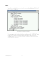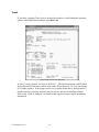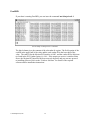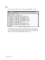
1
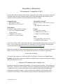
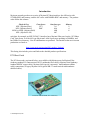
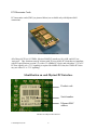
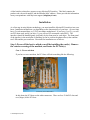
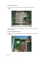
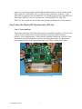
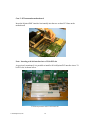
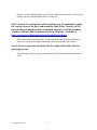
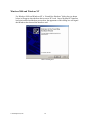
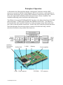
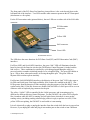
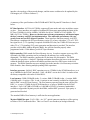
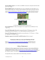
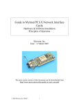
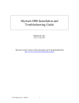
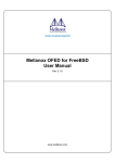
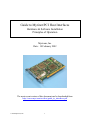
Guide to Myrinet/PCI Host Interfaces
Hardware & Software Installation
Principles of Operation
Myricom, Inc.
Date: 18 February 2002
The most recent version of this document can be downloaded from
http://www.myri.com/scs/doc/guide_to_interfaces.pdf
© 2002 Myricom, Inc.
1
Regulatory Information
Electromagnetic Compatibility (EMC)
Myrinet-Fiber (M3F), Myrinet-Serial (M3S), and Myrinet-LAN (M2L) host interfaces and their
associated cables are fully compliant with the following standards and specifications for the
emission of and susceptibility to electromagnetic interference (EMI):
European Union
➢ BS EN55024 (1998)
➢ BS EN55022 (1998) Class A
Australia/New Zealand
AS/NZS 3548 (w/A1 & A2 1997) Class A
using:
➢ BS EN55022 (1998) Class A
United States
FCC Part 15 Subpart B Class A using:
➢ FCC Part 15 Subpart B Section
15.109 Class A
➢ CISPR 22 (1997) Class A
➢ ANSI C63.4 (1992) method
Canada
ICES-003 Class A using:
➢ CISPR 22 (1997) Class A
➢ ANSI C63.4 (1992) method
Japan
VCCI (April 2000) Class A using:
➢ CISPR 22 (1997) Class A
On the basis of these EMC certifications and other engineering data, these products carry the CE
mark. A copy of the current Declaration of Conformity can be found linked from the product
specifications linked from http://www.myri.com/myrinet/full_product_list/.
Please note that Myrinet-SAN (M2M and M3M) host interfaces and their associated cables emit
EMI in excess of Class A levels, and so should be used only for “in cabinet” applications.
Laser Device Safety
The optical-fiber transceivers used in the M3F-PCI64 family of products are Class I Laser
Products. Optical-fiber components with this classification pose no threat of biological damage,
and are considered to be safe.
Disposal of Components that Contain Lead
Myrinet host interfaces contain small quantities of lead in the tin-lead solder. Please dispose of
them safely. Disposal of lead-containing electronic components through regular trash channels
is prohibited in many countries and regions, because the lead leached out of landfills may
contaminate groundwater supplies. Myricom has proper channels for the disposal of these
materials, and will dispose of any Myrinet products returned for that purpose to Myricom.
© 2002 Myricom, Inc.
2
Introduction
Myricom currently produces two series of Myrinet/PCI host interfaces: the 64B series with
133MHz RISC and memory, and the 64C series with 200MHz RISC and memory. The product
codes follow this scheme:
Physical Port
Form factor
M3F- (Myrinet-Fiber)
PCI
M3S- (Myrinet-Serial)
PMC
M2M- or M3M- (Myrinet-SAN)
M2L- (Myrinet-LAN)
Interface type
64
64A
64B
64C
Memory
-2
-4
-8
such that, for example, an M3F-PCI64C-2 interface has a Myrinet-Fiber port, has the “PCI Short
Card” form factor, is of the 64C type (Myricom LANai 9 processor operating at 200MHz), and
has 2MB of local memory. Not all combinations are produced. The interfaces that are in current
production are listed at:
http://www.myri.com/myrinet/full_product_list.html
This listing also includes prices and links to the detailed product specifications.
PCI Short Cards
The PCI short cards, as pictured below, are available with Myrinet ports for Myrinet-Fiber
(industry-standard LC-connectorized 50/125 multimode fiber cables), Myrinet-Serial (industrystandard HSSDC copper cable), Myrinet-SAN (special “microstrip” multiconductor ribbon
cable) connections, or legacy Myrinet-LAN (special DB-37-connectorized multiconductor
shielded cables).
PCI short card (PCI64B, fiber connector)
© 2002 Myricom, Inc.
3
PCI Mezzanine Cards
PCI mezzanine cards (PMC) (as pictured below) are available only with Myrinet-SAN
connections.
PCI mezzanine card (PMC64B)
All of these 64/32-bit, 66/33MHz, Myrinet-2000/PCI interfaces (64A, 64B, and 64C) are
“universal”. They function correctly in hosts with 32-bit or 64-bit PCI slots that are compliant
with PCI specifications (version 2.2), with a 33–66MHz PCI clock, and with either 3.3V or 5V
PCI-bus signal levels. (3.3V signaling is required for 66MHz PCI slots, but 33MHz PCI slots
may use either 5V or 3.3V signaling.)
Identification on each Myrinet/PCI interface
Product code
Serial number
Ethernet MAC
address
The label on a Myrinet/PCI interface
© 2002 Myricom, Inc.
4
A label similar to that above appears on any Myrinet/PCI interface. This label contains the
product code, the serial number, and the Ethernet MAC address. Please provide this information
in any correspondence with Myricom support ([email protected]).
Installation
As a first step in using Myrinet technology, you must install the Myrinet/PCI interfaces into your
hosts. Installation instructions vary depending on the characteristics of your host: (1) tower unit
host, (2) rack-mounted host, or (3) PCI mezzanine motherboard. If you have (1) or (2), you will
use PCI short cards, and if you have (3), you will use PCI mezzanine cards (PMC). The
interfaces should be handled gently, preferably by the front panel or card edges. The front panel
of the interface is the metal plate or molding (as can be seen on the photos above) that contains
two LEDs and the port connector. Directions for installation are as follows:
Step 1: Power off the host to which you will be installing the card(s). Remove
the exterior covering of the machine, and locate the PCI slot(s).
Case 1: Tower unit host
If you have a tower unit host, the PCI slots will look something like the following:
PCI slots (32-bit and 64-bit)
In this photo the PCI slots are the white connectors. There are four 32-bit PCI slots and
two (longer) 64-bit PCI slots.
© 2002 Myricom, Inc.
5
Case 2: Rack-mounted host
If you have a rack-mounted machine, the PCI slots will look something like the
following:
PCI slots (64-bit and 32-bit)
In this photo the PCI slots are the white connectors. There are two 64-bit PCI slots and
four 32-bit PCI slots.
Case 3: PCI mezzanine motherboard
If you have a PCI mezzanine motherboard, then the PCI slot should look something like
the following:
Photo of PCI mezzanine slot
© 2002 Myricom, Inc.
6
where you can see a previously installed Myrinet/PMC interface to the left of the circled
PMC connectors. 64-bit PMC slots or cards have three connectors, as shown. 32-bit
PMC slots or cards have just two connectors. It is alright to plug a 64-bit card (PMC64A,
PMC64B, or PMC64C) into a 32-bit slot, or a 32-bit card (PMC32A, PMC32B,
PMC32C) into a 64-bit slot, but in either case the card will function as a 32-bit interface.
Step 2: Insert the Myrinet/PCI interface into a PCI slot.
Case 1: Tower unit host
With a tower unit host, a PCI-short-card interface is installed vertically in a PCI slot. Any
of the PCI slots could be chosen for the installation of the Myrinet/PCI interface.
However, for best performance, a 64-bit interface should be installed in a 64-bit PCI slot.
Inasmuch as some PCI connectors are more close-fitting than others, you may need to
push quite hard on the front panel and the edge of the card to seat the card securely.
Inserting a PCI-short-card interface vertically
© 2002 Myricom, Inc.
7
Installed interface in a 64-bit PCI slot
Case 2: Rack-mounted host
Since space is very restricted in a rack-mounted unit, the Myrinet/PCI interface must be
installed with a riser card. The riser card is inserted on the PCI connector side of the
card, and the riser card is then inserted into a PCI slot (as shown in the following
photograph). Inasmuch as some PCI connectors are more close-fitting than others, you
may need to push quite hard on the front panel and the edge of the card to get the card to
seat securely.
Insertion of interface (with riser card) into a 64-bit PCI slot
© 2002 Myricom, Inc.
8
Caution: Although PCI riser cards are commonly used,
they will generally violate PCI specifications for the
length of signal traces. A riser card may also introduce
impedance discontinuities and signal degradation
between the mother board, riser card, and interface card.
If you observe PCI-communication errors when using a
riser card, see if the problem persists when you plug the
Myrinet/PCI interface directly into the PCI slot. A higher
quality riser card -- one whose traces match the
impedance of signals on the mother board and interface -may also solve the problem.
Also, it is important that a 64-bit riser card be used in a
64-bit PCI slot, and likewise a 32-bit riser card should be
used in a 32-bit PCI slot. Otherwise, the Myrinet/PCI
interface will not be correctly detected and/or serious
performance irregularities will result.
Any of these PCI slots could be chosen for the installation of your Myrinet/PCI interface.
However, for best performance, a 64-bit interface should be installed into a 64-bit PCI
slot.
Installed interface (with attached riser card)
© 2002 Myricom, Inc.
9
Case 3: PCI mezzanine motherboard
Insert the Myrinet/PMC interface horizontally into the two or three PCI slots on the
motherboard.
Inserting a PMC interface
Note: Inserting a 64-bit interface into a 32-bit PCI slot
As previously mentioned, it is possible to install a 64-bit Myrinet/PCI interface into a 32bit PCI slot, as shown below.
A 64-bit Myrinet/PCI card in a 32-bit PCI slot
© 2002 Myricom, Inc.
10
However, if this is done, the data path is 32 bits, and the 64-bit interface will be able to
transfer data only at half the data rate of a 64-bit slot.
Step 3: Secure the card in place with a locking screw (if applicable), replace
the exterior cover of the host, and attach the cable (Fiber, Serial, or SAN)
between the card and the switch (as detailed on pages 3-4 of the document
“Guide to Myrinet-2000 Switches and Switch Networks,” available at
http://www.myri.com/myrinet/m3switch/guide/index.html).
Please follow the instructions in the “Guide to Myrinet-2000 Switches and Switch
Networks” when connecting/disconnecting cables to/from cards and switches.
Step 4: Power on the host and check that the card is detected by the host
operating system.
Depending upon the operating system running on the host, this detection mechanism
varies.
© 2002 Myricom, Inc.
11
Linux
If your host is running Linux, you can issue the command /sbin/lspci, which will return
all devices attached to the PCI bus.
Screen image of /sbin/lspci command.
If the output you receive is similar to that above, namely you see the “MYRICOM Inc”
entry, the Myrinet/PCI interface has been correctly detected, and you can now proceed to
installing software. Refer to the “Guide to Software” for details of the required software
and for installation instructions.
© 2002 Myricom, Inc.
12
Solaris
If your host is running Solaris, you can issue the command /usr/sbin/prtconf, which will
print the system configuration.
Screen dump of /usr/sbin/prtconf command
If the output you receive is similar to that above, namely you see the “MYRICOM” entry,
the Myrinet/PCI interface has been correctly detected, and you can now proceed to
installing software. Refer to the “Guide to Software” for details of the required software
and for installation instructions.
© 2002 Myricom, Inc.
13
Tru64
If your host is running Tru64, prior to booting the machine, or after halting the operating
system, at the SRM console prompt, type show conf
Screen dump of show conf command
In Slot 13, under “Option” you will see 804314C1. This field contains the card ID, 8043,
for the Myrinet/PCI interface, and the card vendor ID for Myricom, 14C1 (as listed in the
PCI Vendor registry). If the output you receive is similar to that above, the Myrinet/PCI
interface has been correctly detected, and you can now proceed to installing software.
Refer to the “Guide to Software” for details of the required software and for installation
instructions.
© 2002 Myricom, Inc.
14
FreeBSD
If your host is running FreeBSD, you can issue the command /usr/sbin/pciconf -l.
Screen dump of /sbin/pciconf –l command
The third column gives the contents of the subvendor id register. The field consists of the
card ID in the upper half of the value and the card vendor ID in the lower half of the
value. The card ID for the Myrinet/PCI interface is 8043, and the vendor ID for Myricom
(as listed in the PCI Vendor registry) is 14c1. If the output you receive is similar to that
above, the Myrinet/PCI interface has been correctly detected, and you can now proceed
to installing software. Refer to the “Guide to Software” for details of the required
software and for installation instructions.
© 2002 Myricom, Inc.
15
IRIX
If your host is running IRIX, you can issue the command /sbin/hinv –v –c iobd.
Screen dump of /sbin/hinv command
The PCI adapters with vendor ID 5313 are Myrinet/PCI interfaces. If the output you
receive is similar to that above, the Myrinet/PCI interface has been correctly detected,
and you can now proceed to installing software. Refer to the “Guide to Software” for
details of the required software and for installation instructions.
© 2002 Myricom, Inc.
16
MacOS X
If your host is running MacOS X, you can issue the command ioreg, which will return all
devices attached to the PCI bus. An excerpt of the sample output is as follows:
<…>
||
||
||
||
| +-o USBKeyLargo <class USBKeyLargo>
+-o pci14c1,8043@12 <class IOPCIDevice>
| +-o gm <class gm>
+-o usb@18 <class IOPCIDevice>
<…>
If the output you receive contains the “8043” device, the Myrinet/PCI interface has been
correctly detected, and you can now proceed to installing software. Refer to the “Guide to
Software” for details of the required software and for installation instructions.
© 2002 Myricom, Inc.
17
Windows 2000 and Windows NT
For Windows 2000 and Windows NT, a “Found New Hardware” dialog box (as shown
below) will appear when the host detects a new PCI card. Once a Myrinet/PCI interface
has been installed and the host powered on, the appearance of this dialog box will signal
that Windows has detected the interface card.
Photo of Dialog Box
© 2002 Myricom, Inc.
18
Principles of Operation
As illustrated in the following block diagram, all Myrinet/PCI interfaces include a RISC
processor to execute the Myrinet Control Program (MCP), local memory, a packet interface to
and from the Myrinet port, and a versatile DMA controller to support zero-copy APIs. Each of
these parts support high-availability and data-integrity features, such as “heartbeat” linkcontinuity monitoring, packet checksums, and memory parity.
The difference between the PCI64B and PCI64C interfaces is the allowed clock rate of the RISC
and local memory: 133MHz for the PCI64B, and 200MHz for the PCI64C. The difference
between the Fiber, Serial, and SAN interfaces is in the conversion circuitry between the SAN
port of the LANai chip and the external port. For the Fiber (M3F) interface pictured and shown
in the block diagram, the conversion circuitry consists of a SerDes-SAN chip, a SerDes
(Serializer-Deserializer) chip, and the Fiber transceiver.
SerializerDeserializer
(SerDes)
SerDes-SAN
LANai
Memory
Power regulator
PCI64B card
LEDs
© 2002 Myricom, Inc.
Fiber connector
PCI-DMA
19
PCI connector
The front panel of the PCI-Short-Card interface pictured above is the vertical metal plate on the
left-hand side of the interface. Two LEDs and the cable connector penetrate this PCI front panel
(also known as a face plate).
For the PCI mezzanine cards (pictured below), the two LEDs are on either side of the SAN cable
connector.
PCI Mezzanine
connectors
Yellow LED
SAN connector
Green LED
PCI64B PMC interface
The LEDs have the same functions for PCI-Short-Card (PCI) and PCI-Mezzanine-Card (PMC)
interfaces.
For Fiber (M3F) and Serial (M3S) interfaces, the green “link” LED will illuminate when the
board is powered, the firmware (such as the GM Myrinet Control Program) is loaded, and the
link is active. These conditions are satisfied by a port being plugged through a cable to a
powered switch, to another initialized interface or to a loopback plug. The green LED blinks at
up to ~5Hz to show when packet traffic is flowing through the port. The green LEDs on
Myrinet-2000 switches operate similarly.
For Myrinet-SAN (M2M/M3M) interfaces, the behavior of the green “link” LED is the same as
for Fiber and Serial ports if the high-availability (HA) features are enabled in the MCP. (The
LED operates from the detection of link continuity using the presence of the HA BEAT control
symbol on the link.) If the HA features are disabled, the link LED of a SAN port will be on even
without a cable or loopback plug connected to the port.
The yellow “LANai” LED is controlled by the LANai processor, and its meaning may be
different for different Myrinet Control Programs. For the GM MCP, the yellow LED will pulse
like a heartbeat while the MCP is running, and will pulse faster when there is more packetsending activity (including sending acknowledge packets in reply to packets received.) If the
yellow LED is not pulsing, the GM MCP is not loaded or is not running.
It is safe electrically to plug or unplug the interface from the switch while the host is powered on.
However, if you unplug the cable and plug it into another port on the switch or into a different
© 2002 Myricom, Inc.
20
interface, the topology of the network changes, and the routes would need to be updated by the
GM mapper (see “Guide to Software”).
A summary of the specifications of the PCI64B and PCI64C Myrinet/PCI interfaces is listed
below:
PCI-bus Interface: 64/32-bit, 66/33MHz, supports all burst modes and write-invalidate, master
or slave. These interfaces are capable of sustained PCI data rates approaching the limits of the
PCI bus (528 MB/s for 64-bit, 66MHz; 264 MB/s for 64-bit, 33MHz or 32-bit, 66MHz; 132
MB/s for 32-bit, 33MHz). However, the data rate to/from system memory will depend upon
the host’s memory and PCI-bus implementation. The achievable performance can vary
greatly from one host PCI chipset to another. These interfaces function correctly in all PCI
slots that are compliant with PCI specifications version 2.2 or later, with either 3.3V or 5V PCIbus signal levels. (3.3V signaling is required of 66MHz PCI slots, but 33MHz PCI slots may use
either 5V or 3.3V signaling.) PCI parity generation and detection is provided. The interface
provides a 64-bit Base Address Register (BAR), but will also function properly when
programmed with a 32-bit address, per the PCI specifications.
DMA controller: DMA stands for Direct Memory Access. In order to support zero-copy APIs
efficiently, the DMA operations can be performed with arbitrary byte counts and byte
alignments. The DMA controller computes the IP checksum for each transfer. The DMA
controller also provides a “doorbell” signaling mechanism that allows the host to write anywhere
within the doorbell region, and have the address and data stored in a FIFO queue in the local
memory. The DMA controller traverses multiple lists in the interface’s local memory to initiate
DMA transfers, thus allowing multiple pending DMA operations.
Interface processor: LANai 9 RISC operating at up to 133MHz for the PCI64B interfaces, or at
up to 200MHz for the PCI64C interfaces. Note: the RISC core in the LANai 9 is similar to but
not binary-compatible with earlier LANai RISCs.
Local memory: 2MB (256Kx8B) in the –2 version; 4MB (512Kx8B) in the –4 version, 8MB
(1Mx8B) in the –8 version. (The –4 and –8 options are not currently available for all port types
and for PMC versus PCI form factors.) The local memory operates from the same clock as the
RISC, i.e., at up to 133MHz for the PCI64B interfaces, or at up to 200MHz for the PCI64C
interfaces. Up to 1,067 MB/s (PCI64B) or 1,600 MB/s (PCI64C) of memory bandwidth is
available to support the Myrinet port, the host DMA, and the RISC processor. Byte parity is
generated and checked.
The standard 2MB of local memory is sufficient for most applications.
Myrinet-2000-Fiber port: 2.0+2.0 Gb/s. An “LC” optical connector attaches to a fiber pair up
to 200m of 50/125 multi-node fiber. This is a Class I Laser Product (no biological hazard).
© 2002 Myricom, Inc.
21
Myrinet-2000-Serial port: 2.0+2.0 Gb/s at an HSSDC connector to a Myrinet Serial-Link cable
up to 10m in length.
Myrinet-2000-SAN port: The default data rate can be switched between SAN-2000 (2.0+2.0
Gb/s) and SAN-1280 (1.28+1.28 Gb/s) with a mechanical switch on the circuit board. The host
can over-ride the default data rate. The SAN port appears on the A link of the SAN connector
(refer to http://www.myri.com/myrinet/cables/m2m-cl.html for details); the B link is unused.
PCI Short card (switch positioned for SAN-2000 rate)
PCI Mezzanine card (switch positioned for SAN-2000 rate)
Physical dimensions: PCI Short Card: height 10.7cm, length 18.0cm, total thickness 2.5cm,
weight 120g.
Power (PCI Short card): The interface is powered from the 5V PCI power: 1.9A (9.5W)
maximum for the M3F-PCI64B-2; 2.2A (11.0W) maximum for the M3F-PCI64C-2.
Power (PCI Mezzanine card): The interface is powered from the 3.3V PCI power: ~4 Watts.
PCI Mezzanine Card (IEEE P1386.1).
Regulatory Approvals for the M3F- and M3S interfaces: Please see page 2.
Performance differences between PCI64B and PCI64C
Refer to http://www.myri.com/myrinet/performance/index.html for full details on the
application-level performance difference between the PCI64B and PCI64C interfaces.
Software Requirements
All Myricom software support for the PCI64 family of interfaces is based on the GM Myrinet
Control Program and the GM API. For details about GM, please refer to “The GM Message
Passing System” document available at http://www.myri.com/scs/GM/doc/gm_toc.html. Refer to
the “Guide to Software” for details of the available software and for installation instructions.
The MyriAPI software is not available for the PCI64 family of interfaces.
© 2002 Myricom, Inc.
22