1
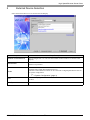
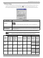
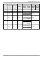
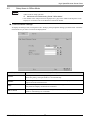
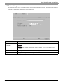
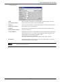
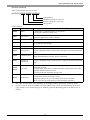
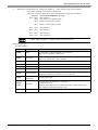
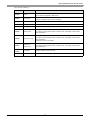
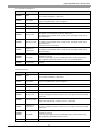
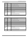
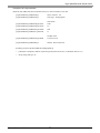
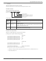
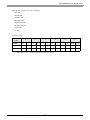
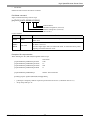
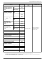
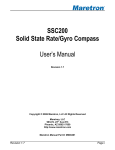
YASKAWA Electric Corporation High Speed Ethernet Server Driver 1 System Configuration....................................................................................................... 3 2 External Device Selection ................................................................................................ 4 3 Communication Settings .................................................................................................. 5 4 Setup Items ...................................................................................................................... 7 5 Supported Devices......................................................................................................... 12 6 Device Code and Address Code.................................................................................... 28 7 Error Messages.............................................................................................................. 31 1 High Speed Ethernet Server Driver Introduction This manual describes how to connect the Display and the External Device (target robot). In this manual, the connection procedure will be described in the sections identified below: 1 System Configuration This section lists the types of External Devices and SIO that you can connect. "1 System Configuration" (page 3) 2 External Device Selection Select a model (series) of the External Device and its connection method. "2 External Device Selection" (page 4) 3 Communication Settings This section shows setting examples for communicating between the Display and the External Device. "3 Communication Settings" (page 5) 4 Setup Items This section describes communication setup items on the Display. Set the Display’s communication settings in GP Pro-EX or in off-line mode. "4 Setup Items" (page 7) Operation GP-Pro EX Device/PLC Connection Manual 2 High Speed Ethernet Server Driver 1 System Configuration The system configuration in the case when the External Device of Yaskawa Electric Corporation and the Display are connected is shown. Series CPU Link I/F SIO Type Setting Example DX100 DX100 LAN port on the controller Ethernet (UDP) "Setting Example 1" (page 5) FS100 FS100 Ethernet port on the controller Ethernet (UDP) "Setting Example 1" (page 5) DX200 DX200 LAN port on the controller Ethernet (UDP) "Setting Example 1" (page 5) FS100L FS100L Ethernet port on the controller Ethernet (UDP) "Setting Example 1" (page 5) • Available Classes vary depending on the software version of the External Device. Please contact the Yaskawa Electric Corporation for the more information. YASKAWA Electric Corporation Robotics Division Telephone: +81-93-645-7703 Facsimile: +81-93-631-8140 Connection Configuration • 1:1 Connection External Device Display HUB • 1:n Connection Maximum number of External Devices: 64 *1 External Device Display External Device HUB *1 When 33 or more External Devices are connected, it is necessary to check [Increase allowable number of Devices/PLCs]. "4.1 Setup Items in GP-Pro EX" (page 7) GP-Pro EX Device/PLC Connection Manual 3 High Speed Ethernet Server Driver 2 External Device Selection Select the External Device to be connected to the Display. Setup Items Setup Description Number of Devices/PLCs Use an integer from 1 to 4 to enter the number of Devices/PLCs to connect to the display. Manufacturer Select the manufacturer of the External Device to be connected. Select "YASKAWA Electric Corporation". Series Select a model (series) of the External Device to be connected and connection method. Select "High Speed Ethernet Server". Check the External Device which can be connected in "High Speed Ethernet Server" in system configuration. "1 System Configuration" (page 3) Port Select the Display port to be connected to the External Device. Select "Ethernet (UDP)". Use System Area Not available in this driver. GP-Pro EX Device/PLC Connection Manual 4 High Speed Ethernet Server Driver 3 Communication Settings Examples of communication settings of the Display and the External Device, recommended by Pro-face, are shown. 3.1 Setting Example 1 Settings of GP-Pro EX Communication Settings To display the setup screen, from the [Project] menu, point to [System Settings] and select [Device/PLC]. • Because it may take some time for file operation processing, "20" (sec.) is specified for a default of "Timeout." Even if the External Device does not respond, therefore, it takes 20 seconds until the Timeout is detected. Adjust the Timeout value while checking the actual communication status. GP-Pro EX Device/PLC Connection Manual 5 High Speed Ethernet Server Driver Device Setting To display the [Individual Device Settings] dialog box, from [Device-Specific Settings] in the [Device/PLC] window, select the External Device and click [Settings] . To connect multiple External Devices, from [Device-Specific Settings] in the [Device/PLC] window, click [Add Device] to add another External Device. • Default IP address of the External Device is as follows. DX100 series: 192.168.255.1 FS100 series: 10.0.0.2 • Check with a network administrator about IP address. • Do not set the duplicate IP address in the same network. • Set IP address and Port Number on the External Device in the [Individual Device Settings] dialog box. • You need to set IP address on the Display in offline mode. Settings of External Device Please contact the Yaskawa Electric Corporation for the communication settings of the External Device. Check the set IP address in the next procedure. 1 2 Change the security mode to "management mode". Select [NETWORK SERVICE] from [SYSTEM INFO] of main menu. GP-Pro EX Device/PLC Connection Manual 6 High Speed Ethernet Server Driver 4 Setup Items Set up the Display’s communication settings in GP Pro-EX or in the Display’s off-line mode. The setting of each parameter must match that of the External Device. "3 Communication Settings" (page 5) • Set the Display’s IP address in off-line mode. Cf. 4.1 Maintenance/Troubleshooting Guide "Ethernet Settings" Setup Items in GP-Pro EX Communication Settings To display the setup screen, from the [Project] menu, point to [System Settings] and select [Device/PLC]. Setup Items Setup Description Port No. Enter a port number of the Display, using 1024 to 65535. Check into [Auto], and a port number is set automatically. Timeout Use an integer from 1 to 127 to enter the time (s) for which the Display waits for the response from the External Device. Retry In case of no response from the External Device, use an integer from 0 to 255 to enter how many times the Display retransmits the command. Wait To Send Use an integer from 0 to 255 to enter standby time (ms) for the Display from receiving packets to transmitting next commands. When clicked, the [Increase Allowable Number of Devices/PLCs] dialog box is displayed. When you check [Increase allowable number of Devices/PLCs], the settings for [Allowable Number of Devices/PLCs] can be extended to "64". Increase Allowable Number of Devices/ PLCs • Refer to the GP-Pro EX Reference Manual for Indirect Device. Cf. GP-Pro EX Reference Manual "Changing the Device/PLC at Runtime (Indirect Device)" GP-Pro EX Device/PLC Connection Manual 7 High Speed Ethernet Server Driver Device Setting To display the [Individual Device Settings] dialog box, from [Device-Specific Settings] in the [Device/PLC] window, select the External Device and click [Settings] . To connect multiple External Devices, from [Device-Specific Settings] in the [Device/PLC] window, click [Add Device] to add another External Device. Setup Items Setup Description Set IP address of the External Device. IP Address • Check with a network administrator about IP address. Do not set the duplicate IP address. Port No. Enter a port number of the External Device, using 1024 to 65534. Use Multiple Read / Write Command If read / write to the multiple points at the same time, select the [Use Multiple Read / Write Command] check box. • Enter a check in the box of [Use Multiple Read/Write Command], and the following changes are made. • When a check is removed, only the class ID is changed. The device that was changed to "undefined" by entering a check stays "undefined" even if the check is removed. Class ID Class Name I/O data Before the change (Single Read / Write) 0x078 Attribute After the change (Multiple Read / Write) 0x300 Instance Before the change No change 00 - 63 After the change 0 Register data 0x079 0x301 No change 00 - 63 0 B 0x07A 0x302 No change 00 - 63 0 I 0x07B 0x303 No change 00 - 63 0 GP-Pro EX Device/PLC Connection Manual 8 Bit Before the change After the change 00 - 07 No change More than 08 undefined 00 - 07 No change More than 08 undefined 00 - 15 No change More than 16 undefined 00 - 15 No change More than 16 undefined High Speed Ethernet Server Driver Class ID Class Name Before the change (Single Read / Write) Attribute After the change (Multiple Read / Write) Instance Before the change After the change Bit Before the change D 0x07C 0x304 No change 00 - 63 0 No change R 0x07D 0x305 No change 00 - 63 0 No change 0 1 1-4 No change S 0x07E 0x306 No change No change More than 5 undefined P BP EX 0x07F 0x080 0x081 0x307 0x308 0x309 No change No change No change GP-Pro EX Device/PLC Connection Manual 9 0 1 1 - 13 No change More than 14 undefined 0 1 1-9 No change More than 10 undefined 0 1 1-9 No change More than 10 undefined No change No change No change After the change High Speed Ethernet Server Driver 4.2 Setup Items in Offline Mode • Please refer to Maintenance/Troubleshooting Guide for more information on how to enter offline mode or about operation. Cf. Maintenance/Troubleshooting Guide "Offline Mode" • The number of the setup items to be displayed for 1 page in the offline mode depends on the Display in use. Please refer to the Reference manual for details. Communication Settings To display the setting screen, touch [Device/PLC Settings] from [Peripheral Settings] in offline mode. Touch the External Device you want to set from the displayed list. Setup Items Setup Description Port No. Enter a port number of the Display, using 1024 to 65535. Check into [Auto], and a port number is set automatically. Timeout Use an integer from 1 to 127 to enter the time (s) for which the Display waits for the response from the External Device. Retry In case of no response from the External Device, use an integer from 0 to 255 to enter how many times the Display retransmits the command. Wait To Send Use an integer from 0 to 255 to enter standby time (ms) for the Display from receiving packets to transmitting next commands. GP-Pro EX Device/PLC Connection Manual 10 High Speed Ethernet Server Driver Device Setting To display the setting screen, touch [Device/PLC Settings] from [Peripheral Settings]. Touch the External Device you want to set from the displayed list, and touch [Device]. Setup Items Setup Description Set IP address of the External Device. IP Address • Check with a network administrator about IP address. Do not set the duplicate IP address. Port No. Enter a port number of the External Device, using 1024 to 65534. Multiple Read / Write Display whether perform the Multiple Read / Write. GP-Pro EX Device/PLC Connection Manual 11 High Speed Ethernet Server Driver 5 Supported Devices Range of supported device address is shown in the table below. Please note that the actually supported range of the devices varies depending on the External Device to be used. Please check the actual range in the manual of your connecting equipment. Enter the External Device address in the dialog box below. • For word addresses Class (Command number) Select the class of the object to send messages. If [Direct Input] is selected, input a class code of "0000 - FFFF" (hexadecimal). Instance (Data array number) Input the instance number (a decimal from 00000 - 16383) that defines which class instance receives the message. Attribute (Data element number) Input the value (a decimal from 00 - 63) that defines which attribute of the instance is accessed. Control Address Depending on the class, a control address will be needed that instructs the data target for expansion, etc. In such an event, input the foremost position of the control address with a decimal from 0000 - 4095. Only the user area can be designated For classes that do not require control addresses, this value is ignored. • If "Set as Default Value" is checked, when a new address is input the configured value will be displayed as the default value. GP-Pro EX Device/PLC Connection Manual 12 High Speed Ethernet Server Driver • For bit addresses Class (Command number) Select the class of the object to send messages. If [Direct Input] is selected, input a class code of "0000 - FFFF" (hexadecimal). Instance (Data array number) Input the instance number (a decimal from 00000 - 16383) that defines which class instance receives the message. Attribute (Data element number) Input the value (a decimal from 00 - 63) that defines which attribute of the instance is accessed. Control Address Depending on the class, a control address will be needed that instructs the data target for expansion, etc. In such an event, input the foremost position of the control address with a decimal from 0000 - 4095. Only the user area can be designated For classes that do not require control addresses, this value is ignored. Bit Number Input the bit position you want to get / write via a decimal (00 - 31) from the word data designated to the attribute. • If "Set as Default Value" is checked, when a new address is input the configured value will be displayed as the default value. GP-Pro EX Device/PLC Connection Manual 13 High Speed Ethernet Server Driver Device Class Instance Attribute Control Bit Bit address Word address Class: 0000h - FFFFh Instance: 00000 - 16383 Attribute: 00 - 63 Control address: 0000 - 4095 Bit: 0 - 31 32 bits Class: 0000h - FFFFh Instance: 00000 - 16383 Attribute: 00 - 63 Control address: 0000 - 4095 or Comments *2 *1 *1 The high and low relationship of the stored data varies depending on the External Device. Refer to your External Device manual for details. *2 The usable system area designation on the connection device is only the load area size. The usable size for the load area differs depending on the object designated. • Please refer to the manual of the External Device for more details of the device. The device name notation differs in the manual of the GP-Pro EX and the External Device. GP-Pro EX External Device Class Command No. Instance Instance Attribute Attribute • Not supported in sequential address designation / indirect address designation / offset address designation. Data behavior, when designated, is indeterminate. (The address increment and changed portion is reflected in Control) • Please refer to the precautions on manual notation for icons in the table. "Manual Symbols and Terminology" The address input area is shown below. • For word addresses (0070,00001,01,0000) Control address*1 Attribute Instance Class *1 Not used if the command type is robot control (Class other than 0x04C0 to 0x04C3). (0000: reserved) GP-Pro EX Device/PLC Connection Manual 14 High Speed Ethernet Server Driver • For bit addresses (0070,00001,01,0000)/0 Bit position Control address*1 Attribute Instance Class *1 Not used if the command type is robot control (Class other than 0x04C0 to 0x04C3). (0000: reserved) GP-Pro EX Device/PLC Connection Manual 15 High Speed Ethernet Server Driver File Control Commands File control command are commands for sending and receiving with a robot controller in file units. Designate the following classes and execute. Process Class Data direction File read 0x4C0 External Device Display File write 0x4C1 Display External Device File list 0x4C2 External Device Display File delete 0x4C3 Display External Device • Class 0x4C0 to 0x4C3 is Virtual Class. The class of corresponding External Device is 0x0. • File control commands can only execute D script. • The control address of the file control command can specify only USR area. (USR0000 USR4095) • File Read Loads the designated file from the robotic controller into Display. The loaded file data is either saved on a external storage or stored in a Display internal device. File Type and Structure The following are the types of files for loading. File Type Data to read Job program files (*.JBI) Extracts the "NOP" - "END" range from the job program file that is read out. Tool info files (TOOL.CND) Extracts information about Tool 0 - Tool 63. Tool data is read out for the 15 items of TOOL Name and Data0 - Data13 for each Tool number. IO comment files (IONAME.DAT) Reads out comments in 4-bit units. Text files (*.PRM,*.LST) Saves data that is read out in an as-is format. The starting read line and the number of read lines can be designated. (Up to CRLF is counted as 1 line) Binary files Saves data that is read out in an as-is format. Cannot designate the starting read line and the number of read lines. One time data backup (CMOSBK.BIN) Saves data that is read out in an as-is format. GP-Pro EX Device/PLC Connection Manual 16 High Speed Ethernet Server Driver File Read Command Inputs commands directly from D script. [w:[PLC1](04C0,00000,00,0000)] Control address Attribute: Designate 0 (reserved) Instance: Designate 0 (reserved) Class: 0x4C0 Control address Address Item Details +0000 Status 0: Initial value, 1: Run instruction, 16: In-process, 256: Normal completion, 4096: Error +0001 Line count Number of lines in the obtained file Protocol is updated after send is complete. +0002 Save location*1*2 0: Memory, 1: CF/SD, 3: USB +0003 File type 1: Job program, 2: Tool info file, 3: IO comment file, 4: Text file, 5: Binary file, 6: One time data backup +0004 Starting address USER area address for the output destination +0005 Starting line*3 File list output starting line 0 - 4999 If a line is designated where no data exists, the output result will be filled with 0x00. +0006 Character count Maximum number of characters on each line Filled with 0x00 during overflow. Excess is truncated. +0007 Number of output lines Number of output file names 1 - 5000 If a line is designated where no data exists, the output result will be filled with 0x00. File name Load file name (Max. 32 characters + extension) 18 Word is reserved. Overflow digits (Byte units) are filled with 0x00, or 0x00 unnecessary when inputting maximum character count. Also used as the file name when saving to CF Folder name Path name of save location (Max. 64 characters) Variable length Set 0x00 at the end of the character string. Designated when saving to CF or loading from CF into controller. (There is no concept of the directory in the load target controller.) +0008 +0025 +0026 *1 The usable external strage varies depending on the Display. Refer to the Display manual for details. *2 Saving to external strage is available only select [Binary file] or [One time data backup] in the [File type]. Unable to save in other file types. In addition, [One time data backup] will not be able to save on memory. GP-Pro EX Device/PLC Connection Manual 17 High Speed Ethernet Server Driver *3 Starting line: Designate the file starting line number (0 - ) when storing in GP internal memory. * The CRLF in the file is used as the line delimiter. However, the line numbers when Tool info is selected in [Type] are as follows. Tool info: Tool number designation (0 - 63) 0001 - 0015: Tool number 0 0001: Tool Name (Text data 20 bytes) 0002: Data0 (2 words [float 32-bit]) : 0015: Data13 (2 words [float 32-bit]) 0101 - 0115: 0201 - 0215: : 0301 - 0315: 6301 - 6315: Tool number 1 Tool number 2 Tool number 3 Tool number 63 • When displaying Data0 -, a [Signed Float 32-bit] is necessary. Settings by file type Job file (memory) Address Item Details +0000 Status 0: Initial value, 1: Run instruction, 16: In-process, 256: Normal completion, 4096: Error +0001 Line count Number of lines in the obtained file Protocol is updated after send is complete. +0002 Save location 0: Memory +0003 File type 1: Job program +0004 Starting address USER area address for the output destination +0005 Starting line Ignored (0 reserved) +0006 Character count Maximum number of characters on each line Filled with 0x00 during overflow. Excess is truncated +0007 Number of output lines Ignored (0 reserved) +0008 +0025 File name File name (Max. 32 characters + extension) 18 Word is reserved. Overflow digits (Byte units) are filled with 0x00, or 0x00 unnecessary when inputting maximum character count. +0026 Folder name Ignored GP-Pro EX Device/PLC Connection Manual 18 High Speed Ethernet Server Driver Tool info file (memory) Address Item Details +0000 Status 0: Initial value, 1: Run instruction, 16: In-process, 256: Normal completion, 4096: Error +0001 Line count Number of lines in the obtained file Protocol is updated after send is complete. +0002 Save location 0: Memory +0003 File type 2: Tool info file +0004 Starting address USER area address for the output destination +0005 Starting line Starting Tool number 0 - 63 If a number is designated where no data exists, the output result will be filled with 0x00. +0006 Character count Ignored (20-byte reserved) If a number is designated where no data exists, the output result will be filled with 0x00. Overflow Excess is truncated. +0007 Number of output lines Number of tools to load 1 - 64 If a number is designated where no data exists, the output result will be filled with 0x00. +0008 +0025 File name Ignored (TOOL.CND reserved) +0026 Folder name Ignored GP-Pro EX Device/PLC Connection Manual 19 High Speed Ethernet Server Driver IO comment file (Memory) Address Item Details +0000 Status 0: Initial value, 1: Run instruction, 16: In-process, 256: Normal completion, 4096: Error +0001 Line count Number of lines in the obtained file Protocol is updated after send is complete. +0002 Save location 0: Memory +0003 File type 3: IO comment file +0004 Starting address USER area address for the output destination Starting line Comment number 0 - (4bit/1unit) (Ex: IN#1 is in Line No.0 , IN#5 is in Line No.1) If a number is designated where no data exists, the output result will be filled with 0x00. +0006 Character count Maximum number of characters on each comment. If a number is designated where no data exists, the output result will be filled with 0x00. Overflow Excess is truncated. +0007 Number of output lines Load comment number 1 - (4bit/1unit) If a number is designated where no data exists, the output result will be filled with 0x00. +0008 +0025 File name File name (Max. 32 characters + extension) 18 Word is reserved. Overflow digits (Byte units) are filled with 0x00, or 0x00 unnecessary when inputting maximum character count. (Ex: IONAME.DAT) +0026 Folder name Ignored +0005 Text file (memory) Address Item Details +0000 Status 0: Initial value, 1: Run instruction, 16: In-process, 256: Normal completion, 4096: Error +0001 Line count Number of lines in the obtained file Protocol is updated after send is complete. +0002 Save location 0: Memory +0003 File type 4: Text file +0004 Starting address USER area address for the output destination +0005 Starting line File list output starting line 0 - 4999 If a line is designated where no data exists, the output result will be filled with 0x00. +0006 Character count Maximum number of characters on each line Filled with 0x00 during overflow. Excess is truncated. +0007 Number of output lines Number of output file names 1 - 5000 If a line is designated where no data exists, the output result will be filled with 0x00. +0008 +0025 File name File name (Max. 32 characters + extension) 18 Word is reserved. Overflow digits (Byte units) are filled with 0x00, or 0x00 unnecessary when inputting maximum character count. +0026 Folder name Ignored GP-Pro EX Device/PLC Connection Manual 20 High Speed Ethernet Server Driver Binary file (memory) Address Item Details +0000 Status 0: Initial value, 1: Run instruction, 16: In-process, 256: Normal completion, 4096: Error +0001 Line count Number of lines in the obtained file Protocol is updated after send is complete. +0002 Save location 0: Memory +0003 File type 5: Binary file +0004 Starting address USER area address for the output destination +0005 Starting line Ignored (0 reserved) +0006 Character count Ignored (0 reserved) +0007 Number of output lines Ignored (0 reserved) +0008 +0025 File name Load file name (Max. 32 characters + extension) 18 Word is reserved. Overflow digits (Byte units) are filled with 0x00, or 0x00 unnecessary when inputting maximum character count. Also used as the file name when saving to CF. +0026 Folder name Ignored Binary file (CF/SD/USB) Address Item Details +0000 Status 0: Initial value, 1: Run instruction, 16: In-process, 256: Normal completion, 4096: Error +0001 Line count Number of lines in the obtained file Protocol is updated after send is complete. +0002 Save location 1: CF/SD, 3: USB +0003 File type 5: Binary file +0004 Starting address Ignored (0 reserved) +0005 Starting line Ignored (0 reserved) +0006 Character count Ignored (0 reserved) +0007 Number of output lines Ignored (0 reserved) +0008 +0025 File name Load file name (Max. 32 characters + extension) 18 Word is reserved. Overflow digits (Byte units) are filled with 0x00, or 0x00 unnecessary when inputting maximum character count. Also used as the file name when saving to CF. +0026 Folder name Path name of save location (Max. 64 characters) Variable length Set 0x00 at the end of the character string. GP-Pro EX Device/PLC Connection Manual 21 High Speed Ethernet Server Driver One time data backup (CF/SD/USB) Address Item Details +0000 Status 0: Initial value, 1: Run instruction, 16: In-process, 256: Normal completion, 4096: Error +0001 Line count File Size in kBytes (Max 64MB) +0002 Save location 1: CF/SD, 3: USB +0003 File type 6: One Time Data Backup +0004 Starting address Ignored (0 reserved) +0005 Starting line Ignored (0 reserved) +0006 Character count Ignored (0 reserved) +0007 Number of output lines Ignored (0 reserved) +0008 +0025 File name Ignored (CMOSBK.BIN reserved) +0026 - Folder name Path name of save location (Max. 64 characters) Variable length Set 0x00 at the end of the character string. • It may take some time to run the [One time data backup]. Please note that other tasks can not be performed because in [One time data backup]. GP-Pro EX Device/PLC Connection Manual 22 High Speed Ethernet Server Driver Example of D script execution Read Job file (ABC.JBI) from controller and save to the root folder of CF card [w:[#INTERNAL]USR01002]=1 [w:[#INTERNAL]USR01003]=1 // Save location : CF // File type : JOB program [w:[#INTERNAL]USR01008]=0x4241 [w:[#INTERNAL]USR01009]=0x2E43 [w:[#INTERNAL]USR01010]=0x424A [w:[#INTERNAL]USR01011]=0x0049 // File name // AB // C. // JB // I [w:[#INTERNAL]USR01026]=0x0000 // Folder name // (NULL=root) [w:[#INTERNAL]USR01000]=1 // Status : Run instruction [t:0000]= [w:[PLC1](04C0,00000,00,1000)]#[t:0001] • [t:0000] is a temporary address required to perform the file access. (Undefined value is set.) • Set up the [t:0001] to "0". GP-Pro EX Device/PLC Connection Manual 23 High Speed Ethernet Server Driver • File Write Writes the designated file to the robotic controller. Designates the file data to be written and the file being stored in the CF card. File Write command Inputs commands directly from D script. [w:[PLC1](04C1,00000,00,0000)] Control address Attribute: Designate 0 (reserved) Instance: Designate 0 (reserved) Class: 0x4C1 Control address Address Item Details Status 0: Initial value, 1: Run instruction, 16: In-process, 256: Normal completion, 4096: Error +0001 +0018 File name File name (Max. 32 characters + extension) 18 Word is reserved. Overflow digits (Byte units) are filled with 0x00, or 0x00 unnecessary when inputting maximum character count. +0019 Folder name Path name (Max. 64 characters) Variable length Set 0x00 at the end of the character string. +0000 Example of D script execution Read Job (\123\ABC.JBI) from CF card and write controller. [t:0000]=[w:[PLC1](04C1,0000,00,1000)]# [t:0001] [w:[#INTERNAL]USR01001]=0x4241 [w:[#INTERNAL]USR01002]=0x2E43 [w:[#INTERNAL]USR01003]=0x424A [w:[#INTERNAL]USR01004]=0x0049 // File name // AB // C. // JB // I [w:[#INTERNAL]USR01019]=0x3231 [w:[#INTERNAL]USR01020]=0x0033 // Folder name // 12 // 3 [w:[#INTERNAL]USR01000]=1 // Status : Run instruction [t:0000]=[w:[PLC1](04C1,00000,00,1000)]#[t:0001] • [t:0000] is a temporary address required to perform the file access. (Undefined value is set.) • Set up the [t:0001] to "0". GP-Pro EX Device/PLC Connection Manual 24 High Speed Ethernet Server Driver • File List Loads a list of files stored in the robotic controller. The loaded file list is stored in the designated address. File List command Inputs commands directly from D script. [w:[PLC1](04C2,00000,00,0000)] Control address Attribute: Designate 0 (reserved) Instance: Designate 0 (reserved) Class: 0x4C2 Control address Address Item Details +0000 Status 0: Initial value, 1: Run instruction, 16: In-process, 256: Normal completion, 4096: Error +0001 List count The number of obtained lists Number of files of the file type unit that was read out. (Not the number of outputs.) +0002 File type 0: *.* 1: *.JBI 2: *.DAT 4: *.PRM 5: *.SYS 6: *.LST +0003 Starting address USER area address for the output destination +0004 Starting line File list output starting line 0 - 4999 If a line is designated where no data exists, the output result will be filled with 0x00. +0005 Character count Maximum number of characters on each line Filled with 0x00 during overflow. Excess is truncated. +0006 Output count Number of output file names 1 - 5000 If a number of lines are designated where no data exists, the output result will be filled with 0x00. JBI file list DAT file list PRM file list SYS file list LST file list Example of D script execution Load 3 places from the 7th position, and store in USR10000 . with a file name of maximum 12 characters [w:[#INTERNAL]USR01002]=1 [w:[#INTERNAL]USR01003]=10000 [w:[#INTERNAL]USR01004]=6 [w:[#INTERNAL]USR01005]=12 [w:[#INTERNAL]USR01006]=3 // File type : JOB program // Starting address : JOB program // Starting line // Character count // Output count [w:[#INTERNAL]USR01000]=1 // Status : Run instruction [t:0000]=[w:[PLC1](04C2,00000,00,1000)]#[t:0001] • [t:0000] is a temporary address required to perform the file access. (Undefined value is set.) • Set up the [t:0001] to "0". GP-Pro EX Device/PLC Connection Manual 25 High Speed Ethernet Server Driver When the file present is one of the following ABC.JBI ABCDE.JBI ABCDEF.JBI ABCDEFG.JBI ABCDEFGH.JBI ABCDEFGHI.JBI 123456.JBI AA.JBI Execution results Address (USR) 0 1 2 3 4 5 10000 2 1 4 3 6 5 J . I B 0x0 0x0 10006 A A J . I B 0x0 0x0 0x0 0x0 0x0 0x0 10012 0x0 0x0 0x0 0x0 0x0 0x0 0x0 0x0 0x0 0x0 0x0 0x0 • Data with a "0x" is a numerical value, and without is ASCII. GP-Pro EX Device/PLC Connection Manual 26 High Speed Ethernet Server Driver • File Delete Deletes the file stored in the robotic controller. File Delete command Inputs commands directly from D script. [w:[PLC1](04C3,00000,00,0000)] Control address Attribute: Designate 0 (reserved) Instance: Designate 0 (reserved) Class: 0x4C3 Control address Address +0000 +0001 +0018 Item Details Status 0: Initial value, 1: Run instruction, 16: In-process, 256: Normal completion, 4096: Error File name File name (Max. 32 characters + extension) 18 Word is reserved. Overflow digits (Byte units) are filled with 0x00, or 0x00 unnecessary when inputting maximum character count. Example of D script execution When deleting the file (ABC.JBI) designated with D script [w:[#INTERNAL]USR01001]=0x4241 [w:[#INTERNAL]USR01002]=0x2E43 [w:[#INTERNAL]USR01003]=0x424A [w:[#INTERNAL]USR01004]=0x0049 // File name // AB // C. // JB // I [w:[#INTERNAL]USR01000]=1 // Status : Run instruction [t:0000]=[w:[PLC1](04C3,00000,00,1000)]#[t:0001] • [t:0000] is a temporary address required to perform the file access. (Undefined value is set.) • Set up the [t:0001] to "0". GP-Pro EX Device/PLC Connection Manual 27 High Speed Ethernet Server Driver 6 Device Code and Address Code Use device code and address code when you select "Device Type & Address" for the address type in data displays. Device Device Name Alarm data reading 0x70 Alarm history reading 0x71 Alarm data reading (for applying the sub code character strings) 0x30A Alarm history reading (for applying the sub code character strings) 0x30B Status information reading 0x72 Executing job information reading 0x73 Axis configuration ingormation reading 0x74 Robot position data reading 0x75 Position error reading 0x76 Torque data reading 0x77 Single Read / Write 0x78 Multiple Read / Write*2 0x300 Single Read / Write 0x79 Multiple Read / Write*2 0x301 Single Read / Write 0x7A Multiple Read / Write*2 0x302 Single Read / Write 0x7B Multiple Read / Write*2 0x303 Single Read / Write 0x7C Multiple Read / Write*2 0x304 Single Read / Write 0x7D Multiple Read / Write*2 0x305 GP-Pro EX Device/PLC Connection Manual 28 I/O data reading / writing*1 Register data reading / writing*3 Byte variable (B) reading / writing*1 Integer type variable (I) reading / writing*3 Double precision integer type variable (D) reading / writing Real type variable (R) reading /writing Device Code (HEX) Class code value Address Code (Instance*0x40000) + (Attribute*0x1000) + (Control) value High Speed Ethernet Server Driver Device Character type variable (S) reading /writing (16 bytes) *4 *5 *6 Character type variable (S) reading /writing (32 bytes) *4 *5 *7 Robot position type variable (P) reading / writing*4 *8 Base position type variable (BP) reading / writing*4 *8 External axis type variable (EX) reading / writing*4 *8 Device Name Single Read / Write 0x7E Multiple Read / Write 0x306 Single Read / Write 0x8C Multiple Read / Write 0x30C Single Read / Write 0x7F Multiple Read / Write 0x307 Single Read / Write 0x80 Multiple Read / Write 0x308 Single Read / Write 0x81 Multiple Read / Write 0x309 Alarm reset / error cancel 0x82 HOLD / servo ON/OFF 0x83 Step / cycle / continuous switching 0x84 Character string display command to the programming pendant 0x85 Start-up (job START) 0x86 Job select 0x87 Management time acquiring 0x88 System information acquiring 0x89 Move instruction command (Type Cartesian coordinates) 0x8A Move instruction command (Type Pulse) 0x8B File Read 0x4C0 File Write 0x4C1 File List 0x4C2 File Delete 0x4C3 *1 Device Code (HEX) Class code value Address Code (Instance*0x40000) + (Attribute*0x1000) + (Control) value The Display is 32 bit data, but the External Device is 8 bit data. Therefore, only low 8 bit data is valid. In the case that data is read from the External Device, data except for low 8 bits becomes zero. 3 or more odd-numbered points cannot be written at once by Multiple Write. Split the odd-numbered points to be written into even-numbered points + 1 point to write. GP-Pro EX Device/PLC Connection Manual 29 High Speed Ethernet Server Driver *2 When entering a check in the box of [Use Multiple Read/Write Command] in the [Individual Device Settings], it corresponds to the device monitor. Other classes and cases where a check has not been entered do not correspond to the device monitor. *3 The Display is 32 bit data, but the External Device is 16 bit data. Therefore, only low 16 bit data is valid. In the case that data is read from the External Device, data except for low 16 bits becomes zero. *4 If multiple points writing the S device, the P device, the BP device and the EX device, please use the memcpy command. The points can be specified are as follows. S device: Multiples of 16 (Example: 16 points, 32 points, 48 points, etc.) P device: 13 points BP device: 9 points EX device: 9 points *5 The Multiple Read/Write attribute of the External Device is fixed to zero. To specify with the Display, set to "1". *6 Can be used for the External Devices except for DX200 series. *7 Can be used for DX200 series only. *8 When the [Use Multiple Read/Write Command] is selected, set the same attribute as the Single Read/Write of the same device. Refer to the External Device Manual for the content of the attribute. • When using a class that is not supported by the driver, no error occurs with the GP-Pro EX. If project transfer to the Display and restart are conducted, an improper device error occurs. GP-Pro EX Device/PLC Connection Manual 30 High Speed Ethernet Server Driver 7 Error Messages Error messages are displayed on the screen of Display as follows: "No. : Device Name: Error Message (Error Occurrence Area)". Each description is shown below. Item Description No. Error No. Device Name Name of External Device where error occurs. Device name is a title of External Device set with GP-Pro EX. (Initial value [PLC1]) Error Message Displays messages related to the error which occurs. Displays IP address or device address of External Device where error occurs, or error codes received from External Device. Error Occurrence Area • IP address is displayed such as "IP address (Decimal): MAC address (Hex)". • Device address is displayed such as "Address: Device address". • Received error codes are displayed such as "Decimal [Hex]". Display Examples of Error Messages "RHAA035: PLC1: Error has been responded for device write command (Error Code: 2 [02H])" • Refer to your External Device manual for details on received error codes. • Refer to "Display-related errors" in "Maintenance/Troubleshooting Guide" for details on the error messages common to the driver. Error Messages Unique to External Device Message ID Error Message Description RHxx130 (Connection device name): Error response received on a read out request (General status: [Hex] Extended status [Hex] Error status received from the device on a load command RHxx131 (Connection device name): Error response received on a write request (General status: [(Hex)] Extended status [(Hex)]) Error status received from the device on a write command • If the general status code is 0x1f, it is a vendor-specific error. • If the general status code is anything other than 0x1f, it is an error defined in the ODVA documentation. GP-Pro EX Device/PLC Connection Manual 31