1
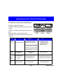
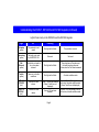
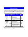
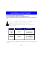
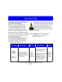
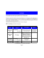
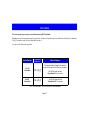
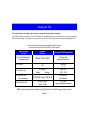
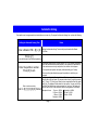
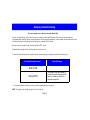
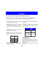
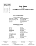
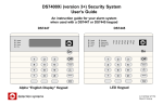
DS7080i Version 2+
Security System User’s
Guide
An instruction guide For your alarm system
when used with a
DS7447, DS7443S or DS7445 keypad
Armed
Status
Ready To Arm
Power
Fire
On
1
2
3
Off
4
5
6
Perimeter
Only
7
8
9
No
Entry
*
0
#
Bypass
System
Reset
System Overview
Congratulations on the installation of your new security system. No other investment can provide such peace of
mind. Welcome to the DS7080i Version 2+ intrusion/fire control system. Since each installation is unique, your’s will contain
some, but not necessarily all of the features mentioned in this guide.
A security system usually consists of:
• A Control Panel: The control panel is the center of your intrusion/fire alarm system. It supports such vital functions as receiving trouble and
alarm signals from detectors, the sounding of bells and/or sirens, and communicating with your alarm monitoring company.
• Command Control Stations (Keypads): The keypad is where you interact with the system. The keypad displays critical information concerning the operation of your alarm system, plus it allows you to initiate commands such as arming and disarming.
• Protected Zones: Your security system may contain protected windows and doors (perimeter zones), plus various internal sensors. Your
control panel separates perimeter zones from interior protection zones. Specific protection devices may include:
• glass breakage sensors: Devices that detect the sound of breaking glass.
• interior motion sensors: Electronic sensors (e.g. passive infrared) that detect movement within an interior zone.
• magnetic contacts: Switches used to detect the opening of doors or windows.
• smoke detectors: Devices that detect products of combustion.
This system includes a telephone line seizure feature. The system may be programmed to communicate with a central monitoring
station to report system events. You will not be able to use your phone while the system is communicating with the central monitoring
station. In the unlikely event that the central station is not able to receive the report, your phone may be unavailable for up to 20
minutes while the panel makes additional communication attempts.
Page 2
Table of Contents
System Overview
2
Understanding the DS7447, DS7443S and DS7445 Keypads 4
Understanding Partitioning
6
Turning ON (arming) your System
7
Turning ON (arming) your System (continued)
8
Quick Arming Your System
9
Turning OFF (disarming) your System / Silencing Alarms
10
Force Arming your System
11
Zone Bypass
12
Chime Mode
13
Access Control
14
Changing the Date
15
Changing the Time
16
Automatic Arming
17
Delaying Automatic Arming
18
Setting Delayed Arming
19
Emergency Procedures
20
Turning OFF (disarming) your System under Duress
21
Fire Reset / Fire Trouble
Fire Safety
Personal Identification Numbers
Removing a PIN
Error Displays
Testing Your System
Event History Readback
Glossary
Quick Reference Guide
System Features Reference Guide
Index
Your system may or may not be monitored by an alarm monitoring service.
If it is not monitored, it is vital to understand the following:
• Alarms sound only at your location.
• When an alarm is sounded, no signals are sent out.
• Duress and other silent alarms are disabled.
• Emergency alarms sound only at your location.
Page 3
23
24
26
26
29
30
33
34
35
36
38
Understanding the DS7447, DS7443S and DS7445 Keypads
This chart will help you understand what each Light/LED represents.
Armed
The DS7447 is an alphanumeric LCD keypad.
The DS7443S is an LED keypad; its LEDs 1-6 represent the first 6 zones of
the system.
The DS7445 is an LED keypad; its LEDs 1-8 represent the 8 zones of the
system.
Both display information on various control panel functions.
A built-in sounder is used to annunciate keystroke entries and as an interior
warning device.
Light
Off
Armed
(red)
The control panel is disarmed.
Ar me d
Status
Sta tus
Power
Power
Fire
1
4
2
5
Ar med
P erim eter
3
6
Sta tus
S upe rvisory
TEST WEEKLY
Fir e
1
2
3
4
5
6
7
8
9
*
0
#
Off
1
2
3
Off
P erim ete r
Onl y
4
5
6
Perimeter
Only
7
8
9
No
Entry
*
0
#
Bypass
No
Entry
B ypa ss
System
R eset
S yste m
Rese t
DS7447
Flashing
1- Alternating On/Off. Exit delay is in
progress or an alarm has occurred.
2- Blinks Off once every 2 seconds. Partition
1 is armed and Partition 2 is not armed.
Po wer
B ell S ilence d
Fir e
Trouble
1 2 3 4 5 6 7 8
On
On
On
DS7443S
1
2
3
4
5
6
7
8
9
*
0
#
Off
Peri me ter
Only
No
Entry
Bypa ss
Syste m
Re set
DS7445
On
The control panel is armed,
(in a partitioned system, both
partitions are armed) and no
alarms have occurred.
3- Blinks Off twice every 2 seconds. Partition
2 is armed and Partition 1 is not armed.
Status
(green)
One or more zones are
not ready to arm.
Power
(green)
The control panel has lost
power. There is no AC or
battery.
Control panel problems exist.
See Error Displays on p. 25.
The control panel is in normal operation.
It is running on AC power with no problems.
Fire
(red)
There are no fire alarms.
A fire zone is in alarm.
A fire trouble condition exists.
One or more zones are
bypassed.
Page 4
All zones are ready to arm.
continued on next page
Understanding the DS7447, DS7443S and DS7445 Keypads (continued)
Lights Present only on the DS7443S and the DS7445 Keypads
Light
Off
Flashing
Perimeter
(yellow)
The perimeter is not
armed.
This Light will not flash.
The perimeter is armed.
Supervisory
(yellow)
This Light is not used
by the DS7080i V2+.
Not used.
Not used.
Bell
Silenced
(yellow)
The bells do not need to
be or have been
silenced.
This Light will not flash.
There has been a Fire alarm and
the bells have been silenced.
To clear, enter the Fire Reset command.
Trouble
(yellow)
There are no trouble
conditions.
This Light will not flash.
A trouble condition exists.
LEDs 1-6
DS7443S
(red)
There are no zone
alarms.
LEDs 1-8
DS7445
(red)
There are no zone
alarms.
A zone (1-8) has been alarmed. A zone (1-8) is Not Ready to Arm or
if a fire zone, a trouble condition exists.
(Zones 7 and 8 are not
(Zones 7 and 8 are not displayed)
displayed)
A zone (1-8) has been
alarmed.
Page 5
A zone (1-8) is Not Ready to Arm or
if a fire zone, a trouble condition exists.
Understanding Partitioning
Your alarm system may be Partitioned.
A Partitioned system is a system that is divided into two areas which may be armed and disarmed independently.
The following applies in a Partitioned system:
• User PIN numbers are always required to perform operations in a Partitioned system.
• DS7447 LCD keypads will alternately display (about every 2 seconds) the current status of each partition.
• DS7443S and DS7445 LED keypads will alternately display (about every 2 seconds) the current status of each partition by way of the LED’s.
See “Understanding the DS7447, DS7443S and DS7445 Keypads” on pages 4 and 5 for details.
• If the User PIN has authority in only one Partition, using that PIN on any keypad will perform Arming and Disarming commands only for the
Partition in which the User has authority.
• If the User PIN has authority in both Partitions, the User may arm or disarm both Partitions by entering the commands from any keypad.
• Only Users with access to both partitions can arm common zones.
• If the User PIN has authority in both Partitions, the User may arm or disarm the first Partition only by entering the PIN number + [##] + the
arming/disarming command. To perform arming or disarming commands in the second Partition only, enter the PIN number + [####] + the
arming/disarming command.
• If Custom Arming (PIN + [#] [4]) is used in a Partitioned system, the following will apply:
- Users with access to both partitions can Custom Arm all zones.
- Users with access to both partitions cannot custom arm a single partition.
- Users with access to Partition 1 can Custom Arm any zones in Partition 1 but cannot arm common zones or zones in Partition 2.
- Users with access to Partition 2 can Custom Arm any zones in Partition 2 but cannot arm common zones or zones in Partition 1.
Page 6
Turning ON (arming) your System
This chart explains the five normal ways to arm the system.
The green Status Light must be on steady and the display* must read “Ready to Arm” in order to arm the system with one of these commands.
Ifthe green Status Lightis noton,orifthe display*is reading “Not Ready, ”then see Force Arming or Zone Bypass for other ways to arm the
system.
If this is a Partitioned system, please read “Understanding Partitioning” on page 6 of this guide before using this chart.
Type of Arming Desired
Command
Sequence***
Normal Arming
No one left on the
premises.
An entry/exit delay
is in effect.
Perimeter Instant
Arming
Someone still on the
premises.
There is NO entry delay
in effect.
PIN + [On]
What will Happen
•
•
•
•
•
•
* = DS7447 only
** = DS7443S & DS7445 only
A single beep will sound.
The red Armed Light will begin to flash.
The green Status Light will turn off.
“Armed” will be displayed.*
“Exit Now” will be displayed during the exit delay interval.*
The red Armed Light will turn on steady after the exit delay
expires.
•
•
•
PIN + [No Entry] + •
[Perimeter Only] •
A single beep will sound.
The red Armed Light will begin to flash.
“Perimeter Inst.” will be displayed.*
“Exit Now” will be displayed during the exit delay interval.*
The red Armed Light will turn on steady after the exit
delay expires.
• The yellow Perimeter Light will turn on steady after the
exit delay expires.**
• Only exterior protection zones will be armed.
What to Do
Exit during the
exit delay
interval.
Move freely
around the
interior.
*** = If in “Residential Mode”, a PIN is not required for these commands.
NOTE: In commercial burglar alarm applications for UL Listed Requirement systems, a ring-back indication and bell test should be heard after
arming (closing). If not heard, call for service.
Page 7
Turning ON (arming) your System (continued)
If this is a Partitioned system, please read “Understanding Partitioning” on page 6 of this guide before using this chart.
Type of Arming Desired
Command
Sequence***
Perimeter Arming
Someone still on the
premises.
PIN +
[Perimeter Only]
The entry/exit delay
is in effect.
Custom Arming
(If programmed)
Ask your installing company
to explain the type of arming
that occurs when using this
command.
Maximum Security
Arming
No one left on the premises.
There is NO entry delay in
effect. An alarm WILL occur
upon entry.
PIN + [#] + [4]
PIN + [No Entry]
+ [On]
* = DS7447 only
** = DS7443S & DS7445 only
What to Do
A single beep will sound.
The red Armed Light will begin to flash.
“Perimeter On” will be displayed.*
“Exit Now” will be displayed during the exit delay interval.*
The red Armed Light will turn on steady after the exit delay
expires.
• The yellow Perimeter Light will turn on steady after the
exit delay expires.**
• Only exterior protection zones will be armed.
Move freely
around the
interior.
What will Happen
•
•
•
•
•
•
•
•
•
•
A single beep will sound.
The red Armed Light will begin to flash.
“On Partial” will be displayed.*
“Exit Now” will be displayed during the exit delay interval.*
The red Armed Light will turn on steady after the exit delay
expires.
• Some zones will be bypassed.
•
•
•
•
•
•
Exit during the
exit delay
interval.
Exit during the
A single beep will sound.
exit delay interval.
The red Armed Light will begin to flash.
The green Status Light will turn off.
CAUTION:
“Armed Instant” will be displayed.*
Violating any zone
“Exit Now” will be displayed during the exit delay interval.* after the exit delay
The red Armed Light will turn on steady after the exit delay
will cause an
expires.
instant alarm.
*** = If in “Residential Mode”, a PIN is not required for these commands.
NOTE: In commercial burglar alarm applications for UL Listed Requirement systems, a ring-back indication and bell test should be heard after
arming (closing). If not heard, call for service.
Page 8
Quick Arming Your System
This chart explains four ways to quick arm the system from the keypads.
If Quick Arming is not used, a PIN must be entered at the beginning of all arming command sequences.
Quick Arming is not available in a partitioned system.
When Quick Arming is used, the following shortcuts are available:
Quick Arming Command Sequence
Type of Arming
[#] + [On]
Normal Arming
[#] + [No Entry] + [Perimeter Only]
Perimeter Arming - no entry delay
[#] + [Perimeter Only]
Perimeter Arming - entry/exit delay
[#] + [No Entry] + [On]
Maximum Security Arming
Page 9
Turning OFF (disarming) your System / Silencing Alarms
This chart explains proper procedures for disarming and/or silencing alarms.
Please read the section about Emergency Procedures prior to being confronted with an emergency event.
If you have entered the building through a perimeter door, you may hear a steady pre-alert tone from the keypads. If so, disarm according to the
chart below.
If the bells and sirens are on and/or the red Armed Light is flashing, then the keypad is signaling that an alarm has occurred
sometime before your arrival. The DS7447 will display “Zone Alarm”. The DS7443S zone LEDs (1-6) (Zones 7 & 8 will not be
displayed) or the DS7445 zone LEDs (1-8) will be flashing for the corresponding zone that is in alarm.
• The keypad will also issue a pulsed tone during the entry delay instead of the usual steady tone.
• If the alarm has not been previously investigated, do not enter the building unless accompanied by the appropriate
Emergency Services’ personnel.
Action Desired
Disarming the
System
Silencing Alarms
Command Sequence
What will Happen *
PIN + [Off]
The red Armed Light will turn off.
Pre-alert sounders will silence.
PIN + [Off]
The red Armed Light will turn off.
Zone LEDs (1-6) on the DS7443S will turn off.
(Zones 7 & 8 are not displayed)
Zone LEDs (1-8) on the DS7445 will turn off.
Alarms in progress will silence.
* In non-partitioned systems. For systems with partitioning, review “Understanding the Keypads” on page 4 and “Understanding Partitioning”
on page 6.
Page 10
Force Arming your System
This chart explains the procedure for Force Arming your
system if one or more zones are faulted.
When one or more zones are faulted, the system may be
Force Armed (if programmed) by bypassing the faulted
zones. The green Status Light will be off on all keypads
when Force Arming is required to arm the system. The
DS7447 display will read “Not Ready” and the DS7443S and
DS7445’s zone LEDs will be on (the DS7443S cannot display
zones 7 & 8) if one of those zones is faulted. In a partitioned
system, only users with authority to the faulted zone may perform the Force Arming of that Partition.
Force Arming during an AC power failure: Regular arming
of the control panel is not permitted during an AC power
failure. Having to Force Arm serves as a warning that the
control panel is operating under backup battery.
Type of Arming
Force
Arming
Enter any
arming sequence.
What will Happen
• A five second beep occurs,
indicating the control panel
has faulted zones and needs
to be Force Armed.
Bypassing or Force Arming removes some of your building’s
protection because it excludes the faulted zones from arming.
Therefore, an intrusion may not be detected or the detection
may be delayed. Always attempt to correct any zone
problems (close doors and windows etc.) before using these
features. If the problem can not be corrected, contact your
installing company.
NOTE: See Zone Bypass for an alternate method of arming
the system when faults exist. Force arming is not
available in UL Listed systems.
What to Do
What will Happen
• The red Armed Light will flash
during the exit delay interval.
Press
[Bypass]
during the 5
second beep.
• The control panel will arm with the
faulted zones bypassed, or a
three-beep error tone occurs
indicating Force Arming has not
been accepted or allowed.
NOTE: If in “Residential Mode”, a PIN is not required for Force Arming.
Page 11
What to Do
Exit during the
exit delay
interval if
leaving.
Zone Bypass
This chart explains the procedure for bypassing a faulted zone prior to arming the system.
There may be occasions when it is desirable or necessary to temporarily bypass one or more zones prior to arming the system. Bypass commands only work when the control panel is disarmed. For instance, an open window may cause the DS7447 display to read “Not Ready” followed
by the zone number. The DS7443S and DS7445 may have one of its zone LEDs on steady (the DS7443S cannot display zones 7 & 8). Only one
zone may be bypassed each time the command is used.
If more than one zone requires bypassing, repeat the command for each zone to be bypassed.
NOTE: See Force Arming for another method of zone bypassing.
Type of Bypassing
Desired
Command
Sequence**
What will Happen
What to Do
Bypass Faulted
Zones
PIN + [Bypass] [X]
(zone number)
The Status Light will begin to flash
if no other zones are violated.
Arm control panel, if
desired, with entered
zone(s) bypassed.
Read Bypassed
Zones
PIN + [Bypass]
“Bypass” will be displayed on the DS7447
followed by the zone number of any
bypassed zones. The DS7443S and
DS7445 will flash the zone LED of any
zone being bypassed (the DS7443S cannot
display zones 7 & 8).
Clear Individual
Bypassed Zone(s)
PIN + [Bypass] [X]
(zone number)
Individual zone bypasses
will be cleared.
Clear All Bypasses
PIN + [Bypass] [*]
All bypasses will be cleared.
** = If in “Residential Mode”, a PIN is not required for these commands.
Page 12
Chime Mode
This chart explains the procedure for turning ON and turning OFF Chime Mode.
Chime Mode causes all the keypad sounders to beep each time a Perimeter or Entry/Exit zone is violated while the control panel is off (disarmed).
The [#] [7] command is used to both turn Chime Mode off and on.
You cannot set the Chime mode by partition.
Action Desired
Command
Sequence*
Turn ON
Chime Mode
PIN + [#] [7]
Turn OFF
Chime Mode
PIN + [#] [7]
What will Happen
The keypad sounders will beep for two seconds
each time a Perimeter or Entry/Exit zone is violated.
The DS7447 display will read
“Chime Mode On” for 5 seconds.
The DS7447 display will read
“Chime Mode Off” for 5 seconds.
* = If in “Residential Mode”, a PIN is not required for these commands.
Page 13
Access Control
This chart explains the procedure for activating devices that require an Access Control PIN.
Your system may or may not use a keypad key sequence to activate other electrical devices.
The special PIN required to perform this function is known as an Access Control PIN.
This feature can be used in armed or disarmed modes.
The PIN may control devices that activate for a short period of time (e.g. electric locking mechanisms on a door).
Momentary Access
Control Panel
Activation
[Access Control PIN] + [Off]
• The Access device will be activated for 10 seconds.
This feature must be disabled on U.L. Listed Requirement installation.
The control panel is not a listed control unit (UL294).
Page 14
Changing the Date
This chart will guide you through the steps necessary to Change the Date displayed at the keypads.
You should write down your entries before you enter the Master Code Programming Mode
and have them with you as you begin programming. Make your entries promptly.
If a long delay occurs in your entries, the 3-beep error tone sounds and exits you from the programming mode.
It is recommended that this procedure be performed at a DS7447 keypad.
No visual cues will be given from the DS7443S or DS7445 keypads.
Steps to Change
the Date
# 1. Enter the Master Code
Programming Mode.
Command
Sequence
If Accepted, DS7447 Display Reads
[Master Code] + [#] [0]
"2 Change Date"
(display will scroll to this)
[2]
“Enter Month"
(01...12)
# 2. Enter a 2.
# 3. Enter the Month.
[0] [1] through [1] [2]
January
December
"Enter Day."
(01...31)
# 4. Enter the Day.
[0] [1] through [3] [1]
"Enter Year."
(XX) End with #
# 5. Enter the Year.
The last two digits of the year,
followed by the [#] key.
“Month, Day, Year”
A long beep signifies acceptance.
NOTE: Entering the command sequence [Master Code] [#] [0] [2] [#] will cause the DS7447 keypad to read back the date.
Page 15
Changing the Time
This chart will guide you through the steps necessary to change the Time displayed at the keypads.
You should write down your entries before you enter the Master Code Programming Mode and have them with you as you begin programming.
Make your entries promptly. If a long delay occurs in your entries, the 3-beep error tone sounds and exits you from the programming mode.
It is recommended that this procedure be performed at a DS7447 keypad.
No visual cues will be given from the DS7443S or DS7445 keypads.
Steps to Change
the Time
# 1. Enter the Master Code
Programming Mode.
Command
Sequence
If Accepted, DS7447 Display Reads
[Master Code] + [#] [0]
"6 Change Time"
(display will scroll to this)
[6]
“Enter Day"
(1...7)
# 2. Enter a 6.
# 3. Enter the Day.
# 4. Enter the Time.
(Hour and minute)
# 5. Enter AM or PM.
[1] through [7]
Sunday
Saturday
[0] [1] [0] [0] through [1] [2] [5] [9]
[4] [#] or [6] [#]
(4=AM, 6=PM)
"Enter Time."
(0100...1259)
"Enter AM/PM.”
(4/6) End with #
“Day - Time”
A long beep signifies acceptance.
NOTE: Entering the command sequence [Master Code] [#] [0] [6] [#] will cause the DS7447 keypad to read back the time.
Page 16
Automatic Arming
Each partition can be programmed to automatically arm once per day. To program the Automatic Arming time , perform the following:
Setting the Automatic Arming Time
Enter a Master PIN + [#] + [0]
Notes
Setting the Automatic Arming Time can only be performed with a Master
PIN Code.
Enter a [1]
to enter the Automatic Arm Setup programming
Enter the partition number.
Press [#] to exit.
Enter a time for each day.
Enter in [0] [1] [0] [0] [#] format.
The program will prompt you to enter partition 1 or 2 if the system is partitioned
and if the user has access to both partitions. If the system is not partitioned or
if the user has access to only one partition, this selection will not appear.
In a non-partitioned system, the display will automatically go to Sunday.
The user will only be allowed to program the partitions to which they are
assigned.
The display will start with Sunday. It will read, “Sunday - nn : nn”
Enter the time in 24 hour format. You may move the cursor left or right by pressing
the "A" (Fire) or "C" (Panic) keys. When you have completed the time entry press
the [#] key. The display will then advance to the next day. You may exit the Set
Auto Arm Time Mode at any time by pressing the * key once. The system will
also exit the Auto Arm Time mode after the time is programmed for Saturday.
12 noon = 1200#
12 midnight = 2400#
Samples of times:
12:01am = 0001#
12:01pm = 1201#
1:00am = 0100#
1:00pm = 1300#
Disabled = 0000#
Page 17
Delaying Automatic Arming
This section explains how to delay the Automatic Arming Time.
To inform occupants that the system is about to arm, a pre-arming period will begin 15 minutes before the system arms automatically.
If programmed by the installing company, the keypad sounders, and any outputs programmed to follow the keypad sounders, will pulse five times
every minute. During the last five minutes before arming, these sounders will be on steady.
Once per minute the keypad will read, “Arm in nn min./PIN + OFF - extend.”
Delayed Automatic arming will affect only the partitions you have access to.
To extend the Automatic Arming of the system during the automatic arming pre-arming period, perform the following steps:
Extending Automatic Arming *
What will Happen
Enter a PIN
The arming time will be extended 30
minutes. A new pre-arming period will
begin 15 minutes prior to the new
automatic arming time.
Press [OFF]
* = To extend the Automatic Arming at any time, use the Delayed Arming feature on page 19.
NOTE: The keypad volume setting also applies to the Auto Arm tone.
Page 18
Setting Delayed Arming
This section explains how to cause the system to arm after a specified number of hours.
Delayed arming is simply causing the system to arm after a specified number of hours.
To program the system for delayed arming, perform the following steps:
Delaying Arming
Notes
Enter a PIN
Enter [#] [9] [9]
to enter the Delayed Arming programming
The keypad will display the following:
Arm in nn Hours
# to accept
Enter the number of hours (up to 23) from now
that you would like the system to arm. If no changes
are required, you may press [*] to exit.
For example: If if is 3:30 now, and you would like
the system to arm at 9:30, enter 06.
Additional Notes: Delayed arming can be used even if there are no automatic arming times programmed.
Setting Delayed Arming will affect only the partitions you have access to. Users with PIN levels of 0-2 will be able to set Delayed arming.
Delayed arming will override automatic arming. Delayed arming will also provide a 15 minute pre-arm period like the
one provided with automatic arming.
You may view the time left (rounded to the nearest hour) to the arming time by entering PIN [#] [9] [9]. The display will show “Arm In __ Hours”.
Pressing the [*] key will exit the display without changing the arming time.
Page 19
Emergency Procedures
Identifying Alarm Sounds
Your alarm system may be programmed for a steady alarm
sound or a pulsed alarm sound. It is important to learn the
difference between a fire alarm sound and an intrusion alarm
sound before you are confronted with an actual emergency.
Silencing Alarms
All alarms can be silenced with any PIN that has disarm
privileges. Entering your PIN + [Off] will silence the alarm
and turn off (disarm) the control.
A Cautionary Note
How you respond to an alarm will depend, mostly, on the
type and time of the alarm. You should seek the advice of
your installing company as they install your system, not later
(e.g. after an alarm) to develop a response plan.
Above all else, common sense should prevail.
If there is any threat or hint of danger to yourself or others on
the premises, such as in the event of a fire alarm, everyone
should be instructed to leave the premises immediately. Do
not enter the premises unless accompanied by the
appropriate Emergency Services’ personnel, or after they
have given the OK to enter.
Caution When Entering A Building
If the bells and sirens are on and/or the red Armed Light is
flashing with the DS7447 display reading “Zone Alarm” or
the DS7445 having its zone LEDs 1-8 flashing, then the
keypad is signaling that an alarm has occurred. The keypad
will also issue a pulsed tone during the entry delay instead of
the usual steady tone.
If the alarm has not been previously investigated, do not
enter the building unless accompanied by the
appropriate Emergency Services’ personnel.
Fire Alarms
Fire Alarms are silenced using the same procedure as
intrusion alarms: a PIN (with disarm privileges) + the [Off]
key.
The Fire Alarm system is not reset until alarms at smoke
detectors are cleared by using the [System Reset] command.
The Fire Alarm system will not be functional until this
procedure has been followed. See Fire Reset on page 23.
Page 20
Turning OFF (disarming) your System under Duress
This chart explains the proper procedure for disarming under Duress.
Ask your installer if the Duress feature has been activated.
A Duress code is used when someone demands, by threatening your life or well-being, that the system be turned off. When used, the code will
both turn off the system and report a silent Duress alarm if connected to a monitoring service. Extreme care should be used when entering your
PIN to turn off the system, so a Duress code is not inadvertently entered. The Duress code will only disarm partitions that it has been assigned
to.
Type of Disarming
Command Sequence
Disarming the
System with the
Duress code
[Duress Code] + [Off]
Page 21
What will Happen
The system will appear to disarm normally.
A Duress report will be sent to your
monitoring service.
Emergency Keypad Alarms / Silencing Alarms
Armed
Status
Armed
1
4
Status
2
5
Power
3
6
Fire
Power
TES T WEEKLY
Fire
On
1
2
3
Off
4
5
6
Perimeter
Only
7
8
9
*
0
#
No
Entry
By pass
B
C
Perimeter
Status
Supervisory
Power
Bell Silenced
Fire
Trouble
1 2 3 4 5 6 7 8
On
On
1
2
3
Off
4
5
6
Perimeter
Only
7
8
9
No
Entry
*
0
#
Bypass
1
2
3
Off
4
5
6
Perimeter
Only
7
8
9
No
Entry
*
0
#
Bypass
System
Reset
Sy stem
Reset
A
Armed
A B C
Sys tem
Res et
A
B
C
The Emergency Alarm Keys [A], [B], and [C] may generate Fire, Special Emergency, and Panic Alarms if programmed by the installer. Ask your
installing company to explain the function of these keys.
When using the Emergency Alarm Keys, they must be pressed for two seconds to generate an alarm.
Note: If the Emergency Alarm Keys are to be used, they should be labeled to signify their functions.
The A key should be labeled as the Fire key. This is the only key that may be designated as the Fire key.
The B key should be labeled as the Special Emergency key.
The C key should be labeled as the Panic key.
Use the Disarming Command Sequence to cancel or silence these alarms.
Page 22
Fire Reset / Fire Trouble
Fire Reset
Fire Trouble
During a fire alarm, exit the premises immediately. When you have determined there is no fire, it is recommended that you silence the bells/
sirens before you initiate the [System Reset] command.
A Fire Trouble display signifies a problem with the fire system, such as
a break in the wiring that monitors smoke detectors.
Before the [System Reset] command is used, determine which smoke detector has alarmed so the installing company may verify its operation.
A PIN followed by the [System Reset] key will reset any
smoke detectors after a fire alarm has occurred.
PIN + [System Reset]
NOTE: To use the System Reset command sequence, your
PIN must have disarm privileges.
A Fire Trouble will be indicated by a short beep from the keypad sounders every 10 seconds. The DS7447 keypad will display “Fire Trouble”
followed by the zones in a trouble condition.
The DS7443S and DS7445 keypads will turn the Fire and Trouble Lights
on steady and will light the corresponding zone LEDs.
Notify your installing company immediately if the Fire Trouble message
is displayed.
The Fire Trouble beep can be silenced with any PIN followed by the
[Off] key. After problems have been remedied, a PIN followed by
[System Reset] should be entered to clear the “Fire Trouble” display.
The System Reset command will perform a fire reset, will
perform a battery test, and will clear all system troubles.
Page 23
Fire Safety
No fire detection system should be considered 100 percent foolproof
This fire alarm system can provide early warning of a developing fire.
Such a system, however, does not ensure protection against property
damage or loss of life resulting from a fire. Any fire alarm system may
fail to warn for any number of reasons (e.g. smoke not reaching a detector
that is behind a closed door).
For added early warning protection, it is recommended that detectors
be installed in all separated areas including the basement, bedrooms,
dining room, utility room, furnace room, and hallways.
When considering detectors for residential applications, refer to NFPA
Standard 72, “The National Fire Alarm Code.” This standard is available
at a nominal cost from: The National Fire Protection Association,
Batterymarch Park, Quincy, MA 02269.
A fire warning may be wasted unless
the family has planned in advance
for a rapid and safe exit from the
building.
If Installed in Family Residences
• Draw a floor plan of the entire
house showing two exits from
each bedroom and two from the
house. Since stairwells and
hallways may be blocked during a
fire, the plan should provide exits
from bedroom windows.
Adherence to the NFPA Standard 72 can lead to reasonable fire safety
when the following items are practiced:
• Minimize hazards: Avoid the three traditional fire killers:
smoking in bed, leaving children home alone, and cleaning
with flammable liquids.
Having and Practicing an Escape Plan
Bedroom
Living
Room
*
Basement
*
Hall
Bedroom
*
*
Dining
Room
= Smoke Detector
A smoke detector should be located on each
story including basements, but excluding crawl
spaces and unfinished attics.
Make copies of the plan and practice it with all family members.
• Providing a fire warning system: Most fire deaths occur in the
home, the majority, during sleeping hours. The minimum level of
protection requires smoke detectors to be installed outside of each
separate sleeping area and on each additional story of the dwelling.
• Prearrange a meeting place outside and away from the residence.
Once out of the building, all occupants should immediately go to the
pre-selected location to be accounted for.
continued on next page
Page 24
Fire Safety (continued)
• Provide a barricade between family members and fire, smoke, and
toxic gases (e.g. close all bedroom doors before retiring).
• Children should be instructed on opening their bedroom windows
and exiting safely from the building. If exiting is not possible, they
should be taught to stay at the open window and shout for help until
it arrives.
• In the event of a fire alarm after retiring, wake the children by shouting
to them from behind your closed door. Tell them to keep their bedroom
doors closed.
• If the top of your bedroom door is uncomfortably hot, do not
open it. There is most likely fire, intolerable heat, or smoke on the
other side. Shout to all family members to keep their bedroom doors
closed and to exit the building via alternate routes.
• If the top of the door is not uncomfortably hot, brace the bottom of
the door with your foot, and the top with one hand, then open the
door about one inch. Be prepared to slam the door shut if there is
any pressure against the door or if any hot air rushes in.
Installation Considerations
Proper location of detection devices is one of the most critical
factors in a fire alarm system.
The following are some general considerations:
• Smoke detectors should not be installed in “dead air” spaces or close
to ventilating or air conditioning outlets because smoke may be circulated away from the detector. Locations
near air inlets should be favored.
Rec Room
Dining
Room
Kitchen
Living Room
**
Bedroom
Bedroom
*
Bedroom
= Smoke Detector
Locate smoke detectors between
sleeping areas and family living
areas.
• Avoid areas subject to normal smoke concentrations such as kitchens,
garages, or near fireplaces.
• Do not install smoke detectors where normal area temperatures are
above 100 degrees F (38 degrees C) or below 32 degrees F (0 degrees
C).
• Areas of high humidity and dust concentrations should be avoided.
• If there is no evidence of excessive heat or pressure, leave the
room and close the door behind you. Shout appropriate
instructions to all family members and immediately leave the building
via the pre-planned routes. If heavy smoke is present, drop to your
hands and knees, or crawl to remain below the smoke level.
• The edge of ceiling mounted detectors should be no closer than 4
inches (10 cm) from any wall.
• Place the top edge of wall mounted detectors between 4 and 12 inches
(10 to 30 cm) from the ceiling.
Page 25
Personal Identification Numbers
General Information
When programing Personal Identification Numbers, it is helpful to know
the following terms:
• PIN: Personal Identification Number. This is the 4 or 6 digit code
users enter at the keypad to gain access to the system. A PIN may
be assigned to each User Number 001 - 015.
• Partition (Area): This is the area the User has authority in. You may
select Partition (Area) 1, 2 or both.
• User Number: This is the number that identifies each person using
the system. There are 15 possible User Numbers (001 - 015).
• Authority Level: This number determines which functions each user
will be able to perform (see page 27).
Your system has the capacity to assign up to 15 PINs. The length of
the PINs will be fixed at 4 or 6 digits. You cannot have both 4 and 6 digit
PINs in the same system. If you wish to change the PIN length, it will
be necessary to have your installing company make the change. If
changed, all new PINs will need to be assigned. Each User number
may have only one PIN assigned to it. Attempting to assign the same
PIN to multiple User Numbers will result in a 3 beep entry error tone,
and the entry will not be made.
User Number 001 is designated as a Master Code. It can be used to
add, delete or change other PINs.
User Number 001 is shipped from the factory with the sequence of
123456. This code should be changed to one of your personal
preference, and must be programmed as a Master Code. PINs should
never be programmed with common sequences such as 1111 or 2468
because they are easily violated.
Removing a PIN
To remove a PIN: enter a [Master Code] [#] [0] [0], the User Number of
the PIN to be canceled, and then [#] again.
Page 26
User Number 001 can not be canceled in this manner.
continued on next page
Personal Identification Numbers (continued)
PIN Authority Levels
0 = Master: Can enter all commands, add or change PINs, change
time and date, bypass, arm, set autoarm, disarm, perform system
tests, system reset, and view history. PIN 001 must be a master
code and must have authority 0. Any or all PINs may be master
codes.
4 = Temporary: Valid only for a limited time. Can arm and disarm the
system, but can not perform any other functions. This code will
automatically be deleted after 15 days if you have not already done
so.
The 15 day clock is reset to 15 days each time a Temporary
PIN is assigned. All Temporary PINs expire at the same
time.
1 = Unlimited: Can enter all commands, bypass, arm, disarm, system
reset, and perform system tests. Can not change PINs.
2 = General: Can bypass, arm and disarm. Can not change PINs,
system reset, or enter the [#] [7] or [#] [8] functions.
3 = Arm Only: Can arm the system with [#] [On] arming only. Can not
perform any other functions including disarming.
5 = Duress: When the system is disarmed using a duress code, a
silent report is sent to the central station. Duress codes are intended
to be used when the user is forced to disarm the system.
6 = Access: When a PIN with Access Code authority is entered, any
output programmed for Access Output (e.g. door strikes) will pulse
on for 10 seconds (works when the system is armed or disarmed).
Page 27
continued on next page
Personal Identification Numbers (continued)
This chart will guide you through the steps necessary to change a PIN.
You should write down your entries before you enter the Master Code Programming Mode and have them with you as you begin programming.
Make your entries promptly. If a long delay occurs in your entries, the 3-beep error tone occurs and exits you from the programming mode.
Steps to Change a
PIN
# 1. Enter the Master Code
Programming Mode.
# 2. Enter a 0.
# 3. Enter the User Number.
# 4. Enter the Authority Level.
# 5. Enter the PIN.
# 6. Enter the PIN again followed by
the [#] key.
Command
Sequence
If Accepted, DS7447 Display Reads
[Master Code] + [#] [0]
“0 User Change”
(display will scroll to this)
[0]
“Enter User No.”
(001..0XX)
[0] [0] [1] through [0] [1] [5]
“Enter Authority Level”
Level (0-6)
[0] through [6]
“Enter PIN”
Any 4 digits.
Do not press [#].
“Enter PIN Again. End with #”
PIN (same 4 digits as above),
then [#].
A long beep will sound to signify
acceptance of the new PIN.
Page 28
Error Displays
This chart explains the procedure for reading Error messages when the green Power Light is flashing.
Control panel problems are indicated by a flashing green Power Light and the DS7447 display reading “Control Trouble, Enter #87.”
Error messages may only be read when the control is disarmed. Contact your installing company if the problems persist.
1. “AC Power Failure”* or LED #1 on steady**: There is a power failure
and the control panel is running on backup battery.
6. “Aux Power Fault”* or LED #8 on steady**: The Auxiliary power has
been shorted.
2. “Battery Trouble”* or LED #2 on steady**: If the system has just
been through a power failure, wait at least two hours for the battery
to recharge, then enter a PIN + [System Reset] to perform a battery
test.
7. “Zone Trouble”* or LED #6 on steady**: One or more of the zones is
not responding to the control panel. This may also display during
power-up (if so, ignore).
3. “Communicator Err”* or LED #3 on steady**: The communicator
failed to communicate with the central station.
4. “System Fault”* or LED #4 on steady**: Internal error in the control
panel’s circuitry or optional circuitry. These faults are designated as
follows:
[#] [8] [7]
will display
[#] [8] [9]
will display
RAM Fault
ROM Fault
EEPROM Fault
TRBL Zone Fault
System Fault 01
System Fault 02
System Fault 03
System Fault 05
5. “Keypad Fault”* or LED #5 on steady**: One of the keypads is not
responding to the control panel.
Action Desired
Command
Sequence***
Read the Error Display when the
green Power Light is flashing
PIN + [#] [8] [7]
Clear the Error Display****
Caution: Clear the error display
only on the advice of your installing
company or if you are certain the
problem has been remedied.
PIN + [System Reset]
* = the DS7447 display
** = the DS7443S and DS7445 displays
*** = If in “Residential Mode”, a PIN is not required for these commands.
**** = Battery Trouble and Communicator Err displays must be cleared by the
[System Reset] command sequence even after the problem has been remedied.
These displays will not self clear.
All the other error displays will self clear from the keypads once the problem has
been remedied.
Page 29
Testing Your System
This chart explains the procedure for performing a Zone Test.
It is recommended that the system be tested weekly.
The Zone Test is used to confirm that detectors will report alarms to the keypad.
A Zone Test works on all zones, except 24-hour zones and fire zones.
While the keypad is in a Zone Test, no control panel alarms will activate an alarm, except 24-hour zone alarms and fire alarms; these will override
the Zone Test function.
Type of
Test
Zone Test
Command
Sequence*
PIN + [#] [8] [1]
What will Happen
What to Do
“Test Zone” will display on the DS7447 followed by
the zone number of any zones that have not been
tested.
The DS7443S and DS7445 keypads will flash the zone
LEDs of any untested zones. The DS7443S cannot
display zones 7 & 8.
Test each detector one at a
time as instructed by the
installing company.
“Now Testing” will display on the DS7447 followed by
the zone number of the zone that is currently being
violated (tested). It returns to “Test Zone” after the
violation.
The DS7443S and DS7445 will turn the zone LED on
steady for the zone that is currently being violated (tested).
The DS7443S cannot display zones 7 & 8.
* = If in “Residential Mode”, a PIN is not required for this command.
Page 30
To exit the Zone Test mode,
enter your PIN followed by
the [#] key.
Testing Your System (continued)
This chart explains the procedure for performing a Battery Test.
If a power failure occurs, your control panel has a built-in battery that will continue to power the control panel for many hours. The control panel
automatically recharges the battery when power is restored.
In addition to an automatic battery test performed every 2 minutes, the battery may also be tested manually.
This test also uses the battery to manually activate all the system sounders for 2 seconds (# 8 5 only). If the battery voltage is low, a battery fault
will occur (see Error Displays).
Type of Test
Local
Battery/
Sounder Test
Battery
Test
Command
Sequence*
What will Happen
• All keypad Lights will turn on.
PIN + [#] [8] [5]
• The keypad sounder and all alarm
sounding devices will operate for 2
seconds.
What to Do
If test fails, the control panel will
indicate a control problem. See
Error Displays.
If power in your building has been
off recently, wait 2 hours for the
battery to recharge and then try
again.
• The control panel will perform a
Battery Test.
PIN + [System Reset]
• The control panel will report a Low
Battery or a Low Battery Restoral if
necessary.
* = If in “Residential Mode”, a PIN is not required for these commands.
Page 31
Testing Your System (continued)
This chart explains the procedure for performing a Communicator Test.
This test is available only if your system transmits alarms and system information to a monitoring service, and has been programmed by the
security installing company to permit communicator tests.
A long beep will initially sound to acknowledge the start of the test.
If the test is successful, the sounder will again issue one long beep.
If the test fails, the keypad sounder will turn ON continuously. To silence the sounder, enter you PIN followed by the [#] key or press the [*] key.
Type of Test
Communicator
Test
Command
Sequence**
PIN + [#] [8] [2]
What will Happen
• A long beep will sound.
• A "Test" report is sent to the monitoring
service.
What to Do
If test fails, the keypad sounder
will sound continuously. To
silence the sounder, enter your
PIN followed by the [#] key or the
[*] key.
Note: This test may take several
minutes to complete because the
control panel will try 10 attempts
before it fails this test.
** = If in “Residential Mode”, a PIN is not required for this command.
Page 32
Event History Readback
This chart explains the procedure for performing an Event History Readback.
The History Buffer stores the last 100 events in memory. The most recent 10 events are stored in non-volitile memory and
will be retained even in the event of a power loss. The DS7447 can display all of these events.
The DS7443S and DS7445 keypads will only display those zones that have alarmed. The DS7443S cannot display zones 7 & 8.
Type of Test
Event History
Readback
Command
Sequence**
PIN + [#] [8] [9]
What will Happen
What to Do
The last event to take place will be displayed
on the DS7447 keypad.
For the DS7443S and DS7445 keypads, the zone
LEDs will flash for any zones that have alarmed.
The DS7443S keypads cannot display
zones 7 & 8.
For the DS7447 keypad, scroll
through the events by using the
[9], [6], and [#] keys. See below.
To exit from the Event History
Mode, press the [*] key.
** = If in “Residential Mode”, a PIN is not required for this command.
DS7447 Only: Scrolling through the History Events.
To begin scrolling back through the events, press the [#] key. The [#] key will scroll you back through the history line by line. The [9] key will scroll
you back in reverse chronological order by event. A [6] will scroll you back up through the events (toward the most recent) by event.
Each event consists of two lines or display screens. The first line/screen will be the event title and user. The second line/screen will be the date of
the event or the change being made.
To exit the Event History Mode, press the [*] key or wait 20 seconds and the keypad will exit automatically.
Page 33
Glossary
Access Control PIN
An Access Control PIN is a special code used
to activate electric door locks or other
mechanisms connected to the control panel
that
require this code to turn them on or off.
Armed/Disarmed
Arming the system (burglar zones) means to
turn it on. Disarming the system means to turn
it off. Remember, fire protection (if installed) is
always Armed/on.
Central Station/Monitoring Service
A Central Station/Monitoring Service is a facility
used to continuously monitor phone signals
from your system. Trained personnel there
dispatch proper authorities as necessary.
Custom Arming
Custom Arming is a type of arming that uses
the [#] [4] sequence. It is only a valid sequence
if programmed by the installing company. It is
a specific type of arming designed for your
individual installation needs. Ask your installing
company to explain Custom Arming further.
Disarming Command Sequence
The Disarming Command Sequence is the
sequence of keys you press at the keypad to
disarm the system and/or silence alarms. It
consists of your PIN followed by the command
[Off] button.
Entry Delay
An Entry Delay is a predetermined amount of
time that allows entry into an armed area.
Exit Delay
An Exit Delay is a predetermined amount of
time that allows you to exit an area just after
you have armed it.
Faulted Zone
A Faulted Zone is a zone that is not ready to
arm (e.g. an open door or window). It may also
be described as being violated.
Force Arming
Force Arming is a way of arming the system
by bypassing zones that are not ready to arm.
This reduces the level of security and should
be avoided.
Installing Company
The Installing Company is the company that
physically installed the system. It may or may
not be the same company who monitors the
system.
Page 34
Local System
A Local System is a system that has a control
panel that is not programmed to call a
monitoring service. It will sound only local (on
sight) bells or sirens when an intrusion or fire
alarm
is detected.
Monitored System
A Monitored System is a system that uses
phone lines to notify a monitoring service of
programmed abnormal events such as burglar
or fire alarms.
Zone
A Zone is an input to the control panel. There
are eight hard-wired zones on the control panel.
A zone is usually some type of detection device
whether it be designed for burglar or
fire.
Zone Bypassing
Zone Bypassing is a way of arming the system
by deliberately eliminating zones to be armed.
Zone Function
A Zone Function is the description of how a
zone behaves in the system. Zone Functions
usually define how a zone will respond when
armed or when it detects an alarm.
Quick Reference Guide
This system should be tested weekly to ensure it is functioning properly. If problems are detected in testing or changes are noticed in normal
operation, call your installing company for service. The manufacturer recommends replacing the system battery every 3 to 5 years.
Monitoring Service Phone Number. ______________________________
Monitoring Service System Number. _____________________________
Installing Company Phone Number: _____________________________
Protection
Zone 1 _______________________
Zone 2 _______________________
Zone 3 _______________________
Zone 4 _______________________
Zone 5 _______________________
Zone 6 _______________________
Zone 7 _______________________
Zone 8 _______________________
Page 35
System Features Reference Guide
Perimeter Arming, with entry delay:
[PIN] + [Perimeter Only]
Audible Alarm Signaling Device Sounds
Intrusion ( ) Pulse ( ) Continuous
Fire
( ) Pulse ( ) Continuous
Maximum Security Arming:
[PIN] + [No Entry] + [On]
Keypad Supplemental Alarm [B] Key
( ) Continuous ( ) Silent
This system has the Duress Alarm feature. ( ) Yes
( ) No
This system has the communicator test feature. ( ) Yes
This system is partitioned. ( ) Yes
12345678-
Partition 1 Zones
_____________
_____________
_____________
_____________
_____________
_____________
_____________
_____________
( ) No
Partition 2 Zones
______________
______________
______________
______________
______________
______________
______________
______________
Turning On (arming) Your System
Normal Arming:
[PIN] + [On]
Perimeter Arming, no entry delay:
[PIN] + [No Entry] + [Perimeter Only]
( ) No
Common Zones
_____________
_____________
_____________
_____________
_____________
_____________
_____________
_____________
Custom Arming
PIN + [#] + [4] Arms __________________________________
Force Arming
Enter an arming command sequence followed by the [Bypass] key. The
maximum number of zones that can be forced armed is _____
Zone Bypass
[PIN] + [Bypass] followed by the Zone number.
Quick Arming Your System
Normal Arming: [#] + [On]
Perimeter Arming, no entry delay:
[#] + [No Entry] + [Perimeter Only]
Perimeter Arming, with entry delay:
[#] + [Perimeter Only]
Maximum Security Arming:
[#] + [No Entry] + [On]
Turning Off (disarming) Your System
Enter your [PIN] followed by [Off]
Page 36
System Features Reference Guide (continued)
Chime Mode
PIN + [#] [7]
Error Display
PIN + [#] [8] [7]
Zone Test
PIN + [#] [8] [1]
Error Display Reset
PIN + [System Reset]
Read Event History
PIN + [#] [8] [9]
Clear Zone Bypass
PIN + [Bypass] [*] to clear
Battery Test
PIN + [System Reset]
Access Control
PIN + [Off]
Communicator Test
PIN + [#] [8] [2]
Set Delayed Arming
PIN + [#] [99]
Fire Reset
PIN + [System Reset]
Delay Auto Arm by 30 Minutes
PIN + [OFF]
Fire Trouble
PIN + [Off] to silence, PIN + [System Reset] to clear
Select Partition 1 only
PIN + [#] [#]
Remote Program Dial-out
PIN + [#] [8] [3]
Select Partition 2 only
PIN + [#] [#] [#] [#]
Remote Program Answer
PIN + [#] [8] [6]
Local Battery/Sounder Test
PIN + [#] [8] [5]
Page 37
Index
A
AC Power Failure 29
AC power failure 11
Access Control 14
Access Control PIN 34
Access PIN 27
Arm Only PIN 27
Armed 34
Authority Level 26
Automatic Arming 17
Aux Power Fault 29
B
Battery Test 31
Battery Trouble 29
bypass 12
C
Central Station 34
change a PIN 28
Change the Date 15
change the time 16
Chime Mode 13
Communicator Err 29
Communicator Test 32
Control Panel 2
Control Station 2
Control Trouble 29
Custom Arming 6, 34
D
Date 15
delay auto arm 18
Delayed Arming 19
Delayed Automatic Arming 18
Disarmed 34
disarming 10
Disarming Command Sequence 34
DS7445 4
DS7447 4
Duress 21
Duress PIN 27
E
Entry Delay 34
Event History 33
Exit Delay 34
L
T
line seizure 2
Local System 34
Temporary PIN 27
Time 16
M
U
Master PIN 27
Monitored System 34
Monitoring Service 34
Unlimited PIN 27
User Number 26
N
Zone 34
Zone Bypassing 34
Zone Function 34
Zone Test 30
Zone Trouble 29
Not Ready 7
P
Faulted Zone 34
Fire Alarms 20
Fire key 22
Fire Reset 23
Fire Safety 24
Fire Trouble 23
Force Arming 11, 34
Panic key 22
Partition 26
Partitioned 6
Personal Identification Numbers 26
PIN 26
PIN Authority Levels 27
PIN Master 27
Protected Zones 2
G
Q
F
General PIN 27
quick arm 9
H
R
History Buffer 33
History Readback 33
Ready to Arm 7
S
I
Setting Delayed Arming 19
Silencing Alarms 20
Special Emergency key 22
System Fault 29
Installing Company 34
K
Keypad Fault 29
Page 38
Z
Notes
Page 39
Detection Systems, Inc., 130 Perinton Parkway,
Fairport, New York, USA 14450-9199
(585) 223-4060 • (888) 289-0096 • Fax: (585) 223-9180
Copyright © 2001 Detection Systems, Inc.
DS7080i Version 2+ Users Guide
P/N: 34858C
9/01
Page 40