1
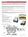
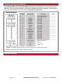
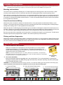
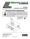
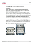
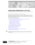
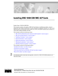
GENERIC
Installation / Configuration Manual
T300 Transmitter
R160 Receiver
D160 Expansion Module
Revised February 9, 2007
Version 5
DMAN - xxxx - xx
#74-1833 Coast Meridian Road, Port Coquitlam, BC, Canada • V3C 6G5
Ph# (604) 944-9247 • Fax# (604) 944-9267
Toll Free 1-800-663-8806
DMAN-xxxx-xx
www.omnexcontrols.com
1
call toll free: 1-800-663-8806
Table of Contents
System Overview .........................................................................................................................................................3
Features........................................................................................................................................................................3
T300 Dimensions and Controls ....................................................................................................................................3
Installing the Receiver ..................................................................................................................................................4
Receiver Dimensions ....................................................................................................................................................4
Installing the Expansion Module ...................................................................................................................................5
Installation Considerations............................................................................................................................................6
Power the Transmitter ..................................................................................................................................................6
Test the Transmitter / Receiver Link.............................................................................................................................7
Download ID Code........................................................................................................................................................7
Calibrating Proportional Controls..................................................................................................................................9
Diagnostics—T300 Transmitter ....................................................................................................................................10
Diagnostics—D160 Expansion Module ........................................................................................................................10
Diagnostics—R160 Receiver........................................................................................................................................11
Troubleshooting Guide .................................................................................................................................................12
Parts & Accessories......................................................................................................................................................16
Specifications................................................................................................................................................................16
Warranty Information ....................................................................................................................................................16
NOTE: These instructions are intended only for installing and operating the remote control equipment described here. This is not a
complete Operator’s Manual. For complete operating instructions, please read the Operator’s Manual appropriate for your particular
machine.
Safety Precautions
READ ALL INSTRUCTIONS
CAUTION: Changes or modifications not expressly approved by the party responsible for compliance could void the
user's authority to operate the equipment.
Failure to follow the SAFETY PRECAUTIONS may result in radio equipment failure and serious personal injury
Installation
PROVIDE A SAFETY CUTOFF SWITCH. If maintenance is required, the radio must be disconnected from power
USE PROPER WIRING. Loose or frayed wires can cause system failure, intermittent operation, machine damage, etc.
DO NOT INSTALL IN HOT AREAS. This apparatus can be damaged by heat in excess of 158° F (70° C)
Personal Safety
MAKE SURE MACHINERY AND SURROUNDING AREA IS CLEAR BEFORE OPERATING. Do not activate the remote
system unless it is safe to do so.
TURN OFF THE RECEIVER POWER BEFORE WORKING ON MACHINERY. Always disconnect the remote system
before doing any maintenance to prevent accidental operation of the machine
Care
KEEP DRY. Do not clean the transmitter / receiver under high pressure. If water or other liquids get inside the transmitter battery or receiver compartment, immediately dry the unit. Remove the case and let the unit air dry
CLEAN THE UNIT AFTER OPERATION. Remove any mud, dirt, concrete, etc. from the unit to prevent clogging of buttons, switches, etc. by using a damp cloth.
Maintenance / Welding
DISCONNECT THE RADIO RECEIVER BEFORE WELDING on the machine the receiver is connected to. Failure to disconnect will result in the destruction of the radio receiver.
call toll free: 1-800-663-8806
DMAN-xxxx-xx
www.omnexcontrols.com
2
System Overview
The ORIGA T300 / R160 / D160 is a portable, long range, programmable radio remote control system. Designed as
a compact and easy-to-use product, this member of the ORIGA family puts complete control of your crane where it’s
needed most, with the operator. It’s robust, easy to install and has complete self-diagnostics. This system can be a
simple cable replacement or add intelligence to make it a total control package. It’s a radio, a PLC and a valve driver
all in one.
The ORIGA T300 / R160 / D160 system uses Frequency Hopping Spread Spectrum (FHSS) technology. FHSS devices concentrate their full power into a very narrow signal that randomly hops from frequency to frequency within a
designated band. This transmission pattern, along with CRC-16 error-checking techniques, enables signals to overcome interference that commonly affects licensed radios.
The R160 receiver is designed to be powered from a 12VDC or 24VDC system. It features 19 solid state, high-side
driver input / output controls and a reliable E-Stop control.
The D160 Expansion Unit has up to 19 input/output (including 2 proportional) combinations, PWM, or voltage outputs,
or a combination of these types.
The T300 transmitter comes with up to sixteen proportional and sixteen digital controls. The T300 can accommodate up to eight single axis paddles, eight three-position switches and a re-settable E-Stop. A unique ID code is used
by each T300 to ensure that no two systems will conflict on a job site.
T300 Transmitter
Features
•
•
•
•
•
•
•
•
FCC, ISC, CE approved
License free
1200 foot range @ 900 MHz (900 ft @ 2.4 GHz)
Compact / weatherproof / ergonomic
Simple “wire-and-use” installation
Resilient to impact and shock
Available in both 900 MHz and 2.4 GHz
Available with paddles and/or joysticks for proportional control
• Available with an optional pendant cable
• Factory configurable for all custom applications.
R160 Receiver
T300 Dimensions and Controls
Power / calibration switch
Switches 2 - 8
D160 Module
Pendant con-
E-Stop
STOP
6.0”
Battery/
Pendant LED
Active LED
E-Stop LED
Paddles 1 - 8
9.5”
DMAN-xxxx-xx
www.omnexcontrols.com
3
call toll free: 1-800-663-8806
Installing the Receiver
Use the Wiring Diagram and the Connector Diagram below to connect the receiver pins directly to the appropriate
contacts of the machine electronics. R160 Output Cables can be provided with every system to simplify the wiring process. The Wire Color column below only applies to the OMNEX Output Cable configuration. Tips on mounting, power
connections and filtering are also provided under Installation Considerations.
Wiring Diagram
Pin-Output
Wire Colors
B7
B8
Notes
Functions
Factory Configurable Only
Factory Configurable Only
________________
________________
B12
B11
B10
A1
-
19
18
17
16
Black/Red
White/Black
Blue/White
Blue/Black
Input / Output
Input / Output
Input / Output
Input / Output
________________
________________
________________
________________
A2
A4
- 15
- 14
Black/White
Green/Black
Input / Output
Input / Output
________________
________________
B9
B6
B5
B4
B3
B2
B1
A12
A10
A11
A9
A8
A7
-
Red/White
Orange
White
Green/Black/White
Green
Red/Black/White
White/Red/Black
Orange/Red
Orange/Black
Blue/Red
White/Red
Red/Green
Orange/Green
Input / Output
Input / Output
Input / Output
Input / Output
________________
________________
________________
________________
________________
________________
________________
________________
________________
________________
________________
________________
________________
13
12
11
10
9
8
7
6
5
4
3
2
1
A5
Black/White/Red
A6
Red
A3
Black
Input / Output
Input / Output
Input / Output
Input / Output
Input / Output
Input / Output*
Input / Output*
Input / Output**
Input / Output**
Switches to Power with
Link
Note: Enable output:
On when the T300
"Enable" switch is on.
Power Input
(+9V to 30VDC)
Ground
Outputs: 19 solid state, high-side driver outputs, 5A max. per pin and 7A max per bank, total combined current 15A
Inputs: All output pins can be factory configured as inputs. Input pins should be connected to a current limiting (fused) source
Connector Pin Assignments
R160 / D160 Dimensions
Connectors as seen from under the receiver
ES
FA
L
STA
5.13”
A
B
4.00”
DMAN-xxxx-xx
www.omnexcontrols.com
4
call toll free: 1-800-663-8806
Installing the Expansion Module
Use the Wiring Diagram and the Connector Diagram below to connect the Expansion module pins directly to the appropriate contacts of the machine electronics. D160 Output Cables are provided with every system to simplify the wiring process. The Wire Color column below only applies to the OMNEX Output Cable configuration. Tips on mounting,
power connections and filtering are also provided under Installation Considerations.
Wiring Diagram
Pin-Output
D160 Module
Internal Wiring
Wire Colors
B7
B8
Functions
Notes
Factory Configurable Only
Factory Configurable Only
________________
________________
B12
B11
B10
A1
-
19
18
17
16
Black/Red
White/Black
Blue/White
Blue/Black
Input / Output
Input / Output
Input / Output
Input / Output
________________
________________
________________
________________
A2
A4
- 15
- 14
Black/White
Green/Black
Input / Output
Input / Output
________________
________________
B9
B6
B5
B4
B3
B2
B1
A12
A10
A11
A9
A8
A7
-
Red/White
Orange
White
Green/Black/White
Green
Red/Black/White
White/Red/Black
Orange/Red
Orange/Black
Blue/Red
White/Red
Red/Green
Orange/Green
Input / Output
Input / Output
Input / Output
Input / Output
________________
________________
________________
________________
________________
________________
________________
________________
________________
________________
________________
________________
________________
13
12
11
10
9
8
7
6
5
4
3
2
1
A5
Black/White/Red
A6
Red
A3
Black
Input / Output
Input / Output
Input / Output
Input / Output
Input / Output
Input / Output
Input / Output
Input / Output
Input / Output
Switches to Power with
Link
Power Input
(+9V to 30VDC)
Ground
Outputs: 19 solid state, high-side driver outputs, 5A max. each, total combined current 15A
Inputs: All output pins can be factory configured as inputs.
Special Functions
DMAN-xxxx-xx
www.omnexcontrols.com
5
call toll free: 1-800-663-8806
Installation Considerations
NOTE: The FCC and ISC require that the antenna be restricted to that supplied by the manufacturer and approved for use with this product. An optional 0dB coax wire antenna may be supplied. For other antenna options, please contact OMNEX Control Systems ULC
Mounting and Installation
The receiver can be mounted by fastening two ¼” bolts through the two mounting holes in the unit’s enclosure. When
mounting, ensure that the receiver is oriented so that the text is reading right and the connectors pointing “down”.
When selecting a mounting point for the receiver, it is recommended that the location require only a minimal length of wiring to connect it to the control panel, that it will be in a visible area where it has good exposure to the operator and that it
is mounted on a surface that sustains minimal vibration. It is also recommended that the receiver have the best possible
line of sight with the transmitter
Power Connections and Wiring
Whenever a power connection is made to an electronic device, it is a good practice to make both the Power (+) and
Ground (-) connections directly to the Battery and avoid connecting the power from the charging side of existing wiring or
making use of existing "ACC" or other peripheral connection points.
Make sure that wire of sufficient gauge and insulator type is used when connecting the outputs of the receiver to the control panel. Observe any component manufacturer's instructions and recommendations for proper integration of their product. This includes the power ratings and requirements of such components as relays, valves, solenoids, etc.
Be sure to test each of the outputs with a multi-meter prior to connecting the outputs to your end devices. This will ensure
that each output has been programmed to operate in the manner required by each end device.
Filtering and Noise Suppression
Whenever a solenoid or electromagnetic switch is controlled by the receiver, it is a good practice to install a Diode across
its terminals to ensure that surges and spikes do not continue back into the circuit. Appropriate 36V Bi-directional Diodes
kits can be ordered under the OMNEX part number “AKIT-2492-01”.
Power the Transmitter
1. Install the batteries in the transmitter
Batteries are installed in the transmitter by removing the battery cover using a slotted
screwdriver and inserting 4 “C” alkaline batteries. Orientation of the batteries is embossed inside the battery housing. No batteries are required when the transmitter is connected to the receiver by a Pendant cable.
NOTE: For operation at temperatures below –10° C lithium batteries are recommended. Low temperatures
reduce battery performance for both alkaline and lithium types. Refer to the battery manufacturer’s specifications
for detailed information on low temperature performance.
2. Turn on the transmitter
Transmitter Battery
Housing
Ensure all transmitter switches and paddles are in the neutral position. Turn on the transmitter by, pressing and
releasing the [Power] switch The RED (E-Stop) light will flash quickly. Release the [E-Stop], the yellow (Active) light
on the transmitter will begin to flash.
WARNING: do not install batteries backwards, charge, put in fire, or mix with other battery types. May explode or leak causing injury.
Replace all batteries at the same time as a complete set and do not mix and match battery types.
A. Press the [E Stop]
Light Legend
Solid
DMAN-xxxx-xx
B. Press and release [Power] switch
Slow
Flash
Fast
Flash
Red
Light
Green
Light
www.omnexcontrols.com
6
C. Turn CW & Release [E-Stop]
Yellow
Light
Alternating Red
& Green Light
call toll free: 1-800-663-8806
Test the Transmitter / Receiver Link
Follow these steps to ensure that there is a Radio Link between the transmitter and receiver
Refer to the Light Legend below for diagram details
1. Press [E-Stop]
2. Power the R160
ESTOP
FAULT LINK STATUS
The (E Stop) light and the (Link)
light will come on RED (provided the
transmitter is off), and the (Status)
light will come on GREEN.
3. Power the T300
ESTOP
FAULT LINK STATUS
If the (Active) light on the transmitter is flashing and the (Link) light
on the receiver is flashing GREEN,
a link between the two exists.
NOTE: The transmitter will shut itself off (and the receiver will then shut off all outputs) after 4 hours of inactivity as a battery saving feature. To restart
the timer before the transmitter shuts off automatically, momentarily operate any toggle switch or paddle.
The ORIGA System is now ready for use.
If the receiver's (Link) light does not become GREEN follow the steps under Download ID Code first then Refer
to Troubleshooting guide for more information.
Download ID Code (Use in case of Link Test failure)
Follow these steps to download the transmitter’s unique ID Code into the receiver. This will allow the receiver to establish
a Radio link with a specific transmitter. Refer to Troubleshooting Chart #4 for Tips and Considerations
NOTE: It is necessary to download the ID code when replacing either the transmitter or the receiver.
NOTE: If the transmitter is connected to the receiver with a Tether Cable, completing only steps 4 and 6 is necessary (it is not
necessary to open the R160 case and press the Setup button).
1. Opening the R160 Case
The cap is held on by two plastic tabs at
opposing sides, which can be unlatched as
shown using a screwdriver. Once the cap
is free, the R160 can slide open.
Use a small slotted screwdriver to press the
Side Tabs inward.
ESTOP
FAULT LINK STATUS
NOTE: When replacing the receiver cover, ensure the cover snaps completely into place to create a weather proof seal around the
base of the receiver.
2. Prepare T300
B.
A.
A. Press [E-Stop]
B. Twist CW & release [E-Stop]
Light Legend
Solid
DMAN-xxxx-xx
Slow
Flash
Fast
Flash
Red
Light
Green
Light
www.omnexcontrols.com
7
Yellow
Light
Alternating Red
& Green Light
call toll free: 1-800-663-8806
Download ID Code (Use in case of Link Test failure)
3. Power R160
A.
A. Supply power to the receiver. The (E-Stop) light
and the (Link) light will
come on RED and the
(Status) light will come on
GREEN
ESTOP
NOTE: For this document, orientation
of the paddle and switch operation will
be defined as follows:
Paddle UP—is towards the switches
Paddle DOWN—is away from switches
Switch UP—is away from paddles
Switch DOWN—is towards the paddles.
FAULT LINK STATUS
UP
DOWN
4. Power T300 into Configuration Mode
A.
B.
C.
D.
A. Hold [Power] switch UP
B. Press [E-Stop]
C. Twist CW & release [E-Stop]
0
D. Release [Power] Switch
5. Put R160 into Setup Mode
A. Press & hold [Setup] button
until (Status) light goes from
slow flash to fast flash
B. Release [Setup] button.
(Status) light goes to solid
GREEN, (Link) light turns off
A.
B.
Setup
Button
ESTOP
FAULT LINK STATUS
Setup
Button
ESTOP
FAULT LINK STATUS
NOTE: If left idle in Setup Mode for over 30 seconds, the receiver will time out. The (Link) light and (Status) light will flash RED rapidly. To return to Setup Mode, repeat step 5.
6. Download ID Code
NOTE: When downloading a new ID to a receiver, a safety feature requires that the transmitter be in close proximity to the receiver. This will prevent a transmitter from accidentally reprogramming a different receiver in the area.
A. Press [Power] switch UP
and release
B.
A.
ESTOP
FAULT LINK STATUS
B. (Link) light goes to GREEN.
Once complete, (Link) light
goes to RED as the trans-
Light Legend
Solid
DMAN-xxxx-xx
Slow
Flash
Fast
Flash
Red
Light
Green
Light
www.omnexcontrols.com
8
Yellow
Light
Alternating Red
& Green Light
call toll free: 1-800-663-8806
Calibrating Proportional Controls
The transmitter’s Paddles control the receiver’s proportional output. The Paddles/Joysticks are used in conjunction with
any of the transmitter’s switches. The proportional output can be activated when a switch is held UP or DOWN; it will become active at an increasingly high level as the Paddle/Joystick is pushed/pulled. The minimum and maximum levels of
the proportional output can be calibrated by following these steps.
Refer to the Light Legend below for diagram details.
NOTE: Calibration settings can be reset to factory default in steps 3 & 4 by holding the [Power] switch UP or DOWN for 5 seconds.
1. Power T300, Power R160
A.
B.
A. Refer to steps in “Power the
Transmitter”
ESTOP
FAULT LINK STATUS
B. Supply power to the R160
2. Setup T300 into Configuration Mode
A. Hold [Power] switch DOWN
for 5 seconds until the
(Battery) LED goes to alternating RED and YELLOW.
A.
B.
A.
B.
A.
B.
B. Release [Power] switch
3. Set Minimum Level
A. Push the paddle (function) in the
direction you wish to calibrate
until the (Active) LED comes on
B. Hold paddle and Press [Power]
switch UP to decrease minimum
level or DOWN to increase it
4. Set Maximum Level
A. Fully push the paddle (function) in
the direction you wish to calibrate
until the (E-Stop) LED comes on.
B. Hold paddle and Press [Power]
switch UP to decrease maximum
level or DOWN to increase it
Note: Repeat steps 3 and 4 for each paddle (function) that needs to be calibrated.
5. Power Off
A.
A. Press [E-Stop]
Light Legend
Solid
DMAN-xxxx-xx
Slow
Flash
Fast
Flash
Red
Light
Green
Light
www.omnexcontrols.com
9
Yellow
Light
Alternating Red
& Yellow Light
call toll free: 1-800-663-8806
Diagnostics—T300 Transmitter
STOP
Tether connection detected
STOP
Low battery. Unit will run approximately 20 hours after Battery light starts flashing.
STOP
The transmitter is in Calibration mode
STOP
Power switch is stuck in the “UP” position
.
STOP
The Active light remain on momentarily when a function is activated (i.e. a switch or
paddle is triggered). This is normal operation.
STOP
Normal Operation
The transmitter is in Download Mode.
Normal Operation
The Active light will flash 2 times per second, indicating that the transmitter is sending
signals to the receiver.
STOP
Stuck switch detected. Ensure that all switches are in a centered position. The transmitter will not power up when a function is ON.
STOP
On Power Up
Release the E-Stop button within 10 seconds to power up the transmitter, or the unit will
power down.
On Power Up
Press and release the E-Stop button within 10 seconds to power up the transmitter, or
the unit will power down.
STOP
STOP
Diagnostics - D160 Expansion Module
Indicator lights for the D160 Expansion Module
FA
STA
FUNCTION/ STATUS
FAULT
Status Indicator
FAULT
STATUS
Module is operating properly with a function
on
FAULT
STATUS
Module is operating properly with a function
off
FAULT
FAULT
STATUS
STATUS
FAULT
STATUS
Low battery condition detected (refer to
R160 diagnostic page for possible solution)
FAULT
STATUS
Fuse blown (refer to R160 diagnostic page
for possible solution)
Module has an unrecoverable fault,
return for service
FAULT
The module is powered incorrectly (refer to
R160 diagnostic page for possible solution)
FAULT
Light Legend
Solid
DMAN-xxxx-xx
Slow
Flash
There is a short to ground/over current
STATUS
(refer to R160 diagnostic page for possible
solution)
Fast
Flash
Red
Light
STATUS
There is a short to supply (refer to R160
diagnostic page for possible solution)
Green
Light
www.omnexcontrols.com
10
Yellow
Light
Alternating Red
& Yellow Light
call toll free: 1-800-663-8806
Diagnostics - R160 Receiver
Normal Operation
ESTOP
FAULT
LINK
STATUS
ESTOP
FAULT
LINK
STATUS
Transmitter is ON
When the transmitter is turned on, the Link light (fast flashing) and E-Stop (GREEN) indicates the receiver is
operating properly
ESTOP
FAULT
LINK
STATUS
Transmitter is in Operation
When a function is activated on the transmitter, the Fault light will turn on GREEN. This indicates the
receiver is operating properly
ESTOP
FAULT
LINK
STATUS
Transmitter is OFF
When a latched function is activated then the transmitter is turned off, the Fault light will stay on GREEN. If the
system was intentionally designed this way, the receiver is operating properly, if not call for service.
Transmitter is OFF
If the transmitter is off, the receiver is operating properly.
Trouble Indicators
Note: In some cases, the indicator lights will be different depending on whether the transmitter is on or off. Please note the transmitter status in the
“Description” column for each case.
Indicator Lights
ESTOP
FAULT
LINK
STATUS
ESTOP
FAULT
LINK
STATUS
ESTOP
FAULT
LINK
STATUS
ESTOP
FAULT
LINK
STATUS
ESTOP
FAULT
LINK
ESTOP
FAULT
LINK
ESTOP
FAULT
LINK
Description
Solution
Transmitter is ON
The reason is the transmitter is not
communicating with the receiver.
Refer to Troubleshooting Chart #3 for solutions
Transmitter is ON
A low battery condition has been detected.
To detect intermittent conditions caused by poor or corroded
ground or power circuits, the GREEN light will continue to flash for
30 seconds after the condition has been removed.
Transmitter is ON
An internal fault with the E-Stop has
been detected.
Inspect E-Stop wiring for short circuit. Disconnect E-Stop wire as
close to the receiver output as possible. If the Status light changes to:
• GREEN, a short occurs after disconnection point.
• Stays flashing RED, send it in for service .
Transmitter is ON
A short to ground or excessive current
draw on an output. It is most likely
caused by a wiring fault.
Ensure transmitter is functioning properly, check status of each output
connection: Press each function button and observe Fault Light.
• If GREEN, everything is OK.
• If RED, there is a short in that connection.
STATUS
Transmitter is ON
The E-Stop output has been connected
with one of the other outputs
Follow the wire and check for connections with other wires, disconnect to see if condition clears. If not, call for service.
STATUS
Transmitter is OFF
A wiring short to the battery has been
detected.
Refer to Troubleshooting Chart #1 for solutions
Transmitter is OFF
The receiver has detected an internal
fault.
Refer to Troubleshooting Chart #1 for solutions
Transmitter is OFF
Blown fuse detected.
Refer to Page 6 for instructions on how to open the receiver case to
access fuse. Check wiring for shorts or bare spots. If fuses continue to blow, call for service.
STATUS
ESTOP
FAULT
LINK
STATUS
ESTOP
FAULT
LINK
STATUS
ESTOP
FAULT
LINK
STATUS
Light Legend
Transmitter is ON
A setup failure has occurred.
Either hold the Setup button for 5 seconds to return to Setup mode or
cycle power to return to the normal operating mode.
Transmitter is OFF
The receiver is powered incorrectly.
Most likely cause of this condition is that an output wire or the E-Stop
wire has been connected to the power supply while the power wire is
disconnected from the power supply.
Solid
DMAN-xxxx-xx
Slow
Flash
Fast
Flash
Red
Light
Green
Light
www.omnexcontrols.com
11
Yellow
Light
Alternating Red
& Green Light
call toll free: 1-800-663-8806
Troubleshooting Guide
Chart #1
Test the Receiver—R160
Start
Initial Condition:
Turn transmitter off (all lights are off—press the
E-Stop button)
Cycle power to receiver (turn off and back on)
What is the state
of the lights on
the receiver?
Note: If there is a short to ground on
an output, it is not indicated at this
stage. To test for short to ground,
refer to the “*Fault Light is RED*”
procedure at the bottom of this page
and follow the instructions.
Problem state:
Status—RED
The system is wired incorrectly.
Most likely cause is one of the input/output wires has been
connected to the power source.
Problem state:
Status—flashing
GREEN & RED
Is the Status
light flashing
RED?
YES
Go to Chart 2
Fuse is blown, change fuse
1. Inspect wiring looking for short circuits (e.g. bare wires)
2. If problem re-occurs, call for service.
NO
What is the
state of the EStop light ?
OK state:
Status—GREEN
Link—RED
E-Stop—RED
Fault—OFF
Inspect E-Stop wiring looking for short circuits (e.g. bare
wires)
Disconnect the E-Stop output as close to the
receiver output as possible.
If the Status light changes to:
• GREEN, there is a short is the wiring after the disconnection point.
• Stays flashing RED, call for service .
Problem state:
E-Stop— Flashing
RED
OK state:
E-Stop—RED
What is the
state of the
Fault light ?
Fault Light is
OFF
Fault Light is
Flashing RED
Call for service.
There is a short to supply.
1. Disconnect A & B connectors from receiver and check all
outputs for power (e.g. bare wires, improper connections)
make the correct adjustments
2. Call for service.
There is a short to ground.
Note: This should only occur when the transmitter is on and a
function button is pressed. In this case the Status light will be
GREEN and will turn RED at the same time as the Fault light.
*Fault Light is
RED*
DMAN-xxxx-xx
Go to Chart 2 to test the transmitter. If the transmitter is functioning properly, proceed to check the status of each of the output connections:
Press each of the function buttons and observe the Fault Light.
If the light turn GREEN, everything is OK.
If the Light turns RED, there is a short in that connection.
www.omnexcontrols.com
12
call toll free: 1-800-663-8806
Troubleshooting Guide (con’t)
Chart #2
Test the Transmitter—T300
Turn off the receiver
Ensure there are good batteries in the transmitter
Turn on the transmitter
What is the state of
the lights?
OK state:
Active light—steady for
about 3 seconds then
goes to fast flash.
Battery light—OFF
E-Stop light—OFF
Go to Chart 3
Toggle a switch,
paddle or joystick
YES
Does the Active
light go to solid
YELLOW?
NO
No light comes on
at any time
Complete the following steps in order:
1. Check battery orientation
2. Clean battery contacts
3. Check or Replace batteries
4. Call for service
Either the switch/paddle is
defective or the switch/paddle
connection to the circuit board
is broken.
Call for service
Both the Active light
and the E-Stop light
flash at the same time
Stuck switch/paddle:
1. Return all paddles/switches to neutral
(OFF) position
2. Toggle the switch/paddle a few times
3. Call for service
Both the Active light
and the Battery light
flash at the same time
Power switch is stuck in UP position:
1. Return switch to neutral position
2. Toggle the switch a few times
3. Call for service
Active light and
Battery light flashing
alternately
Low Battery—Change Batteries
Note: Low batteries will last approximately 20 hours once the Low Battery
light begins to flash.
Replace batteries by next shift.
Battery light alternates between RED
and GREEN.
The transmitter is in Calibration mode
1. Turn unit OFF, then turn back ON
2. If condition persists, call for service.
Battery light flashes
for 10 seconds then
all lights are OFF
DMAN-xxxx-xx
Press and release E-Stop if the condition
persists, then either there is a faulty EStop or transmitter failure—call for service
www.omnexcontrols.com
13
call toll free: 1-800-663-8806
Troubleshooting Guide (con’t)
Chart #3
Testing the Transmitter / Receiver Communication
Transmitter:
Active light is flashing
Transmitter:
Active light is flashing
Receiver:
Status—GREEN
Link—RED
Fault—OFF
E-Stop—RED
What is the status of
the lights of both the
transmitter and
receiver?
Receiver:
Status—GREEN
Link—Flashing GREEN
Fault—OFF
E-Stop—GREEN
Transmitter and receiver
should be working properly.
The problem may rest with
the machine instead of the
radio system
There is no link between the
transmitter and receiver
Call for service
Do you have a
matched set? (i.e. the
transmitter and receiver should have
identical ID codes
YES
Call for service.
NO
Was the transmitter
accidentally swapped
with another one on
the job site?
POSSIBLY
Search the job site for
the correct transmitter.
YES
NO
Was it found?
NO
Turn on the transmitter
to check if the units
function correctly. If
not, proceed to Chart 1
!!Caution!!
The transmitter
code may need to
be re-downloaded
to the receiver
Note: Before you proceed with the Download ID procedure located on Page 7 & 8, great
care and caution must be adhered to. Also, refer to Chart #4 for Tips and Considerations.
If by accident, the transmitters have been switched with another unit, by downloading the
ID code to a new receiver, it is possible for the transmitter to operate 2 units at the same
time (if the original receiver unit is still on the job site). Therefore it must be
certain that the transmitter / receiver pair are the correct set.
Secondly, once the download procedure is completed, ensure all other units on the job site
are stopped. Test the operation of the newly configured set to ensure no other
machines on the site work with the same transmitter.
Once you are certain that the transmitter / receiver pair are a unique set, continue
normal operations.
DMAN-xxxx-xx
www.omnexcontrols.com
14
call toll free: 1-800-663-8806
Troubleshooting Guide (con’t)
Chart #4
Considerations when Downloading the ID
Potential downloading issues
If testing of the receiver and transmitter both show the system as working (Chart 1 & 2), then the transmitter and receiver
will both go into Download/Configuration mode.
Possible issues could arise during Step 4, the download phase of reprogramming. In this case there are 2 symptoms to
look for:
1. The Link light on the receiver will not turn GREEN when the power switch is toggled on the transmitter to download
2. The receiver will “time out” indicating that it didn’t receive a signal from the transmitter within the 30 seconds from
the time the receiver was put into Setup Mode.
If all indications appear normal during the download phase, test the link by turning on the transmitter (note: the transmitter shuts off after transmitting the ID code in Step 4)
1. If the Link light on the receiver doesn’t turn GREEN, the receiver didn’t receive all of the information that was sent
from the transmitter.
Possible Solutions
1. Try the Downloading steps again
2. If this doesn’t correct the problem, send both the transmitter and receiver in for service.
Note: you could try to determine whether the fault lies with the transmitter or receiver by completing the downloading
procedure with a different transmitter. If this step works, then the fault lies with the original transmitter. If not, the
fault may lie with the receiver.
!!Caution!!
Note: Before attempting downloading with another transmitter, understand that reprogramming the receiver with another transmitter, could result in two receivers on the job
site responding to the one transmitter. If the original transmitter was sent in for repair,
Disconnect the receiver (disconnect connector A) to continue using the machine without remote capability and without fear of inadvertently operating the machine with the
other transmitter.
Connector A
Reprogramming Tips:
1. Use a pointy instrument to depress the Setup button on the receiver (i.e. a pen) as the button is relatively small
2. Follow each step as laid out in the procedure
3. Never lay the receiver circuit board down on anything metallic (there are contact points on the back which could contact the metal and damage the receiver)
DMAN-xxxx-xx
www.omnexcontrols.com
15
call toll free: 1-800-663-8806
Parts & Accessories
Part
OMNEX Part Number
Description
Batteries
B0012
4 x “C” alkaline
Fuse
F0039
36V Bi-directional, Bussman ATC-15
Shoulder Strap
FMEC-2709-01
T300 Tear-away shoulder strap
ACAB-2493-01
R160 Output Cable, Generic
ACAB-2493-03
R160 Output Cable, Generic, Tethered
ACAB-2455-01
Tether Cable, 10m
ACAB-2455-02
Tether Cable, 8m
ACAB-2710-01
Tether Cable, 4-12ft
Connector Kit
AKIT-2337-01
Includes Deutsch socket connectors, wedges, pins and sealing plugs
Bipolar Diode Kit
AKIT-2492-01
Motorola P6KE36CA
Output Cable
Pendant Cable
Pendant Cable
Pendant Coil
Shoulder Strap
R160 Output Cable
Specifications
D160 Module
5.1” x 4.7” x 1.4”
(130mm x 119mm x 36mm)
Size
R160 Receiver
5.1” x 4.7” x 1.4”
(130mm x 119mm x 36mm)
T300 Transmitter
9.5" x 6.0" x 5.0"
(240mm x 152mm x 127mm)
Weight
0.65lbs (0.295kg)
0.65lbs (0.295kg)
3.5 lbs (incl. batteries) (1.2kg)
Construction
High impact plastic, weatherproof
High impact plastic, weatherproof
High impact, low temperature
plastic, weatherproof
Input Power
+9V to 30VDC
+9V to 30VDC
4C alkaline batteries
Battery Life
N/A
N/A
500 hours (continuous use)
Operating
Temperature Range
-40F to 158F (-40C to 70C)
-40F to 158F (-40C to 70C)
-40F to 140F (-40C to 60C)
3A (max) each (sourcing),
15A (max) each (combined)
3A (max) each (sourcing),
10A (max) each (combined)
Outputs
Antenna
N/A
Internal
USA- FCC part 15.247
Australia- C-Tick
Approvals
Warranty
This device complies with Part 15
of the FCC Rules. Operation is
subject to the following two conditions: (1) This device may not
cause harmful interference, and
(2) this device must accept any
interference received, including
interference that may cause undesired operation.
OMNEX Control Systems ULC warrants to the original purchaser that the OMNEX products are free from defects in materials and workmanship under normal
use and service for a period of ONE YEAR, parts (EXCLUDING: SWITCHES,
CRYSTALS, OR PARTS SUBJECT TO UNAUTHORIZED REPAIR OR MODIFICATION) and labor from the date of delivery as evidenced by a copy of the
receipt. OMNEX's entire liability and your exclusive remedy shall be, at OMNEX's option, either the (a) repair or (b) replacement of the OMNEX product
which is returned within the warranty period to OMNEX freight collect by the
OMNEX APPROVED carrier with a copy of the purchase receipt and with the
return authorization of OMNEX. If failure has resulted from accident, abuse or
misapplication, OMNEX shall have no responsibility to repair or replace the
product under warranty. In no event shall OMNEX be responsible for incidental
or consequential damage caused by defects in its products, whether such damage occurs or is discovered before or after replacement or repair and whether or
not such damage is caused by the negligence of OMNEX Control Systems ULC.
Part 15.247
RSS 210 Issue 6, Sept.
2005
DMAN-xxxx-xx
Internal
Canada- ISC RSS 210 Issue 6, Sept.
FCC Rules and Compliance
FCC
ISC
N/A
Europe- EN 440
OMNEX Control Systems ULC
www.omnexcontrols.com
16
74-1833 Coast Meridian Road
Port Coquitlam, BC, Canada
V3C 6G5
Tel: 604-944-9247
Fax: 604-944-9267
Toll Free: 1-800-663-8806
www.omnexcontrols.com
call toll free: 1-800-663-8806