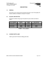
1
CO Guardian LLC
1951 E. AIRPORT DRIVE
TUCSON, AZ. 85706
Document No. 01-2510-02
Date: 11/23/02
REV A
CO Guardian LLC
1951 E. Airport Dr.
Tucson, AZ 85706
CARBON MONOXIDE DETECTOR MODEL 452 INSTALLATION AND
OPERATIONAL MANUAL
Document No. 01-2510-02
MODEL 452 INSTALLATION AND OPERATIONAL MANUAL
Page 1 of 17
CO Guardian LLC
1951 E. AIRPORT DRIVE
TUCSON, AZ. 85706
Document No. 01-2510-02
Date: 11/23/02
REV A
INTENIONALLY LEFT BLANK
MODEL 452 INSTALLATION AND OPERATIONAL MANUAL
Page 2 of 17
CO Guardian LLC
1951 E. AIRPORT DRIVE
TUCSON, AZ. 85706
Document No. 01-2510-02
Date: 11/23/02
REV A
LOG OF REVISIONS
REV
NO.
PAGE
NO.
DATE
IR
1 thru 17
9/15/02
1 thru 17
11/23/02
A
DESCRIPTION
Initial Release
Editorial Changes and
Revised Figure 2 and 5.
Revised Self Test
MODEL 452 INSTALLATION AND OPERATIONAL MANUAL
APPROVED
ASH VIJ
ASH VIJ
Page 3 of 17
CO Guardian LLC
1951 E. AIRPORT DRIVE
TUCSON, AZ. 85706
Document No. 01-2510-02
Date: 11/23/02
REV A
INTENIONALLY LEFT BLANK
MODEL 452 INSTALLATION AND OPERATIONAL MANUAL
Page 4 of 17
CO Guardian LLC
1951 E. AIRPORT DRIVE
TUCSON, AZ. 85706
Document No. 01-2510-02
Date: 11/23/02
REV A
TABLE OF CONTENTS
LOG OF REVISIONS...................................................................................................................................3
TABLE OF CONTENTS ...........................................................................................................................5
DESCRIPTION ............................................................................................................................................7
1.0
GENERAL .....................................................................................................................................7
2.0
PHYSICAL DESCRIPTION...........................................................................................................7
TABLE 1 - Part Numbers......................................................................................................................7
3.0
LEADING PARTICULARS ............................................................................................................7
TABLE 2 - Leading Particulars .............................................................................................................8
4.0
SCOPE..........................................................................................................................................9
5.0
SERVICE FACILITIES ..................................................................................................................9
6.0
INSTALLATION PROCEDURE.....................................................................................................9
FIGURE 1 - Recommended Installation Locations.............................................................................11
FIGURE 2 - Indicator Cutout ..............................................................................................................11
FIGURE 3 - Circuit Breaker Cutout ....................................................................................................12
FIGURE 4 - Installation Schematic.....................................................................................................12
7.0
MAINTENANCE INSTRUCTIONS ..............................................................................................14
8.0
CARBON MONOXIDE DETECTOR SCHEDULED MAINTENANCE .........................................14
9.0
SELF TEST SEQUENCE ............................................................................................................15
10.0
PILOT RESPONSE TO IN-FLIGHT CO ALARM.....................................................................15
11.0
ALERT CYCLE ........................................................................................................................16
12.0
UNIT FAILURE INDICATION: .................................................................................................16
13.0
RS-232 DATA BUSS OPTION ................................................................................................16
14.0
Warranty ..................................................................................................................................16
MODEL 452 INSTALLATION AND OPERATIONAL MANUAL
Page 5 of 17
CO Guardian LLC
1951 E. AIRPORT DRIVE
TUCSON, AZ. 85706
Document No. 01-2510-02
Date: 11/23/02
REV A
FORWARD
This document provides information intended for use by persons who, pursuant to current regulatory
requirements, are qualified to install this equipment. Because equipment and system installations vary
depending on a particular aircraft, this document is intended only as a guideline. If further information is
required, contact:
CO Guardian, LLC
1951 E. Airport Drive
Tucson, AZ 85706
(520) 982-8052
(800) 639-7139
We welcome your comments concerning this document. Although every effort has been made to keep it
free of errors, some may occur. When reporting a specific problem, please describe it briefly and include
the document number, the paragraph/figure/table number, and the page number. Send your comments to
the address above.
MODEL 452 INSTALLATION AND OPERATIONAL MANUAL
Page 6 of 17
CO Guardian LLC
1951 E. AIRPORT DRIVE
TUCSON, AZ. 85706
Document No. 01-2510-02
Date: 11/23/02
REV A
DESCRIPTION
1.0
GENERAL
This section gives a physical and functional description of the CO Guardian CO
Detector indicator as installed in Cessna 172 aircraft.
2.0
PHYSICAL DESCRIPTION
CO Detector indicator flange type front panel unit part numbers are listed in
Table 1.
PART NUMBER
452-101-001
452-101-002
452-101-003
452-101-004
MOUNT
Panel
Panel
Panel
Panel
POWER
14 VDC
28 VDC
14 VDC
28 VDC
DATA BUSS
RS-232 Data Buss
RS-232 Data Buss
None
None
TABLE 1 - Part Numbers
3.0
LEADING PARTICULARS
Table 2 gives the CO Detector leading particulars.
MODEL 452 INSTALLATION AND OPERATIONAL MANUAL
Page 7 of 17
CO Guardian LLC
1951 E. AIRPORT DRIVE
TUCSON, AZ. 85706
Document No. 01-2510-02
Date: 11/23/02
REV A
LEADING PARTICULARS
PARAMETER
SPECIFICATION
PHYSICAL
Dimensions (approximate)
Weight (actual)
3.35 in. X 2.25 in. X 1.50 in.
3.5 oz.
ENVIRONMENTAL
Cooling
Temperature and Altitude
Temperature
Non-operating high temperature
Non-operating low temperature
Operating high temperature
Operating low temperature
Temperature Variation
Altitude
Decompression
Overpressure
Humidity
Operational Shock and Crash safety
Vibration
Magnetic Effect
Power Input
Voltage Spike
Radio Frequency Emission
Electrostatic Discharge
Passive
DO-160D, Category B1
(DO-160D Category B1)
+85 °C
-55 °C
+55 °C
-20 °C
DO-160D, Category B
(DO-160D, Category B1) 25,000 feet
DO-160D, Category B1
DO-160D, Category B1
(DO-160D Category A) 95percent
DO-160D Category B
DO-160D: Category S, Curve M
DO-160D, Category Z
DO-160D, Category B
DO-160D, Category B
DO-160D, Category B
DO-160D, Category A
POWER REQUIREMENTS
Power - 14 VDC Models
Power - 28 VDC models
Dissipation (nominal)
14 and 28 vdc models
Dissipation (maximum)
14 vdc models (heater ON)
28 vdc models (heater ON)
+14 VDC (Nominal 9.0 vdc to 15.1 vdc)
+ 28 VDC (nominal 18.0 vdc to 30.3 vdc)
<1 watt
9 watts
10 watts
TABLE 2 - Leading Particulars
MODEL 452 INSTALLATION AND OPERATIONAL MANUAL
Page 8 of 17
CO Guardian LLC
1951 E. AIRPORT DRIVE
TUCSON, AZ. 85706
4.0
Document No. 01-2510-02
Date: 11/23/02
REV A
SCOPE
The Model 452 Carbon Monoxide Detector is designed to detect, measure, and
provide both a visual and aural alert to the crew of piston engine type aircraft
before the level of carbon monoxide (CO) reaches a critical level.
The installation consists of a single carbon monoxide detector indicator operating
on aircraft DC power. The aircraft supplied power and aircraft wiring is protected
by a 2 ampere, resetable, trip free, type circuit breaker. The Carbon Monoxide
Detector is installed in the existing aircraft instrument panel within view and reach
of the pilot.
The CO Detector contains a Test/Reset button, an aural alarm buzzer, an Amber
LED ALERT annunciator, and a green LED STATUS annunciator.
The carbon monoxide alarm level is calibrated to provide both an aural and visual
alert within 5 minutes or less whenever the carbon monoxide level reaches 50
parts per million (PPM) by volume or above per TSO C48A. The warning time is
shortened at higher levels of CO concentrations and becomes approximately
instant should the carbon monoxide level reach 400 parts per million by volume
(PPM) or above.
In case of a carbon monoxide alert, the pilot can acknowledge the alert and
silence the aural warning while keeping the visual alert until the carbon monoxide
level is again reduced below the alert level. The indicator is automatically reset
when the CO level drops below 50 PPM. There is a three-minute delay at startup
for sensor to stabilize before the unit will sense CO.
5.0
SERVICE FACILITIES
The operator can service all components other than the model 452 units itself at
an FAA certified Repair Station.
NOTE: The sensor requires special gases for testing and calibration. If any
discrepancies are found with the unit during installation or during the
seven-year operational service life, the unit must be returned to CO
Guardian for repair or replacement. After seven (7) years, the unit must be
returned to the manufacturer for CO sensor replacement and re-calibration.
6.0
INSTALLATION PROCEDURE
The following documents the installation criteria of the Carbon Monoxide Detector
MODEL 452 INSTALLATION AND OPERATIONAL MANUAL
Page 9 of 17
CO Guardian LLC
1951 E. AIRPORT DRIVE
TUCSON, AZ. 85706
Document No. 01-2510-02
Date: 11/23/02
REV A
Installation:
•
Install the CO Detector on the instrument panel in view and within reach of the pilot.
•
Insure that the air intake on the front of the CO Detector is not obstructed.
•
Install the CO Detector in a location on the instrument panel without high or
disturbed airflow movement. The CO Detector will detect the presence of CO more
effectively if the unit does not have air blowing over it.
•
Insure that the CO Detector installation area meets the temperature and humidity
ranges listed in the List of Particulars specifications. Temperature and humidity
conditions outside the specification may affect the sensitivity of the alarm.
MODEL 452 INSTALLATION AND OPERATIONAL MANUAL
Page 10 of 17
CO Guardian LLC
1951 E. AIRPORT DRIVE
TUCSON, AZ. 85706
View A-A Circuit Breaker
Document No. 01-2510-02
Date: 11/23/02
REV A
View B-B CO Detector
View C-C Remote Caution Light
FIGURE 1 - Recommended Installation Locations
a.
Gain access to the area, front and back, where the CO Detector is to be
installed. Verify that the unit will not interfere with any other instruments.
b.
Cut to the dimensions shown in Figure 2.
FIGURE 2 - Indicator Cutout
MODEL 452 INSTALLATION AND OPERATIONAL MANUAL
Page 11 of 17
CO Guardian LLC
1951 E. AIRPORT DRIVE
TUCSON, AZ. 85706
c.
Document No. 01-2510-02
Date: 11/23/02
REV A
Install circuit breaker per Figure 3 and wiring per Figure 4. It is recommended
that the circuit breaker be installed on the Avionics Master switch buss. See
Figure 3.
FIGURE 3 - Circuit Breaker Cutout
1.
2.
3.
4.
Notes
Connect to +14 VDC or to +28 VDC power as applicable to aircraft and CO Detector rating.
Twist the power and ground return wires together approximately 6 turns per foot.
Ground power return wires to aircraft structure near circuit breaker panel.
All wire to be MIL-W-22759/16 or equivalent.
FIGURE 4 - Installation Schematic
d.
Mount CO Detector per Figure 2.
e.
With the CO Detector disconnected from the aircraft harness, conduct a
continuity check of the added aircraft wiring.
MODEL 452 INSTALLATION AND OPERATIONAL MANUAL
Page 12 of 17
CO Guardian LLC
1951 E. AIRPORT DRIVE
TUCSON, AZ. 85706
Document No. 01-2510-02
Date: 11/23/02
REV A
f.
Close the CO DETECT circuit breaker and measure aircraft voltage between
pins 1 and 2 of the CO Detector connector. Pull the CO DETECT circuit
breaker and connect the CO Detector connector to the aircraft harness. Close
CO DETECT circuit breaker.
g.
Operational check the unit by verifying the unit comes on with steady green
status LED and with an audible beep from the buzzer. Verify remote alert light
operation.
h.
Reset the unit on the panel and verify the CO Detector comes on with steady
green and with an audible beep from the buzzer.
i.
Verify the unit can be shut off with the circuit breaker.
j.
Unit weights 3.5 oz. Record in Aircraft weight and balance manual.
MODEL 452 INSTALLATION AND OPERATIONAL MANUAL
Page 13 of 17
CO Guardian LLC
1951 E. AIRPORT DRIVE
TUCSON, AZ. 85706
7.0
Document No. 01-2510-02
Date: 11/23/02
REV A
MAINTENANCE INSTRUCTIONS
The carbon monoxide detector and associated equipment consist of certain
parts, which do not require periodic scheduled servicing or periodic scheduled
preventive maintenance. At every power up the system will go through a selfdiagnostic check and will show a green light within 10 seconds if the unit is
working properly.
WARNING: If the model 452 unit shows a blinking Amber light
approximately each second and a flashing Amber external remote light
every 4 seconds, return the unit to CO Guardian for repair or replacement.
No Field repair or service is allowable other than to the aircraft wiring
harness and circuit breaker.
The aircraft wiring harness and circuit breaker shall be included in general visual
inspections for system integrity, security, corrosion and chaffing.
8.0
CARBON MONOXIDE DETECTOR SCHEDULED MAINTENANCE
Scheduled Maintenance Program tasks to be added to the aircraft operator's
appropriate airplane maintenance program are as follows:
a.
Recommended Periodic Scheduled Servicing Tasks:
b.
Recommended Periodic Scheduled Preventative
Maintenance test/checks to determine system condition
and/or latent failures:
None Required.
AT EVERY TIME THE UNIT IS TURNED ON.
Note:
Be sure vents on the faceplate are free of obstructions.
Any failures of the system are evident to the pilot
through a blinking Amber light approximately very 1
second and a flashing Amber external light (if
connected) approximately every 4 seconds.
c.
Recommended Periodic Inspections:
None Required.
d.
Recommended Periodic Structural Inspections
None Required.
e.
Required CO Sensor replacement and calibration.
Every SEVEN (7) YEAR interval.
NOTE
The unit must be returned to the manufacturer for sensor
replacement and recalibration every seven calendar years.
NO FIELD SERVICE OR OVEHAUL of Model 452 IS ALLOWED.
MODEL 452 INSTALLATION AND OPERATIONAL MANUAL
Page 14 of 17
CO Guardian LLC
1951 E. AIRPORT DRIVE
TUCSON, AZ. 85706
9.0
Document No. 01-2510-02
Date: 11/23/02
REV A
SELF TEST SEQUENCE
When power is applied to the Model 452 CO Detector, a self-test routine begins.
The test checks for functionality of the critical components such as the CO sensor,
temperature sensor, and the integrity of the total CO Detector system.
•
•
•
•
•
•
•
The test sequence is as follows:
Alert buzzer beeps twice.
Green light flashes twice.
Remote Amber Alert light flashes once.
Amber Alert light flashes twice.
Alert buzzer beeps once.
Green light ON steady.
Remote Amber Alert light flashes once.
The remote alert light will flash once before the detector mounted Amber alert
light flashes and once after the steady green light in the above sequence. Then
the external Amber light will remain OFF until there is another CO alert or until a
failure of the unit occurs.
10.0
PILOT RESPONSE TO IN-FLIGHT CO ALARM
If the CO Detector aural and visual alarms go off in flight, press the TEST/RESET
button.
If the alarm continues to operate by showing a blinking Amber light on the CO
Detector and the remote Amber light stays on:
•
•
•
•
•
•
Shut off the heater, air conditioning or any other opening to the engine
compartment.
Open a fresh air source immediately.
Don't smoke.
Use 100% oxygen, if possible.
Land as soon as conditions permit.
Be sure the source of the contamination is corrected before further flight
NOTE: Blinking Amber light on the unit itself and the remote Amber light
will stay on until the CO level goes below 50 PPM.
DO not recycle the unit through the circuit breaker, as there is a threeminute delay for the CO sensor to stabilize at each startup.
MODEL 452 INSTALLATION AND OPERATIONAL MANUAL
Page 15 of 17
CO Guardian LLC
1951 E. AIRPORT DRIVE
TUCSON, AZ. 85706
11.0
Document No. 01-2510-02
Date: 11/23/02
REV A
ALERT CYCLE
When the unit detects CO, the following alert cycle is activated:
a. The Amber alert light will flash 4 times; each flash is accompanied by a short
audible beep.
b. There will be a gap of 4 seconds with no light or beep.
c. Again, the Amber alert light will flash 4 times; each flash is accompanied by a
short audible beep.
d. The Amber light flash and audible beep sequence will again be followed by a
gap of 4 seconds with no light or beep.
NOTE
This cycle will continue until the CO level
decreases below acceptable levels.
12.0
UNIT FAILURE INDICATION:
A failure of the CO Sensor, Temperature Sensor, or the Micro-controller will result in
the following failure indications:
•
The Amber LED will continue to flash at an approximately rate of 1 second
on and one second off until the failure is cleared or power is removed from
the unit.
•
The remote Amber light will flash at an approximate rate of one flash each
four (4) seconds until the failure is cleared or power is removed from the
unit.
In case of a failure indication, attempt to clear the failure condition by resetting
the CO Detector. Should the failure condition continue, remove the CO Detector
power by pulling the CO Detector circuit breaker.
13.0
RS-232 DATA BUSS OPTION
The RS-232 Data Buss option is not currently available. When available, the RS232 data buss output will couple CO Detector status information to electronic
display systems with RS-232 input capability.
14.0
Warranty
MODEL 452 INSTALLATION AND OPERATIONAL MANUAL
Page 16 of 17
CO Guardian LLC
1951 E. AIRPORT DRIVE
TUCSON, AZ. 85706
Document No. 01-2510-02
Date: 11/23/02
REV A
WARRANTY COVERAGE: CO GUARDIAN LLC. WARRANTS TO THE ORIGINAL CONSUMER
PURCHASER, THAT THIS DETECTOR WILL BE FREE OF DEFECTS IN MATERIAL AND
WORKMANSHIP FOR A PERIOD OF THREE (3) YEARS FROM DATE OF PURCHASE. THE
MANUFACTURER'S LIABILITY HEREUNDER IS LIMITED TO REPLACEMENT OF THE
PRODUCT, REPAIR OF THE PRODUCT OR REPLACEMENT OF THE PRODUCT WITH A
REPAIRED PRODUCT AT THE DISCRETION OF THE MANUFACTURER. THIS WARRANTY IS
VOID IF THE PRODUCT HAS BEEN DAMAGED BY ACCIDENT, UNREASONABLE USE,
NEGLECT, TAMPERING OR OTHER CAUSES NOT ARISING FROM DEFECTS IN MATERIAL
OR WORKMANSHIP. THIS WARRANTY EXTENDS TO THE ORIGINAL CONSUMER
PURCHASER OF THE PRODUCT ONLY.
Warranty Disclaimers: Any implied warranties arising out of this sale, including but not limited to the
implied warranties of description, merchantability and fitness for a particular purpose, are limited in
duration to the above warranty period. In no event shall the Manufacturer be liable for loss of use of
this product or for any indirect, special, incidental or consequential damages, or costs, or expenses
incurred by the consumer or any other user of this product, whether due to a breach of contract,
negligence, strict liability in tort or otherwise. The manufacturer shall have no liability for any
personal injury, property damage or any special, incidental, contingent or consequential damage of
any kind resulting from gas leakage, fire or explosion.
Some states do not allow limitations on how long an implied warranty lasts, so the above limitation
may not apply to you.
Some states do not allow the exclusion or limitation of consequential or incidental damages, so the
above limitations or exclusions may not apply to you.
Legal Remedies: This warranty gives you specific legal rights and you may also have other rights
that vary from state to state.
Warranty Performance: During the above warranty period, your product will be replaced with a
comparable product if the defective product is returned, postage prepaid, to CO Guardian,
Customer Service Department, 1951 East Airport Drive, Tucson, AZ 85706, together with proof of
purchase date. Please include a note describing the problem when you return the unit. The
replacement product will be in warranty for the remainder of the original warranty period or for six
months, whichever is longer. Other than the cost of postage, no charge will be made for
replacement of the defective product.
Important: Do not attempt to open unit. If unit is opened, warranty will be void.
Your Carbon Monoxide Alarm is not a substitute for property, disability, life or other insurance of
any kind. Appropriate insurance coverage is your responsibility. Consult your insurance
agent.
NOTE
The warranty will be void if the unit is opened or tampered with.
MODEL 452 INSTALLATION AND OPERATIONAL MANUAL
Page 17 of 17