1
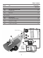
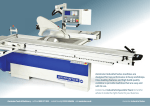
Code 501201 AWFS18 460mm Scroll Saw Index of Contents Index of Contents 02 Declaration of Conformit 02 What’s Included 03-04 Overview of the Scroll Saw 04 General Safety Instructions for 230V Machines 04-05 Additional Safety Instructions for Scroll Saw 05-06 Specification06 Initial Assembly 06-07-08-09 Mounting the Scroll Saw 09 Parts Illustration & Description 10-11-12 Setup/Adjustments13-14 Operating Instructions 15-16-17 Changing the Blade 18-19-20 Maintenance21 Troubleshooting21 Parts Breakdown 22 Parts List 23 Wiring Diagram 24 Manufactured by Chih Chuen Incorporation is in compliance with the following standards or standardisation documents in accordance with Council Directives Copied from CE Certificate The undersigned, authorised by M. Kroger Chih Chuen Incorporation No. 8, Alley 65 Fu-Kuang 5 Lane, Wu-Kuang Rd. Wu-Jih Hsiang, Taichung Hsien 414 Taiwan, R.O.C. • Machinery Directive: 2006/42/EC • Low Voltage Directive: 2006/95/EC • EMC Directive: 2004/108/EC Model number CH-SE 18V Scroll Saw 120W symbols below advise that you follow the correct Warning The safety procedures when using this machine. Fully read manual and safety instructions before use Ear protection should be worn Eye protection should be worn 02 Dust mask should be worn HAZARD Motor gets hot What’s Included Quantity Item 1 No: Axminster White 18” Scroll Saw 1 No: NVR Switch with mounting bracket 1 No: Air Delivery Tube Bag 1 Containing: 1 No: Blade Guard 1 No: Blade Guard Angle Support Rod Bag 2 Containing: 2 No: Spare Blade Clamps 1 No: Spare Table Insert 1 No: 2.5mm, 3mm & 5mm Hex Keys Pack of Saw Blades Containing: 5 No: 18t x 0.35 x 1.4 x 130mm 5 No: 12.5t x 0.5 x 0.94 x 130mm 5 No: 9.5t x 0.6 x 1.62 x 130mm 1 No: Instruction Manual Model Number CH-SE 18V A B C D E F G H I J K I G H J K Plastic air hose F A E 03 B What’s Included of the parts of your scroll saw, which will enable you to become familiar with terminology we will use in this manual. Keep this Instruction Manual readily accessible for any others who may also be required to use the tool. Please read the Instruction Manual prior to using your new tool; as well as the operating procedures for your new tool, there are numerous hints and tips to help you to use the tool safely and to maintain its efficiency and prolong its life. There is also a detailed description Overview of the Scroll Saw clearance around the blade when required. The twin arm design of this saw creates a near perfect parallel action which, when combined with the swivelling blade guide, results in a good clean cutting action suited to a wide range of materials. Fitted with a mushroom Emergency Stop switch positioned within easy reach as required for Educational use. Complies with BS4163-2006. Supplied with table insert and fretsaw blade. A high performance, low-vibration scroll saw with many features and benefits that will be of interest to the serious user. The stroke rate is continuously variable allowing almost any material to be cut (with the right blade fitted). The 20mm deep stroke allows deeper sections of timber to be cut, clean and square every time. The generous sized worktable is fitted with a close fitting insert which supports fine work close to the blade. Additional blank inserts are available for the user to drill out to give the absolute minimum of General Safety Instructions for 230V Machines Good Working Practices/Safety The following suggestions will enable you to observe good working practices, keep yourself and fellow workers safe and maintain your tools and equipment in good working order. WARNING!! KEEP TOOLS AND EQUIPMENT OUT OF THE REACH OF YOUNG CHILDREN Primary Precautions The machine is supplied with a moulded 13 Amp. Plug and 3 core power cable. Before using the tool inspect the cable and the plug to make sure that neither are damaged. If any damage is visible have the tool inspected /repaired by a suitably qualified person. If it is necessary to replace the plug, it is preferable to use an ‘unbreakable’ type that will resist damage on site. Only use a 13 Amp plug, make sure the cable clamp is tightened securely. Fuse at 5 Amp. It is also good practice to use switched outlets. If extension leads are to be used, carry out the same safety checks on them, and ensure that they are correctly rated to safely supply the current that is required for your machine. Work Place/Environment Always mount the machine on a flat, level, stable surface. There are several methods of achieving this, bolting the machine directly to a ‘good solid workbench’, bolting the machine to a sturdy base board that can be clamped to the ‘good solid workbench’; create an independent entity by bolting the machine to its own stand. However you mount your machine, make sure it is fastened down and stable before use. The machine is not designed for sub-aqua operation, do not use when or where it is liable to get wet. If the machine is set up in the open, and it starts to rain (unusual though this would be in U.K.), cover it up or move it into the dry. If machine has got wet; dry it off as soon as possible, with a cloth or paper towel. Do not use 240Va.c. powered machines anywhere within a site area that is flooded or puddled, and do not trail extension cables across wet areas. Keep the machines clean; it will enable you to more easily see any damage that may have occurred. 04 General Safety Instructions for 230V Machines (Under no circumstances should CHILDREN be allowed in work areas) It is good practice to leave the machine unplugged until work is about to commence, also make sure to unplug the machine when it is not in use, or unattended. Always disconnect by pulling on the plug body and not the cable. Once you are ready to commence work, remove all tools used in the setting operations (if any) and place safely out of the way. Re-connect the machine. adequately when not in use to prevent children from damaging themselves by tampering with it. Make sure you are comfortable before you start work, balanced, not reaching etc.. HANDLE WITH EXTREME CARE Whenever transporting or installing machinery, and always use a lifting tool. NEVER STAND ON THE MACHINE. Serious injury could occur if the machine is tipped or if a cutting tool is accidentally contacted. Do not store materials above or near a machine, such that it is necessary to stand on the machine to reach them. If the work you are carrying out is liable to generate flying grit, dust or chips, wear the appropriate safety clothing, goggles, gloves, masks etc., and if the work operation appears to be excessively noisy, wear ear-defenders. If you wear your hair in a long style, wearing a cap, safety helmet, hairnet, even a sweatband, will minimise the possibility of your hair being caught up in the rotating parts of the tool, likewise, consideration should be given to the removal of rings and wristwatches, if these are liable to be a ‘snag’ hazard. Consideration should also be given to non-slip footwear, etc.. AVOID ACCIDENTAL STARTING. Ensure the switch is OFF before plugging in to mains. BE AWARE that accidents are caused by carelessness due to familiarity. ALWAYS concentrate on the job in hand, no matter how trivial it may seem. Do not use this machine within the designated safety areas of flammable liquid stores or in areas where there may be volatile gases. There are very expensive, very specialised machines for working in these areas, THIS IS NOT ONE OF THEM. Do not work with cutting tools of any description if you are tired, your attention is wandering or you are being subjected to distraction. A deep cut, a lost fingertip or worse; is not worth it! Check that blades are the correct type and size, are undamaged and are kept clean and sharp, this will maintain their operating performance and lessen the loading on the machine. Above all, OBSERVE…. make sure you know what is happening around you, and USE YOUR COMMON SENSE. NEVER LEAVE MACHINE RUNNING UNATTENDED. Turn the power OFF. Do not leave machine until it comes to a complete stop. MAKE WORKSHOP CHILDPROOF. Cover the saw Additional Safety Instructions for Scroll Saw 1. Wear safety goggles as protection against flying wood chips and saw dust. In many cases, a full face shield is even better protection. A dust mask is also recommended to keep saw dust out of your lungs. 4. This scroll saw is for indoor use only. 2. The scroll saw must be bolted securely to a stand or workbench. If the saw has a tendency to move during certain operations, bolt the stand or workbench to the floor. 6. Clear the work table of all objects except the workpiece (tools, scraps .rulers etc.) before turning the saw on. 3. A solid wood workbench is stronger and more stable than a workbench with a plywood table. 5. Do not cut pieces of material which are too small to be held by hand. 7. Make sure the blades’ teeth are pointing down, toward the table, and that the blade tension is correct. 05 Additional Safety Instructions for Scroll Saw 8. When cutting a large piece of material, support it at the height of the table. off-cuts from the table. 14. Make sure there are no nails or foreign objects in the part of the workpiece to be sawn. 9. Do not feed the workpiece through the blade too fast. Feed only as fast as the blade will cut. 15. Be extra cautious with very large or small, or irregularly shaped workpieces. 10. Keep your fingers away from the blade. Use a push stick as you near the end of the cut. 16. Set up the machine and make all adjustments with the power OFF, and disconnected from the supply. 11. Take care when cutting a workpiece which is irregular in cross section. Moulding for example must lie flat, and not ‘rock’ on the table as it is being cut. A suitable support must be used. 17. DO NOT operate the machine with the covers off. They must all be in place and securely fastened when performing any operation 12. Take care when backing off a workpiece from the blade, as the blade may bind in the ‘kerf. In this event, switch OFF the machine and disconnect from the supply. Wedge open the kerf, and withdraw the workpiece. 18. Be sure to use the correct blade size and type. 19. Use ONLY approved replacement saw blades. Contact your local Axminster Tool Centre for advice. The use of inferior blades may increase the risk of injury. 13. Switch off the saw, and make sure the blade has come to a complete stop before clearing sawdust or Specifications ModelAWFS18 Product Code 501201 RatingTrade Power120W Throat 460mm(18”) Stroke 10 and 20mm Cuts per Minute 400-1,400 Max Depth of Cut 65mm Table Size 460 x 235mm Table Tilt 0-45° Overall L x W x H 620 x 285 x 310mm Weight29kg Initial Assembly 2) Locate the angle support rod (E) and slide it through the two pre-drilled holes in the cast iron blocks. (See fig 2). Lightly tighten the grub screws. 3) Undo the butterfly bolt on the blade guard (D), line up the pre-drilled hole with the angle support rod (E) and slide it into position. Angle the guard until you are happy, then re-tighten the butterfly bolt. (DO NOT OVERTIGHTEN) (See fig 3) Your scroll saw is fully assembled, except for the Blade Guard, Air delivery tube and NVR switch assembly. To attach these components, you will require a 3 & 5mm allen keys and 17mm spanner, then proceed as follows: Mounting the Blade Guard: 1) Undo the two grub screws on the scroll saw’s cast iron arm blocks using the supplied 3mm allen key. (See fig 1). 06 Initial Assembly Fig 1 Angle support rod Cast iron blocks Fig 2 Grub screws E 3mm Hex key Undo the two grub screws Slide the angle support rod through the two pre-drilled holes & tighten the grub screws Fig 3 Fig 4 D Hex bolts REMOVE the two hex bolts in readiness for mounting the NVR assembly Slide on the blade guard and lightly tighten the butterfly bolt Mounting the NVR Switch Assembly: The NVR switch is mounted to a steel angle bracket (B),to the base of the bracket there are three pre-drilled holes, two of the holes are for fixing the assembly to the fretsaw arm while the third is for securing the air delivery tube (C). You will require a 5mm Hex key and a 17mm spanner. Please follow the instruction below. 1) Loosen and remove the two hex bolts from the cast iron arm. (See fig 4). 2) Line up the two holes in the NVR switch bracket with the pre-drilled holes in the cast iron arm and secure using the two hex bolts you removed earlier. (See figs 5 & 6 on the next page) (DO NOT OVER TIGHTEN) NOTE: You may need to remove the cable covers on the NVR switch to enable a 5mm allen key to gain access to secure the hex bolts. NOTE: Support the arm to stop it from dropping onto the table. 07 Initial Assembly Mounting the NVR Switch Assembly: B Fig 5 Fig 6 Cable cover 5mm Hex key Hex bolt Insert the two hex bolts you removed earlier to secure the NVR assembly You may need to remove the cable covers on the NVR assembly to gain access to the hex bolts Fitting the Air Delivery Tube: 1) Locate the air tube assembly (C), undo and remove the 1/4” BSP brass fitting (See fig 7). Insert the threaded end of the air tube (C) through the pre-drilled hole to the base of the NVR assembly bracket (B). (See fig 8). 2) While holding the air tube (C) in position screw the 1/4” BSP brass fitting back on. (See fig 9). NOTE: The fitting may be tight as it is new, you may require a 17mm spanner to tighten it fully Fig 7 Fig 8 1/4” BSP brass fitting C Undo and remove the 1/4” BSP brass fitting from the air tube assembly Insert the air tube’s threaded end through the pre-drilled hole in the NVR bracket Fig 10 Fig 9 Plastic air hose Screw the 1/4” BSP fitting back on the air tube assembly using a 17mm spanner Push on the plastic air hose onto the end of the brass fitting until it is fully home 08 Initial Assembly Fitting the Air Delivery Tube: 3) Grasp the plastic air hose on the fretsaw (A) and push it onto the 1/4” BSP brass fitting until it’s fully home. (See fig 10). Fig 11 Female Male 4) Finally connect the Male & Female in line connectors from the motor and NVR switch assembly together. (See fig 11). Mounting the Scroll Saw Your scroll saw is provided with three threaded mounted holes (A), see fig 12, it is strongly recommended that you mount the machine to a workbench (See fig 12a) or to a purpose built Fretsaw stand. A pad between the saw and the workbench/ stand is also recommended to reduce vibration. The workbench/stand should be at least 250 x 410mm. Ensure you use flat washers between the bolt head and mounting holes. (DO NOT OVERTIGHTEN) There are two extra holes (B) for added stability if required. NOTE: Fretsaw Stand Only. You may need to add a larger sub-table (MDF or Plywood plate) to give extra support to larger models. Fig 12 B A B A Fig 12a Scroll saw 09 Parts Illustration & Description NVR ON/OFF switch assembly, which puts power to the master ON/OFF switch (GREEN Button) ON (RED Button) OFF Blade tension knob RESET Button Upper blade guard Work table Plastic air hose Air pump (bellows) Scale 0-45˚ Variable speed control unit Dust extraction outlet Pointer Table clamp 10 Lower blade guard Parts Illustration & Description NVR switch shroud Rocker arm Emergency stop Tensioning lever Anti-kick back guide height rod Air delivery tube Clamping knob Guard angle support rod Anti-kick back guide to stop the work kicking back at you. Table insert ON Master ON/OFF switch. Variable speed control knob OFF Variable speed control with step less speed ranging form 400rpm (Low) to 1400rpm (High) 11 Parts Illustration & Description Lower arm Blade symbol X 2 Blade positioning guides Remove the side panel to gain access to the drive assembly Drive bearing NVR Switch with mounting bracket 1/4” BSP brass fitting Motor Scroll saw chassis Plastic air tube Air pump (bellows) Table stop 12 Setup/Adjustments Checking the blade tension: Your fretsaw comes with the blade already fitted, check that the blade is under tension. If the blade is loose, turn the blade tensioning knob to the rear of the rocker arm, one fall turn clockwise, the blade should now be under tension. (See fig 13) Warning: DO NOT over tension the blade otherwise the blade might break when you make your first cut. Checking the blade tension Blade tensioning knob Fig 13a Fig 13 Turn the blade tensioning knob one full turn clockwise to tension the blade Perpendicular (Square) Adjustment: Place an engineer’s square on the table and place it up-against the blade and check that the blade is perpendicular (90˚) to the table, making sure that the square is not in contact with any of the teeth. (See figs 14 & 14a). If adjustment is required follow the instruction below. Table clamp Fig 14 Blade 90˚ degree Square 90˚ 1) Loosen the table clamp, beneath the table. Fig 14a Fig 15 2) Adjust the table until the blade is perpendicular to the table, then re-tighten the table clamp. (DO NOT OVERTIGHTEN) 3) Check that the scale pointer is pointing at 0˚degrees on the scale. If not peel off the arrow sticker and replace it so the arrow is pointing at 0˚. (See fig 15) Scale 13 Pointer Setup/Adjustments Setting the Anti-kick back guide: Place your work on top of the work table and lower the anti-kick back guide by loosening the grub screw on the cast iron block, see figs 16 & 17, so it is just above work piece. Re-tighten the grub screw and lower the blade guard (D). 3mm Hex key Fig 16 Anti-kick back guide clamping screw Fig 17 Work piece Loosen the grub screw which clamps the anti-kick back guide. Position the anti-kick back guide, so it is just above the work piece. Operating Instructions If you are new to scroll saws, there will be a learning period, a period to learn the saw itself, and a period to learn how the wood and saw work together. Expect some blade breakages, scroll saw blades are fairly fragile, compared to blades found on a bandsaw or circular saw. Under no circumstances should CHILDREN be allowed in work areas Make a last check that everything is secure, that the blade is tight and all none essential items have been cleared away from the work area. Connect a dust extraction unit or vacuum cleaner to the dust extraction outlet on the fretsaw. See the cover of the manual for wearing the correct safety protection when using this machine. PLUG IN and switch on the mains Turning “ON” the Scroll Saw: 1. Open the NVR switch shroud and press the “Green Button”, which put power to the master on/off switch, to the front of the variable speed control unit. (See fig 18). NOTE: MAKE SURE the Variable Speed knob is turned down to “LOW”. (See fig 19). 2. Switch on the scroll saw by pressing the master switch to the “ON” position. (See fig 19). 14 Operating Instructions Fig 19 Fig 18 (GREEN Button) ON “ON” “OFF” Press the “GREEN” button to put power to the master ON/OFF switch Turn down the variable speed control knob 3. Increase the speed to 400rpm, place the work piece on the table and supporting it with both hands, SLOWLY guide the work piece forward into the blade. NOTE: You must guide the wood into the blade SLOWLY, because the teeth are very small, and it cuts ONLY on the down wood stroke. If you push the wood into the blade too rapidly, you can easily break the blade. NOTE: If you find the blade is struggling to cut through, increase the speed by turning the variable speed knob until you are happy. 4. Once you have completed your cut, switch off the fretsaw by pressing the master switch to the “OFF” position, see fig 19, turn “OFF” the mains switch. 5. If you have finished using the scroll saw, clean above and below the work table and using a damp cloth wipe the scroll saw over. 6. If the scroll saw is not going to be used for a period of time, smear a light coat of oil over the work table and place a dust sheet over the scroll saw. (Part no: 600410). Tilting the table to 45˚ degrees: 45˚ Loosen the table clamp to tilt the table 0-45˚ then re-tighten the table clamp The table is set to 45˚ degrees as shown on the scale. 15 Operating Instructions In an Emergency: In an “EMERGENCY” “SLAP” down the NVR’s shroud, thus switching the machine off instantly. Fretsaw Operating Characteristics The scroll saw’s unique ability is cutting intricate curves which other saws cannot do. A scroll saw can also be used for straight line cutting such as cross cuts, ripping and bevels. The following is a list of points to remember when using a scroll saw. 4. The teeth on the blade will wear out sooner or later. The blade must therefore be replaced often to obtain the best cutting results. A blade will stay sharp for half an hour to 2 hours of continuous running, depending on the material being cut. 1. The saw does not cut wood by itself. You feed the workpiece into the blade, letting the blade cut the wood as you move the piece ahead. 5. Be aware that the blade has a tendency to follow the grain of the wood. You can compensate for this by watching the grain carefully and guiding the wood past the saw blade. 2. You must guide the wood into the blade SLOWLY, because the teeth are very small, and cut ONLY on the down stroke. If you push the wood into the blade too rapidly, you can easily break the blade. 3. Although the capacity of the saw accepts wood up to 2” thick, better results are obtained with wood no more than 1” thick. For wood thicker than 1”, you must guide the wood into the blade very slowly, taking care not to bend or twist the blade. 6. If you are not familiar with scroll saws, there will naturally be a learning period - a period to learn the saw itself, and a period to learn how the wood and saw work together. Expect some blade breakages, scroll saw blades are fairly fragile not the same types of blade you find on a handsaw or circular saw. Cutting Intricate Patterns: One capability a scroll saw has that other saws do not, is cutting intricate patterns inside a workpiece. To do this, you should adopt the following procedure. 4. Place the workpiece on the table, with the 1/4” hole over the access hole in the table. 1. Drill a 1/4” hole in the middle of the workpiece, in a area which will not be a part of the finished object. 5. Replace the blade, through the hole in the workpiece, (with the teeth pointing downwards), and re-tension the blade. 2. Switch off and unplug the machine from the supply. 6. Plug the saw back in. 3. Remove the blade from the machine. (See pages 17,18 & 19). Check to ensure that the workpiece is not touching the blade before switching ON. 16 Operating Instructions Adjusting the Blade Stroke: On the motor drive wheel there are two pre-drilled holes for adjusting the blade stroke from 10mm to 20mm, please follow the instuctions below for changing the stroke. 1. To gain access to the drive wheel, remove the side panel (A) by undoing the Phillips screw, counter-clockwise, place assembly safely aside. 2. Place a steel rod into the recess to the side of the drive wheel (B), to hold the wheel in position. 3. Undo the lower arm drive bearing using a 8mm socket (C) and reposition to the adjacent hole to change the stroke, re-secure. Note: The left hole is for 10mm strokes and the right for 20mm strokes. B A Undo the side panel to gain access to the drive wheel Motor wheel drive assembly C B Place a steel rod into the recess to the side of the drive wheel (B), to hold the wheel in position Undo the lower arm drive bearing using a 8mm socket The left hole is for 10mm strokes and the right for 20mm strokes Re-secure the lower arm 17 Changing the Blade Changing Standard Blades: DISCONNECT THE SAW FROM THE MAINS SUPPLY 1. Lift up the blade guard (A) and push down the lower guard (B) (beneath the table). 2. Remove the table insert (C). 3. Loosen the tensioning knob (D). 4. Pull the tensioning lever (E) forwards. 5. Loosen the blade clamping knob (F). 6. Press down on the rocker arm and remove the upper blade clamp, from it’s cradle (G). 7. Press down the lower housing clip (H)(beneath the table) and remove the lower blade clamp. 8. REMOVE the blade assembly, through the hole in the table. A C B D E F H G 18 Changing the Blade Changing Standard Blades: 9. Insert the saw blade clamps into the saw blade positioning guides (J), to the right side of the table. 10. Loosen the hex screws (K) on the blade clamps, using a 3mm allen key. REMOVE the blade. 11. Insert a NEW blade into the blade clamp slots (see the blade symbol embossed on the positioning guide). Tighten the two hex bolts to clamp the blade in position. 12. REPLACE the blade assembly as previously described on page 18 in reverse. INSTALL THE BLADES AS RECOMMENDED BY THE MANUFACTURER. J 3mm Allen key K Blade clamp slot Changing Standard Blades (Pin Ends) CLEAN THE UPPER AND LOWER BLADE HOLDER BEFORE INSERTING A NEW BLADE & CHECK THE BLADE FOR DAMAGE. 1. Repeat 1 to 8 on the previous pages, to remove the standard blade. 2. INSERT the pin ended blade through the centre of the table. INSTALL THE BLADES AS RECOMMENDED BY THE MANUFACTURER. 3. Slide the blade into the lower cradle (H) so that the pins on the end of the blade engage in the recess in the housing. (See page 20) 4. Press down the rocker arm and slot the blade through the upper housing and lower the pin ends into the cradle (G). 5. Pull the tensioning lever (E) back. 6. Turn the tensioning knob (D) (ONE FULL TURN CLOCKWISE) 7. Replace the table insert (C). 8. Lower the upper blade guard (A) and push up the lower guard (B) (beneath the table). 19 Changing the Blade Changing Standard Blades: (Pin Ends) Upper cradle G Lower cradle H Blade pins NOTES on Saw Blades: BLADES BREAK FOR FIVE PRINCIPAL REASONS: 1. Too much tension or too little tension on the blade. 2. Overworking the blade by feeding the workpiece too fast. 3. Twisting or bending the blade by feeding the workpiece off-centre. 4. Over use, the blade has reached the end of its useful life. 5. Maximum cutting depth 2”, optimum cuttting depth ¾” for which it was designed. HOW TO DETERMINE THE RIGHT BLADE FOR THE JOB? This fretsaw accepts a wide variety of blade widths and thicknesses. The width of the blade, the thickness of the blade, and the number of teeth per inch (TPI) are determined by the type of material and size of the radius being cut. Here are several examples: TPI WIDTH THICKNESS MATERIAL 10 2.8mm 0.11” 0.5mm 0.020” Medium curves on 114” to 1-3/4” wood, wallboard, hardboard. 15 2.8mm 0.11” 0.5mm 0.020” Same as above, plus wood 1/8” to 1-1/2” thick 18 2.4mm 0.095” 0.25mm 0.010” Extra thin cuts on soft woods to 1/4” and parquetry As a general rule, select the narrowest blades recommended for intricate curve cutting and widest blades for straight and large curve operations. SEE OUR FULL RANGE OF FRETSAW BLADES AND ACCESSORIES IN OUR CATALOGUE. Maintenance 1. Apply a thin coat of paste wax on the work table from time to time. This will help the wood glide across the table more smoothly. 2. After every 50 hours of use, lubricate the lower arm/ drive bearing with 3-IN-ONE oil, (part no. 510053), by removing the side panel of the saw.(See figs 20 & 21). 20 Maintenance 3. The motor is permanently lubricated. Do not try to oil the motor bearings or service any internal parts of the motor. If the power cord is worn, frayed, cut or damaged, contact Axminster Power Tool Centre. Do not try to patch it up with electrical tape, this could lead to more trouble. Fig 20 Fig 21 Lower arm OIL To gain access to the drive bearings, remove the side panel by undoing the Philips screw, counter-clockwise. Once you have removed side panel lubricate the lower arm/drive bearing with 3-IN-ONE oil. 4. Frequently blow out any dust that may accumulate inside the motor. An occasional light coat of oil on the table to prevent surface rust is recommended. 5. Occasionally wipe the machine over with a damp cloth. 6. If the fretsaw is not going to be used for a period of time, smear a light coat of oil over the work table and place a dust sheet over the fretsaw. (Part no: 600410). Troubleshooting PROBLEM Breaking Blades Motor Will Not Run Excessive Vibration (Some vibration is inevitable when the saw and motor are running) Blade Runout PROBABLE CAUSES 1. Incorrect tension. 2. Overworked (worn out) blade. 3. Wrong blade being used. 4. Twisting blade in wood. 1. Defective cord,plug or outlet 2. Defective motor. 1. Improper mounting of saw. 2. Unsuitable mounting surface. 3. Loose table. 4. Motor mount is loose. 1. Blade clamps not aligned. (Blade not in line with motion of Rocker Arms). 21 SUGGESTED REMEDY 1 Adjust blade tension. 2. Reduce feed rate or replace blade. 3. Use narrow blades for thin wood, wider blades for thicker wood. 4. Avoid side pressure on blade. 1. Unplug saw, replace defective parts. 2. Repairs MUST be made by a qualified technician. Call Axminster Tool Centre. (Technical Sales Phone: 08700 600388). 1. See proper mounting instructions. 2. Replace plywood workbench surface with solid lumber surface. 3. Tighten table clamping knob. 4. Tighten motor mount screws. 1. Loosen the blade clamping knob (F). Adjust position of blade clamps. Use a 90˚ square to verify alignment. Re-tighten clamping knob (F) & continue operation. Parts Breakdown 22 Parts List 23 Wiring Diagram Axminster Tools & Machinery Ltd Weycroft Avenue, Axminster, Devon EX13 5PH axminster.co.uk 24