1
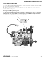
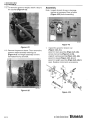
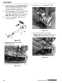
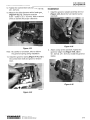
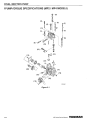
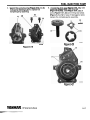
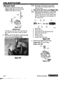
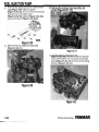
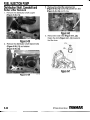
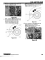
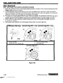
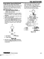
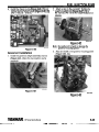
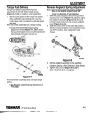
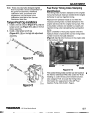
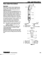
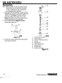
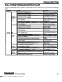
FUEL INJECTION PUMP
4. lnspect the pump housing (Figure 5-19, (1,2)).
If the pump housing is worn, replace the
complete pump assembly.
5. lnspect the drive gear (Figure 5-20, (I)), rotor
assembly (Figure 5-20, (2)), drive pin
(Figure 5-20, (3)), seal (Figure 5-21, (2)) oil
ports (Figure 5-21, (3)) and O-ring seal areas
(Figure 5-21, (1)) for wear. If damaged or worn,
replace the complete pump assembly.
0003559
Figure 5-20
Figure 5-19
Figure 5-21
mNMAR.
MP Series Service Manual
FUEL INJECTION PUMP
Note: Be careful not to lose the secondary
check balls during disassembly of the
delivery valves.
Hydraulic Head
1. Mark the positions of the fuel inlet
(Figure 5-22, (1)) and return fittings
(Figure 5-22, (2)) and remove.
3. Disassemble each delivery valve (Figure 5-24).
Note: Keep and identify all parts in order during
disassembly. Do not mix valve parts. If
reused, each valve must be reassembled
with the original parts and reinstalled in
the original port.
Figure 5-22
IMPORTANT
The delivery valve has many parts that are
very small. Do not drop or lose the check
valve.
2. Remove each of the delivery valve housings
valves and gaskets (Figure 5-23).
1.
2.
3.
4.
5.
6.
7.
Valve Seat
Return Spring
Secondary Check Ball Spring Seat
Secondary Check Ball
Delivery Valve
Primary Spring
Delivery Valve Housing
Figure 5-24
4. Remove the distribution shaft plug
(Figure 5-25, (I)), and O-ring
(Figure 5-25, (2)).
0001 181
Figure 5-23
GO03552b
Figure 5-25
MP Series Service Manual
YANMAR,
FUEL INJECTION PUMP
IMPORTANT
Do not use magnetized tools, as this may
cause fuel pump components to become
magnetized and attract metal debris.
5. Remove the distribution shaft (Figure 5-26).
7. Note the position of the coolant fitting
(Figure 5-28, (3)) and remove the coolant plug
(Figure 5-28, (I)), gasket (Figure 5-28, (2))
and fitting. Remove the thermo-element
assembly (Figure 5-28, (4)), which includes the
timer piston (Figure 5-28, (5)), timer piston
return spring (Figure 5-28, (6)) timer housing
(Figure 5-28, (7)), gaskets (Figure 5-28, (8))
and seal (Figure 5-28, (9)).
0001 185
Figure 5-26
Note: Store parts in clean oil to prevent
oxidation.
6. Remove the plunger and barrel plug
(Figure 5-27, (I)), O-ring (Figure 5-27, (2))
and copper seal (Figure 5-27, (3)).
0003551
Figure 5-28
Figure 5-27
YANMAR, MP series service Manual
-
-
FUEL INJECTION PUMP
Remove the charge pump fuel outlet strainer
plug (Figure 5-29, (1)) and gasket
(Figure 5-29, (2)). Do not remove the strainer.
Remove the accumulator plug
(Figure 5-29, (3)) washer (Figure 5-29, (4)),
spring and piston (Figure 5-29, (5,6)).
10. Remove the hydraulic head assembly and
gasket (Figure 5-31, (1)).
0003554
Figure 5-29
Remove the four hydraulic head bolts
(Figure 5-30, (1)).
Figure 5-31
11. Use the spring compressor tool
(Figure 5-33, (2)) (Included in Yanmar Special
Tool Kit P/N 458091) to compress the plunger
spring (Figure 5-32, (1)) and remove the spring
retainer (Figure 5-33, (1)).
0001193A
Figure 5-30
Figure 5-32
MP Series Service Manual
YANMAR
FUEL INJECTION PUMP
14. Remove the spring retainer (Figure 5-36, (I)),
control sleeve (Figure 5-36, (2)) and plunger
(Figure 5-36, (3)).
1. Spring ~ e t a i n e r '
2. Spring Compressor Tool
3. Hydraulic Head
Figure 5-33
12. Remove the control rack return spring
(Figure 5-34, (1)).
00001 2 17
Figure 5-36
Note: Store all valves (Figure 5-37) removed
from hydraulic head assembly in clean oil
to prevent oxidation.
0001214a
Figure 5-34
13. Remove the control rack guide and bolts
(Figure 5-35, (1)).
i
0001220
Figure 5-37
00001215a
Figure 5-35
YANMAR. MP series service Manual
-
..
. .-
L
FUEL INJECTION PUMP
Distribution Shaft. Camshaft and
Roller Lifter Removal
3. Remove the roller lifter alignment pin
(Figure 5-40, (1)) and O-ring and the link lifter
(Figure 5-40, (2)) and O-ring.
1. Remove the distribution shaft coupler
(Figure 5-38, (1)).
Figure 5-40
0001196
Figure 5-38
4. Remove the roller lifter (Figure 5-41, (2)).
Retain the shim (Figure 5-41, (1)) located in
the lifter bore.
2. Remove the distribution shaft retainer bolts
(Figure 5-39, (1)) and retainer
(Figure 5-39, (2)).
.
_...-_
i
_
Figure 5-41
Figure 5-39
5-22
MP ~ e r ~ ~ervlce
es
Manual
YANMAFI,
FUEL INJECTION PUMP
Remove the camshaft bearing retainer bolts
and retainer (Figure 5-42, (1)).
(MP4 Model Pump) Align the camshaft keyway
(Figure 5-44, (2))with the embossed mark
(Figure 5-44, (1))on the body.
Figure 5-42
-
(MP2 3 Cylinder Model Pumps) Align the
camshaft keyway (Figure 5-43, (1))with the
appropriate timing mark on the body
3 Cylinder Model (Figure 5-43, (2))or
4 Cylinder Model (Figure 5-43, (3)).
Figure 5-44
Lift the distribution shaft (Figure 5-45, ( 1 ) )
slightly and pull out the camshaft
(Figure 5-45, (2))being careful to avoid
damaging the camshaft lobes.
Figure 5-43
Figure 5-45
YANMAR* MP series service Manual
FUEL INJECTION PUMP
9. Remove the distribution shaft assembly
(Figure 5-46).
FUEL PUMP REASSEMBLY
Distribution Shaft and Camshaft
1. Invert the pump body and apply assembly
grease to the distribution shaft and gears
(Figure 5-47, (1)) before installing it into the
pump body.
Note: Check that the distribution shaft rotates
freely after installation.
0001210
Figure 5-46
0001237
Figure 5-47
2. Apply assembly grease to the camshaft lobes,
bushing journal and ball bearing.
5-24
MP series service Manual
YANMAR
FUEL INJECTION PUMP
3. With the distribution shaft gear touching the
pump body, insert the camshaft into the body.
During installation prevent the cam lobes from
hitting the distribution shaft gear and the
camshaft key from hitting the camshaft bushing.
(Figure 5-48).
4. Install the camshaft bearing retainer and bolts
(Figure 5-49, (1)) and tighten to 6 - 7 ft-lb.
(8 - 10 N.m).
-.
Note: 4-cylinder camshafts require special care
during reassembly due to tight
tolerances.
Figure 5-49
0001239
Figure 5-48
VANMAR. MP series service Manual
5-25
FUEL INJECTION PUMP
Gear Alignment
Note: Verify model of fuel injection pump before proceeding
1. Rotate the camshaft to the correct angle (aligning keyway to marks) for the model pump being serviced
(Figure 5-50) and hold in position.
2. Look through the charge pump opening in the case and slightly lift the distribution shaft and rotate to
align the distribution shaft gear and camshaft gears marks. Once the marks are aligned, do not raise the
distribution shaft too far or the gears will disengage and misalign.
3. The gears are properly aligned when the gear marks are aligned, the distribution shaft drive lugs are in
parallel alignment with the retainer screws and the camshaft keyway is at proper angle from step 1.
4. While holding the gear alignment, install the distribution shaft retaining plate and tighten screws to
6 - 7 ft-lb. (8 - 10 N-m).
5. Verify proper gear alignment by checking gear timing marks for proper alignment.
Distribution Shaft Angle
Camshaft Angle MP2 - 3 Cyl.
Camshaft Angle MP2 - 4 Cyl.
'.
PI
0003556A
0001207BB
1. Retaining Plate
2. Distribution Drive Shaft Lugs
W1207B
3. Housing Timing Marks
4. Camshaft Key
Camshaft Angle MP4
0001207CC
Figure 5-50
MP Series Service Manual
YANMAR,
FUEL INJECTION PUMP
Roller Lifter
Plunger and Control Rack
1. lnstall the link lifter (Figure 5-51, (1)) and
1. Install the plunger (Figure 5-53, (1)) into the
O-ring.
2. Install the roller lifter (Figure 5-51, (2)) with the
groove on the side of the lifter aligned with the
lifter alignment pin hole.
head assembly.
0001248A
Figure 5-51
Figure 5-53
3. With roller lifter groove aligned, install the roller
lifter alignment pin (Figure 5-52, (1)). Slowly
tighten the pin by hand (4 mm hex wrench)
while turning camshaft to ensure the lifter
moves freely with pin in position. Torque the pin
to 3 - 4 ft-lb. (4 - 5 N-m). Lifter must move freely
after pin is torqued.
2. Install the control sleeve (Figure 5-55, (2))
aligning the plunger identification marking
(example: "W4") (Figure 5-54, (4)) with the ball
(Figure 5-54, (2)) of the control sleeve.
1. Upper Lead
2. Ball
3. Sub-lead
0001249
Figure 5-52
YANMAR. MP series service Manual
4. Identification
Marking
Figure 5-54
FUEL INJECTION PUMP
-
--
--
-
3. Install the spring retainer (Figure 5-55, (1)).
5. Installing the slide into the spring retainer
(Figure 5-57, (I)), (Figure 5-58, (1)).
0000 12338
1. Spring Retainer
2. Control Sleeve
3. Plunger
00001217
Figure 5-57
Figure 5-55
4. Install the control rack guide (Figure 5-56, (2))
into the corresponding positions (hole and pin)
on the spring retainer (Figure 5-56, (1)). Also
see Figure 5-57 and Figure 5-58.
Figure 5-58
Install and tighten the four bolts
(Figure 5-59, (1)) to 2 - 3 ft-lb. (3 - 4 N-m).
00001233A
Figure 5-56
00001215a
Figure 5-59
MP Series Service Manual
YANMAR*
FUEL INJECTION PUMP
7. Measure the rack (Figure 5-60, (4)) movement,
the range of rack motion should be
approximately 14 mm of total travel.
8. Measure rack backlash, the total backlash
should be equal to or less than 0.008 in.
(0.2 mm). If the backlash is excessive, replace
the rack assembly and control sleeve.
9. Install the rack return spring (Figure 5-61, (1)).
The spring must be able to return the rack from
the maximum decreased fuel position to the
maximum increased fuel position.
Figure 5-61
10. Install the plunger spring (Figure 5-62, (1)) and
spring retainer (Figure 5-62, (2)). Use the
spring compressor tool (Figure 5-63, (2))
(Included in Yanmar Special Tool Kit PIN
458091) to compress the plunger spring and
install the spring retainer.
1. Control Rack
Guide
2. Control Sleeve
3. Rack Auxiliary
Spring
4. Rack
5. Upper Spring
Retainer
6. Distribution Shaft
Sleeve
Figure 5-60
OKl12128
Figure 5-62
YANMAR,,MP Series Service Manual
FUEL INJECTION PUMP
13. Install the original plunger shim(s)
(Figure 5-66, (1)) inside the lifter.
0001213
1. Spring Retainer
2. Spring Compressor Tool
3. Hydraulic Head
Figure 5-631
11. Install the distribution shaft coupler
(Figure 5-64, (1)).
Figure 5-66
14. Install the hydraulic head assembly and
temporarily tighten the (6 mm hex) head bolts
evenly in the order as shown (Figure 5-67, (1,
2, 3,4)) until the surfaces of the head and.the
pump body contact each other. Then tighten to
torque of
(MP2 - 13 - 16 ft-lb. (18 - 22 N.m))
(MP4 - 21 - 24 ft-lb. (28 - 32 N-m)) in a diagonal
order.
Figure 5-64
12. Install a new head gasket (Figure 5-65, (1)).
0001259
Figure 5-67
Figure. 5-65
5-30
MP series service Manual
YANMAR,
FUEL INJECTION PUMP
Plunger (Bottom Clearance) Measurement
The MP fuel pump injection timing is set by
adjusting the plunger height. This is accomplished
using shims in the roller lifter body to move the
plunger up or down (bottom clearance) from the
camshaft base circle.
5. Using shims from the shim kit in the Yanmar
Parts Catalog (MP2 - PIN 158553-51250),
(MP4 - PIN 129906-51400), increase or
decrease the shim pack (Figure 5-69, (3)) in
the roller lifter bore to obtain the zero
mark (+ 0.03 mm) on the dial indicator.
Note: Do not use the ball tip on the dial
indicator when measuring, use the dial
indicator extension alone.
1. Mount the dial indicator (from Yanmar Special
Tool Kit PIN 458091) in the adapter and thread
into barrel.
2. Position the camshaft with the roller lifter at the
bottom of the cam profile.
3. Remove the dial indicator and adapter and zero
the dial indicator (Figure 5-68, (1)) using the
specified spacer (Figure 5-68, (2)). The correct
size spacer can be found in the calibration data
sheet (bottom clearance [mm]) for each pump
number.
U
1. Barrel
2. Plunger
3. Shim(s)
Figure 5-69
0001314AA
1. Dial Indicator
2. Plunger Spacer
3. Flat Surface
Figure 5-68
4. Reinstall the dial indicator (Figure 5-69, (4))
into the barrel (Figure 5-69, (1)) and record the
measurement.
YANMAR, MP series service Manual
0001315A
4. Dial Indicator
5. Plunger
Adjustment
Dimension "An
FUEL INJECTION PUMP
Hydraulic Head and Valve(s)
Reassembly
Install new delivery valve seat seal(s)
(Figure 5-71, (1)).
1. Set the camshaft to the correct angle as used
during the gear alignment.
2. Lubricate the distribution shaft.
3. Align the drive lugs on the bottom of the
distribution shaft and install to engage the
distribution shaft coupler.
Note: The flat on the distribution shaft
(Figure 5-70, (1)) should face toward the
engine side of the pump (or away from
the accumulator piston side).
4. Install the distribution shaft plug
(Figure 5-70, (3)) and O-ring (Figure 5-70, (2))
and tighten to 11 ft-lb. (15 N-m).
M01274
Figure 5-71
Assemble and install each delivery valve
(Figure 5-72).Tighten each delivery valve
housing to 30 - 33 ft-lb. (40 - 45 N.m).
Figure 5-70
Note: Some old style hydraulic heads have a
distribution shaft plug with a flat bottom.
The replacement will require a new plug
to allow clearance for the taller
distribution shaft. The parts catalog lists
the new plug with a machined recess on
the bottom.
1.
2.
3.
4.
5.
6.
7.
Valve Seat
Return Spring
Secondary Check Ball Spring Seat
Secondary Check Ball
Delivery Valve
Primary Spring
Delivery Valve Housing
Figure 5-72
7. Install the charge pump fuel outlet strainer
gasket (Figure 5-73, (2)) and tighten the plug
(Figure 5-73, (1)) to
16 - 21 ft-lb. (25 - 29 N.m).
5-32
MP series service Manual
VANMAR.
FUEL INJECTION PUMP
8. lnstall the accumulator piston (Figure 5-73, (6))
and check that it moves freely. lnstall the spring
(Figure 5-73, (5)), seal (Figure 5-73, (4)) and
tighten the plug (Figure 5-73, (3))
to 37 - 4lft-lb. (50 - 55 N.m).
10. lnstall a new seal (Figure 5-75, (9)) into the
head. lnstall new O-rings (Figure 5-75, (8)) on
the timer housing (Figure 5-75, (7)) and install
the timer housing tightening to
30 - 33 ft-lb. (40 - 45 N-m).
11. lnstall the timer spring (Figure 5-75, (6)) and
piston (Figure 5-75, (5)) into the housing.
Figure 5-73
9. lnstall a new timer housing seal
(Figure 5-74, (1))
Figure 5-75
0001279
Figure 5-74
YANMAReMP Series Service Manual
5-33
FUEL INJECTION PUMP
12. Install a new O-ring (Figure 5-76, (2)) on the
thermo-element (Figure 5-76, (1)) and tighten
to 22 - 26 ft-lb. (30 - 35 N-m).
Do not over-torque.
Charge Pump
Note: If charge pump was disassembled for
inspection, clean all parts thoroughly
before reassembly. If any part is
suspected of damage or failure, replace
the complete pump assembly.
1. lnstall and align pump gears (Figure 5-78, (1))
into pump housing.
2. lnstall the new pump housing O-ring
(Figure 5-78, (2)) into groove and assembly
pump housings. Tighten the two (5 mm hex)
pump housing screws (Figure 5-78, (3)) to
6 - 7 ft-lb. (8 - 10 N-m).
Figure 5-76
13. lnstall the engine coolant fitting
(Figure 5-75, (3)) and seals in their original
position.
14. lnstall the coolant plug (Figure 5-75, (1)) and
tighten to 16 - 18 ft-lb. (22 - 25 N-m). Do not
over-torque.
15. lnstall the fuel return (Figure 5-77, (2)) and
inlet fittings (Figure 5-77, (I)), seals and plugs
to positions marked in disassembly.
0003559A
Figure 5-78
lnstall new charge pump housing O-rings
(Figure 5-79, (1)).
Figure. 5-77
Figure 5-79
5-34
MP Series Service Manual
YANMAR,
FUEL INJECTION PUMP
4. Install the charge pump (Figure 5-80, (1)) and
tighten the four mount screws (Figure 5-80, (2))
to 6 - 7 ft-lb. (8 - 10 N.m).
2. Attach a stop to the camshaft. Tighten the
governor weight nut (Figure 5-82, (1)) to
58 - 62 ft-lb. (79 - 84 N-m). Install the governor
sleeve.
0001251a
Figure 5-82
Note: Be careful not to bend or damage the
governor housing gasket.
Figure 5-80
3. Align and install a new governor housing gasket
(Figure 5-83, (1)).
Governor Installation
1. Install the governor weight assembly and nut
(Figure 5-81, (1)) to the fuel injection pump
camshaft.
Figure 5-81
00013Wa
Figure 5-83
YANMAR, MP Series Service Manual
-
-~
5-35
--
-
--
--
FUEL INJECTION PUMP
4. Turn the link lifter plate counterclockwise to the
6 o'clock position and install the governor
assembly and link into the pump body
(Figure 5-84).
1. Control Rack
2. Governor Link
3. Link Lifter
4. During Assembly
5. During Operation
Figure 5-85
00013Ma
Figure 5-84
Note: Do not force the link during installation,
as damage can occur to the link and
control rack pin.
6. Install two governor housing bolts by hand to
hold the governor in place.
7. While pushing the governor lever assembly to
the full stop position through the stop solenoid
opening, rotate the link lifter clockwise to the
12 o'clock position.
Note: Figure 5-85 illustrates the governor link
connection to the control rack. The
actual connection is blind, therefore this
illustration is used to assist during
assembly.
8. Verify the link installation by watching plunger
rotation from the top of the hydraulic head. The
plunger should rotate in both directions while
moving the control rack in and out.
5. While installing the governor assembly, slide
the link lifter as shown (Figure 5-85,4), to allow
the link to slide in to align with the control rack
pin.
9. Install a new copper seal (Figure 5-86, (3)),
plunger and barrel plug (Figure 5-86, (1)) and
O-ring (Figure 5-86, (2)). Tighten to
(MP2 - 22 - 26 ft-lb. (30 - 35 N.m))
(MP4 - 33 - 37 ft-lb. (45 - 50 N.m)).
Figure 5-86
5-36
MP Series Service Manual
YANmAR
FUEL INJECTION PUMP
10. Tighten the link lifter retainer bolt
(Figure 5-87, (1)) to 6- 7 ft-lb (8 - 10 N.m).
12. Install a new O-ring (Figure 5-89, (1)) to the
stop solenoid and install the stop solenoid to
the governor housing. Tighten the solenoid
bolts to 6 - 7 ft-lb (8 - 10 N-m).
OD01 304a
Figure 5-87
11. Install the governor housing screws and tighten
to 6 - 7 ft-lb (8 - 10 N-m) (Figure 5-88).
0001306a
Figure 5-89
13. Pre-set the adjustment of the angleich . .
assembly, by loosing the angleich lock nut
(Figure 5-90, (1)).
0001305a
Figure 5-88
0001306C
Figure 5-90
14. Turn the angleich adjustment screw in until it
contacts the governor lever and then back out
one-quarter (114) turn.
15. Tighten the angleich lock nut.
YANMAR. MP series service Manual
5-37
FUEL INJECTION PUMP
I
16. Install a new governor housing cover gasket
(Figure 5-91).
0001307a
Figure 5-91
17. Install the governor housing cover to the case
(Figure 5-92). Tighten the governor housing
cover bolts to 6 - 7 ft-lb (8 - 10 N-m).
0001308a
Figure 5-92
5-38
MP series service Manual
YANMAR*
Section 6
ADJUSTMENT
Page
Introduction................................................................................ 6-3
Setup and Inspection....................................................................... 6-3
Adjustment ...................................................................................... 6-4
Component Identification........................................................... 6-4
High Idle Fuel Delivery .............................................................. 6-4
Rated Fuel Delivery ................................................................ 6-4
Torque Fuel Delivery ................................................................. 6-5
Reverse Angleich Spring Adjustment ........................................ 6-5
Low Idle Fuel Delivery ............................................................... 6-6
Start Fuel Delivery ..................................................................... 6-6
Ultra-Low Speed Delivery ........................................................ 6-6
Stop Fuel Delivery ..................................................................... 6-6
Tamper-Proof Cap Installation...................................................6-7
Fuel Pump Timing Index Stamping Identification ...................... 6-7
YANMAR. MP Series Service Manual
ADJUSTMENT
This Page Intentionally Left Blank
MP Series Service Manual
YANMAR.
ADJUSTMENT
INTRODUCTION
This section of the Service Manual describes the
adjustment procedures necessary to setup and
adjust the fuel injection pump and governor.
3. Mount the fuel injection pump (Figure 6-2) on
the pump tester platform.
The fuel injection pump delivery must be calibrated,
whenever the pump is disassembled.
A fuel pump test bench (Figure 6-1) is required to
make the necessary adjustments.
I
SETUP AND INSPECTION
I
1. Verify adjusting nozzle assembly and injection
I
starting pressure.
Figure 6-2
4. Remove the oil fill plug on the top of the
governor case. Fill (Figure 6-3, (1)) the pump
with about 6.75 oz (200 cc) of pump oil or
engine oil.
Figure 6-1
Figure 6-3
5. Securely tighten all fuel lines to the fuel pump
and tester.
2. Inspect the high pressure injection line.
0.08 in.
(2.0 mm)
Inner diameter
Outer diameter x length
0.24 x 23.62 in.
(6.0 x 600 mm)
Minimum bending radius
0.98 in.
(25 mm)
6. Set the oil feed pressure (Figure 6-4) at
2.8-4.3 psi (19.6 - 29.4 kPa, 0.2 - 0.3 kgf/cm2),
temperature at 40 2°C (104 3.6"F).
*
Figure 6-4
7. Operate the pump tester to purge the fuel lines
of all air.
YANMAR
MP series service Manual
ADJUSTMENT
ADJUSTMENT
High ldle Fuel Delivery
The adjustment of fuel delivery requires correct
specifications. Before performing any of the
adjustments in this section, obtain the correct
calibration data sheet for the fuel injection pump
being tested. Contact your Yanmar Fuel Injection
Equipment Central Distributor to obtain the data
sheet.
1. Set the fuel pump speed at the high idle speed
specified. (See Calibration Data Sheet).
Adjustments must be performed in the following
order when adjusting the governor:
1. High ldle Fuel Delivery
2. Rated Fuel Delivery
3. Torque Fuel Delivery
4. Reverse Angleich Spring Adjustment
5. Low ldle Fuel Delivery
6. Starting Fuel Delivery
7. Stop Fuel Delivery
2. Set the control lever (Figure 6-5, (6) to the high
idle position while turning the high idle speed
limit bolt (Figure 6-5, (3)) to obtain the specified
injection amount. (See Calibration Data Sheet).
3. Tighten the lock nut after completing the
adjustment to lock the high idle speed limit bolt
from turning.
Rated Fuel Delivery
The MP2 pump has a rated fuel limiter adjustment
assembly Figure 6-6 as standard equipment.
1. Remove the tamper-proof cap and screw in the
fuel limiter assembly (Figure 6-6, (1)) until it
contacts the governor tension lever and then
back off one-quarter (114) turn.
8. Re-check Rated Fuel Delivery
9. Tamper-Proof Cap Installation
Component Identification
0003465m
Figure 6-6
2. Set the pump speed at the rated speed (see
Calibration Data Sheet) and move the control
lever until it contacts the high idle speed limit
bolt (Figure 6-5, (3)).
1.
2.
3.
4.
5.
6.
Rated Fuel Limiter Adjustment Assembly
Starting Fuel Adjustment Assembly
High ldle Speed Limit Bolt
Reverse Angleich Adjustment Assembly
Low ldle Speed Limit Bolt
Control Lever
3. Adjust the rated injection amount by turning the
fuel limiter assembly (Figure 6-6, (1)) in or out
to obtain the correct specification, (See
Calibration Data Sheet).
Figure 6-5
MP Series Service Manual
ADJUSTMENT
Torque Fuel Delivery
Reverse Angleich Spring Adjustment
Torque fuel delivery adjustment requires
adjustment of the fuel limiter torque spring
(Figure 6-7, (3)) or angleich, when applicable.
Note:) Do not thread past the reverse angleich
lever or the reverse angleich lever will
move in a direction of fuel reduction.
1. Set the pump speed at the torque rise speed
(See Calibration Data Sheet) and move the
control lever until it contacts the high idle speed
limit bolt.
1. With the pump stopped, remove the governor
housing rear cover (Figure 6-9, (1)) and adjust
the angleich assembly (Figure 6-8, (1)) until
If the fuel limiter assembly has a torque spring:
Screw in the fuel limiter torque spring
adjustment screw (Figure 6-7, (4)) to obtain
the specified injection amount (See Calibration
Data Sheet) and fasten the lock nut.
contact is just made with the reverse angleich
lever (Figure 6-9, (4)).
2. Shift the control lever to the high idle position.
Set the fuel pump speed to the specified torque
rise RPM number. (See Calibration Data
Sheet).
00034651
Figure 6-8
3. Set the angleich assembly to the specified
injection quantity. (See Calibration Data Sheet).
4. Tighten the lock nut (Figure 6-8, (2)) to
24.5 - 29.4 N-m (2.5 - 3.0 kgf.m).
0003465p
Figure 6-7
If the fuel limiter assembly does not have torque
spring:
See Reverse Angleich Spring Adjustment on
this page.
YANMAR, MP series service Manual
ADJUSTMENT
Start Fuel Delivery
5. Recheck the rated fuel delivery.
1. Set the pump speed at the specified starting
injection RPM (see Calibration Data Sheet),
and set the control lever at the high idle
position.
2. Turn the starting fuel adjustment bolt
(Figure 6-11, (1)) to obtain the specified
injection amount. (See Calibration Data Sheet)
3. Tighten the locknut (Figure 6-1 1, (2)) and
install the hex cap.
(3)
1. Governor Rear
Cover
2. Reverse Angleich
Spring
000 1324
3. Governor Tension
Lever
4. Reverse Angleich
Lever
Figure 6-9
Low Idle Fuel Delivery
1. Set the pump speed at the low idle pump speed
(see Calibration Data Sheet) with the control
lever (Figure 6-10, (1)) in the idle position.
2. Turn the low idle speed limit bolt
(Figure 6-10, (2) to achieve the correct idling
delivery amount. (See Calibration Data Sheet)
3. Tighten the lock nut.
Figure 6-11
Ultra-Low Speed Delivery
1. Set the pump speed at 50 RPM and check the
ultra-low speed setting injection volume
specification. (See Calibration Data Sheet)
Note: The Ultra Low Speed Test checks the
condition of the plunger and barrel.
Delivery below specifications indicates
excessive leakage.
Stop Fuel Delivery
Set the control lever at the high idle position.
1. Set the pump speed at 50 RPM higher than the
specified high idle speed (see Calibration Data
Sheet) and check that the (governor cut out)
injection amount reduces to zero. (See
Calibration Data Sheet)
0003465h
2. Set the pump at the rated speed and turn off the
stop solenoid and check that the injection
amount reduces to zero.
Figure 6-10
MP Series Service Manual
YANMAR.
ADJUSTMENT
Note: There are a few turbo charged engines
that incorporate a boost compensator on
the governor assembly. Additional
calibration data, procedures and
adjustments can be found in the
calibration data field of the Yanmar
Distributor Web Site.
Tamper-Proof Cap Installation
1. Install a new tab washer (Figure 6-12, (1)) and
tamper-proof cap (Figure 6-12, (2)) on the fuel
limiter assembly.
2. Install a new tamper-proof cap
(Figure 6-13, (1)) on the high idle adjustment
assembly.
Fuel Pump Timing lndex Stamping
Identification
The timing index numbers stamped on the original
fuel pump hydraulic head are needed for the engine
technician to set fuel injection timing.
Replacement hydraulic heads do not have the
necessary timing index numbers stamped on the
engine side boss like the original fuel pumps. The
timing index numbers are needed to properly set
injection timing when reinstalling the fuel injection
pump.
Upon completion of fuel pump repairs when the
hydraulic head is replaced the correct timing index
number must be manually stamped
(Figure 6-14, (1)) onto the boss on the engine side
of the hydraulic head.
0003465q
Figure 6-12
.-
T
0004666
Figure 6-14
The correct timing index number can be found on
the Yanmar Distributor Web Site under the "F.I.E."
heading or under the document search function.
Use category F.I.E. to locate the timing lndex
Information for replacement of the MP Fuel
Injection Pump. ISD-05-001, Page 4.
Figure 6-13
YANMAR. MP Series Service Manual
,
ADJUSTMENT
This Page Intentionally Left Blank
MP Series Service Manual
YANMAR*
Section 7
FUEL INJECTION
NOZZLE
Page
Introduction...................................................................................... 7-2
Specifications ................................................................................. 7-2
Nozzle Body Identification Number ................................................. 7-3
Special Torque Chart .................................................................. 7-4
Special Service Tools ...................................................................... 7-4
Measuring Instruments.................................................................... 7-4
Fuel Injection Nozzle ....................................................................... 7-5
Operation ................................................................................... 7-5
Disassembly .............................................................................. 7-6
Cleaning .................................................................................. 7-7
Inspection.................................................................................. 7-7
Reassembly............................................................................... 7-8
Opening Pressure Adjustment................................................... 7-8
Injection Test ............................................................................ 7-8
FUEL INJECTION NOZZLE
INTRODUCTION
SPECIFICATIONS
This section of the Service Manual describes the
operation and procedures necessary to
disassemble and reassemble the fuel injection
nozzles.
All TNV fuel injectors have a three character
identification mark (Figure 7-1, (1)).The first
character starts with "V" or " W .
Yar~marMP fuel injection pumps are designed for
use on TNV (Dl) Direct lnjection engines, equipped
with hole type nozzles. A list of Yanmar MP fuel
injection pump equipped engines is provided in the
following chart.
0004105
Yanmar Engines equipped with MP Fuel
Injection Pumps
Figure 7-1
3TNV82A
*
Fuel injector identification is critical as each engine
has a unique fuel injection pressure. The fuel
nozzle is specifically matched to the fuel injector
by engine model and engine speed.
Note: Fuel injection pressure of a new fuel injector
is reduced approximately 72.5 psi (0.5 MPa;
5.0 kgf/cm2)after about 5 hours of operation
due to the initial break in of the spring.
When adjusting a new fuel injector or after it
has been disassembled for service, adjust
the fuel injector
72.5 psi (0.5 MPa; 5.0 kgf/cm2)higher than
the above standard.
MP Series Service Manual
YANMAR*
FUEL INJECTION NOZZLE
NOZZLE BODY IDENTIFICATION NUMBER
The type of nozzle can be determined from the identification number (Figure 7-1, (1)) inscribed on the
outside of the nozzle body.
0001328
Figure 7-1
Y DLL A
-
150 P 244JO
Design Code
Nozzle Size (P Size, S Size)
Spray Angle
Mounting Angle of Nozzle on Cylinder Head
Code " A : At Angle
No Code: Not At Angle
Type (DLL: Semi-Long Type)
YANMAR
YANMAR, MP series service Manual
-
-
FUEL INJECTION NOZZLE
SPECIAL TORQUE CHART
Component
I
Lubricating Oil Application
(Thread Portion and Seat Surface)
(39 - 44 N-m;
4 - 5 kgf.m)
Injector Nozzle Case Nut
I
I
I
Tightening Torque
I
Not Applied
SPECIAL SERVICE TOOLS
No.
1.
Tool Name
Fuel Nozzle Mount Plate
Yanmar Part No. 158090-51700
Illustration
Application
For holding and protecting fuel nozzle when
servicing
@
0001340
2.
Ultra-Sonic Parts Cleaner
(Locally Available)
For cleaning parts
0004195
Note: Tools not having Yanmar part numbers must be acquired locally.
MEASURING INSTRUMENTS
No.
1.
Instrument Name
Fuel Injector Tester (Locally Available)
Application
Illustration
For observing injection spray pattern of fuel
injection nozzle and measuring injection
pressure
Note: Tools not having Yanmar part numbers must be acquired locally.
MP Series Service Manual
'YANmAR.
FUEL INJECTION NOZZLE
FUEL INJECTION NOZZLE
Operation
High pressure fuel from the fuel injection pump
flows through the high pressure pipe into the oil
passage in the nozzle housing and enters the
nozzle body reservoir.
When the fuel reaches the specified pressure, it
pushes open the nozzle valve (held down by spring
pressure) and is injected into the combustion
chamber at high pressure. lnjection nozzle opening
pressure is adjusted using shims to increase or
decrease the spring pressure on the nozzle valve.
(See Opening Pressure Adjustment on page 7-8)
As fuel passes through the nozzle, it is atomized to
mix uniformly with the air in the combustion
chamber. How well the fuel is mixed with high
temperature air directly affects combustion
efficiency, engine performance and fuel economy.
Note: Fuel injection nozzles must be kept in top
condition to maintain performance and
operating efficiency.
The nozzle valve is automatically closed by the
nozzle spring pressure at the end of the fuel
injection pump stroke.
1. Fuel Return
Fitting
2. Nozzle Housing
3. Nozzle Spring
4. Nozzle Spring
Seat
5. Fllter
(Non-serviceable)
Figure 7-2
Unused fuel between the nozzle valve and nozzle
body flows from the hole above the nozzle spring
through the fuel return fitting and back into the fuel
tank.
1. Reservoir Port
2. Nozzle Valve
3. Fuel Reservoir
4. Nozzle Body
5. Injection Port
6. Spray Angle
Figure 7-3
YAMMAR. MP series service Manual
FUEL INJECTION NOZZLE
Disassembly
Note: Keep all parts in order by cylinder during
disassembly and reinstall all small parts
to their mating part as the components
as components are matched.
1. Mount the hole type injection nozzle into the
YANMAR special fuel nozzle mount plate PIN
158090-51700 (Figure 7-4, (2). Carefully
mount the holder and nozzle in to a vise
(Figure 7-4, (3) to ensure the high pressure
mounting threads are not damaged.
2. Use a socket wrench (Figure 7-4, (1)) to
remove the nozzle nut.
0001330
Figure 7-4
3. Remove all nozzle components including the
spring seat and shims.
0002093D
Fuel Return Passage
Injector Body
Pressure Adjusting Shims
Spring
Spring Seat
Valve Stop Spacer
Nozzle Valve
Nozzle Body
Nozzle Case Nut
Figure 7-5
MP Series Service Manual
YANMAR.
FUEL INJECTION NOZZLE
I
l
I
Cleaning
Note: Before inspecting or assembling, all
components must be washed with clean
diesel fuel or standard cleaning solution
and completely clean and free of
contaminants.
1. Clean carbon from outside of nozzle body using
a brass brush.
2. Clean nozzle opening with small length of
deburred steel 0.0055 in. (0.14 mm) wire
(Figure 7-6, (1)).
0001332A
Figure 7-7
4. lnspect the nozzle valve stop for scratches
and/or wear at the sealing surfaces on both
sides. Check for abnormal wear at stop plate
center hole where it makes contact with the
nozzle (Figure 7-8, (I)), replace if worn.
0001331
Figure 7-6
3. Clean nozzle seat with cleaning spray.
Note: An ultra sonic cleaner can be used to
effectively clean the injector body and
inner components after loose material is
removed.
Inspection
1. lnspect oil seal surfaces for abnormal scratches
or wear, replace as necessary.
2. lnspect nozzle body for scratches and wear on
nozzle body and tip. Replace the nozzle if the
nozzle sliding surface or seat are scratched or
abnormally worn.
3. Rotate and slide the nozzle to check for smooth
movement (Figure 7-8), replace the nozzle
assembly if the nozzle does not slide smoothly.
0001333b
Figure 7-8
5. lnspect the nozzle spring, replace it if
deformed, or the surface is scratched or rusted.
0001530
Figure 7-9
6. lnspect the nozzle oil sealing surface for
scratches and/or wear, replace it if wear is
excessive.
Y A N M ' R . MP Series Service Manual
FUEL INJECTION NOZZLE
Reassembly
Injection Test
The fuel injection nozzle is assembled in the
reverse order of disassembly.
After adjusting the nozzle to the specified opening
pressure, check the fuel spray condition and make
sure the nozzle does not leak.
1. Insert the adjusting shims, spring and spring
seat in the nozzle holder, mount the nozzle
valve stop plate with the pin, insert the nozzle
assembly and tighten the nozzle case nut.
2. Use the nozzle holder when tightening the case
nut to 28.8 - 32.5 ft-lb (39 - 44 N-m, 4 - 5 kgf.m).
1. Check the injection spray condition, by
operating the nozzle tester lever once or twice
per second to check for abnormal injection.
Correct
Opening Pressure Adjustment
Mount the fuel injection nozzle on the nozzle tester
(Figure 7-10, (1)) and use the handle to measure
injection opening pressure. If it is not at specified
pressure, add or remove adjusting shims to
increase or decrease the pressure, see
Specifications on page 7-2for fuel injector opening
pressures.
Note: Adjusting by 0.004 in (0.1 mm) results in
a change in the injection opening
pressure of about 290 psi (2 MPa,
20 kgf/cm2)
Spray from each nozzle hole is uniform. Spray is fully atomized (no streams of fuel).
Start and stop of injection is "sharp" (a
clean chatter sound should be heard).
Poor
0001337A
COO1335
Figure 7-10
Excessive difference in spray angle.
lncomplete atomization
Causes - lncomplete opening/closing of
injection nozzle.
Figure 7-11
2. Check that the nozzle tip is not leaking after two
or three injections, then gradually increase the
pressure up to 200 psi (1.38 MPa;
14.06 kg/cm2).Maintain the pressure for 5
seconds and make sure that no oil is dripping
from the opening pass the nozzle.
MP Series Service Manual
YANMAIP.
FUEL INJECTION NOZZLE
3. Replace the nozzle assembly after all checks
above if:
Leakage is evident.
Spray angle is incorrect.
Atomization of fuel is incomplete.
Opening and closing of nozzle is incomplete.
WANMAR. MP Series Service Manual
7-9
FUEL INJECTION NOZZLE
This Page Intentionally Left Blank
MP Series Service Manual
VANMAR,
Section 8
TROUBLESHOOTING
Page
Introduction...................................................................................... 8-2
Troubleshooting ............................................................................... 8-2
Preliminary Checks.................................................................... 8-2
Fuel System Troubleshooting Chart ................................................ 8-3
YAMMAR. MP Pump Service Manual
TROUBLESHOOTING
INTRODUCTION
This section of the Service Manual includes troubleshooting procedures and troubleshooting charts used in
the diagnosis of the fuel injection pump and fuel system problems.
TROUBLESHOOTING
Troubleshooting a fuel system related problem involves:
Identifying the problem accurately.
Duplicating the problem.
Correctly identifying the cause of the problem.
Correcting the problem.
Eliminating the cause of the damage.
Repairing the damage.
Verify corrections made have corrected the initial problem.
Preliminary Checks
To quickly and accurately troubleshoot fuel system problems, the following preliminary checks should be
performed before the fuel injection pump is removed. When possible provide troubleshooting assistance to
the customer, before the fuel injection pump is removed. This will prevent unnecessary costs that can result
from an incorrect diagnosis.
If the pump is removed prematurely, the initial cause of the problem may never be known.
Check the mechanical condition of the engine.
Check the condition of the fuel type and quality, fuel flow, and fuel pressure throughout the fuel system.
Check for restrictions and leaks throughout the fuel system.
Verify fuel injection timing is within specifications.
Verify fuel nozzle operation and nozzle spray condition.
Fuel Injection Pump Repair
If the fuel injection pump is found to be faulty, remove it from the engine for repair.
It is very important that the root cause of the failure is eliminated before installing and I or repairing the fuel
injection pump.
MP Pump Service Manual
TROUBLESHOOTING
FUEL SYSTEM TROUBLESHOOTING CHART
Use this troubleshooting chart to assist in the diagnosis of the fuel system prior to removing the fuel injection
P'-"nP.
Complaint
Cause
(1) No fuel in the fuel tank.
(2) Fuel tank valve is closed.
(3) Fuel line or valve is clogged.
delivered to
injection
Pump-
(4) Fuel filter element is clogged.
(5) Air in fuel lines.
(6) Fuel feed pump inoperable.
(7) Fuel has gelled.
(1) Stop solenoid is Inoperative.
(2) Throttle control inoperative.
(3) Air in fuel lines.
1. Engine
won't Start.
Fuel
delivered to
injection
Pump.
(4) Low cranking speed.
(5) Internal failure of injection pump.
(6) Governor is damaged.
(7) Injection pump coupling, gear or key is damaged.
(8) Lifter is seized.
(9) Cold start device is inoperative.
(10) Transmission shaft is seized. Gear slip.
(1) Compression leakage past injector.
inoperative.
(2) Fuel leakage from nozzle.
(3) One or more nozzles are sticking open or closed.
lnjection
timing is
defective.
(1) Injection pump is installed incorrectly.
(2) lnjection timing is excessively advanced or retarded due to
failed key or coupler.
(3) Internal failure of injection pump.
YAMMAR. MP Pump Service Manual
Correction
Fill with fuel.
Open.
Clean complete fuel system.
Disassemble and clean, or
replace element. Find and repair
source of debris in fuel.
Locate air leak using clear fuel
line and repair.
Replace.
Replace with a fuel for cold
weather or use fuel heater.
Determine cause and repair or
replace solenoid.
Repair or adjust.
Locate air leak using clear fuel
line and repair.
Check battery, starter motor or
internal engine components for
failure.
Remove pump and repair.
Remove governor and repair or
replace.
Replace.
Check lube oil supply and oil
pump. Repair pump.
Repair device.
Repair pump.
Replace nozzle seat and tighten
retainer to specifications.
Tighten case nut to specification.
Determine cause of nozzle
failure and repair.
Reinstall pump and time engine.
Replace key or coupler.
Remove pump and repair.
TROUBLESHOOTING
Complaint
Correction
Fill with fuel.
Disassemble and clean, or
replace element. Find and repair
source of debris in fuel.
Clean complete fuel system.
Locate air leak using clear fuel
line and repair.
Repair or replace.
Replace.
Replace.
Check and refill with proper fuel.
Repair or replace.
Determine cause of high fuel
temperature and repair.
Cause
(1) Engine is out of fuel.
(2) Fuel filter element is clogged.
2. Engine starts, but
immediately stops.
(3) Fuel line is clogged.
(4) Air in fuel lines.
(5) Insufficient fuel delivery from the feed pump.
(6) Stop solenoid is defective.
(7) Charge pump is defective.
(1) Type of fuel is incorrect.
(2) Insufficient fuel delivery from feed pump.
Defective
injection
timing, and
other
failures.
(3) Fuel temperature is high.
(4) Knocking sounds caused by improper (too fast) injection
timing.
(5) Engine overheats or emits large amount of smoke due to
improper (too slow) injection timing.
(6) Charge pump is defective.
3. Engine
(1) Defective injection nozzle performance.
Output is
(2) Case nut is loose.
insufficient. movement is
(3) Nozzle spring is broken.
defective.
(4) Excessive oil leaks from nozzle.
(1) Plunger is worn.
Fuel
Injection
pump is
defective.
(2) Fuel limiter improperly tampered with by operator.
(3) Delivery holder is loose
(4) Delivery valve seat is defective.
(5) Delivery packing is defective.
(6) Delivery spring is broken.
and
and adjust.
Replace.
Repair or replace nozzle.
Inspect and retighten.
Replace.
Replace nozzle assembly.
Replace hydraulic head and
filters.
Calibrate pump to specifications.
Inspect and retighten.
Repair or replace.
Replace packing.
Replace.
MP Pump Service Manual
YAMMAR.
TROUBLESHOOTING
Complaint
Cause
(1) Air in fuel lines.
(2) Fuel filter clogged.
(3) Poor feed pump performance.
(4) Delivery holder is too tight.
(5) Plunger is worn and fuel injection adjustment is difficult.
4. Rough idle.
(6) Movement of control rack is defective
(6 a) Stiff plunger movement or sticking.
(6 b) Rack and guide is defective.
(6 c) Poor delivery valve operation.
(7) Movement of governor is improper.
(7 a) Shifter is worn.
(7 b) Governor spring is too weak.
(7 c) Governor weight assembly worn.
(8) One or more faulty nozzles.
(9) Charge pump is worn.
5. Engine operates normal (1) Low idling stopper bolt is abnormal.
at high RPM, but runs
rough and or stalls at low (2) Calibration of low speed incorrect.
RPM.
(1) Throttle improperly adjusted.
(2) High speed stop improperly set.
(3) Fuel supply inadequate.
6. Engine not achieving
maximum RPM.
(4) One or more nozzles defective.
(5) Plunger is worn.
(6) Governor spring is worn.
(7) Charge pump is defective.
(1) Injection timing is too fast.
(2) lnjection from nozzle is improper, fuel drips after each
7. Loud engine knocking injection.
sound.
(3) Injection nozzle starting pressure is too high.
(4) Engine overheats.
(1) Injection timing is too fast.
When
exhaust
(2) Air volume intake is insufficient.
smoke is
(3) Injection from nozzle is improper.
black:
8.Engine
(1) Injection timing is too slow.
emits
(2) Water in fuel.
excessive When
smoke.
exhaust
smoke is
(3) Coolant leaking into cylinders.
white:
(5) Engine is over-cooled.
VANMAR. MP Pump service Manual
Correction
Locate air leak using clear fuel
line and repair.
Disassemble and clean, or
replace element.
Repair or replace.
Inspect packing and torque to
specifications.
Replace hydraulic head and
filters.
Repair or replace.
Repair or replace.
Repair.
Replace
Repair.
Replace.
Replace.
Replace.
Repair or replace nozzles and
filters.
Replace.
Replace or adjust.
Inspect and calibrate pump.
Adjust.
Calibrate pump.
Repair / replace feed pump or
filter.
Repair or replace.
Replace Hydraulic head.
Replace.
Replace.
Adjust.
Repair or replace nozzle.
Adjust.
FIepair cooling system.
Adjust.
Inspect and repair.
Repair or replace.
Adjust.
Inspect fuel system, and clean.
Inspect engine block, cylinder
head and head gasket for
leakage of coolant into
combustion area.
Inspect cooling system.
-
TROUBLESHOOTING
This Page Intentionally Left Blank
MP Pump Service Manual
YANMACI,