1
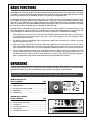
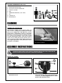
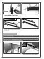
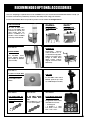
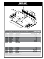
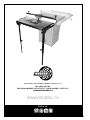
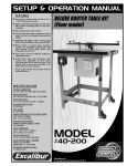
SETUP & OPERATION MANUAL CAST-IRON ROUTER EXTENSION KIT FOR TABLE SAWS FEATURES 16" x 27" cast-iron router extension table can be installed on 27”-29” table saws with cast-iron tables*. Includes self-adhesive mounting hole drilling guide/template for easy installation. Standard 9 1/4" x 11 3/4" router plate opening with phenolic router plate included. Two sturdy, flip-up, adjustable-length steel support legs. Deluxe 27” router fence has 2 1/4” dust collection outlet and adjustable scales. Kit Includes: 16" x 27" table (#40-070), set of two adjustable-length steel support legs (#40-068), deluxe router fence (#40-065) and 9 1/4" x 11 3/4" phenolic router insert plate (#40-114). * Depending on mounting location, some drilling or modifications may be required. SPECIFICATIONS • Table size 16" x 27" (902 x 686 mm) • Router plate size 9 1/4" x 11 3/4" • Fence size (each) 3" x 15 1/4" x 3/4" (76 x 387 x 19 mm) • Maximum fence travel 6" (152 mm) • Dust outlet 2 1/4" (57 mm) • Distance between t-slots & spindle center 3/4”: 5 1/16” (135 mm) 3/8”: 6 9/16” (167 mm) • Distance from spindle center to front edge of table 8" (205 mm) • T-slot dimensions 3/4” x 3/8” (19 x 10 mm) 3/8” x 1/4” (10 x 7 mm) • Table opening sizes (diameter) With insert ring: 1/2" (38 mm) Without insert ring: 3 3/4" (95 mm) MODEL # Version 1 - 29th January 2014 © Copyright General International 40-070EK GENERAL® INTERNATIONAL 8360 Champ-d’Eau, Montreal (Quebec) Canada H1P 1Y3 Telephone (514) 326-1161 • Fax (514) 326-5555 • www.general.ca THANK YOU for choosing this General® International model 40-070EK router table. This cast-iron table 40-070EK has been carefully tested and inspected before shipment and if properly used and maintained, will provide you with years of reliable service. For your safety, as well as to ensure optimum performance and trouble-free operation, and to get the most from your investment, please take the time to read this manual before assembling, installing and operating the unit. The manual’s purpose is to familiarize you with the safe operation, basic function, and features of this router table as well as the set-up, maintenance and identification of its parts and components. This manual is not intended as a substitute for formal woodworking instruction, nor to offer the user instruction in the craft of woodworking. If you are not sure about the safety of performing a certain operation or procedure, do not proceed until you can confirm, from knowledgeable and qualified sources, that it is safe to do so. Once you’ve read through these instructions, keep this manual handy for future reference. Disclaimer: The information and specifications in this manual pertain to the unit as it was supplied from the factory at the time of printing. Because we are committed to making constant improvements, General® International reserves the right to make changes to components, parts or features of this unit as deemed necessary, without prior notice and without obligation to install any such changes on previously delivered units. Reasonable care is taken at the factory to ensure that the specifications and information in this manual corresponds with that of the unit with which it was supplied. However, special orders and “after factory”modifications may render some or all information in this manual inapplicable to your machine. Further, as several generations of this model of router table and several versions of this manual may be in circulation, if you own an earlier or later version of this unit, this manual may not depict your unit exactly. If you have any doubts or questions contact your retailer or our support line with the model and serial number of your unit for clarification. GENERAL® INTERNATIONAL WARRANTY All component parts of General® International and Excalibur by General International® products are carefully inspected during all stages of production and each unit is thoroughly inspected upon completion of assembly. Limited Lifetime Warranty Because of our commitment to quality and customer satisfaction, General® International agrees to repair or replace any part or component which upon examination, proves to be defective in either workmanship or material to the original purchaser for the life of the tool. However, the Limited Lifetime Warranty does not cover any product used for professional or commercial production purposes nor for industrial or educational applications. Such cases are covered by our Standard 2-year Limited Warranty only. The Limited Lifetime Warranty is also subject to the “Conditions and Exceptions” as listed below. Standard 2-Year Limited Warranty All products not covered by our lifetime warranty including products used in commercial, industrial and educational applications are warranted for a period of 2 years (24 months) from the date of purchase. General® International agrees to repair or replace any part or component which upon examination, proves to be defective in either workmanship or material to the original purchaser during this 2-year warranty period, subject to the “conditions and exceptions” as listed below. To file a Claim To file a claim under our Standard 2-year Limited Warranty or under our Limited Lifetime Warranty, all defective parts, components or machinery must be returned freight or postage prepaid to General® International, or to a nearby distributor, repair center or other location designated by General® International. For further details call our service department at 1-888-949-1161 or your local distributor for assistance when filing your claim. Along with the return of the product being claimed for warranty, a copy of the original proof of purchase and a “letter of claim” must be included (a warranty claim form can also be used and can be obtained, upon request, from General® International or an authorized distributor) clearly stating the model and serial number of the unit (if applicable) and including an explanation of the complaint or presumed defect in material or workmanship. CONDITIONS AND EXCEPTIONS: This coverage is extended to the original purchaser only. Prior warranty registration is not required but documented proof of purchase i.e. a copy of original sales invoice or receipt showing the date and location of the purchase as well as the purchase price paid, must be provided at the time of claim. Warranty does not include failures, breakage or defects deemed after inspection by General® International to have been directly or indirectly caused by or resulting from; improper use, or lack of or improper maintenance, misuse or abuse, negligence, accidents, damage in handling or transport, or normal wear and tear of any generally considered consumable parts or components. Repairs made without the written consent of General® International will void all warranty. TABLE OF CONTENTS Rules for safe operation...................................................................................................... 5 Identification of main parts and components................................................................... 6 Basic functions ................................................................................................................... 7 Unpacking ....................................................................................................................... 7-9 List of contents................................................................................................................................................... 7-9 Cleaning............................................................................................................................. 9 Assembly instructions.................................................................................................... 9-19 Installing the router table support legs............................................................................................................. 9 Installing the router table.................................................................................................................................. 10 Assembly the router table and support legs.................................................................................................. 12 Installing the router fence................................................................................................................................. 13 Phenolic insert plate assembly........................................................................................................................ 15 Leveling and locking the router plate............................................................................................................. 16 Insert ring removal............................................................................................................................................. 17 Installing the starting pin................................................................................................................................... 17 Basic adjustments and controls....................................................................................... 17 Adjusting the fence along the rails................................................................................................................. 17 Adjusting the sliding scale on the rails............................................................................................................ 17 Adjusting the fence faces................................................................................................................................. 17 Operating Instructions................................................................................................. 18-19 Using the spacer bars for jointing.................................................................................................................... 18 Jointing................................................................................................................................................................ 18 Groove cutting................................................................................................................................................... 19 Profile cutting...................................................................................................................................................... 19 Recommended optionnal accessories............................................................................ 20 Parts list & diagrams.................................................................................................... 21-23 Contact information......................................................................................................... 24 RULES FOR SAFE OPERATION To help ensure safe operation, please take a moment to learn the machine’s applications and limitations, as well as potential hazards. General® International disclaims any real or implied warranty and hold itself harmless for any injury that may result from the improper use of it’s equipment. 1. Make sure that the operator has been properly trained and has read and understands the Owner’s Manual before operating any machinery. 2. Be sure to read, understand, and follow all instructions, warnings, and safety guidelines supplied with your table saw and router. 12. Keep all guards and safety devices in place and in good working order. If a guard must be removed for maintenance or cleaning make sure it is properly re-installed before using the machine again. 13. Hold the workpiece firmly against the table and use suitable support if the workpiece does not have a flat surface. 3. Keep the work area well lit, clean, and free of debris. 14. Feed the stock into the bit against the rotation direction of the bit. Never run the stock between the fence and the bit. 4. STAY ALERT! Give your work you undivided attention. Even a momentary distraction can lead to serious Do not operate the router with a damaged bit injury. 15. and/or the table saw with a damaged blade. 5. Do not wear loose clothing, gloves, bracelets, necklaces, or other jewelry. Wear protective hair cover- 16. Always disconnect the router and/or the table saw from the power source before changing acing to contain long hair and wear non-slip footcessories or before performing any maintenance wear. and adjustments or if the machine will be left unat tended. 6. Keep hands and other body parts well away from bits or cutting tools. When working close to the cutting tool, always use a feather board or push-stick 17. Be sure that all adjustment tools, wrenches, or other clutter are removed from the table surface and to hold or guide the workpiece. Do not clear chipsafelystored before sawing or routing. sand sawdust away with hands; use a brush. 7. Fine particulate dust is a carcinogen that can be hazardous to health. Always work in a well venti- 18. Make sure the router and/or table saw switch(es) is (are) in the “OFF” position before plugging in to a lated area and whenever possible use a dust colpower source. lector. 8. Be sure the router bit and/or saw blade has gained full operating speed before feeding the workpiece. 19. Avoid working from awkward or off-balance positions. Do not overreach and always keep both feet firmly on the floor. 9. Keep children and visitors at a safe distance when the table saw is in operation – do not permit them to operate the table saw. 20. Never leave the table saw and/or router unattended while running or with the power “ON”. 21. 10. Childproof and tamper-proof your shop and all machinery with locks, master electrical switches and switch keys, to prevent unauthorized or unsu22. pervised use. 11. Never stand or lean on your table saw. Serious injury can occur if the table saw is tipped or if unintentional contact is made with the spinning saw blade or router bit. Do not use this router extension wing/router fence for any purposes other than its intended use. If used for other purposes, General® International disclaims any real or implied warranty and holds itself harmless for any injury which may result from such use. 5 IDENTIFICATION OF MAIN PARTS AND COMPONENTS FRONT VIEW F D G E C A B H M L I J K A. CAST-IRON ROUTER TABLE H. 3/4” X 3/4” MITER T-SLOT (FOR MITER GAUGE) B. FENCE RAIL WITH SLIDING SCALE I. 3/8” MITER T-SLOT (FOR SHOP MADE JIGS) C. SLIDING ADJUSTABLE FENCE FACE J. SUPPORT LEG D. FENCE LOCKING HANDLE K. LEG ADJUSTMENT LOCK KNOB E. DUST SHIELD LOCK KNOB L. LEG SWIVEL LOCK KNOB F. DUST SHIELD M. PHENOLIC ROUTER INSERT PLATE G. FENCE BODY 6 BASIC FUNCTIONS The Excalibur by General International model 40-070EK Cast-Iron Router Extension Kit for Table Saws is designed to provide you with the full features and functionality of a stand-alone shop router table along with space-saving convenience and easy bolt-on installation directly to the end of your existing table saw. The 40-070EK is designed to either be fit onto the end of, or to replace one of the existing cast-iron extension wings on your table saw. Though 40-070 cast-iron table measures 27” the unit can also be installed centered on table saws with 28” or 29” tables with only a slight protrusion of the saw table beyond each end. To facilitate such installations, a self adhesive center-marked drilling template is included to allow you to locate and mark the mounting holes that may need to be drilled into your saw table or extension wing. Deciding whether to install the wing to the left or right of the saw is entirely a matter of personal preference, and will be determined by your own shop space considerations as well as the configuration, type, and model of saw you are installing it on. Whichever side you choose, here are a few factors to consider before installing: 1. Some cabinet saws have motor cover doors that extend underneath beyond the main table, this may prevent the router from being hung from that side of the saw, or may require lifting the router out of the table to allow opening the motor cover door. 2. The distance between the 40-070EK support legs and the cabinet door should also be verified to ensure adequate clearance for the door. 3. Table saw rip fence rails that go beyond the width of the table saw may cause obstructions at one or both ends, preventing installation of the router fence rails. Depending on your specific saw, the fence rails may need to be repositioned or shortened, or you may be obliged to install the 40-070EK on one specific end of the saw. 4. At least 3 of the pre-drilled mounting holes in the 40-070 should be used to secure it to the saw table. One near the front, middle, and rear. If mounting to the main table of your saw, drilling mounting holes into the lip of your saw table may not be required. However if mounting to the end of the saw’s extension wing, mounting holes will be required and an appropriate sized drill bit and mounting hardware are included. UNPACKING Carefully unpack and remove the components of the following 4 packages - that make up a complete Excalibur 40-070EK Router Table and check for damaged or missing items as per the list of contents below. TIP: PLEASE REPORT ANY DAMAGED OR MISSING ITEMS TO YOUR GENERAL® INTERNATIONAL DISTRIBUTOR IMMEDIATELY. INSERT PLATE (#40-114) LIST OF CONTENTS QTY A. ROUTER INSERT PLATE.................................................... 1 B. INSERT WRENCH............................................................ 1 D B E C A C. FLAT HEX SOCKET HEAD SCREW................................... 2 D. INSERT RING................................................................... 1 E. STARTING PIN................................................................. 1 SUPPORT LEGS (#40-068) LIST OF CONTENTS QTY A. SWIVEL LOCK KNOB................................................................. 2 B. LEG ADJUSTMENT LOCK KNOB............................................... 2 C. SUPPORT LEG............................................................................ 2 D. LEG MOUNTING BRACKET....................................................... 2 E. EXTENSION LEG........................................................................ 2 F. HARDWARE BAG/END CAPS.................................................... 1 A B D F E C 7 ROUTER FENCE (#40-065) LIST OF CONTENTS QTY A. DUST SHIELD................................................................... 1 A B C B. 1⁄4” DUST COLLECTION OUTLET..................................... 1 C. FENCE LOCKING HANDLE............................................ 2 D D. FENCE BODY.................................................................. 1 E. FENCE FACE................................................................... 2 F. FENCE SIDE RAIL W/SCALE........................................... 2 G. FENCE MOUNTING BRACKET........................................ 2 E H. SPACER BARS (FOR JOINTING WORK)......................... 2 I. LOCK KNOB................................................................... 8 J. T-BOLT (LONG)............................................................... 6 K. CAP SCREW................................................................... 6 F L. PLASTIC SPACER............................................................. 2 M. FLAT WASHER (SMALL)................................................. 14 N. T-BOLT (SHORT).............................................................. 2 O. PHILLIPS HEAD SCREW................................................... 2 P. HEX NUT (LARGE).......................................................... 2 Q. FLAT WASHER (LARGE).................................................. 2 R. SQUARE NUT.................................................................. 8 S. HEX HEAD BOLT............................................................. 6 N G H I R K S J L M O P Q CAST-IRON ROUTER TABLE (#40-070) LIST OF CONTENTS QTY A. CAST-IRON TABLE 16” X 27”...................................................... 1 B. FLAT HEAD CAP SCREW ......................................................... 10 C. HEX NUT.................................................................................. 10 D. FLAT WASHER............................................................................. 4 E. LOCK WASHER.......................................................................... 4 F. CAP SCREW ............................................................................. 4 G. HEX BOLT................................................................................... 3 H. FLAT WASHER............................................................................. 6 I. LOCK WASHER.......................................................................... 3 J. HEX NUT.................................................................................... 3 K. DRILL TEMPLATE AND DRILL BIT................................................ 1 A G B H C E F K 8 I D J ADDITIONAL REQUIREMENTS FOR SET UP A. B. C. D. E. F. G. H. PERSON FOR HELP WITH LIFTING A PHILLIPS AND FLAT HEAD SCREWDRIVERS ALLEN KEY (4 & 6 MM) B DRILL COMBINATION WRENCHES (8,10 & 16 MM) D F C G E PEN H 8 MM DRILL BIT MEASURING TAPE CLEANING CLEANING THE CAST-IRON TABLE The protective coating on the cast-iron table, prevents rust from forming during shipping and storage. Remove it by rubbing with a rag dipped in kerosene, mineral spirits or paint thinner. (Dispose of potentially flammable solventsoaked rags according to manufacturer’s safety recommendations). A putty knife, held flat to avoid scratching the surface, may also be used to scrape off the coating followed by clean-up with solvent. To prevent rust, apply a light coating of paste wax or use regular applications of any after-market surface protectant or rust inhibitor. TIP: WITH A SCREW DRIVER, PUSH A SOLVENT-SATURATED RAG INTO THE T-SLOTS TO REMOVE THE GREASE. ASSEMBLY INSTRUCTIONS ROUTING MAY PRESENT SERIOUS INJURY HAZARDS TO UNTRAINED USERS. BE SURE TO READ, UNDERSTAND AND FOLLOW ALL INSTRUCTIONS AND SAFETY RULES SUPPLIED WITH YOUR ROUTER. SUPPORT LEG ASSEMBLY I C D K E D 1. Screw the lock knob C into the weld-nut nut on the bracket D as shown. J K L M 2. Attach the leg mounting bracket E to the opposite end of the leg D as shown using the bolt, washer and lock nut. Note: Alignment pins K should point in same direction as bolt 9 H 3. Install the pivot lock knob with the bolt and the washer as shown. Note: the two lock knobs must be on the same side as shown in step 5. G 4. Insert the end cap into the end of the leg G (ignore the hole H). G C D 5. Insert the leg extension G to the leg D and tighten the lock knob C. Assemble the other leg following the same steps. 6. Assemble the other leg following the same steps. ATTACHING THE ROUTER TABLE TO THE SAW TIP: IF YOUR TABLE SAW MEASURES 27’’ SKIP STEP 2 & 3 AND SIMPLY STICK THE DRILL TEMPLATE TO THE VERTICAL EDGE OF YOUR SAW WITH THE ARROWS POINTING UP. TIP: IF YOU ARE ATTACHING THE ROUTER TABLE TO THE SAWS MAIN TABLE (TO REPLACE A REMOVED EXTENSION WING) STEPS 2 AND 3 WILL NOT BE NECESSARY. HOLD THE ROUTER TABLE UP AGAINST THE SAW’S MAIN TABLE AND LINE UP THE MOUNTING HOLES IN SAW WITH THE 3 CORRESPONDING PRE-DRILLED HOLES IN THE ROUTER EXTENSION AND PROCEED TO INSTALLATION STEP 8 AND 9 - BOLT AND LEVEL THE ROUTER TABLE TO THE MAIN TABLE. A 1. Clean the vertical edge of the table as shown. 10 2. If your saw measures more than 27”, measure and mark the midpoint of the saw table as shown, A. TIP: THREE MOUNTING HOLES WILL BE REQUIRED TO SECURE THE ROUTER TABLE TO THE SAW. THE CENTER HOLE AS WELL AS ONE HOLE AT EACH END OF THE TEMPLATE SHOW WHAT IS CONSIDERED TYPICAL HOLE PLACEMENT. B A 3. Peel the backing from the drilling template, line up the saw and template center marks and stick the template to the table with the arrows pointing up as shown. 4. Reach under the lip of the table to confirm that there is a flat surface for the nut and washer to rest on and that there is no cast ribbing in the drilling area, A. If no obstructions are found, drill the mounting holes starting with an 8mm (or smaller) pilot hole, B. Use the supplied 11mm bit to drill the holes to final size. NOTE: IF RIBBING OR OBSTRUCTIONS PREVENT DRILLING ANY OF THE HOLES, FOLLOW STEPS 5 & 6. IF NOT, PROCEED TO STEP 7. B CAST-IRON TABLE 27”X 16” #40-070 5. Set the router table down on the saw with the predrilled mounting holes facing you. Remove the drilling template from the saw and stick it as shown to the router table. From the pre-drilled holes in the router table, select and mark as shown B on the template the next closest hole to any holes that could not be drilled because of ribbing. 6. With the new hole location(s) marked on the drilling template, transfer the template back to the saw table and check behind the new hole locations for ribbing/obstructions. If obstructions are found again, repeat step 5. If no obstructions are found drill the mounting holes as described in step 4. TIP: FOR CONVENIENCE, IT IS RECOMMENDED TO INSTALL THE LEVELING SCREWS BEFORE INSTALLING THE TABLE. B C 7. Screw 10 leveling screws on the router table as shown. A 5 Note: The leveler screws need to be inserted from 6 the bottom as shown. The two outside holes are for the leveling screws C and the middle hole is used to 7 secure a plate, or the lift, to the table 11 TIP: STEPS 8 AND 9 REQUIRE THE ASSISTANCE TO HANDLE THE TABLE TOP FOR MOUNTING ON THE TABLE SAW. B A 8. Place the router table against the table saw and tighten the mounting screws B into the holes you drilled as shown A. 9. Use a straightedge to check the router table for level with the rest of the table. If needed, loosen the bolts slightly and make adjustments manually. In some cases shims between the router table and the saw may be required to level the tables. Simple shims made from small strips of aluminum foil can be used. INSTALLING THE ROUTER FENCE AND SUPPORT LEGS TIP: YOU HAVE TO START BY THE INSTALLATION GUIDE TWO RAILS TO PLACE THE SUPPORT LEGS. A B C C 1. Attach the two fence side rails with scale A to theirmounting brackets B, using 3 hex head bolts with flat washers and square nuts C, in the assembly order shown in D. 2. Attach the fence mounting brackets to the underside of the table, using 3 bolts C. K 3. Adjust the height of the 3 bolts in the slotted holes in the rail brackets so that the rails are leveled with the table as shown. 12 4. Place the leg bracket against the guide rail as shown. Note: The two pins K will help you for a perfect positioning. 5. Lock leg adjustment lock knob of the leg et lock the leg swivel lock knob to stabilize the positioning. 6. Drill two mounting holes of the leg as shown with a 11 mm bit and tighten the two mounting screws of the bracket with two 11 mm combination wrenches. A B 7. Insert an orange plastic spacer A with the short end down on one short T- bolt B, then insert the head of the bolt in the front upper slot in the fence body as shown. 8. Slide the 2 bolts and spacers to the middle of the fence body (approx.) A B C 9. Install the orange dust shield A on the two bolts and secure in place using two flat washers B and 2 lock knobs C as shown. 10.Secure the dust shield in place by tightening the two lock knobs. 13 B C A B 11. Insert a long T-bolt A through all 6 holes in the fence body B and, from the other side of the fence, loosely attach a flat washer C and lockknob B. Note: Do not tighten down the lock knobs, leave the T- head of the bolts protruding from the fence. 12. Slide the slot of one fence face onto the 3 elongat ed bolt heads. Tighten the lock knobs on the other side of the fence. C A A B 13. Tighten the 6 lock knobs A on the other side of the fence. 14. Insert a Phillips head screw A through both dust outlet mounting holes. Loosely thread a square nut B on both screws as shown C. A B B A 15.Insert the square nut in the fence body slot, A. Insert the other square nut in the slot on the other side of the fence, B. 16. Center the dust outlet with the hole in the fence body A, then tighten the two phillips head screws B. 14 A B C C 17.Insert a locking handle A with large flat washer C in the T-slot at one end of the fence, then from below, loosely thread a large hex nut B as shown. Note: Don’t forget the flat washer C. 18. Slide the hex nut in the fence rail as shown. Repeat steps 16 and 17 on the other end of the fence, then fully tighten the locking handle to lock the fence in position. INSTALLING A ROUTER SERIOUS PERSONAL INJURY COULD OCCUR IF YOU CONNECT THE MACHINE TO THE POWER SOURCE BEFORE YOU HAVE COMPLETED THE INSTALLATION AND ASSEMBLY STEPS. DO NOT CONNECT THE MACHINE TO THE POWER SOURCE UNTIL INSTRUCTED TO DO SO. 1. Make sure the router is off and disconnected from the power source. and install a 1/2 inch straight router bit into the routers collet, 2. Position the router on the underside of the plate with the router bit inserted through the hole in the insert ring, this will “centre the router”. 3. Scribe around the base of the router, locating where you will need to position the plastic base of your router to transfer your mounting hole locations to the plate. Note: You may need to position the router’s handles so that they will pass though the hole in the table top. Make a reference mark on the plate and the plastic base of your router to help relocate this position later in the installation. 15 4. Unscrew the plastic base as shown. 5. Remove the plastic base from your router. TIP: IF NECESSARY, RE-DRILL MOUNTING HOLES IN THE ROUTER BASE AND USE LONGER STRONGER FASTENERS (WE SUGGEST A FINE THREADAND NYLOCK NUTS) TO SECURE THE ROUTER TO THE INSERT PLATE. 7. Align the router base with the reference mark to the drawing on your insert plate, and transfer the router mounting hole locations to the insert plate. 8. Drill holes as shown. DO NOT MOUNT ROUTER UNLESS YOU ARE SURE IT IS SAFE TO USE. MAKE SURE THE ROUTER WILL NOT COME LOOSE FROM THE ROUTER PLATE. LEVELING AND LOCKING THE ROUTER PLATE A B C 1. Using a straightedge check that the router plate is level with the main table, A. Adjust the 10 leveling screws B in the table opening as needed to level the plate on all four sides. 2. With the router plate leveled to the table, lock the plate in place using the two supplied hex socket head screws C in the threaded holes on both sides of the plate. 16 INSTALLING THE STARTING PIN INSERT RING REMOVAL A B A 1. Insert the two pins of the wrench in the two holes on the insert ring then turn clockwise to unlock the ring, A and lift the insert ring up and out of the table insertion, B. 1. Install the starting pin A into the threaded hole on the router plate as shown. The starting pin can be used as needed for freehand or template routing only. BASIC ADJUSTMENTS & CONTROLS ADJUSTING THE FENCE ALONG THE RAILS ADJUSTING THE SLIDING SCALE ON THE RAILS B C D A The fence can be slid along the rails A. Loosen locking handles B, slide fence then lock in position by re-tightening the locking handle. Repeat on the other extremity of the fence. The scale on the rails can be adjusted along the rails C. Loosen lock knob D, slide the fence up to where you need it to be, then lock in position by re-tightening the lock knob. Repeat for the sliding scale on the other rail. ADJUSTING THE FENCE FACES C A B Depending on the size of the workpiece and the bit being used, the white fence faces can be adjusted along the fence body A. Loosen the 3 lock knobs, B on one side of the fence and then slide the fence face up to where you need it to be. Then lock in position by re-tightening the lock knobs. Repeat with the second fence face on the other side of the fence body. Note: Do not slide the fence faces too far and off the first T-bolt head, as shown in C. 17 OPERATING INSTRUCTIONS USING THE SPACER BARS FOR JOINTING A B 1. Jointing the edge of a board involves using a straight cutting router bit to remove material from the edge face of a board. The result is a perfectly flat and square edge. 2. Two spacer bars A are supplied with the fence system to facilitate jointing, by offsetting the outfeed fence B to the infeed fence and providing a straight path for the workpiece to follow as it is machined, fully supported at its start and end. 1,5 mm 0,7 mm Note: Both spacer bars should be used in the top and bottom t-slots in the fence body as shown. Take care to install them in matching offset positions; both at 0.7mm or both at 1.5mm. 3. Each spacer bar has two sides which allow you to offset the outfeed fence by either 0.7 mm or 1.5 mm staggering. Note: When not in use, the spacer bars can be stored on the t-track on the back of the fence body as shown. JOINTING A B 1. Loosen but do not remove the outfeed fence face and install the spacer bars between the outfeed fence and the fence body. With the router unplugged and the safety switch in the off position, follow the instructions supplied with your router and install a straight cutting bit in the router. 2. Adjust the height of the lift to raise or lower the bit as need until the bit is slightly higher than the workpiece. 3. Loosen the fence locking knobs, and using a straightedge, position the outfeed fence aligned flush with the bit, A. Rotate the bit by hand to validate alignment with the “highest” point of the cutting edge on the bit, then tighten the knobs to lock the fence in position. 4. Adjust the height of the safety shield to make sure it clears the bit and the workpiece slightly. 5. If needed, loosen the lock knobs on the back of the fence and adjust the faces to adjust the gap between the fence faces and the bit leaving a clearance of roughly 1/4” between the bit and each fence face, B. Plug in and turn on the router and make a test cut on a waste sample before jointing your “good” workpieces. 18 GROOVE CUTTING Note: Beading is commonly defined as cutting a groove or bead in the face of a board. 1. If installed, remove the spacer bars on the outfeed fence. 2. With the router unplugged and the safety switch in the off position, follow the instructions supplied with your router and install a cutting bit in the router. A 3. Raise or lower the router bit to the desired height. 4. Loosen the knobs and adjust the opening between the fences to allow the bit to clear the edge of bothfences. 5. Adjust the main fence until the center of the bit has reached the desired distance, A. 6. Align the infeed and outfeed fences parallel to eachother using a machinist square or a straightedge.. PROFILE CUTTING Profile cutting is usually performed using a bit with a guide bearing. The guide bearing controls the depth of cut into the edge face of a board. A good example would be a chamfer bit A. The bearing rides along the uncut edge of the board while the cutter removes the wood. 1. Follow steps 1 and 2 from previous section “ Groove Cutting ”. 2. Adjust the fence back and away from the bit only enough to allow the guide bearing to control the depth of cut or use the starting pin as a support for the work piece, as shown B. A B 3. Adjust the fence as close as possible to the bearing. The fence will serve as a backup support, reducing the chance of an accident. NOTES 19 RECOMMENDED OPTIONAL ACCESSORIES Here is a sampling of optional accessories available from your local General International dealer to help you increase convenience, productivity, accuracy and safety when using your machine. For more information about our products, please visit our website at www.general.ca Item #40-175 HORIZONTAL FEATHERBOARD For Excalibur router table. DUST COLLECTOR We offer a wide selection of top quality dust collectors to suit all your shop needs. Dust collectors contribute to a cleaner more healthful workshop environment. Item #40-120 Item #40-125 ROUTER LIFT STOCK PUSHER Heavy-duty massive router lift with 9 ¼" x 11 ¾" aluminum top plate. Stable 4 post/lift screw design & chain drive lifting system controlling all 4 corners simultaneously. For Excalibur router fence #40-065 (bench top model) & #40-080 (floor model). Item #40-115 Item #40-090 9 1/4” X 11 3/4” ALUMINUM INSERT PLATE FLIP STOP For Excalibur router tables. For Excalibur router fence #40-065 (bench top model) & #40-080 (floor model). Item #40-076 Item #40-074 Item #40-099 4 PC INSERT RING SET 1⁄4”, 1⁄2”, 2 1⁄2” & 1 3/8” (30 MM FOR #40-099) 4 PC ZERO CLEARANCE INSERT RING SET For Excalibur 9 1/4” x 11 3/4” router plates 9 PCS BRASS PRECISION TEMPLATE GUIDE SET Item #40-160 VERTICAL FEATHERBOARD For Excalibur router table. Designed for most routers. Included accessories: • 1 locking nut • 8 guides: 1 1 19⁄64”, 5/8”, 27⁄32”, 17⁄32”, 17⁄64”, 9⁄32”,11⁄32”, 13⁄32”. 20 PARTS LIST Support legs (#40-068) (Left Side) 12 13 (Right Side) 1 3 1 13 14 15 15 12 3 14 13 2 2 7 13 5 7 5 2 6 2 6 4 4 5 5 8 8 9 9 10 10 11 11 IMPORTANT: When ordering replacement parts, always give the model number, serial number of the machine and part number. Also a brief description of each item and quantity desired. PART # REFERENCE # DESCRIPTION SPECIFICATION QTY 1 2 3 4 5 6 7 8 9 10 11 12 13 14 15 27160070 917M04010 904M08050 27160071 9145161802 912M08000 909M08050 939M08000 940M08020 27160072 27160073 904M06020 914M061301 915M06000 910M06000 LEG BRACKET LOCK PIN M4 X 10 MM HEX BOLT M8 X 50 MM LEG 30 X 30 X 500 MM FLAT WASHER M8 NYLOCK NUT M8 CARRIAGE BOLT M8 X 50 MM LOCK KNOB M8 LOCK KNOB M8 X 20 MM LEG 25 X 25 X 500 MM TUBE PLUG HEX BOLT M6 X 20 MM FLAT WASHER M6 LOCK WASHER M6 HEX NUT M6 2 4 2 2 4 2 2 2 2 2 2 4 8 4 4 21 PARTS LIST CAST-IRON TABLECast-iron 27”Xtable 16” (#40-070) #40-070 1 8 10 9 3 2 4 5 6 13 7 11 10 12 IMPORTANT: When ordering replacement parts, always give the model number, serial number of the machine and part number. Also a brief description of each item and quantity desired. PART # REFERENCE # DESCRIPTION SPECIFICATION QTY 40070-01 40075-02 40075-03 40075-04 40075-05 40075-06 40075-07 40070-08 40070-09 40070-10 40070-11 40070-12 40070-13 2716U014 903M06030 910M06000 905M06020 914M061602 915M06000 901M06016 T2716020 904M10035 9014382503 915M10000 910M10008 953M11000A CAST-IRON TABLE 16” X 27” FLAT HEAD CAP SCREW M6 X 30 MM HEX NUT M6 FLAT HEAD SCREW M6 X 20 MM FLAT WASHER M6 LOCK WASHER M6 CAP SCREW M6 X 16 MM DRILLING TEMPLATE HEX BOLT M10 X 35 MM FLAT WASHER M10 LOCK WASHER M10 HEX NUT M10 DRILL BIT Ø11 1 2 10 10 6 6 6 1 3 6 3 3 1 22 PARTS LIST Router fence(#40-065) 2 5 9 6 3 33 17 8 35 32 35 14 13 15 33 16 7 4 4 2 16 11 5 34 4 19 12 17 17 6 16 18 1 8 10 6 17 7 35 35 9 12 13 15 14 18 16 20 17 19 IMPORTANT: When ordering replacement parts, always give the model number, serial number of the machine and part number. Also a brief description of each item and quantity desired. PART # REFERENCE # DESCRIPTION SPECIFICATION QTY 4006501 40080-02 40065-03 40080-04 40080-05 40080-06 40080-07 40080-08 40065-09 40080-10 40065-11 40065-12 40065-13 40065-14 40065-15 40080-16 40080-17 40080-18 40080-19 40080-20 40080-32 40080-33 40080-34 40080-35 27160032A 60100001A T2716002 32240052A 9145162302 939M08000B 32240034 27160035A 27160036 32240037 32240038 27160039 27160040 27160041 T2716003 935014000 9140141602 901M06012 904014058 940M06012 32240013A 906014034 32240033A 32240060 FENCE BODY 780 MM LOCK HANDLE 5/16” SCALE 780 MM T-BOLT FLAT WASHER M8 LOCK KNOB M8 LOCK NUT M8 H SPACER 388 MM FENCE FACES 388 MM SAFETY GUARD FENCE SPACER SIDE BRACKET BASE 240 MM SIDE BRACKET 280 MM RULE PLATE 205 MM SCALE 205 MM SQUARE NUT 1/4" FLAT WASHER M6 CAP SCREW M6 X 12 MM HEX BOLT 1/4" X 5/8” LOCK KNOB M6 X 12 MM DUST PORT PHILLIPS HEAD SCREW 1/4" X 3/4" T-BOLT FLUOROWAY PAD 1 2 1 6 2 8 2 2 2 1 2 2 2 2 2 8 14 8 6 2 1 2 2 1 23 8360 CHAMP-D’EAU, MONTREAL (QUEBEC) CANADA H1P 1Y3 TEL.: (514) 326-1161 FAX: (514) 326-5565 - PARTS & SERVICE / (514) 326-5555 - ORDER DESK [email protected] WWW.GENERAL.CA Follow us: 24