1
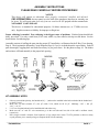
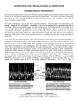
CONSTRUCTION & INSTALLATION EXPANDER 240 ELECTRONIC CRYSTAL SWITCH INTRODUCTION The EXPANDER 240 is a compact crystal switch which allows up to six synthesizer mixing crystals to be remotely selected. Its purpose is to provide new injection signals for loop mixing in PLL synthesizer circuits, or additional mixing frequencies for older 23-channel type CBs using crystal synthesizers. Each crystal position includes a series trimmer capacitor for exact frequency adjustment if needed. The appropriate mixing crystal is removed from the radio, and installed in the EXPANDER 240 PC board instead. Two wires from the EXPANDER 240 are installed in the empty crystal hole in place of the removed crystal. Crystal selection is made electronically through diodes. This eliminates the problem of stray wire capacitance often occurring in mechanical switching devices. Because of this advantage, the crystal PC board can be placed physically close to the required circuit, while the switching wires can be made long enough to reach the actual switch mounted elsewhere on the chassis. (Often a relatively long distance from the PC board.) Generally speaking, any PLL type radio using a loop mixing frequency can be expanded by 40 channels per mixing crystal (or 23 channels per crystal, in some early PLL circuits), up to the limit of the CB’s tuning circuits. Thus a typical American 40-channel CB can be made to work on 80, 120, or even 160 total consecutive channels in some cases. For the older 23-channel crystal-synthesized radios, the extra coverage will be 20 channels, for a total of 43 consecutive channels. CIRCUIT DESCRIPTION The electrical operation is very simple. Refer to the Schematic Diagram, Page 9. Wires from holes “A” and “B” are connected in place of the crystal that was removed from the radio. A regulated DC voltage of +7-10 VDC from the radio is applied through the user’s switch. The associated diode (D1-D6) will find a path to ground via R1 and L7 and conduct. R1 and L7 are common to all switching diodes and are used for RF isolation. In addition each diode is further decoupled by C1-C6 and L1-L6. When the diode conducts, there will be RF continuity from hole “B” through C7, the associated diode, the series capacitor CT1-CT6, the crystal, and finally to hole “A.” NOTE: Either a series capacitor or a bare jumper wire must be installed in the holes marked “CT1-CT6.” Otherwise there would be no RF continuity to ground, and the circuit wouldn’t oscillate. Since the trimmer capacitors are the most expensive parts in this kit, and since few American CBs can cover more than 120 channels anyway, only three trimmers are provided. They often aren’t even needed, and in most cases a bare jumper wire will work. If a crystal does need trimming, try a fixed ceramic disc capacitor of about 10-68 pF in these holes first. (Extra trimmers are available from us at $1 each.) Copyright 1985–2002 by L.M. Franklin. All rights reserved Published by: CBC INTERNATIONAL • P.O. BOX 30655 • TUCSON AZ 85751 U.S.A. TEL/FAX: 888-I-FIX-CBs (1-888-434-9227), (520) 298-7980 Internet: www.cbcintl.com • Email: [email protected] ASSEMBLY INSTRUCTIONS PLEASE READ CAREFULLY BEFORE PROCEEDING! NOTICE This device will operate as advertised when properly constructed, installed, and adjusted. CBC INTERNATIONAL has no control over the skill of the purchaser; therefore no warranty can be given. We will repair units built only from our own kits for $25 prepaid with the returned unit. NO BASKET CASES PLEASE! This device is intended for educational purposes, 10-Meter Amateur use, or 27 MHz receivers only. Supplier assumes no liability for improper or illegal use. Proper soldering is essential. Poor soldering is the biggest cause of problems. Finished joints should look shiny, never dull. Use only a small iron (25-45 watt) with a very fine round or slot tip to avoid shorts. See the sketch below for soldering tips. Assembly consists of stuffing the parts into the proper PC board holes, as illustrated in the X-Ray View drawing, Page 8. Check against the Schematic Circuit Diagram (Page 9) if you’re in doubt about the correct holes. Push all parts down tight, wiggling back and forth if necessary as you press down. See the photo on Page 10. The diodes and resistors will bend naturally to the proper hole spacing. KIT ASSEMBLY NOTES 1. 2. 3. 4. 5. Observe correct diode polarity; the banded end is [—] and must be installed in the holes marked with the banded end on the PC board. Make sure you don’t mistake C7 (.001 µF) with C1-C6, which are all .01 µF. Markings: “102” = .001 µF, “103” = .01 µF. L1-L7 are not polarized and can be installed with leads either way. Make sure the “A” and “B” wire connections go to the cold side and hot side of the radio’s oscillator circuit, respectively. Don’t forget to install a trimmer, fixed capacitor, or bare jumper wire in the CT1-CT6 positions (or however many crystal positions you’re actually using) to complete the RF circuit continuity. ___________________________________________________________________________________________________ EXPANDER 240 PAGE 2 CRYSTAL ORDERING The following specifications should be observed when ordering crystals. to start, say, exactly 2 MHz higher (28.965 MHz), just add 2 MHz to a direct loop crystal, 1/3 of 2 MHz (667 KHz) to a tripler crystal, or 1/2 of 2 MHz (1 MHz) to a doubler crystal. Refer to the later examples, which should clarify this idea. FREQUENCY: ACCURACY: HOLDER TYPE: CRYSTAL SUPPLIERS CRYSTAL CUT: LOAD CAPACITANCE: As desired. .005% or better. HC18/U or HC49/U with solder leads. Fundamental up to about 20 MHz. Crystals which are being multiplied in the radio should be specified as such. (For example, the 11.325 MHz crystal used in the Cobra 148/2000GTL chassis is a tripler cut type.) 10 pF (series) preferred for easy adjustment. The 32 pF used in many CB oscillators can be hard to net by the trimmer alone. If you already have crystals with different specs, they can be tried first and will usually work. If you have the plug-in HC25/U types, these can also be used by drilling out the PC board holes to fit their thicker pins. The PC foil pads have purposely been made extra large for this reason. The drill size would be 0.052." Solder the pins directly to the PCB; using a crystal socket adds extra shunt capacitance. CRYSTEK CORP. 2351/2371 Crystal Dr. Ft. Myers FL 33907 TEL: (800) 237-3061, (941) 936-2109 FAX: (941) 939-4226 www.crystek.com INTERNATIONAL CRYSTAL MFG. 10 N. Lee Av., P.O. Box 26330 Oklahoma City OK 73102 TEL: (800) 426-9825, (405) 236-3741 FAX: (405) 235-1904 www.icmfg.com JAN CRYSTALS 2341 Crystal Dr. Ft. Myers FL 33907 TEL: (800) 526-9825, (941) 936-2397 FAX: (941) 936-3750 HOW TO FIGURE YOUR NEW CRYSTAL FREQUENCIES PARTS SUPPLIERS The effect of the EXPANDER 240 in a PLL circuit is always the same: the new injection signals simply drive the VCO up or down as required, until the input to the PLL’s Programmable Divider is correct and the loop locks. (This assumes the radio has not been modified by binary code changes, or has otherwise been returned to its stock circuit configuration before installation.) Figuring new crystal frequencies is therefore a matter of adding or subtracting the desired amount of up or down shift, respectively, to the output side of the PLL’s Mixer stage. CIRCUIT SPECIALISTS INC. 220 S. Country Club Dr. #2 Mesa AZ 85210 TEL: (800) 528-1417, (480) 464-2485 FAX: (480) 464-5824 www.web-tronics.com The 40-channel CB band has a total bandspread of 440 KHz (27.405 MHz - 26.965 MHz = 440 KHz); the older 23-channel PLL radios have a bandspread of 290 KHz (27.255 MHz - 26.965 MHz = 290 KHz.) For continuous expanded range, each new crystal must add or subtract 450 KHz or 300 KHz respectively, to the preceding crystal. When the oscillator signal is used directly without multiplication, add or subtract the 450/300 KHz directly to each succeeding crystal. If the crystal is one that’s being doubled or tripled, add 1/2 or 1/3 of the 450/300 KHz respectively, to each succeeding crystal. DIGIKEY CORP. 701 Brooks Av. South P.O. Box 677 Thief River Falls MN 56701. TEL: (800) 344-4539, (218) 681-6674 FAX: (218) 681-3380 www.digikey.com MOUSER ELECTRONICS 1000 N. Main St. Mansfield TX 76063 TEL: (800) 346-6873, (817) 804-3888 www.mouser.com The same principle applies to 10-Meter Amateur conversions. If you want the Channel 1 operating frequency ___________________________________________________________________________________________________ EXPANDER 240 PAGE 3 INSTALLATION NOTE: The radio’s tuned circuits may need realignment after installation of the EXPANDER 240. Much depends upon the desired center operating frequency of the expanded radio. Therefore a schematic diagram of the radio is essential, as well as an accurate Frequency Counter. Although specific installation points are described for some popular models, the work should be done by a qualified electronic technician. The supplier assumes no liability for damage to any equipment resulting from improper installation. TYPE 1 INSTALLATION — All 23-Channel AM or AM/SSB Crystal-Synthesized Radios See FIGURE 1. These radios all use banks of crystals that mix together, most often in the 6-4-4 or 6-4-2 configurations. The most common AM schemes use the 37 MHz plus separate 10 MHz banks each for RX and TX (FIGURE 1-A), or the 23 MHz/14 MHz plus separate 11 MHz RX and TX Local Oscillators (FIGURE 1-B). AM/SSB radios generally use crystals in the 7.8 MHz or 11 MHz range for this bank. Note that the SSB types also have crystals in the Carrier Oscillator and synthesizer stages to provide the SSB mode offsets. But these crystals will have no effect on the location of the EXPANDER 240. Refer to FIGURE 1 on the next page for the general connection points. Remember, you must check the radio’s schematic for the exact location. The “Xs” show where you’ll be breaking the existing signal path to inject your own new mixing frequencies. In all cases, make sure you install the EXPANDER 240 wires coming from its “A” and “B” holes to the correct empty PC foils left by the crystal you removed from the radio: “A” is the cold or ground side, and “B” is the hot side of the oscillator. The crystals to be added will go in the bank containing the six mixing crystals, regardless of whether the radio is AM or AM/SSB. These six crystals always mix to control the following six continuous channel groups: Mount the EXPANDER 240 as physically close to the radio’s crystal as possible to avoid problems with long leads from the “A” and “B” hole wires. Then you can run the ribbon cable any convenient length to where you’ve actually mounted your hard switch. The “GND” symbol hole above the “6” hole on the PC board must be tied to the chassis common point of the radio to avoid ground loops. This radio ground point is the same one used for, among other things, the metal shield cans on the tuning transformers. You can solder the BLACK wire to the nearest metal tuning coil using the shortest wire length possible. Connect the RED wire through your switch pole common to a constant regulated DC source of +7-10 VDC; all CBs will have at least one of these available somewhere in the power supply distribution chain. Remove one of the six crystals from the radio and place it in the “X1” crystal position of the EXPANDER 240 instead. To make it easy to remember which Channel Selector positions provide which new channels, you should remove either the lowest or the highest frequency mixing crystal, depending upon whether you are expanding the radio below Ch. 1 or above Ch. 23. Observe the correct hot and cold crystal connections, as noted above. GENERAL INSTALLATION BY CHASSIS TYPE Radios to be expanded can be classified into three general categories: TYPE 1: TYPE 2: TYPE 3 All crystal-synthesized 23-channel AM or AM/SSB models. All AM or AM/SSB PLL types having a crystal oscillator loop mixing stage which is doubled or tripled by subsequent tuned circuits. All AM or AM/SSB PLL types having a fixed crystal oscillator loop mixing stage operating directly at the crystal frequency. Channels 1, 2, 3, 4 Channels 5, 6, 7, 8 Channels 9, 10, 11, 12 Channels 13, 14, 15, 16 Channels 17, 18, 19, 20 Channels 21, 22, 23 For 10-Meter conversions there are two possibilities. You’ll either remove the highest radio crystal and add the five extras, or you’ll replace all six in addition to those in the EXPANDER 240, for a total of 43 consecutive channels. Install your new crystals in the remaining #2-#5 positions of the EXPANDER 240. Put them in the correct order (#2, #3, #4, #5, #6) so that your chosen switch makes the frequency bands continuous. Since you’re adding up to five extra crystals, and each one will be mixed in the radio with four others, this means you will get a total of twenty additional new channels. Using a 12" piece of hookup wire (provided in our kits); cut it in half and place the two pieces in the “A” and “B” holes of the EXPANDER 240. Install the two loose wire ends from holes “A” and “B” in the two now-empty holes where you removed the mixing crystal, being sure to put the “A” wire in the low or ground side hole, and the “B” wire in the hot or oscillator side hole of the radio. ___________________________________________________________________________________________________ EXPANDER 240 PAGE 4 EXAMPLE A: Cobra 29 AM chassis. This uses the standard 23 MHz and 14 MHz mixers, with the 11.730 MHz RX and 11.275 MHz TX oscillators. There are six 23 MHz crystals, and these are the ones to change. (TYPE 1-B.) Note that they change in 50 KHz steps: 23.290, 23.340, 23.390. 23.440, 23.490, 23.540. The next three for continuous lower frequencies would be 23.240, 23.190, and 23.140 KHz.. This gives twelve continuous lower channels from 26.955 MHz downward in the Ch. 1-4 positions, four channels for each of the three new crystals plus the original 23.290 MHz. EXAMPLE B: Cobra 134/138/139 and Midland 13-895 AM/SSB Uniden chassis. This uses 8 MHz and 11 MHz mixing banks, with a 7.8 MHz Carrier Oscillator. The 8 MHz are the ones to change, since there are six of them. Once again, they change in 50 KHz steps: 8.1590, 8.2090, 8.2590, 8.3090, 8.3590, and 8.4090 MHz. The next three for continuous higher frequencies would be 8.4590, 8.5090, and 8.5590 MHz. This gives you the next twelve higher frequencies starting at 27.265 MHz in the Ch. 1-4 positions, four channels for each of the three new crystals plus the original 8.4090 MHz. For 10-Meter use, add the desired up-shift directly to the highest radio crystal, 8.4090 MHz. NOTE: These old CBs will never cover both the 10M and 11M bands without retuning. You could get a straight 23 channels on 10M by just replacing the existing six crystals, without even using the EXPANDER 240. Using it, you’d get 23 channels plus 20 channels more, for a total of 43 channels on 10M. This assumes you’re willing to buy a total of twelve new crystals, six to replace the radio’s ___________________________________________________________________________________________________ EXPANDER 240 PAGE 5 originals, plus six to fit in the EXPANDER 240. Obviously, you could choose anything from 20-43 channels, depending upon how much you’re willing to spend on new crystals. use 11.5575 MHz (28.300 to 28.740 MHz) or 11.4575 MHz (28.000 to 28.440 MHz) depending upon your need for the USB or CW/USB parts of the band. TYPE 2 INSTALLATION — All PLL AM or AM/SSB with Oscillator Doubler or Tripler Stages EXAMPLE B: Cobra 148/2000GTL, new Uniden GRANT or MADISON chassis. The existing crystal is a tripler, 11.325 MHz. New crystals would be 11.175 for the lower 40, 11.475 for the high 40, and 11.625 MHz for the high-high 40 channels. For 10M, use 11.770 or 11.670 for USB or CW/USB; same coverage as above. In these radios, the crystal oscillator is doubled or tripled in frequency to get close to the output frequency of the VCO, which is typically operating in the 33-38 MHz range. The multiplier stage can’t be bypassed for two reasons: 1. The SSB versions will have USB/LSB offset tuning adjustments following the multiplier stage. 2. There is usually a Delta-Tune (AM-only rigs) or Clarifier (AM/SSB rigs) circuit on the low side of the crystal, which must be retained for proper operation. See FIGURE 1, TYPE 2. Remove the radio’s loop mixing crystal, and install it in the EXPANDER 240 along with your new crystals. The signal at point “B” now depends upon which external mixing crystal you select. Remember to use the correct crystal positions that match your desired switching order. Install two short hookup wires in the EXPANDER 240’s “A” and “B” holes. Place the other wire ends in the corresponding high side (“B”) and low side (“A”) holes where you removed the radio’s crystal. The net effect is that you now have several loop mixing crystals in series between the Delta Tune/Clarifier (low crystal side) and the oscillator (high crystal side) circuit points. For the SSB radios in particular, it’s very important to adjust all crystals for the proper frequency. Make all adjustments in the “AM” mode. There should be enough range with the trimmers for exact netting. You should then check the USB/LSB offsets. These are usually ±1.5-2.5 KHz, as measured at the output of the tuned circuit which does the multiplication. Adjust the offsets according to the radio service manual, using the standard FCC band, Clarifier at its midrange. When switching to the new crystals, the existing offset adjustments should shift them by about the same amount. The Cybernet PLL02A SSB chassis uses trimmer capacitors for the offsets, while the Uniden SSB chassis types use coils to set the offsets. NOTE: The 11.325 crystal used in some older Cobra chassis is the oversize HC/33 type, not the standard HC/18 case. For CB expansion you’ll also have to replace that one, since the HC/33 type won’t fit in the EXPANDER 240 PC board. EXAMPLE C: Cybernet PLL02A U.S. SSB chassis (Telsat SSB140, JC Penney 6247, etc.). The existing crystal is 10.0525 MHz and is doubled. New crystals would be 9.94 MHz for the low 40, 10.165 MHz for the high 40, and 10.2775 MHz for the high-high 40. On 10M, you can use 10.38625 for USB, or 10.31125 MHz for CW/USB. EXAMPLE D: Early generation Cybernet PLL02A AM chassis with the 11.8066 MHz crystal. (Midland 13-857B, 13-882C, G.E. 3-5810B, Kraco KCB2320B, etc.) This crystal is being tripled. New crystals could be 11.6567 MHz for the low 40, and 11.9567 MHz for the high 40 channels. EXAMPLE E: Cobra 138/139XLR Uniden SSB chassis. These models use three separate 11 MHz tripler crystals for loop mixing. Therefore you can’t use the EXPANDER 240 for CB expansions because you’d need three of them. However for 10-Meter Novice use you only need USB, and could change just that mode’s crystal. Replacing the existing 11.2858 MHz USB crystal with one of 11.7308 MHz would give you 28.300 MHz to 28.740 MHz. There are many other American SSB chassis that use separate AM/LSB/USB mode crystals, and the same principle would apply. A few examples are the JC Penney 981-6246 and 981-6248, Realistic TRC448, Sears 934.3826, 934.3827, and 934.3831, and Wards GEN719A. EXAMPLE A: Cobra 140/142GTL Uniden chassis. This uses an 11.1125 MHz tripler crystal. New crystals might be 10.9625 for the lower 40, 11.2625 for the high 40, and 11.4125 MHz for the high-high 40 channels. For 10 Meters, ___________________________________________________________________________________________________ EXPANDER 240 PAGE 6 TYPE 3 INSTALLATION — All PLL AM or AM/SSB with Direct Frequency Mixing See FIGURE 1, TYPE 3. The oscillator output is coupled through a small disc capacitor or tuning coil to the Mixer stage. Remove the oscillator crystal, and place the “A” and “B” wires of the EXPANDER 240 in those empty holes. EXAMPLE A: Any AM Courier model with the REC86345 PLL chip. The mixer crystal is 36.380 MHz. New crystals might be 35.930 MHz for the lower 40, and 36.830 MHz for the upper 40 channels. These are tripler cut (Third Overtone) type crystals. NOTE: Many other AM-only PLL radios also use the 36 MHz circuit. Included are those models with the SM5104, TC5080, µPD858, and µPD861 chips, and the Royce “sardine can” modular AM models. The same method works in all these as well. EXAMPLE B: Cobra 29/89XLR Uniden chassis with µPD858 PLL chip. IN CASE OF DIFFICULTY Recheck soldering and parts placements. Use a strong backlight against the PC board to look for solder bridges and shorts. Check for proper diode polarity mounting. Use a ’scope, RF voltmeter or Frequency Counter to see if radio oscillator is running with EXPANDER 240 installed. Verify that the EXPANDER 240 is in fact being powered by DC; the common “GND” hole in the PC board must be tied to the radio’s common foil via the BLACK wire, and the RED wire to your switch common pole. If it’s getting power, the cathode of the diode that’s currently being switched will measure about 0.6 VDC less than its anode supply. If you expect your kit to work properly, try very hard to install the parts neatly and correctly, as shown in the X-Ray View and the photograph on Page 8 and Page 10. Press all parts down tight against the PC board; rock the diode or resistor leads back and forth while pressing, until they fit flush against the PC board. For specific information about models not included here, send a large self-addressed stamped envelope or an email, and the exact radio make and model. We do not sell schematics or SAMS Fotofacts, so please don’t ask. If you don’t have a schematic or don’t understand exactly what to do, don’t touch! Leave it to professionals. Replace the existing 36.57 MHz crystal. New crystals would be 36.12 MHz for the lower 40, and 37.02 MHz for the upper 40. These are also Third Overtone cuts. Telephone to order SAMS CB Fotofacts: (800) 428-7267, (317) 298-5400 EXAMPLE C: Realistic TRC459/TRC480 Because the LC7113 PLL chip is now extinct and this chassis was very expensive, it’s worth saving and expanding. The loop crystal is 17.8875 MHz. New crystals might be 17.4375 MHz for the lower 40, and 18.3375 MHz for the upper 40 channels. For 10M, use 18.4825 MHz CW/USB or 18.7825 MHz USB only. Internet: www.samswebsite.com/photofacts.html ___________________________________________________________________________________________________ EXPANDER 240 PAGE 7 C1-C6 C7 D1-D6 L1-L7 R1 CT1-CT6 = = = = = = .01 µF ceramic disc capacitor (Radio Shack #272-131 or #272-1065) .001 µF ceramic disc capacitor (Radio Shack #272-126) 1N914 type fast switching diode (1N4148, ECG519, Radio Shack #276-1122) 470 µH RF choke (Mouser or Circuit Specialists #43LS474) 1KΩ, ¼-watt resistor (brown-black-red, Radio Shack #271-1321) 9-50 pF plastic or ceramic trimmer capacitor, micro-miniature 5mm size. (Mouser/Circuit Specialists #ME242-8050 or #24AA024) NOTE: Any fixed ceramic capacitor of about 10-68 pF can be also used at CT1-CT6 to trim exact crystal frequency. You can even use a bare jumper wire if no trimming is needed. But you must install something in these holes to complete the RF continuity to ground; otherwise the circuit won’t oscillate! Miscellaneous: 1 each, EXPANDER 240 printed circuit board. Crystals and switch per your requirements. (See text.) Most parts are available from Radio Shack except for the trimmers and RF chokes. See Page 3 for addresses of other suppliers. A complete kit is available for $28 including shipping from: CBC INTERNATIONAL, P.O. BOX 30655, TUCSON AZ 85751 U.S.A. ___________________________________________________________________________________________________ EXPANDER 240 PAGE 8 ___________________________________________________________________________________________________ EXPANDER 240 PAGE 9 ___________________________________________________________________________________________________ EXPANDER 240 PAGE 10