1
Command Reference
Digi Connect® Family
Digi Connect SP, Digi Connect Wi-SP, Digi Connect ME, Digi Connect Wi-ME, Digi Connect EM, Digi Connect Wi-EM,
Digi Connect WAN, Digi Connect RG, Digi Connect ES Family
www.digi.com
90000566_D
Digi International Inc. 2003, 2004, 2005. All Rights Reserved.
Digi, Digi International, the Digi logo, the Digi Connectware logo, the Making Device Networking Easy logo,
Digi Connect Family, Digi Connect SP, Digi Connect Wi-SP, Digi Connect ME, Digi Connect Wi-ME, Digi Connect EM,
Digi Connect Wi-EM, Digi Connect WAN, Digi Connect RG, and Digi Connect ES are trademarks or registered trademarks
of Digi International, Inc. in the United States and other countries worldwide. All other trademarks are the property of their
respective owners.
Chapter 1 Introduction
Quick Reference for Configuring Features ............................................ 6
Basic Command Information ................................................................. 9
Access the Command Line.................................................................. 11
Configure an IP Address ..................................................................... 11
Chapter 2 Command Descriptions
Verifying Device Support for Commands ............................................ 13
backup ................................................................................................. 14
boot...................................................................................................... 15
close .................................................................................................... 17
connect ................................................................................................18
display ................................................................................................. 19
display buffers ..................................................................................... 21
exit ....................................................................................................... 23
help...................................................................................................... 24
info....................................................................................................... 25
kill ........................................................................................................ 33
mode.................................................................................................... 34
newpass .............................................................................................. 35
ping...................................................................................................... 36
quit....................................................................................................... 37
reconnect............................................................................................. 38
revert ................................................................................................... 39
rlogin.................................................................................................... 42
send.....................................................................................................43
set accesscontrol................................................................................. 44
set alarm.............................................................................................. 46
set autoconnect ................................................................................... 51
set buffer.............................................................................................. 55
set devicesecurity ................................................................................ 57
set ethernet.......................................................................................... 60
set forwarding ...................................................................................... 62
set gpio ................................................................................................63
set group.............................................................................................. 65
set host ................................................................................................68
set menu.............................................................................................. 69
set mgmtconnection ............................................................................ 74
set mgmtglobal .................................................................................... 77
set mgmtnetwork ................................................................................. 78
set nat.................................................................................................. 81
set network .......................................................................................... 84
Contents
3
set permissions.................................................................................... 86
set pmodem....................................................................................... 102
set pppoutbound................................................................................104
set profile ........................................................................................... 110
set rciserial ........................................................................................ 113
set rtstoggle ....................................................................................... 114
set serial ............................................................................................ 116
set service ......................................................................................... 118
set snmp ............................................................................................ 120
set system ......................................................................................... 122
set tcpserial ....................................................................................... 123
set term..............................................................................................126
set udpserial ...................................................................................... 127
set user..............................................................................................131
set wlan ............................................................................................. 136
show .................................................................................................. 144
status ................................................................................................. 147
telnet.................................................................................................. 148
who .................................................................................................... 149
Chapter 3 Modem Emulation Commands
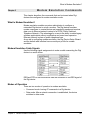
What Is Modem Emulation? .............................................................. 151
Modem Emulation Cable Signals ...................................................... 151
Modes of Operation ........................................................................... 151
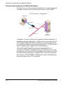
Common User Scenarios for Modem Emulation ............................... 152
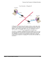
Connection Scenarios for Modem Emulation .................................... 154
About the Commands in this Chapter................................................ 155
Accepted But Ignored AT Commands ............................................... 155
Modem Emulation AT Command Set ................................................ 156
S-Register Definitions........................................................................ 159
Result Codes .....................................................................................161
Index....................................................................................................... 163
4
Contents
Introduction
Chapter 1
This chapter provides the following:
• A quick reference showing the commands used to configure features or
perform configuration tasks from the command line.
• Basic information that applies to all commands, including navigation
and editing keys, displaying online help, abbreviating commands,
syntax conventions, and entering special characters in string values.
• How to access the command line.
• How to configure an IP address for a Digi device from the command
line, if an address has not already been assigned.
Throughout this manual, the “Digi Connect Family” includes the following
devices:
• Digi Connect SP
• Digi Connect Wi-SP
• Digi Connect ME
• Digi Connect Wi-ME
• Digi Connect EM
• Digi Connect Wi-EM
• Digi Connect WAN
• Digi Connect RG
• Digi Connect ES Family (Digi Connect ES 4/8/16 devices)
Chapter 1
Introduction
5
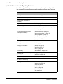
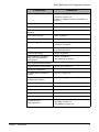
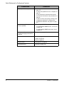
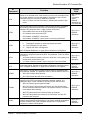
Quick Reference for Configuring Features
Quick Reference for Configuring Features
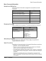
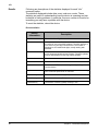
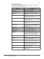
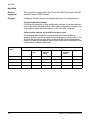
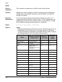
The following table shows common features that can be configured from
the command line, and the commands used to configure each feature.
Feature/Task
Configure Alarms
Commands
"set alarm" on page 46
Configuration management/Administration:
6
Backup/restore a configuration
from a TFTP server on the
network
"backup" on page 14
Update firmware
"boot" on page 15
Reset configuration to factory
defaults
"revert" on page 39
boot action=factory (see "boot" on page 15)
Reboot the device
"boot" on page 15
Connectware Device Protocol
configuration settings
"set devicesecurity" on page 57
"set mgmtconnection" on page 74
"set mgmtglobal" on page 77
"set mgmtnetwork" on page 78
Custom menus
"set menu" on page 69
Display current configuration
settings in a device
"show" on page 144
Display device statistics
"info" on page 25
Display device status
"display" on page 19
"status" on page 147
"who" on page 149
Forwarding
"set forwarding" on page 62
General Purpose Input/Output
(GPIO) pins
"set gpio" on page 63
"set alarm" on page 46
Help on device commands
"help" on page 24
Host name for a device (Specify
a name for the device)
"set host" on page 68
Manage connections
"connect" on page 18
"reconnect" on page 38
"rlogin" on page 42
"telnet" on page 148
"who" on page 149
"close" on page 17
"kill" on page 33
Chapter 1 Introduction
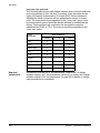
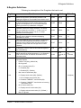
Quick Reference for Configuring Features
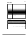
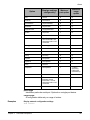
Feature/Task
Commands
Modem emulation
"set pmodem" on page 102
"set serial" on page 116
Chapter 3, "Modem Emulation Commands" on
page 151
Network access control
"set accesscontrol" on page 44
Network configuration
"set network" on page 84
Network services, enabling and
disabling
"set service" on page 118
Ping a host or device
"ping" on page 36
Point to Point Protocol (PPP)
"set pppoutbound" on page 104
Port buffering
"display buffers" on page 21
"set buffer" on page 55
RealPort (COM port redirection)
See the RealPort Installation Guide for details on
configuring this feature.
Remote login (rlogin)
"rlogin" on page 42
Network Address Translation
(NAT) and port forwarding
configuration
"set nat" on page 81
"set forwarding" on page 62
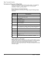
Security/access control features:
Control access to inbound ports
"set service" on page 118
Serial port configuration:
Chapter 1
Introduction
Enable/disable command-line
access
"set term" on page 126
General serial port
communication options
"set serial" on page 116
Port profiles
"set profile" on page 110
RCI serial mode
"set rciserial" on page 113
RTS Toggle
"set rtstoggle" on page 114
TCP serial connections
"set tcpserial" on page 123
UDP serial characteristics
"set udpserial" on page 127
Automatically connect to a server
or network device
(autoconnection)
"set autoconnect" on page 51
"set serial" on page 116
"set tcpserial" on page 123
7
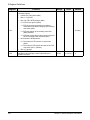
Quick Reference for Configuring Features
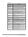
Feature/Task
Security and access permissions
Commands
•
•
•
•
Simple Network Management
Protocol (SNMP)
•
•
•
8
To change user name for a user: "set user" on
page 131
To issue new password to user: "newpass" on
page 35
To set permissions associated with various
services and commands: "set permissions" on
page 86
To add or remove user groups, change group
configuration attributes, or display group
configuration attributes: "set group" on page
65
To configure SNMP: "set snmp" on page 120
To enable/disable SNMP service: "set service"
on page 118
To enable/disable SNMP alarm traps: "send"
on page 43
Set system information: assign
system-identifying information to
a device
"set system" on page 122
Telnet to network devices
"telnet" on page 148
"mode" on page 34
"send" on page 43
Wired devices
"set ethernet" on page 60
Wireless devices
"set wlan" on page 136
Chapter 1 Introduction
Basic Command Information
Basic Command Information
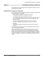
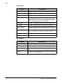
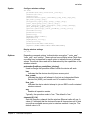
Navigation and Editing Keys
Use the keys listed in the table to navigate the command line and edit
commands:
Action
Keys
Move the cursor back one space.
Ctrl+b
Move the cursor forward one space.
Ctrl+f
Delete the character to the left of the cursor.
Back space or Ctrl+h
Delete the character under the cursor.
Delete
Scroll back through commands.
Ctrl+p
Scroll forward through commands.
Ctrl+n
Execute the command.
Enter
Displaying Online Help
Help is available for all commands. The table describes how to access it.
For information on...
Type
All commands
? (with no additional options)
A specific command
help [command]
OR
[command] ?
Example: help info
Example: info ?
Example: set alarm ?
Abbreviating Commands
All commands can be abbreviated. Simply supply enough letters to
uniquely identify the command.
Syntax Conventions
Presentation of command syntax in this manual follows these conventions:
• Brackets [ ] surround optional material.
• Braces { } surround entries that require you to chose one of several
options, which are separated by the vertical bar, |.
• Non-italicized text indicates literal values, that is, options or values that
must be typed exactly as they appear. Yes and no options are examples
of literals.
• Italicized text indicates that a type of information is required in that
option. For example, filename means that the name of a file is required
in the option.
Chapter 1
Introduction
9
Basic Command Information
Entering Special Characters in String Values
Several commands have options that are string values, for example the
“set alarm” command’s “match” option and the “set autoconnect”
command’s “connect_on_string” option.
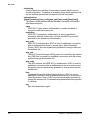
Escape Sequences for Special Characters
Special characters can be entered in strings using the following escape
sequences:
Escape
Sequence
Processed as:
\*
Match any character. This escape sequence is only available on the
“set alarm match=string” option.
\a
Alert character.
\b
Backspace character.
\f
Form-feed character.
\n
New-line character.
\r
Carriage-return character.
\s
Acts as a separator between characters. This sequence allows you to
enter a string such as “\xB8\s4” where you want the B8 translated as
a hexadecimal character separate from the numeric character 4.
\t
Horizontal tab character.
\v
Vertical tab character.
\\
Backslash character ( \ ).
\xN
A hexadecimal number, where N is up to 20 hexadecimal digits. For
example: \x10\x2
\N
An octal byte, where N is up to 3 octal digits. For example: \2 or
\208
Length Limitations on String Vales
String values for certain command options have specific limitations on the
maximum total string value including special characters, and the maximum
parsed value (that is, the character-string length when any escape
sequences in the string are processed). The option descriptions note these
maximum lengths.
10
Chapter 1 Introduction
Access the Command Line
Access the Command Line
To configure devices using commands, you must first access the command
line from a Telnet session, and then log on as needed.
This procedure assumes that you have configured the Digi device with an
IP address already.
1. To Telnet to the device server, enter the following command from a
command prompt on another networked device, such as a server:
telnet ip-address
where ip-address is the device server’s IP address. For example:
telnet 192.3.23.5
2. If security is enabled for the device, (that is, a username and password
have been set up for the device), a login prompt is displayed. If you do
not know the user name and password for the device, contact the
system administrator who configured the device.
Configure an IP Address
If the device to which you will be issuing commands has not already been
assigned an IP address, or if the IP address needs to be modified from its
initial configuration, see the Digi Connect User’s Guide for details on
configuring an IP address.
Chapter 1
Introduction
11
Configure an IP Address
12
Chapter 1 Introduction
Verifying Device Support for Commands
Command Descriptions
Chapter 2
This chapter provides a description of each command in the Digi Connect
Command-Line Interface.
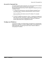
Verifying Device Support for Commands
For verification that a device supports a particular command, you can enter
several commands. For example:
• “help” displays all supported commands for a device.
• “?” displays all supported commands for a device
• “set ?” displays the syntax and options for the “set” command. You can
use this to determine whether the device includes a particular “set”
command variant.
• “help set” displays syntax and options for the “set” command.
• “set serial ?” displays the syntax and options for the “set serial”
command.
• “help set serial” displays the syntax and options for the “set serial”
command.
Some options may become available in new firmware revisions or before
new documentation is released.
Some commands relate only to particular features unique to specific
devices. For example, the “set wlan” command applies only to wireless
devices. Other commands may have options that are specific to features
that are not available on all devices. For example, the “display” command’s
“mobile” option applies only to Digi Connect WAN and Digi Connect RG
devices.
Chapter 2
Command Descriptions
13
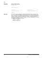
backup
backup
Devices
supported
This command is supported in all Digi Connect Family devices.
Purpose
Use the backup command to save or restore the device configuration from
a TFTP server located on the network.
Required
permissions
Permissions must be set to “set permissions backup=execute” to use this
command. See "set permissions" on page 86 for details on setting user
permissions for commands.
Syntax
backup [to=serv eri paddress[:filename]|
from=ser ver ipaddress[:filename]|print]
Options
to=serveripaddress[:filename]
The IP address of the TFTP server to which the configuration will be
saved, and the filename that the configuration will be saved as. If a
filename is not specified, the default filename of config.rci is used.
from=serveripaddress[:filename]
The IP address of the TFTP server and the filename from which the
configuration will be restored. If a filename is not specified, the default
filename of config.rci is assumed.
print
Prints out the current device configuration.
Example
backup from=10.0.0.1:config.rci
See also
"set rciserial" on page 113. The “set rciserial” command allows a
configuration file to be loaded over a serial port when the DSR input signal
is high.
14
Chapter 2 Command Descriptions
boot
boot
Devices
supported
This command is supported in all Digi Connect Family devices.
Purpose
The boot command is used to reboot the device server, restore the device
configuration to factory default settings, and load new firmware (both EOS
and POST images) from a TFTP server.
Required
permissions
Permissions must be set to “set permissions boot=execute” to use this
command. See "set permissions" on page 86 for details on setting user
permissions for commands.
Syntax
Reboot the device server
boot action=reset
Restore configuration defaults
boot action=factory
Load new firmware into flash ROM from a TFTP host
boot load=host -ip -ad dre ss:lo ad- fil e
Options
action
The action to be performed.
factory
Resets the entire configuration to factory defaults, then reboots the
device.
reset
Reboots the device.
load
The firmware to be loaded.
host-ip-address
The IP address of a host with new firmware, which is then burned into
flash ROM. The host must be running a TFTP server.
load-file
The name of the firmware file.
Chapter 2
Command Descriptions
15
boot
Examples
Restore configuration defaults
This example reloads the firmware stored in flash ROM and resets the
configuration to factory defaults then reboots the device.
boot action=factory
Reboot using the current firmware and configuration
This example reboots the device and uses the current firmware and
configuration stored in flash ROM.
boot action=reset
Reboot using firmware from a boot host
This example loads the firmware stored on the TFTP host into flash ROM.
A reboot is required to use the new firmware.
boot load=10.0.0.1:firmware.bin
See also
16
"revert" on page 39
Chapter 2 Command Descriptions
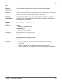
close
close
Devices
supported
This command is supported in all Digi Connect Family devices.
Purpose
Closes active connect, Rlogin, and Telnet sessions; that is, sessions
opened by “connect,” “rlogin,” or “telnet” commands.
The “close” command is associated with the sessions displayed by the
“status” command.
A “close” command issued without any options closes the current
connection.
To issue the “close” command, you must escape the active session. Do this
by pressing the escape key defined for your session type. The following
table lists default escape keys.
Session Type
Default Escape Keys
Connect
Ctrl+[+Enter
Rlogin
~+Enter
Telnet
Ctrl+]+Enter
Syntax
close [{*|conn ect ion -nu mber }]
Options
*
Closes all active sessions.
connection-number
Identifies the session to close by its session number.
Examples
Close a session identified by number
close 1
Close the current session
close
Close all active sessions
close *
See also
•
"kill" on page 33. The kill command has a broader effect than close, and
lets you kill connections from the global list. That is, it is not limited to
sessions associated with the current connection.
•
"status" on page 147 for information on displaying status information on
active sessions.
"connect" on page 18
"rlogin" on page 42
"telnet" on page 148
•
•
•
Chapter 2
Command Descriptions
17
connect
connect
Devices
supported
This command is supported in all Digi Connect Family devices.
Purpose
Used to make a connection, or establish a session, with a serial port.
There are several ways of using the connect command:
• To make multiple connections, issue multiple connect commands.
• To temporarily suspend a connection, escape the active session by
pressing Ctrl [.
• To temporarily suspend a connection and return to the command line,
press the escape character and then the Enter key.
• To switch between active sessions (without first escaping to the
command line), press the escape character and then the number of the
session you wish to enter. Pressing the connect escape character twice
causes the next session to appear, enabling you to easily page through
sessions.
Required
permissions
Permissions must be set to “set permissions connect=execute” to use this
command. See "set permissions" on page 86 for details on setting user
permissions for commands.
Syntax
connect ser ial_ por t
Options
serial_port
The number of the port on which to establish a connection.
Example
The following command creates a connection to port 1:
connect 1
See also
18
•
•
"close" on page 17 for information on ending a session.
"reconnect" on page 38 for information on reestablishing a port
connection.
Chapter 2 Command Descriptions
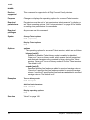
display
display
Devices
supported
This command is supported in all Digi Connect Family devices.
Purpose
Use the display command to status information for a device. Command
options allow for displaying a variety of status information, including:
• General product information, including the product name, MAC
address, boot, post, and firmware versions, memory usage, utilization,
and uptime, or the amount of time since the device was last booted.
• Access control status information
• GPIO signals.
• Memory usage information only.
• Mobile (cellular modem) status information.
• Network Address Table (NAT) status information
• Point-to-Point Protocol (PPP) status information
• Serial modem signals (DTR, RTS, CTS, DSR, DCD).
• Uptime information only.
• Boot, POST and EOS firmware version information and Digi part
numbers for those items
• Typical wireless LAN (WLAN) parameters for wireless devices.
Required
permissions
Permissions must be set to “set permissions display=execute” to use this
command. See "set permissions" on page 86 for details on setting user
permissions for commands.
Syntax
display
{accesscontrol|device|gpio|memory|mobile|nat|pppstats|serial|
uptime|version|wlan}
Options
accesscontrol
Displays access control status information.
device
Displays general product information including product name, MAC
address, boot, post, and firmware versions, memory usage, utilization,
and uptime. The information displayed by this option is the same as that
displayed by the “info device” command (see "info" on page 25).
gpio
Displays GPIO signals.
memory
Displays general memory, network memory, and streams memory
usage.
mobile
Displays mobile (cellular modem) status information. (This option applies
to Digi Connect WAN and Digi Connect RG devices only.)
Chapter 2
Command Descriptions
19
display
nat
Displays Network Address Table (NAT) status information.
pppstats
Displays Point-to-Point Protocol (PPP) status information.
serial
Displays serial modem signals (DTR, RTS, CTS, DSR, DCD).
uptime
Displays amount of time since the device was booted.
version
Displays boot, POST and EOS firmware version information and Digi part
numbers for those items.
wlan
Displays typical wireless LAN (WLAN) parameters for wireless devices.
Example
display device
See also
The “display” command’s focus is on real-time information. In contrast, the
“info” command displays statistical information about a device over time,
while the “status” command displays the status of outgoing connections
(connections made by “connect,” “rlogin,” or “telnet” commands). For more
information, see these commands:
• "info" on page 25.
• "status" on page 147
20
Chapter 2 Command Descriptions
display buffers
display buffers
Devices
supported
This command is supported in all Digi Connect devices except the Digi
Connect WAN.
Purpose
The display buffers command is used to display the contents of a port
buffer, or Transfer the contents of a port buffer to a server running Trivial
File Transfer Protocol (TFTP). Port buffering is enabled by the “set buffer”
command (see "set buffer" on page 55). Contents are displayed in log form.
Required
permissions
To use this command, permissions must be set to one of the following:
• For a user to display the contents of a port buffer for the line on which
they are logged in: “set permissions buffers=r-self” or higher.
• For a user to display the contents of a port buffer for any line:
“set permissions buffers=read” or higher.
See "set permissions" on page 86 for details on setting user permissions
for commands.
Syntax
display buffers [port=r ange ] {[screen] [lines=n umb er]
[tail=num ber ] | tftp=s erv er:f ile nam e}
Options
port=range
The port or ports to which the command applies. Optional on a single-port
device.
screen
Displays the port buffer contents on the screen when screen is specified.
lines=number
The number of lines of data to display at a time when the “screen” option
is specified. Use 0 to indicate continuous flow.
tail=number
The total number of lines in the buffer to be displayed. The number is
calculated from the end of the buffer counting back.
tftp=server:filename
server
The IP address or DNS name of a server running TFTP to which buffer
information should be transferred.
filename
The name to use for the file that will be transferred to the TFTP server.
If the “port” option specifies more than one port, one file will be
transferred for each port. The filename for each port will be
filename_n, where n is the port number.
Chapter 2
Command Descriptions
21
display buffers
Examples
Display port buffering information on the screen
display buffers port=2 screen lines=32 tail=30
Output buffering information to a TFTP server
display buffers port=2 tftp=192.168.1.1:port_ouput
Output multi-port buffering information to a TFTP server
display buffers port=2-3 tftp=192.168.1.1:port_ouput
Note that port 2 buffering information goes to file port_output_2 and port 3
buffering information goes to file port_output_3.
See also
22
•
"set buffer" on page 55
Chapter 2 Command Descriptions
exit
exit
Devices
supported
This command is supported in all Digi Connect Family devices.
Purpose
Use the exit command to terminate your current session.
Syntax
exit
Example
exit
See also
"quit" on page 37. The quit and exit commands perform the same
operation.
Chapter 2
Command Descriptions
23
help
help
Devices
supported
This command is supported in all Digi Connect Family devices.
Purpose
Displays help about a specific command.
Syntax
help [command]
OR
[command]?
Examples
help boot
boot?
help set serial
set serial?
See also
24
"Displaying Online Help" on page 9.
Chapter 2 Command Descriptions
info
info
Devices
supported
This command is supported in all Digi Connect Family devices.
Purpose
This command prints out statistical information about a device. Command
options allow display of the following categories of statistics:
• Device statistics
• Ethernet statistics
• ICMP statistics
• IP statistics
• Serial statistics
• TCP statistics
• UDP statistics
• WLAN statistics (For wireless devices only)
The statistics in these tables are those gathered since the tables were last
cleared.
Syntax
info {device|ethernet|icmp|ip|serial|tcp|udp|wlan}
Options
For a description of the statistics displayed by all these options, see
“Results” on the following page.
device
Displays statistics from the device table. This information includes
device-model information, MAC address, current Boot and POST code,
firmware, memory usage, utilization, and uptime. The information
displayed by this option is the same as that displayed by the
“display device” command (see "display" on page 19).
ethernet
Displays statistics from the Ethernet table.
icmp
Displays statistics from the ICMP table.
ip
Displays statistics from the IP table.
serial
Displays statistics from the serial table. For descriptions of these
statistics, see "Results" on page 26.
tcp
Displays statistics from the TCP table.
udp
Displays statistics from the UDP table.
wlan
Displays statistics from the wireless Ethernet (wlan) table.
Chapter 2
Command Descriptions
25
info
Results
Following are descriptions of the statistics displayed for each “info”
command option.
The statistics displayed include data, event, and error counts. These
statistics are useful in understanding how the device is operating and can
be helpful in finding problems. In particular if an error counter is found to be
increasing you may have a problem with the device.
To reset the statistics, reboot the device.
Device statistics
Device
Information
26
Description
Product
The model of the Digi Connect device.
MAC Address
A unique network identifier. All network devices are required
to have their own unique MAC address. The MAC address is
on a sticker on your Digi Connect device. The number is
displayed as 12 hexadecimal digits, usually starting with
00:40:9D.
Firmware Version
The current firmware version. This information may be used
to help locate and download new firmware. Firmware updates
may be downloaded from the Digi Support website.
Boot Version
The current boot version.
Post Version
The current POST version.
CPU Utilization
The amount of CPU resources being used by the Digi
Connect device.
Uptime
The amount of time the Digi Connect device has been running
since it was last powered on or rebooted.
Total Memory
The total amount of memory (RAM) available.
Free Memory
The amount of memory (RAM) currently not being used.
Used Memory
The amount of memory (RAM) currently in use.
Chapter 2 Command Descriptions
info
Ethernet statistics
Statistic
Description
InBytes
Number of bytes received.
OutBytes
Number of bytes sent.
InUcastPkts
Number of Unicast packets received.
OutUcastPkts
Number of Unicast packets sent.
InNonUcastPkts
Number of non-Unicast packets received.
OutNonUcastPkts
Number of non-Unicast packets sent.
InDiscards
Number of incoming packets that were discarded.
OutDiscards
Number of outgoing packets that were discarded.
InErrors
Number of incoming packets that contained errors.
OutErrors
Number of outgoing packets that contained errors.
RxOveruns
Number of Rx overruns. Rx overruns are generally caused by
the inability of the device to get sufficient bus bandwidth to
offload the data.
TxResets
Number of times the transmitter has been reset.
InUnknownProtos
Number of incoming packets where the protocol was
unknown.
ICMP statistics
Statistic
Chapter 2
Description
InMessages
Number of incoming messages.
OutMessages
Number of outgoing messages.
InDestUnreachables
Number of incoming destination-unreachable messages
received. A destination-unreachable message is sent to the
originator when a datagram fails to reach its intended
destination.
OutDestUnreachables
Number of destination-unreachable messages sent. A
destination-unreachable message is sent to the originator
when a datagram fails to reach its intended destination.
InErrors
Number of incoming received messages with errors.
Command Descriptions
27
info
IP statistics
Statistic
28
Description
InReceives
Number of datagrams received.
OutRequests
Number of datagrams given to IP to transmit.
InAddressErrors
Number of received datagrams discarded because they
were for another host and could not be forwarded.
DatagramsForwarded
Number of received datagrams forwarded to another host.
InHeaderErrors
Number of received datagrams discarded because of
invalid header information.
OutNoRoutes
Number of received datagrams discarded because no route
to the destination IP address could be found.
InUnknownProtos
Number of received datagrams discarded because the
specified protocol is not available.
OutDiscards
Number of outgoing datagrams that were discarded for
miscellaneous reasons. This statistic is not used and is
always zero.
InDiscards
Number of received datagrams discarded for
miscellaneous reasons.
FragCreates
Number of outgoing datagram fragments created.
ReassembleOks
Number of received datagrams that were successfully
reassembled from fragments.
FragOks
Number of outgoing datagrams that were fragmented.
FragFails
Number of outgoing datagram fragmentation attempts that
failed. This statistic is not used and is always zero.
AclExamines
Number of received datagrams examined for access
control filtering.
AclAccepts
Number of received datagrams accepted after being
examined by access control filtering.
AclDiscards
Number of received datagrams discarded after being
examined by access control filtering.
NatPrivateToPublic
Number of datagrams received from the private network,
successfully translated by NAT, and returned to IP to be
forwarded to the public network.
NatPublicToPrivate
Number of datagrams received from the public network,
successfully translated by NAT, and returned to IP to be
forwarded to the private network.
Chapter 2 Command Descriptions
info
Serial statistics
Statistic
Chapter 2
Description
rbytes
Total data in: the number of bytes received.
tbytes
Total data out: the number of bytes transmitted.
overrun errors
The number of times FIFO has overrun. The next data
character arrived before the hardware could move the
previous character.
overflow errors
The number of times the Received buffer has overrun. The
receive buffer was full when additional data was received.
frame errors
The number of framing errors detected. The received data did
not have a valid stop bit.
parity errors
The number of parity errors detected. The received data did
not have the correct parity setting
breaks
The number of break signals detected.
signal change
For each signal (CTS, DSR, RI, DCD, RTS, DTR), the number
of times the signal has changed states.
Command Descriptions
29
info
TCP statistics
Statistic
Description
InSegments
Number of segments received.
OutSegments
Number of segments sent.
InErrors
Number of segments received with errors.
RetransmitSegments
Number of segments retransmitted. Segments are
retransmitted when the server doesn't respond to a packet
sent by the client. This is to handle packets that might get
lost or discarded somewhere in the network.
EstabResets
Number of established connections that have been reset.
OutResets
Number of outgoing connections that have been reset.
PassiveOpens
Number of passive opens. In a passive open, the Digi device
server is listening for a connection request from a client.
ActiveOpens
Number of active opens. In an active open, the Digi device
server is initiating a connection request with a server.
Established
Number of established connections.
Attempt Fails
Number of failed connection attempts.
UDP statistics
Statistic
30
Description
InDatagrams
Number of datagrams received.
OutDatagrams
Number of datagrams sent.
InErrors
Number of bad datagrams that were received. This number
does not include the value contained by "No Ports"
NoPorts
Number of received datagrams that were discarded because
the specified port was invalid.
Chapter 2 Command Descriptions
info
Wireless (WLAN) statistics
The WLAN statistics may aid in troubleshooting network communication
problems with your wireless network.
Statistic
Chapter 2
Description
TxFrames
Number of frames transmitted.
TxBroadcastFrames
Number of broadcast frames transmitted.
TxRtsFrames
Number of Request-to-Send (RTS) frames
transmitted.
TxRetries
Number of times an outgoing frame is
retransmitted because the acknowledgement
for the frame was not received.
TxDroppedRetries
Number of outgoing frames that were dropped
because the maximum number of retries were
exceeded for the frame.
TxDroppedBroadcasts
Number of broadcast frames dropped because
the acknowledgement for the frame was not
received.
TxDroppedAssoc
Number of outgoing packets dropped because
the device had not yet associated with a
wireless network
RxFrames
Number of received frames.
RxBroadcastFrames
Number of received broadcast frames.
RxRtsFrames
Number of RTS frames received.
RxRetries
Number of incoming frames that have the retry
bit set in their frame header. The retry bit
indicates that the other side has attempted to
transmit a given frame more than once.
RxDroppedNoBuffers
Number of received frames dropped due to no
buffer.
RxDropInvalid
Number of incoming frames dropped because
the frame appeared incorrect.
RxDropDuplicate
Number of incoming frames dropped because a
given frame had already been received.
RxDropAge
Number of fragmented frames dropped
because the fragment timed out before the rest
of the frame sequence was received.
RxDropDecrypt
Number of frames dropped because they were
not properly encrypted.
RxDropSize
Number of frames dropped because their frame
size was too big
Command Descriptions
31
info
Examples
Display ICMP statistics
#> info icmp
ICMP statistics:
See also
32
InMessages
: 14
OutMessages
: 0
InDestUnreachables
: 5
OutDestUnreachables
: 0
InErrors
: 0
The “info” command displays statistical information about a device over
time. In contrast, the “display” command’s focus is on real-time information,
while the “status” command displays the status of outgoing connections
(connections made by “connect,” “rlogin,” or “telnet” commands). For more
information, see these commands:
• "display" on page 19.
• "status" on page 147
Chapter 2 Command Descriptions
kill
kill
Devices
supported
This command is supported in all Digi Connect Family devices.
Purpose
Use the kill command to kill connections. The kill command is associated
with the connections displayed by the who command.
Required
permissions
Permissions must be set to “set permissions kill=execute” to use this
command. See "set permissions" on page 86 for details on setting user
permissions for commands.
Syntax
kill [ran ge] [co nne cti on_i d]
Options
range
A range of connection IDs.
connection_id
An ID for the connection.
Examples
Killing a session on a specific port
kill 1
Killing a session on a range of ports
kill 1-3
See also
•
•
•
Chapter 2
"close" on page 17, to close sessions created from the current
connection.
"status" on page 147, to display the list of current sessions.
"who" on page 149, for information on determining active connections.
Command Descriptions
33
mode
mode
Devices
supported
This command is supported in all Digi Connect Family devices.
Purpose
Changes or displays the operating options for a current Telnet session.
Required
permissions
Permissions must be set to “set permissions telnet=execute” to display or
set Telnet operating options. See "set permissions" on page 86 for details
on setting user permissions for commands.
Required
privileges
Anyone can use this command.
Syntax
Change Telnet options
mode [opt ions ]
Display Telnet options
mode
Options
options
The operating options for a current Telnet session, which are as follows:
binary={on|off}
Enables or disables Telnet binary mode is enabled or disabled.
“binary=on” turns on binary mode, which means that all transmitted
and received characters are converted to binary during this Telnet
session. “binary=off” turns off binary mode off for this Telnet session.
The default is off.
crmod={on|off}
Specifies whether line feeds are added to received carriage returns.
“crmod=on” specifies that line feeds are added to received carriage
returns. “crmod=off” specifies that line feeds are not added to received
carriage returns. The default is off.
Examples
Turn on binary mode
mode binary=on
Add line feed characters
mode crmod=on
Display operating options
mode
See also
34
"telnet" on page 148.
Chapter 2 Command Descriptions
newpass
newpass
Devices
supported
This command is supported in all Digi Connect Family devices.
Purpose
Use the newpass command to create or change user passwords for the
device.
Required
permissions
Permissions must be set to “set permissions newpass=rw-self” for a user to
set their own password, and “set permissions newpass=rw” to set another
user’s password. See "set permissions" on page 86 for details on setting
user permissions for commands.
Syntax
newpass [id=number|name=string]
Options
id=number
Specifies the ID of the user to be acted on.
name=string
Specifies the name of the user to be acted on.
Example
The “newpass” command initiates a dialog that changes the user’s
password.
User changing their own password
newpass
Changing another user’s password
newpass name=jdoe
See also
Chapter 2
See "set user" on page 131 for information on configuring users.
Command Descriptions
35
ping
ping
Devices
supported
This command is supported in all Digi Connect devices.
Purpose
Tests whether a host or other device is active and reachable.
To interrupt the “ping” command, use Ctrl-C.
Required
permissions
Permissions must be set to “set permissions ping=execute” for a user to
use this command. See "set permissions" on page 86 for details on setting
user permissions for commands.
Syntax
ping ipaddress [o pti ons]
Options
ipaddress
Identifies the target of the “ping” command by its IP address.
options
The options associated with the “ping” command, which are:
count=0|n
The number of “ping” commands to be issued. 0 means ping until
interrupted. The default is 0.
interval=milliseconds
The ping time in milliseconds. The default is 1000 milliseconds.
size=bytes
The number of bytes to send in each ping packet. The default is 56
bytes.
Examples
Specify a simple ping
The following command determines whether the specified host can be
reached:
ping 199.150.150.10
36
Chapter 2 Command Descriptions
quit
quit
Devices
supported
This command is supported in all Digi Connect Family devices.
Purpose
Use the quit command to log out of the device.
Syntax
quit
Example
quit
See also
"exit" on page 23. The “quit” and “exit” commands perform the same
operation.
Chapter 2
Command Descriptions
37
reconnect
reconnect
Devices
supported
This command is supported in all Digi Connect Family devices.
Purpose
Reestablishes a previously established connection; that is, a connection
opened by a connect, rlogin, or telnet command. The default operation of
this command is to reconnect to the last active session.
Required
permissions
Permissions must be set to “set permissions reconnect=execute” to use
this command. See "set permissions" on page 86 for details on setting user
permissions for commands.
Syntax
reconnect [{s eri al- por t|p=ser ial -po rt|s=se ssi on}]
Options
serial-port
The serial port to which this command applies. Use this option to
reconnect to a session opened by a connect command.
p=serial-port | s=session
The serial port number or session number (displayed by the “status”
command) to reconnect to.
Example
Reconnect to the last port used
reconnect
Reconnect to port 1
reconnect p=1
Reconnect to session 1
reconnect s=1
See also
•
•
•
•
•
38
"connect" on page 18 for information on establishing a connection on a
selected port.
"close" on page 17 for information on ending a connection.
"status" on page 147 for information on gathering status on current
connections.
"rlogin" on page 42
"telnet" on page 148
Chapter 2 Command Descriptions
revert
revert
Devices
supported
This command is supported in all Digi Connect Family devices.
Purpose
Sets a particular group of a devices’ settings to its default values.
If you enter "revert user," "revert group," or "revert permissions," a
message is displayed indicating that those settings cannot be reverted
individually, and instead must be reverted all together at the same time via
the “revert auth” command. The “revert auth” command (revert
authentication and authorization) reverts all users, all groups, and all
permissions at the same time.
Required
permissions
No “set permissions” option is required for all “revert” command variants
except “revert all.” The permissions used by the various “set” commands
apply to the various “revert” command variants. “revert all” uses a different
mechanism that bypasses the individual “set” commands, and therefore
has its own permissions. To execute the “revert all” command, a user must
have permissions set to “set permissions revert-all=execute”. See "set
permissions" on page 86 for details on setting user permissions for
commands.
Syntax
revert [all|accesscontrol|alarm|auth|autoconnect [port=range]|
buffer [port=r ang e]|
devicesecurity|forwarding|gpio|host|menu|mgmtconnection|
mgmtglobal|mgmtnetwork|nat|network|pmodem [port=ran ge]|
|pppoutbound [port=r ang e]|
profile [port=range]|serial [port=range]
service|snmp|system|tcpserial [port=range]|term [port=r ang e]|
udpserial [port=range]|user|wireless]
Options
all
Reverts everything except network settings.
alarm
Reverts the alarm settings configured by the “set alarm” command.
accesscontrol
Reverts the access control settings configured by the “set accesscontrol”
command.
auth
Reverts the permission settings configured by the “set permissions”
command, the user settings configured by the “set user” command, and
group settings, configured by the “set group” command.
autoconnect [port=range]
Reverts the Autoconnect settings configured by the “set autoconnect”
command.
buffer [port=range]
Reverts the port-buffering settings configured by the “set buffer”
command.
Chapter 2
Command Descriptions
39
revert
devicesecurity
Reverts the Connectware Device Protocol device security settings
configured by the “set devicesecurity” command.
forwarding
Reverts the port-forwarding settings configured by the “set forwarding”
command.
gpio
Reverts the GPIO settings configured by the “set gpio” command.
host
Reverts the host name set by the “set host” command.
menu
Reverts the custom menu settings configured by the “set menu”
command.
mgmtconnection
Reverts the Connectware Device Protocol connection settings
configured by the “set mgmtconnection” command.
mgmtglobal
Reverts the Connectware Device Protocol global settings configured by
the “set mgmtglobal” command.
mgmtnetwork
Reverts the Connectware Device Protocol network settings configured by
the “set mgmtnetwork” command.
nat
Reverts the Network Address Translation (NAT) and port/protocol
forwarding settings configured by the “set nat” command.
network
Reverts the network settings, configured by the “set network” command,
and the wireless configuration settings, configured by the “set wlan”
command.
pmodem [port=range]
Reverts the modem emulation settings, configured by the “set pmodem”
command.
pppoutbound [port=range]
Reverts the Point-to-Point Protocol (PPP) outbound connection settings,
configured by the “set pppoutbound” command.
profile [port=range]
Reverts the profile settings configured by the “set profile” command.
serial [port=range]
Reverts the serial settings configured by the “set serial” command.
service
Reverts the service settings configured by the “set service” command.
snmp
Reverts the SNMP settings configured by the “set snmp” command.
40
Chapter 2 Command Descriptions
revert
system
Reverts the system settings configured by the “set system” command.
tcpserial [port=range]
Reverts the TCP serial settings configured by the “set tcpserial”
command.
term [port=range]
Reverts the terminal connection settings configured by the “set term”
command.
udpserial [port=range]
Reverts the UDP serial settings configured by the “set udpserial”
command.
user
Reverts the user settings configured by the “set user” command.
wireless
Reverts the wireless settings configured by the “set wlan” command.
Example
Reset a device’s serial setting
The device serial setting is reset to the default serial configuration.
revert serial
Reset a serial port to default settings
revert serial port=2
See also
•
•
•
"boot" on page 15
The various “set” commands referenced in this description.
"show" on page 144
Chapter 2
Command Descriptions
41
rlogin
rlogin
Devices
supported
This command is supported in all Digi Connect devices.
Purpose
Performs a login to a remote system, also referred to as an rlogin.
Required
permissions
Permissions must be set to “set permissions rlogin=execute” to use this
command. See "set permissions" on page 86 for details on setting user
permissions for commands.
Syntax
rlogin [esc=(c har)] [{user=u ser -na me|-l us er- nam e}]
[ip_ add res s]
Options
esc
A different escape character than the ~ (tilde) character, which will be
used for the current Rlogin session. This character is used for
suspending a session from the remote host to return to the device server
command line.
user=user-name | -l user-name
The user name to use on the remote system. If you do not specify a
name, your device server user name will be used. The “-l user-name”
option is for compatibility with the UNIX “rlogin” command.
ip_address
The IP address of the system to which you are performing the remote
login.
Examples
rlogin 10.0.0.1
See also
•
•
•
•
42
"telnet" on page 148
"connect" on page 18
"status" on page 147
"close" on page 17
Chapter 2 Command Descriptions
send
send
Devices
supported
This command is supported in all Digi Connect Family devices.
Purpose
Sends a Telnet control command to the last active Telnet session.
Required
permissions
Permissions must be set to “set permissions telnet=execute” to display or
set Telnet operating options. See "set permissions" on page 86 for details
on setting user permissions for commands.
Required
privileges
Anyone can use this command.
Syntax
send {ao|ayt|brk|ec|el|escape|ga|ip|nop|synch}
Options
ao
Sends the “abort output” signal to discard output buffered on the peer.
ayt
Sends the “are you there” signal to test whether a host is still active.
brk
Sends the “break” signal to interrupt the executing application.
ec
Sends the “erase character” to delete the previous character.
el
Sends the “erase line” signal to delete the entire current line.
escape
Sends the “escape” character.”
ga
Sends the “go ahead” signal.
ip
Sends the “interrupt process” signal to terminate the program running on
the peer.
nop
Sends the “no option” signal to the peer.
synch
Sends the “synchronize process” signal to the peer.
Examples
Send an “interrupt process” signal
send ip
Send an “are you there” signal
send ayt
See also
Chapter 2
See "telnet" on page 148 for information on establishing Telnet sessions.
Command Descriptions
43
set accesscontrol
set accesscontrol
Devices
supported
This command is supported in Digi Connect WAN and Digi Connect RG
devices.
Purpose
Used to specify information that limits network access to this device, or
display current access-control settings. For the Digi Connect WAN, the
access-control settings also limit routing of packets through the device.
Required
permissions
To use this command, permissions must be set to one of the following:
• For a user to display the access control settings:
“set permissions s-accesscontrol=read”
• For a user to display and set access control settings:
“set permissions s-accesscontrol=rw”
Syntax
Configure access control settings
set accesscontrol [enabled={on|off}] [autoaddsubnets={on|off}]
[addrip[1-64]=ipaddress] [subnip[1-32]=ipaddress]
[subnmask[1-32]=mask]
Display current access-control settings
set accesscontrol
Options
enabled={on|off}
Used to enable access control. Care must be used with this command
because improper settings can render this device inaccessible from the
network. Specifically, setting this option to “on” with no “addrip” option
values specified will disable all access.
on
Enables access control.
off
Disables access control.
autoaddsubnets={on|off}
Used to enable the automatic adding of subnets and subnet masks to this
table. The IP subnets for the device server's network interfaces (Ethernet
and PPP), may be automatically added to the table. This permits access
by all IP sources on the device server's networks, without having to
explicitly identify either the subnet IP addresses (and netmasks) or
individual IP addresses.
on
Enables automatic adding of subnets and subnet masks.
off
Disables automatic adding of subnets and subnet masks.
addrip[1-64]=ipaddress
Used to specify up to 64 individual IP addresses that are allowed to
access this device.
44
Chapter 2 Command Descriptions
set accesscontrol
subnip[1-32]=ipaddress
Used to specify up to 32 subnet IP addresses. Any IP address in these
subnets will be allowed to access this device server.
subnmask[1-32]=mask
Used to specify a subnet mask associated with one of the 32 subnet IP
addresses.
Examples
Set access control settings
set accesscontrol enabled=on addrip1=143.191.1.228
Set access control for a specific subnet
This command will allow any IP address in the 143.191.2.0 subnet
(netmask 255.255.255.0) to access this device server:
set accesscontrol enabled=on subnip1=143.191.2.0
subnmask1=255.255.255.0
Display access control settings
set accesscontrol
See also
Chapter 2
"revert" on page 39
Command Descriptions
45
set alarm
set alarm
Devices
supported
Digi Connect EM, Digi Connect Wi-EM, Digi Connect ME, Digi Connect WiME, Digi Connect WAN, and Digi Connect RG. Setting alarms in GPIO
mode is not supported in the Digi Connect SP device.
Purpose
Use this command to configure device alarms or display current alarm
settings. Device alarms are used to send emails or SNMP traps when
certain device events occur. These events include changes in GPIO
signals and data patterns in the serial stream. Up to 32 alarms can be
configured in Digi Connect devices.
Required
permissions
Permissions must be set to “set permissions s-alarm=read” to display
current alarm settings, and to “set permissions s-alarm=rw” to display
alarm settings and configure alarms. See "set permissions" on page 86 for
details on setting user permissions for commands.
Syntax
Set alarms with general options (applies to all alarms)
set alarm [state={on|off} | mailserverip=ipaddress | from=string]
Set alarms with a range (set multiple alarms)
set alarm range={1-n }
[active={on|off}|to=string|cc=string|subject=string|
priority={normal|high}|mode={match|gpio}|
type={email|snmptrap|all}]
Set alarms in GPIO mode
set alarm range={1-n } mode=gpio
[pins=list_of_pins|highpins=list_of highpins|
lowpins=list of lowpins|pin{n}={high|low|ignore}|
trigger_interval=seconds|reminder={on|off}|
reminder_interval=seconds]
Note:
n is the pin number.
Set alarms in match mode
set mode=match match=s tri ng
Display current alarm settings
set alarm [range={1-n }]
46
Chapter 2 Command Descriptions
set alarm
Options
Options for setting alarms with general options
from=string
The text to be included in the “from” field of an alarm-triggered email.
mailserverip=ipaddress
Used to configure IP address of the mail server to which alarm-triggered
emails are sent.
state= {on|off}
Enables or disables all alarms.
on
Enables all alarms.
off
Disables all alarms.
The default is “off.”
Options for setting alarms with a range (set multiple alarms)
The following options apply to setting multiple alarms using a “range”
option.
range= {1-n}
All alarm options require a “range” option that is used to select the alarm
or range of alarms to set the options on. This “range” option is used to
specify the indices of the alarms to which the other options will be
applied.
active={on|off}
Enables or disables an alarm.
on
Enables an alarm.
off
Enables an alarm.
The default is “off.”
cc=string
The text to be included in the “cc” field of an alarm triggered email.
mode={match|gpio}
The alarm mode, which determines what type of event will trigger an
alarm.
match
Specifies that an alarm will be triggered when a pattern is found in the
stream of serial data.
gpio
Specifies that the transitions for GPIO pins will trigger alarms. See
"Options for setting alarms in GPIO mode" on page 49 for more
information about GPIO.
The default is “gpio” for all Digi Connect devices except Digi Connect SP.
For Digi Connect SP, the only option available is “match.”
Chapter 2
Command Descriptions
47
set alarm
priority={normal|high}
The priority of the triggered email.
normal
The email is sent with normal priority.
high
The email is sent with high priority.
The default is normal.
The default is off.
subject=string
If “type=email,” this option specifies the text to be included in the “subject”
field of an alarm-triggered email. If “type=snmptrap,” this option specifies
the text to be included in the “Serial Alarm Subject” field of an alarmtriggered SNMP trap.
to=string
The text to be included in the “to” field of an alarm-triggered email.
type={email|snmptrap|all}
Used to determine what kind of an alarm is sent: an e-mail alarm, an
SNMP trap or both.
In order for SNMP traps to be sent, the IP address of the system to which
traps are sent must be configured, by issuing a “set snmp” command with
the “trapdestip” option. See "set snmp" on page 120.
email
An email alarm is sent.
snmptrap
An SNMP trap is sent. If snmptrap is specified, the “subject” text is sent
with the alarm. The MIB for this trap is named
DIGI-SERIAL-ALARM-TRAPS.mib.
all
Both an email alarm and SNMP trap are sent.
The default is “email.”
48
Chapter 2 Command Descriptions
set alarm
Options for setting alarms in GPIO mode
In GPIO mode, alarms are triggered when there are transitions between
states for GPIO pins. The following options allow you set which GPIO pins’
transitions will trigger alarms.
pins=list_of_pins
A list of GPIO pins that trigger alarms.
highpins=list_of_highpins
A list of GPIO pins that trigger alarms when a pin’s signal is high.
lowpins=list_of_lowpins
A list of GPIO pins that trigger alarms when a pin’s signal is low.
pin{n}={high|low|ignore}
This option is an alternative way to specify the action of a given GPIO pin,
where n is the pin number.
high
The pin will trigger an alarm when the pin’s signal is high.
low
The pin will trigger an alarm when the pin’s signal is low.
ignore
The pin will not trigger an alarm.
The default is “ignore.”
reminder={on|off}
Specifies the type of reminder sent.
on
An email or SNMP trap is sent periodically while the alarm-triggering
event is active. The interval is based on the value of the
“reminder_interval” option.
off
An email or SNMP trap is sent only when an alarm is triggered.
reminder_interval=seconds
The minimum reminder interval in seconds. Indicates how often an email
or SNMP trap is sent when the “reminder” option is set to “on” and an
alarm-triggering event is active.
trigger_interval=seconds
The minimum trigger interval in seconds. If the “reminder” option is set to
“off,” this option indicates the minimum amount of time that is allowed
between alarm-triggered emails or SNMP traps.
Chapter 2
Command Descriptions
49
set alarm
Options for setting alarms in match mode
In match mode, an alarm will be triggered when a pattern is found in the
stream of serial data. The following options are used for setting alarms in
match mode:
mode=match
Sets the alarm to match mode.
match=string
A string that triggers an alarm if the data pattern is found in the incoming
serial stream. The maximum length of this string is 40 characters,
including escape sequences for special characters. For more details on
the escape sequences, see "Entering Special Characters in String
Values" on page 10. The maximum parsed length of this string is 10
characters. That is, this string must reduce down to a 10-character string
when the escape sequences are processed.
Examples
Set an alarm to “on” state
set alarm state=on mailservip=10.0.0.1
Set alarm mode to GPIO mode
set alarm range=1 mode=gpio
Set alarm to designate which pins trigger alarm
set alarm range=1 pin2=high pin3=high
set alarm range=1 highpins=2,3
Set alarm to GPIO mode for specific pins and send SNMP traps
set alarm range=1 highpins=2,3 type=snmptrap
See also
•
•
•
50
"set gpio" on page 63. The set gpio command determines whether pins
act as GPIO input, GPIO output, or standard serial.
"set snmp" on page 120
"revert" on page 39
Chapter 2 Command Descriptions
set autoconnect
set autoconnect
Devices
supported
This command is supported in all Digi Connect Family devices.
Purpose
Used to establish an automatic connection (autoconnection) between the
serial port and a remote network destination, and to display current
autoconnect settings.
Required
permissions
To use this command, permissions must be set to one of the following:
• For a user to display autoconnect settings for the line on which they are
logged in: “set permissions s-autoconnect=r-self”
• For a user to display autoconnect settings for any line:
“set permissions s-autoconnect=read”
• For a user to display and set the autoconnect settings for the line on
which they are logged in: “set permissions s-autoconnect=rw-self”
• For a user to display autoconnect settings for any line, and set the
autoconnect settings for the line on which the user is logged in:
“set permissions s-autoconnect=w-self-r”
• For a user to display and set the autoconnect settings on any line:
“set permissions s-autoconnect=rw”
See "set permissions" on page 86 for details on setting user permissions
for commands.
Syntax
Configure autoconnect
set autoconnect [port=r ange ]
[state={on|off}]
[trigger={always|data|dcd|dsr}]
[service={raw|rlogin|ssl|telnet}]
[description={string}]
[ipaddress=ipaddress]
[ipport=ipport]
[connect_on_string=s tri ng]
[flush_string={on|off}]
[keepalive={on|off}]
[nodelay=on|off]
Display autoconnect settings
set autoconnect [port=r ange ]
Chapter 2
Command Descriptions
51
set autoconnect
Options
port=range
Used to specify the serial port. Optional on a single-port device.
state={on|off}
Enables or disables the autoconnect feature.
on
Enables the autoconnect feature.
off
Disables the autoconnect feature.
The default is off.
If you are using the serial port for another purpose, it is recommended
this value be set to “off.”
trigger={always|data|dcd|dsr|string}
Indicates which events from the serial port will trigger a network
connection to occur.
always
The serial port will continually attempt to keep a connection to a
remote network destination active.
data
The serial port will attempt a network connection whenever data
arrives on the serial port.
dcd
The serial port will attempt a network connection whenever the serial
port’s DCD signal goes high.
dsr
The serial port will attempt a network connection whenever the serial
port’s DSR signal goes high.
string
A connection will be made upon detecting a particular sting, specified
by the “connect_on_string” option, in the data from the serial port.
The default is “always.”
service={raw|rlogin|ssl|telnet}
The type of network connection that will be established.
raw
A connection without any special processing will occur.
rlogin
A remote login (rlogin) connection will occur.
ssl
A secure connection conforming to SSL (Secure Sockets Layer) Version
3 and Transport Layer Security (TLS) Version 1 will occur.
telnet
A connection with Telnet processing will occur.
The default is “raw.”
52
Chapter 2 Command Descriptions
set autoconnect
description=string
A name for descriptive purposes only.
ipaddress=ipaddress
The IP address of the network destination to which a connection will be
made.
ipport=ipport
The TCP port of the network destination to which a connection will be
made.
connect_on_string=string
When the value of the “trigger” option is string, this option specifies the
string that must be found in the serial data in order for a connection to
occur. The maximum length of this string is 32 characters, including
escape sequences for special characters. For more details on the escape
sequences, see "Entering Special Characters in String Values" on page
10. The maximum parsed length of this string is 32 characters. That is,
this string must reduce down to a 32-character string when the escape
sequences are processed.
flush_string={on|off}
Indicates whether the connect string, specified by the
“connect_on_string” option, is flushed or sent over the newly established
connection.
on
The connect string is flushed.
off
The connect string is sent over the newly established connection.
The default is on.
keepalive={on|off}
Indicates whether or not TCP keepalives will be sent for the specified
range of clients. If set to on, keepalives will be sent, if it is off, keepalives
will not be sent.
Configurable TCP keepalive parameters, for example, how many
keepalives to send and when to send them are configured globally via the
"set network" command (see "set network" on page 84).
nodelay={on|off}
Used to allow unacknowledged or smaller than maximum segment sized
data to be sent.
Note: The “nodelay” option disables Nagle’s algorithm, which is on by
default, for some TCP services. The purpose of Nagle's algorithm is to
reduce the number of small packets sent. Briefly Nagle's algorithm says
to hold on to outgoing data when there is either unacknowledged sent
data or there is less than maximum segment size (typically around 1500
bytes for Ethernet) worth of data to be sent. It does a good job at keeping
transmission efficient, but there are times where it is desirable to disable
it.
Chapter 2
Command Descriptions
53
set autoconnect
Examples
Set autoconnect on with trigger
This example shows setting autoconnect to connect to the TCP port (2101)
of the network IP destination when data arrives on the serial port.
set autoconnect state=on trigger=data ipaddress=10.0.0.1
ipport=2101
Allow outgoing data that is either unacknowledged or is less than maximum
segment size
set autoconnect port=1 nodelay=on
See also
54
•
•
•
"revert" on page 39.
"set network" on page 84.
"set serial" on page 116.
•
"set tcpserial" on page 123.
Chapter 2 Command Descriptions
set buffer
set buffer
Devices
supported
This command is supported in all Digi Connect Family devices.
Purpose
Configures buffering settings on a port, or displays the port buffer
configuration settings on all ports. The port buffering feature allows you to
monitor incoming ASCII serial data in log form.
Required
permissions
To use this command, permissions must be set to one of the following:
• For a user to display the port buffering settings for the line on which
they are logged in: “set permissions buffers=r-self”
• For a user to display the port buffering settings for any line:
“set permissions buffers=read”
• For a user to display and set the port buffering settings for the line on
which they are logged in: “set permissions buffers=rw-self”
• For a user to display the port buffering settings for any line, and set port
buffering settings for the line on which the user is logged in:
“set permissions buffers=w-self-r”
• For a user to display and set the port buffering settings on any line:
“set permissions buffers=rw”
See "set permissions" on page 86 for details on setting user permissions
for commands.
Syntax
Configure port buffering
set buffer [clear] [port=nu mbe r] [size=num ber ]
[state={on|off|pause}]
Display the port buffering configuration
set buffer [port=port]
Options
clear
Clears the contents of the specified buffer.
port
The port or ports to which the command applies.
size
The size in kilobytes to configure the buffer. Settings are configurable in
2-kilobyte increments. The maximum size is 64 kilobytes. The default is
32 kilobytes.
Chapter 2
Command Descriptions
55
set buffer
state
The buffering state, which can be any of the following:
on
The data will be buffered.
off
The data will not be buffered and all data will be cleared from the
buffer.
pause
The data will not be buffered, but data in the buffer will not be cleared.
Examples
Display port buffer configuration for all ports
set buffer
Configure buffers
In this example, the set buffer command sets the buffer state for port 1 to
on mode and the buffer size to 64 kilobytes.
set buffer port=1 state=on size=64
See also
56
"revert" on page 39.
Chapter 2 Command Descriptions
set devicesecurity
set devicesecurity
Devices
supported
This command is supported in all Digi Connect Family devices.
Purpose
Used to set or display the Connectware Device Protocol device security
settings.
Required
permissions
To use this command, permissions must be set to one of the following:
• For a user to display the Connectware Device Protocol device security
settings: “set permissions s-devicesecurity=read”
• For a user to display and set Connectware Device Protocol device
security settings: “set permissions s-devicesecurity=rw”
See "set permissions" on page 86 for details on setting user permissions
for commands.
Syntax
Configure Connectware Device Protocol device security settings
set devicesecurity [identityverificationform={simple|crypto}]
[discoverycodingscheme={nonenone|aesmd5|nonemd5}]
[messagepassingscheme= {nonenone|aesmd5|nonemd5}]
[clientkeysize={default|128bit|192bit|256bit}]
[keyencryptingkey=hexstring] [keygeneratingkey=hexstring]
[keyseed=hexstring]
Display current device security settings
set devicesecurity
Options
identityverificationform={simple| crypto}
Used to specify the type of authentication used by the server.
simple
The device will send its device ID to the server.
crypto
The device and the server will perform a cryptographic challengeresponse handshake.
Chapter 2
Command Descriptions
57
set devicesecurity
discoverycodingscheme={nonenone|aesmd5|nonemd5}
Used to specify the method of encryption used during the discovery
phase of the connection. The first option specifies the encryption mode,
the second option specifies the authentication mode.
nonenone
No encryption and no authentication.
aesmd5
AES encryption and MD5 authentication.
nonemd5
No encryption and MD5 authentication.
Only the “nonenone” value is allowed if the “identityverificationform”
option is set to “simple.” The “aesmd5” and “nonemd5” values are
permitted only if “crypto” is used for “identityverificationform.”
messagepassingscheme= {nonenone|aesmd5|nonemd5}
Used to specify the method of encryption used during the message
passing phase of the connection. The first option specifies the encryption
mode, the second option specifies the authentication mode.
nonenone
No encryption and no authentication.
aesmd5
AES encryption and MD5 authentication.
nonemd5
No encryption and MD5 authentication.
Only the “nonenone” value is allowed if the “identityverificationform”
option is set to “simple.” The “aesmd5” and “nonemd5” values are
permitted only if “crypto” is used for “identityverificationform.”
clientkeysize={default|128bit|192bit|256bit}
Used to specify the key size used for AES encryption.
default
Use the client default key size.
128bit
Use a 128-bit key.
192bit
Use a 192-bit key.
256bit
Use a 256-bit key.
58
Chapter 2 Command Descriptions
set devicesecurity
keyencryptingkey=hexstring
This key is a shared secret between the device server and Connectware
Manager. The value must be generated by Connectware Manager. It is
used when the “identityverificationform” option is set to “crypto.”
keygeneratingkey=hexstring
keyseed=hexstring
Examples
Set device security settings
set devicesecurity identityverificationform=crypto
discoverycodingscheme=aesmd5 messagepassingscheme=aesmd5
clientkeysize=256bit
keyencryptingkey=0x0123456789abcdef01234567890abcdef01234567890
abcdef0123456789abcdef
Display device security settings
set devicesecurity
See also
Chapter 2
"revert" on page 39
Command Descriptions
59
set ethernet
set ethernet
Devices
supported
This command is supported in Digi Connect SP, Digi Connect EM, and
Connect ME devices.
Purpose
Configures, adjusts, and displays Ethernet communications parameters.
Required
permissions
Permissions must be set to “set permissions s-ethernet=read” to display
Ethernet communications parameters, and “set permissions s-ethernet=rw”
to display and configure Ethernet communications parameters. See "set
permissions" on page 86 for details on setting user permissions for
commands.
Syntax
Configure Ethernet communications parameters
set ethernet [duplex={half|full|auto}] [speed={10|100|auto}]
Display Ethernet communications parameters
set ethernet
Options
duplex
Determines the mode the Digi device uses to communicate on the
Ethernet network. Specify one of the following:
half
The device communicates in half-duplex mode.
full
The device communicates in full-duplex mode.
auto
The device senses the mode used on the network and adjusts
automatically.
The default is “half.” If one side of the Ethernet connection is using auto,
the other side can set the duplex value to whatever is desired. If one
side uses a fixed value (for example, half-duplex), the other side has to
use the same.
60
Chapter 2 Command Descriptions
set ethernet
speed
Configures the Ethernet speed the Digi device will use on the Ethernet
network. Specify an appropriate setting for your Ethernet network, which
can be one of the following:
10
The device operates at 10 megabits per second (Mbps) only.
100
The device operates at 100 Mbps only.
auto
The device senses the Ethernet speed of the network and adjusts
automatically.
The default is “auto.” If one side of the Ethernet connection is using auto
(negotiating), the other side can set the Ethernet speed to whatever
value is desired. Or, if the other side is set for 100 Mbps, this side must
use 100 Mbps.
Examples
Configure 100 Mbps Ethernet speed
set ethernet speed=100
See also
Chapter 2
"set network" on page 84 to configure network communications
parameters.
Command Descriptions
61
set forwarding
set forwarding
Devices
supported
This command is supported in Digi Connect WAN devices only.
Purpose
Enables or disables IP routing, or forwarding of IP datagrams, between
network interfaces. IP forwarding must be enabled to allow the Network
Address Table and port forwarding features to work properly.
Required
privileges
To use this command, permissions must be set to one of the following:
• For a user to display the forwarding settings:
“set permissions s-router=read”
• For a user to display and set forwarding settings:
“set permissions s-router=rw”
See "set permissions" on page 86 for details on setting user permissions
for commands.
Syntax
Set forwarding settings
set forwarding [ipforwarding={on|off}]
Display forwarding settings
set forwarding
Options
ipforwarding={on|off}
Enables or disables IP forwarding.
on
Enables IP forwarding.
off
Disables IP forwarding.
Examples
Enable IP forwarding
set forwarding ipforwarding=on
See also
62
•
•
"set nat" on page 81
"revert" on page 39
Chapter 2 Command Descriptions
set gpio
set gpio
Devices
supported
This command is supported Digi Connect EM, Digi Connect Wi-EM, Digi
Connect ME, Digi Connect Wi-ME, Digi Connect WAN, and Digi
Connect RG devices.
Purpose
Used to:
• Configure General Purpose I/O (GPIO) pins. In normal operation, the
GPIO pins are used for the serial CTS, DCD, DSR, DTR, and RTS pins.
The set gpio command allows these GPIO pins to be used for different
purposes.
• Display current GPIO pin settings.
Required
permissions
Permissions must be set to “set permissions s-gpio=read” to display GPIO
pin settings, and “set permissions s-ethernet=rw” to display and configure
GPIO pins. See "set permissions" on page 86 for details on setting user
permissions for commands.
Syntax
Configure GPIO pins
set gpio range={1-n } mode={serial|input|output}
Display current GPIO pin settings
set gpio [range={1-n }]
Options
range={1-n}
Used to specify the index of the GPIO pin to manipulate, where n is the
maximum number of GPIO pins on the device.
mode={serial|input|output}
The mode of operation of the GPIO serial pin.
serial
Indicates normal serial operation.
input
Allows input of GPIO signals. This is used in conjunction with alarms
to trigger emails or SNMP traps indicating a particular signal change.
output
Allows output of GPIO signals. Currently, output of GPIO signals is not
supported in the command-line interface. The web user interface can
be used to toggle the output of GPIO signals between high and low.
The default is “serial” for all pins.
Chapter 2
Command Descriptions
63
set gpio
Default serial signal settings for GPIO pins
The default serial signal settings for the GPIO pins on a Digi Connect
device are as follows. Depending on the device, there are five or nine
GPIO pins.
Pin Number
Examples
Default Serial Signal
Signal Direction
GPIO 1
DCD
Input
GPIO 2
CTS
Input
GPIO 3
DSR
Input
GPIO 4
RTS
Output
GPIO 5
DTR
Output
GPIO 6
TXD
Output
GPIO 7
RXD
Input
GPIO 8
TXD for port 2
Output
GPIO 9
RXD for port 2
Input
Changing the operation of the GPIO signal pins
The following command changes GPIO pins 1-5 to allow input of GPIO
signals.
set gpio range=1-5 mode=input
See also
64
•
•
"revert" on page 39.
"send" on page 43, for details on setting up alarms that issue email
messages or SNMP traps when GPIO pins change.
Chapter 2 Command Descriptions
set group
set group
Devices
supported
This command is supported in Digi Connect WAN and Digi Connect RG
devices only.
Purpose
Used to create and manage user groups. You can use “set group” to do the
following:
• Add a group. A maximum of 32 groups can be defined.
• Remove groups.
• Change group configuration attributes.
• Display group configuration attributes.
In order to apply a common set of user settings to more than one user, it
may be desirable to create a group with the required settings and then
associate that group with multiple users. If a user is a member of one or
more groups, the user's effective permissions are the maximum of the
permissions of the user and all of the groups to which the user belongs.
Required
permissions
Permissions must be set to “set permissions s-group=read” to display
group configuration attributes, and “set permissions s-group=rw” to display
and set group configuration attributes. See "set permissions" on page 86
for details on setting user permissions for commands.
Syntax
Add a group
set group add id=number newname=string
Remove a group
set group remove {id=range|name=string}
Change group configuration attributes
set group {id=range|name=string} [newname=string]
[commandline={on|off}] [menu={none|index|name}]
[defaultaccess={none|commandline|menu}]
Display group configuration attributes
set group {id=range|name=string}
Display group configuration attributes for all groups
set group
Options
add
Add a group. New groups are created with no permissions. A maximum
of 32 groups can be defined.
remove
Remove groups.
id=range
Specifies the ID or range of IDs of the groups to be acted on.
Chapter 2
Command Descriptions
65
set group
name= string
Specifies the name of the group to be acted on.
newname=string
Specifies a new group name.
commandline={on|off}
Specifies whether the users in the group are allowed to access the
command line of the device.
on
Users can access the command line interface.
off
Users can not access the command line interface.
The default is “on.”
menu={none|index|name}
Specifies whether the users in the group are allowed to access the
custom menu interface of the device and defines the custom menu that
the users will have displayed.
none
Users are not allowed to access the custom menu interface.
index
Users are allowed to access the custom menu interface and will be
displayed the custom menu at the specified index
name
Users are allowed to access the custom menu interface and will be
displayed the custom menu using the specified name.
The default is “none.”
defaultaccess={none|commandline|menu}
Specifies the default access method and interface that users in the group
will be given upon logging into the device. Note that the specified
interface must be enabled for the group and have a valid menu if
specified.
none
The group has no default access to the device and the users are not
allowed to access either the command line interface or the custom
menu interface without explicitly specifying the access method.
commandline
The users will be displayed and given access to the command line
interface assuming the group has command line access rights
enabled.
menu
The users will be displayed and given access to the custom menu
interface and be displayed the custom menu as specified by the
“menu” option.
The default is “commandline.”
66
Chapter 2 Command Descriptions
set group
Default
permissions
When a new group is created, it has no permissions.
Examples
Add a new group
set group add newname=gurus id=4
Remove group 7
set group remove id=7
Set a new group name
set group id=4 newname=gurus
Set a group with command line access rights
set group id=4 commandline=on defaultaccess=commandline
Set a group with custom menu access rights to access the “my_menu”
custom menu
set group name=gurus menu=my_menu defaultaccess=menu
See also
•
•
•
•
"newpass" on page 35
"set menu" on page 69
"set permissions" on page 86
"set user" on page 131
Chapter 2
Command Descriptions
67
set host
set host
Device support
This command is supported in all Digi Connect Family devices.
Purpose
Configures a name for the device, also known as a host name, or displays
the current host name for the device.
Required
permissions
Permissions must be set to “set permissions s-host=read” to display the
current host name, and “set permissions s-host=rw” to display and set the
host name. See "set permissions" on page 86 for details on setting user
permissions for commands.
Syntax
Configure a name for the device
set host name=n ame
Display the current host name
set host
Options
68
name=name
The name for the device. The name can be up to 32 characters long, and
can contain any alphanumeric characters, and can also include the
underscore ( _ ) and hyphen ( -) characters.
Chapter 2 Command Descriptions
set menu
set menu
Devices
supported
This command is currently not supported in any Digi Connect Family
devices.
Purpose
The “set menu” command is used to create and modify custom menus.
There are several modes of using the “set menu” command:
• To update global settings for custom menus.
• To add or update custom menus.
• To add or update individual items in a custom menu.
Required
permissions
Permissions must be set to “set permissions s-menu=read” to display
custom menu settings, and “set permissions s-menu=rw” to display and set
custom menu settings. See "set permissions" on page 86 for details on
setting user permissions for commands.
Syntax
Updating Global Settings
set menu [quit_key=k ey] [quit_label=st ring ] [previous_key=k ey]
[previous_label=s tri ng] [presskey_label=str ing ]
Adding/Updating Custom Menus
set menu range=1-32|name=st rin g [newname=str ing ]
[title=str ing ] [subtitle=st rin g] [sortby={none|key|label}]
[columns=1-5] [direction={horizontal|vertical}]
Adding/Updating Custom Menu Items
set menu range={1-32)|name=st rin g} [item=1-32] [key=k ey]
[label=str ing ] [{command=st rin g|submenu=str ing }]
Options
Options for Updating Global Settings
quit_key=key
The key and text displayed on the custom menu next to the quit_label
that allows a user to quit the custom menu and close the associated
connection. The menu is closed when this key is pressed by the user.
The key is either 0-9, a-z, or A-Z. The default is “Q.” The key is case
insensitive; therefore, the keys “A” and “a“ will act the same.
quit_label=string
The text displayed on the custom menu next to the quit_key that allows
a user to quit and close the custom menu. The string is a short
description. If the string contains spaces, enclose it in double quotes. The
default is “Quit.”
Chapter 2
Command Descriptions
69
set menu
previous_key=key
The key and text displayed on the custom menu next to the
“previous_label” that allows a user to return to the previous menu when
they have previously selected a submenu. This option is only shown and
only valid when the displayed menu is an active submenu such that
pressing this key will return the user to the original menu. The default is
“R.“ The key is case insensitive; therefore, the keys “A” and “a“ will act
the same.
previous_label=string
The text displayed on the custom menu next to the “previous_key” that
allows a user to return to the previous menu when the current menu is a
submenu that was displayed when issuing a submenu command on
another menu. If the string contains spaces, enclose it in double quotes.
The default is “Return to Previous Menu.”
presskey_label=string
The text displayed after a user has finished an issued command. After the
user selects an option that executes a command, the command output
will be displayed until the command completes. At this time, processing
will be stopped and this text will be shown to inform the user to press any
key in order to continue. After a key is pressed, the custom menu will
once again be shown. If the string contains spaces, enclose it in double
quotes. The default is “Press any key to continue...”
Options for Adding/Updating Custom Menus
range=1-32
The index of the custom menu to create or update. A maximum of 32
menus can be created, and these menus are assigned index values 1 to
32. The index is solely used as a way to identify a custom menu by direct
index without having to type in a complete name. When creating a new
menu, both the “range” and the “newname” options must be specified.
When updating a custom menu, only the “range” or the “name” option
must be specified, but not both.
name=string
A short descriptive string used to identify a menu. The string is used only
to identify a menu when linking a user or other custom menu to this menu.
This option can be used rather than the “range” option when updating a
custom menu. If the string contains spaces, enclose it in double quotes.
newname=string
A short descriptive string used to identify a menu. This option is used to
create a new menu or to change the name of an existing menu. When a
new menu is being created, this option must be specified along with the
“range” option.
When an existing menu name is being changed, this option must be
specified along with either “range” or “name,” where “name” is the current
name of the menu.
If the string contains spaces, enclose it in double quotes.
70
Chapter 2 Command Descriptions
set menu
title=string
subtitle=string
The title and optional subtitle for a particular menu. The title is displayed
above the custom menu and the subtitle, if specified, is displayed
immediately below it. These strings are shown to the user accessing the
custom menu as a means to identify, explain, or describe a custom menu.
Note that when creating a new custom menu, the “title” option is required.
If the string contains spaces, enclose it in double quotes.
sortby={none|key|label}
The method by which menu items for the custom menu are ordered and
displayed to the user.
none
Organizes the menu items and display them in the order in which they
are defined.
key
Sorts the menu items by the keys assigned to the menu items. The sort
is case-insensitive.
label
Sorts the menu items based on an alpha-numeric sort of the labels
assigned to the menu label.
columns=1-5
The number of columns to display the menu items in to the user. This
option is used in order to help avoid scrolling by the user. For instance, a
custom menu with many entries may want to display the menu items over
3 columns whereas a custom menu with only a few menu items will
appear better using single column. Note that when using multiple
columns an attempt should be made to avoid long menu item labels to
help avoid possible horizontal scrolling. The default is 1.
direction={horizontal|vertical}
The direction in which to display and arrange menu items. This option
only applies when the value of the “columns” option is more than 1 since
a single column has no sense of direction other than vertical.
horizontal
The items will be displayed in order left-to-right first, then vertical.
vertical
The items will be displayed top-to-bottom first, then left-to-right.
In other words, the following graphic on the left is done using horizontal
direction while the one on the right uses vertical.
A
D
G
B
E
H
C
F
I
A
B
C
D
E
F
G
H
I
The default is “horizontal.”
Chapter 2
Command Descriptions
71
set menu
Options for Adding/Updating Custom Menu Items
range=1-32
The index of the custom menu to add menu items to. Either the “range”
or “name” option can be specified to add or update menu items for a
particular menu.
name=string
The name of the custom menu to add or update menu items for. This
option can be used rather than “range.” If the string contains spaces,
enclose it in double quotes.
item=1-32
The index of the menu item to add or update. There are a maximum of
32 menu items for a particular custom menu and are indexed 1 to 32.
key=key
The key to assign to the menu item. This key is displayed on the custom
menu next to the “label” value, and is used to select the particular menu
item. The user presses this key to select the corresponding menu item.
The key must be unique to the custom menu, so that no two menu items
for the same custom menu share the same key. The keys assigned to the
global settings for “quit_key” and “previous_key” are reserved, and may
not be assigned to a menu item.
label=string
The text displayed on the custom menu next to the “key” value that
describes the action that the menu item will take. When using multiple
columns with a custom menu (specified by the “columns” option), it is in
the best interest to keep these strings short in length to avoid scrolling. If
the string contains spaces, enclose it in double quotes.
command=string
The command that is executed when this menu item is selected. This
may be any valid command on the CLI (command line interface). The
user accessing the custom menu must have the necessary permissions
for the supplied command in order to properly execute the command.
Note that this option may not be combined with the “submenu” option. If
the string contains spaces, enclose it in double quotes.
submenu=string
The menu displayed to the user upon selecting the menu item.
Submenus allow multi-level menus to exist, and grouping of information
so that a user may access one or more submenus each with their own
distinct menu items. The string is the menu name identifying the custom
menu to link to. The menu must have already been created. Note that this
option may not be combined with the “command” option. If the string
contains spaces, enclose it in double quotes.
72
Chapter 2 Command Descriptions
set menu
Examples
Updating Global Settings
set menu quit_key=Q quit_label=”Quit” previous_key=R
previous_label=”Return to Previous Menu”
presskey_label=”Press any key to continue...”
Adding/Updating Custom Menus
Adding a new custom menu (implies that index 2 is not yet created):
set menu range=2 newname=my_menu title=”My Menu” sortby=key
columns=2 direction=horizontal
Updating an existing menu with a new menu name:
set menu name=my_menu newname=admin_menu
Updating an existing menu with new settings:
set menu name=admin_menu title=”Administration Menu”
subtitle=”Select an Option”
Adding/Updating Custom Menu Items
Adding a menu item for a custom menus (implies that index 1 is not yet
created):
set menu name=admin_menu item=1 key=1 label=”Connect Port 1”
command=”connect 1”
Updating a menu item to display another submenu:
set menu name=my_menu item=2 key=A label=”Go to Admin Menu”
submenu=”admin_menu”
See also
•
•
"set user" on page 131.
"revert" on page 39.
Chapter 2
Command Descriptions
73
set mgmtconnection
set mgmtconnection
Devices
supported
This command is supported in all Digi Connect Family devices.
Purpose
Used to set or display the Connectware Device Protocol connection
settings.
Required
permissions
To use this command, permissions must be set to one of the following:
• For a user to display the Connectware Device Protocol connection
settings: “set permissions s-mgmtconnection=read”
• For a user to display and set Connectware Device Protocol connection
settings: “set permissions s-mgmtconnection=rw”
See "set permissions" on page 86 for details on setting user permissions
for commands.
Syntax
Configure Connectware Device Protocol connection settings
set mgmtconnection [connenabled={on|off}]
[conntype={client|timed|serverinitiated}]
[timedperiod=period]
[timedoffset={immediate|oneperiod|randomtime}]
[lkaupdateenabled={on|off}]
[clntreconntimeout={none|timeout]
[svraddr[1-8]=string]
[secidx[1-8]=index]
Display Connectware Device Protocol connection settings
set mgmtconnection
Options
connenabled={on|off}
Used to specify whether or not this instance is enabled for use.
on
Enables this instance for use.
off
Disables this instance for use.
conntype={client|timed|serverinitiated}
Used to specify the connection type.
client
This is a client connection.
timed
This is a timed connection.
serverinitiated
This is a server-initiated connection.
74
Chapter 2 Command Descriptions
set mgmtconnection
timedperiod=period
For a timed connection, this option is used to specify the time interval in
minutes between the device server's attempts to connect to the
Connectware Manager server. If a device server is already in a
connection to a Connectware Manager when the time interval expires, it
will not start a new connection at that time. Rather, the device server will
start a new timed period timer, and it will again check whether it needs to
connect to the Connectware Manager when that new timer expires.
timedoffset={immediate|oneperiod|randomtime}
For a timed connection, this option is used to specify when the first timed
connection (to a Connectware Manager) should be attempted after the
device server boots.
immediate
Attempt to connect immediately.
oneperiod
Wait one full timed period, then attempt to connect.
randomtime
Wait some random interval of time, between 0 and the full timed
period, then attempt to connect.immediate
lkaupdateenabled={on|off}
In conjunction with a server-initiated connection, this option is used to
enable a connection to a Connectware Manager server for the purpose
of informing that server of the IP address of the device server. This
permits the Connectware Manager to connect back to the device server,
or to dynamically update a DNS with the IP address of the device.
on
Enables "last known address" connections to the Connectware
Manager.
off
Disables "last known address" connections to the Connectware
Manager.
clntreconntimeout={none|timeout}
Used to specify the client reconnect timeout value in seconds. If clientinitiated connections are enabled, the device server will wait this amount
of time after a connection to the Connectware Manager is ended, and
then it will reconnect to the Connectware Manager. The keyword “none”
turns off the timeout feature.
svraddr[1-8]=string
Used to specify one of eight possible Connectware Manager server
addresses. When the device server attempts to connect to a
Connectware Manager, it tries the server addresses in this list in the
order 1-8.
secidx[1-8]=index
Used to link a server address with a Device Security entry.
Chapter 2
Command Descriptions
75
set mgmtconnection
Examples
Set values for the client connection
set mgmtconnection connenabled=on conntype=client
clntreconnecttimeout=50
Display current connection settings
set mgmtconnection
See also
76
"set devicesecurity" on page 57
"revert" on page 39
Chapter 2 Command Descriptions
set mgmtglobal
set mgmtglobal
Devices
supported
This command is supported in all Digi Connect Family devices.
Purpose
Used to set or display the Connectware Device Protocol global settings, or
revert the device ID to factory settings.
Required
permissions
To use this command, permissions must be set to one of the following:
• For a user to display the Connectware Device Protocol global settings:
“set permissions s-mgmtglobal=read”
• For a user to display and set Connectware Device Protocol global
settings: “set permissions s-mgmtglobal=rw”
See "set permissions" on page 86 for details on setting user permissions
for commands.
Syntax
Configure Connectware Device Protocol global settings
set mgmtglobal [deviceid={hex string}]
Display Connectware Device Protocol global settings
set mgmtglobal
Revert the Device ID to factory settings
set mgmtglobal revertdeviceid
Options
deviceid={hex string}
Used to specify the device ID. The device ID is 32 hexadecimal digits,
preceded by the characters “0x.”
revertdeviceid
Used to revert the device id to factory settings. If the device’s MAC
address is GG:HH:JJ:KK:LL:MM, then the device ID is set to
0x0000000000000000GGHHJJffffKKLLMM.
Examples
Set the device id
set mgmtglobal deviceid=0x0123456789abcdef0123456789abcdef
See also
Chapter 2
"revert" on page 39
Command Descriptions
77
set mgmtnetwork
set mgmtnetwork
Devices
supported
This command is supported in all Digi Connect Family devices.
Purpose
Used to set or display the Connectware Device Protocol network settings.
Required
permissions
To use this command, permissions must be set to one of the following:
• For a user to display the Connectware Device Protocol network
settings: “set permissions s-mgmtnetwork =read”
• For a user to display and set Connectware Device Protocol network
settings: “set permissions s-mgmtnetwork =rw”
See "set permissions" on page 86 for details on setting user permissions
for commands.
Syntax
Configure Connectware Device Protocol network settings
set mgmtnetwork
[networktype={modemppp|ethernet|802.11}]
[connectionmethod={auto|none|mt|mdh|proxy}]
[proxyaddress=s tri ng]
[proxyport=port ]
[proxylogin=stri ng]
[proxypassword=s tri ng]
[proxypersistentconnection={on|off}]
[mtrxkeepalive=t ime]
[mttxkeepalive=t ime]
[mtwaitcount=c oun t]
[mdhrxkeepalive=t ime]
[mdhtxkeepalive=t ime]
[mdhwaitcount=c oun t]
Display Connectware Device Protocol network settings
set mgmtnetwork
Options
[networktype={modemppp|ethernet|802.11}
Used to specify which type of network to which this instance applies.
modemppp
This instance applies to the modem PPP network.
ethernet
This instance applies to the ethernet network.
802.11
This instance applies to the 802.11 network.
78
Chapter 2 Command Descriptions
set mgmtnetwork
connectionmethod={auto|none|mt|mdh|proxy}
Used to specify the Connectware Device Protocol firewall traversal
method.
auto
Automatically detect the connection method.
none
No firewall; connect using TCP.
mt
Connect using TCP.
mdh
Connect using HTTP.
proxy
Connect using HTTP over proxy.
proxyaddress=string
Used to specify the proxy host address when connection method is proxy
proxyport=port
Used to specify the proxy host port when connection method is proxy.
proxylogin=string
Used to specify the login string when connection method is proxy.
proxypassword=string
Used to specify the proxy password when connection method is proxy.
proxypersistentconnection={on|off}
Used to specify whether the device server should attempt to use HTTP
persistent connections when the connection method is "proxy". Not all
HTTP proxies correctly handle HTTP persistent connections. The use of
persistent connections can improve performance of the exchange of
messages between the device server and Connectware Manager, when
that connection is HTTP/proxy. The reason for this is that the same HTTP
connection can be reused for multiple consecutive HTTP requests and
replies, eliminating the overhead of establishing a new TCP connection
for each individual HTTP request/reply, then closing that connection
when the request is complete.
on
The device server should attempt to use HTTP persistent connections.
off
The device server should not attempt to use HTTP persistent
connections.
mtrxkeepalive=time
Used to specify the transmit keep alive time when connection method is
MT.
mttxkeepalive=time
Used to specify the receive keep alive time when connection method is
MT.
Chapter 2
Command Descriptions
79
set mgmtnetwork
mtwaitcount=count
Used to specify the wait count when connection method is MT.
mdhrxkeepalive=time
Used to specify the transmit keep alive time when connection method is
MDH.
mdhtxkeepalive=time
Used to specify the receive keep alive time when connection method is
MDH.
mdhwaitcount=count
Used to specify the wait count when connection method is MDH.
Examples
Set instance 1 for proxy connection
set mgmtnetwork connectiontype=modemppp connectionmethod=proxy
proxyaddress=”What goes here?” proxyport=40002
proxylogin=”johnsmith” proxypassword=”testpass”
proxypersistentconnection=off
Set instance 2 for mdh connection
set mgmtnetwork connectiontype=ethernet connectionmethod=mdh
mdhrxkeepalive=100 mdhtxkeepalive=110 mdkwaitcount=15
Display current Connectware Device Protocol network settings
set mgmtnetwork
See also
80
"revert" on page 39
Chapter 2 Command Descriptions
set nat
set nat
Devices
supported
This command is supported in Digi Connect WAN devices only.
Purpose
Used to set or display Network Address Translation (NAT) and port/
protocol forwarding settings.
Note that at this time, the only IP protocol for which protocol forwarding is
supported is Generic Routing Encapsulation (GRE). Port forwarding is
supported for the TCP and UDP protocols.
Required
permissions
To use this command, permissions must be set to one of the following:
• For a user to display the NAT and port/protocol forwarding settings:
“set permissions s-router=read”
• For a user to display and set the NAT and port/protocol forwarding
settings: “set permissions s-router=rw”
See "set permissions" on page 86 for details on setting user permissions
for commands.
Syntax
Set NAT and port/protocol forwarding settings
set nat [enabled={on|off}]
[prenabled[1-4]={on|off}]
[prnumber[1-4]=gre]
[prtype[1-4]=type]
[prip[1-4]=ipaddress]
[poenabled[1-64]={on|off}]
[poproto[1-64]={tcp|udp}]
[poexternal[1-64]=port]
[pointernal[1-64]=port]
[poip[1-64]=ipaddress]
Display NAT and port/protocol forwarding settings
set nat
Options
enabled={on|off}
Used to enable or disable NAT. Note that IP forwarding must be enabled
by the “set forwarding” command for NAT to work.
on
Enable NAT.
off
Disable NAT.
prenabled[1-4]={on|off}
Used to enable one of the four protocol-forwarding entries.
on
Enable this protocol forwarding entry.
off
Disable this protocol forwarding entry.
Chapter 2
Command Descriptions
81
set nat
prnumber[1-4]=gre
Used to specify the IP protocol whose packets will be forwarded for this
entry. The keyword “gre” indicates that the Generic Routing
Encapsulation (GRE) protocol will be forwarded. At this time, GRE is the
only protocol supported by the protocol-forwarding feature.
prtype[1-4]=type
Used to specify the GRE payload type to forward for this entry. A value
of 0 (zero) means all payload types will be forwarded (this is
recommended).
For example, a value of 2048 (hexadecimal 800) means only IP payload
will be forwarded.
prip[1-4]=ipaddress
Used to specify the IP address to which GRE packets will be forwarded.
poenabled[1-64]={on|off}
Used to enable or disable one of the 64 port forwarding entries.
on
Enable this port forwarding entry.
off
Disable this port forwarding entry.
poproto[1-64]={tcp|udp}
Used to specify the IP protocol associated with this port forwarding entry.
tcp
This entry specifies a TCP port to be forwarded.
udp
This entry specified a UDP port to be forwarded.
poexternal[1-64]=port
Used to specify the external (or public) port that will be forwarded for this
entry.
pointernal[1-64]=port
Used to specify the internal (or private) port to which packets will be
forwarded for this entry. This value is a port number on the host whose
IP address is specified by the “poip” option value for this entry.
poip[1-64]=ipaddress
Used to specify the IP address of the host to which packets will be
forwarded for this entry.
82
Chapter 2 Command Descriptions
set nat
Examples
Enable NAT and specify settings for port forwarding entry 1
This example command will enable the forwarding of TCP packets
received at port 4009 of the public (PPP) interface of the device server, to
TCP port 7008 of the host whose IP address is 143.191.1.228 on the
Ethernet side of the device server.
set nat enabled=on poenabled1=on poproto1=tcp poexternal=4009
pointernal=7008 poip=143.191.1.228
Display NAT and port/protocol forwarding settings
set nat
See also
Chapter 2
"set forwarding" on page 62
"revert" on page 39
Command Descriptions
83
set network
set network
Devices
supported
This command is supported in all Digi Connect Family devices.
Purpose
Used to set general network configuration options and display current
network configuration options.
Required
permissions
Permissions must be set to “set permissions s-network=read” to display
network configuration attributes, and “set permissions s-network=rw” to
display and set network configuration attributes. See "set permissions" on
page 86 for details on setting user permissions for commands.
Syntax
Set general network configuration options
set network [gateway=gateway ip]
[ip=device ip]
[submask=device submask]
[static={on|off}]
[dhcp={on|off}]
[autoip={on|off}]
[idle=10-86400]
[probe_count=5-30]
[probe_interval=10-75]
[garbage_byte={on|off}]
[override_dhcp={on|off}]
The keepalive options (“idle,” “probe_count,” “probe_interval,”
“garbage_byte,” and “override_dhcp”) should be configured for various
services that are configured by “set service keepalive={on|off},” or clients
such as autoconnect (“set autoconnect keepalive={on|off}”).
Display current network configuration options
set network
Options
gateway=gateway ip
Sets the network gateway IP address.
ip=device ip
Sets the device IP address when DHCP is off. This option is only
applicable if the “static” option is set to “on.”
submask=device submask
Sets the device submask address when DHCP is off. This option is only
applicable if the “static” option is set to “on.”
The following three IP address options have a precedence. That is, if all
three options are turned on, the order of precedence is: “static,” “dhcp,”
“autoip.”
static={on|off}
When enabled, the device uses the specified IP address, gateway
address, and submask. The default is off.
dhcp={on|off}
When enabled, the device attempts to use the DHCP protocol to find an
84
Chapter 2 Command Descriptions
set network
IP address, gateway address, and submask. The default is on.
autoip={on|off}
When enabled, the device attempts to use the Auto IP protocol to find an
IP address, gateway address, and submask. The default is on.
idle=10-86400
The amount of time, in seconds, to wait while not receiving TCP packets
before sending out a keepalive probe.
probe_count=5-30
The number of TCP keepalive probes (specially formatted TCP frames)
to send out before closing the TCP connection.
probe_interval=10-75
The amount of time, in seconds, to wait between sending TCP keepalive
probes.
garbage_byte={on|off}
The garbage byte affects the frame; that is, the garbage byte sends a
byte of data that has already been acknowledged by the other side. This
option is necessary to work with some vendors' TCP implementations.
override_dhcp={on|off}
Indicates that keepalive options given by DHCP should be ignored, and
the statically configured ones used instead.
Examples
Manually set the device IP address
set network ip=10.0.0.1 gateway=255.255.255.0
submask=255.255.255.0 dhcp=off static=on autoip=off
Use DHCP to find an IP address, gateway address, and submask
set network static=off dhcp=on
Use DHCP or the Auto IP protocol to automatically configure network
settings
set network static=off dhcp=on autoip=on
See also
•
•
•
•
•
"revert" on page 39
"set autoconnect" on page 51
"set ethernet" on page 60.
"set service" on page 118
"set wlan" on page 136.
Chapter 2
Command Descriptions
85
set permissions
set permissions
Devices
supported
This command is supported in all Digi Connect Family devices. However,
not all options are supported by Digi Connect devices. For example,
s-ethernet is only supported in the wired devices.
Purpose
Used to set permissions associated with various services and commandline interface (CLI) commands, or display current permission settings.
Commands without permissions
There are no permissions associated with the following commands:
• close
• exit
• help
• info
•
quit
Permissions for the “revert” command
For the “revert” command, the permissions associated with the various
“set” commands are used, except for the “revert all” command variant,
which uses a different mechanism that bypasses the individual “set”
commands.
Required
permissions
86
Permissions must be set to “set permissions s-permissions=read” to
display permissions, and “set permissions s-permissions=rw” to display
and change permissions. When permissions are set to
“set permissions s-permissions=rw,” a user cannot set another user’s
permission level higher than their own level, nor can they raise their own
permission level.
Chapter 2 Command Descriptions
set permissions
Syntax
Set permissions
set permissions [type={user|group}]
{id=range|name=string}
[backup={none|execute}]
[boot={none|execute}]
[connect={none|execute}]
[display={none|execute}]
[buffers={none|r-self|read|rw-self|w-self-r|rw}]
[kill={none|execute}]
[newpass={none|rw-self|rw}]
[ping={none|execute}]
[reconnect={none|execute}]
[revert-all={none|execute}]
[rlogin={none|execute}]
[s-accesscontrol={none|read|rw}]
[s-alarm={none|read|rw}]
[s-autoconnect={none|r-self|read|rw-self|w-self-r|rw}]
[s-devicesecurity={none|read|rw}]
[s-ethernet={none|read|rw}]
[s-gpio={none|read|rw}]
[s-group={none|read|rw}]
[s-host={none|read|rw}]
[s-menu={none|read|rw}]
[s-mgmtconnection={none|read|rw}]
[s-mgmtglobal={none|read|rw}]
[s-mgmtnetwork={none|read|rw}]
[s-network={none|read|rw}]
[s-permissions={none|read|rw}]
[s-pmodem={none|r-self|read|rw-self|w-self-r|rw}]
[s-ppp={none|read|rw}]
[s-profile={none|r-self|read|rw-self|w-self-r|rw}]
[s-rciserial={none|r-self|read|rw-self|w-self-r|rw}]
[s-router={none|read|rw}]
[s-rtstoggle={none|r-self|read|rw-self|w-self-r|rw}]
[s-serial={none|r-self|read|rw-self|w-self-r|rw}]
[s-service={none|read|rw}]
[s-snmp={none|read|rw}]
[s-system={none|read|rw}]
[s-tcpserial={none|r-self|read|rw-self|w-self-r|rw}]
[s-term={none|read|rw}]
[s-udpserial={none|r-self|read|rw-self|w-self-r|rw}]
[s-user={none|read|rw}]
[s-wlan={none|read|rw}]
[status={none|read|rw}]
[telnet={none|execute}]
[who={none|execute}]
[webui={none|execute}
[filesys={none|read|rw}]
Display current permission settings
set permissions
Chapter 2
Command Descriptions
87
set permissions
Options
type={user|group}
Specifies whether the command applies to users or groups. This option
defaults to “user.”
id=range
Specifies the ID or the range of IDs of the users or groups to be acted on.
If omitted, the “name” option must be specified.
name=string
Specifies the name of the user or group to be acted on. If omitted, the “id”
option must be specified.
backup={none|execute}
Specifies permissions for the “backup” command.
none
The command cannot be executed.
execute
The command can be executed.
boot={none|execute}
Specifies permissions for the “boot” command.
none
The command cannot be executed.
execute
The command can be executed.
buffers={none|r-self|read|rw-self|w-self-r|rw}
Specifies permissions for the “display buffers” and “set buffer”
commands.
none
Neither command can be executed.
r-self
The user can execute the "display" portions for both commands if the
user is logged in on the specified line.
read
The user can execute the "display" portions for both commands for
any line.
rw-self
The user can execute the "display" and "set" portions for both
commands if the user is logged in on the specified line.
w-self-r
The user can execute the "display" portions for both commands for
any line and the "set" portions for both commands if the user is logged
in on the specified line.
rw
The user can execute the "display" and "set" portions for both
commands for any line.
88
Chapter 2 Command Descriptions
set permissions
connect={none|execute}
Specifies permissions for the “connect” command.
none
The command cannot be executed.
execute
The command can be executed.
display={none|execute}
Specifies permissions for the “display” command.
none
The command cannot be executed.
execute
The command can be executed.
kill={none|execute}
Specifies permissions for the “kill” command.
none
The command cannot be executed.
execute
The command can be executed.
newpass={none|rw-self|rw}
Specifies permissions for the “newpass” command.
none
The command cannot be executed.
rw-self
The user can set their own password.
rw
The user can set any user’s password.
ping={none|execute}
Specifies permissions for the “ping” command.
none
The command cannot be executed.
execute
The command can be executed.
reconnect={none|execute}
Specifies permissions for the “reconnect” command.
none
The command cannot be executed.
execute
The command can be executed.
Chapter 2
Command Descriptions
89
set permissions
revert-all={none|execute}
Specifies permissions for the “revert all” command. Individual “revert”
commands are governed by the permissions for that particular command,
but “revert all” uses a different mechanism that bypasses the individual
commands.
none
The user cannot execute the command.
execute
The user can execute the command.
rlogin={none|execute}
Specifies permissions for the “rlogin” command.
none
The command cannot be executed.
execute
The command can be executed.
s-accesscontrol={none|read|rw}
Specifies permissions for the “set accesscontrol” command.
none
The command cannot be executed.
read
The user can execute the "display" portion of the command.
rw
The user can execute the "display" and "set" portions of the command.
s-alarm={none|read|rw}
Specifies permissions for the “set alarm” command.
none
The command cannot be executed.
read
The user can execute the "display" portion of the command.
rw
The user can execute the "display" and "set" portions of the command.
90
Chapter 2 Command Descriptions
set permissions
s-autoconnect={none|r-self|read|rw-self|w-self-r|rw}
Specifies permissions for the “set autoconnect” command.
none
The command cannot be executed.
r-self
The user can execute the "display" portion of the command if the user
is logged in on the specified line.
read
The user can execute the "display" portion of the command for any
line.
rw-self
The user can execute the "display" and "set" portions of the command
if the user is logged in on the specified line.
w-self-r
The user can execute the "set" portion of the command if the user is
logged in on the specified line. The user can execute the "display"
portion of the command for any line.
rw
The user can execute the "display" and "set" portions of the command
for any line.
s-devicesecurity={none|read|rw}
Specifies permissions for the “set devicesecurity” command.
none
The command cannot be executed.
read
The user can execute the "display" portion of the command.
rw
The user can execute the "display" and "set" portions of the command.
s-ethernet={none|read|rw}
Specifies permissions for the “set ethernet” command.
none
The command cannot be executed.
read
The user can execute the "display" portion of the command.
rw
The user can execute the "display" and "set" portions of the command.
Chapter 2
Command Descriptions
91
set permissions
s-gpio={none|read|rw}
Specifies permissions for the “set gpio” command.
none
The command cannot be executed.
read
The user can execute the "display" portion of the command.
rw
The user can execute the "display" and "set" portions of the command.
s-group={none|read|rw}
Specifies permissions for the “set group” command.
none
The command cannot be executed.
read
The user can execute the "display" portion of the command.
rw
The user can execute the "display" and "set" portions of the command.
s-host={none|read|rw}
Specifies permissions for the “set host” command.
none
The command cannot be executed.
read
The user can execute the "display" portion of the command.
rw
The user can execute the "display" and "set" portions of the command.
s-menu={none|read|rw}
Specifies permissions for the “set menu” command.
none
The command cannot be executed.
read
The user can execute the "display" portion of the command.
rw
The user can execute the "display" and "set" portions of the command.
s-mgmtconnection={none|read|rw}
Specifies permissions for the “set mgmtconnection” command.
none
The command cannot be executed.
read
The user can execute the "display" portion of the command.
rw
The user can execute the "display" and "set" portions of the command.
92
Chapter 2 Command Descriptions
set permissions
s-mgmtglobal={none|read|rw}
Specifies permissions for the “set mgmtglobal” command.
none
The command cannot be executed.
read
The user can execute the "display" portion of the command.
rw
The user can execute the "display" and "set" portions of the command.
s-mgmtnetwork={none|read|rw}
Specifies permissions for the “set mgmtnetwork” command.
none
The command cannot be executed.
read
The user can execute the "display" portion of the command.
rw
The user can execute the "display" and "set" portions of the command.
s-network={none|read|rw}
Specifies permissions for the “set network” command.
none
The command cannot be executed.
read
The user can execute the "display" portion of the command.
rw
The user can execute the "display" and "set" portions of the command.
s-permissions={none|read|rw}
Specifies permissions for the “set permissions” command.
none
The command cannot be executed.
read
The user can execute the "display" portion of the command.
rw
The user can execute the "display" and "set" portions of the command.
Chapter 2
Command Descriptions
93
set permissions
s-pmodem={none|r-self|read|rw-self|w-self-r|rw}
Specifies permissions for the “set pmodem” command.
none
The command cannot be executed.
r-self
The user can execute the "display" portion of the command if the user
is logged in on the specified line.
read
The user can execute the "display" portion of the command for any
line.
rw-self
The user can execute the "display" and "set" portions of the command
if the user is logged in on the specified line.
w-self-r
The user can execute the "set" portion of the command if the user is
logged in on the specified line. The user can execute the "display"
portion of the command for any line.
rw
The user can execute the "display" and "set" portions of the command
for any line.
s-ppp={none|read|rw}
Specifies permissions for the “set pppoutbound” command.
none
The command cannot be executed.
read
The user can execute the "display" portion of the command.
rw
The user can execute the "display" and "set" portions of the command.
94
Chapter 2 Command Descriptions
set permissions
s-profile={none|r-self|read|rw-self|w-self-r|rw}
Specifies permissions for the “set profile” command.
none
The command cannot be executed.
r-self
The user can execute the "display" portion of the command if the user
is logged in on the specified line.
read
The user can execute the "display" portion of the command for any
line.
rw-self
The user can execute the "display" and "set" portions of the command
if the user is logged in on the specified line.
w-self-r
The user can execute the "set" portion of the command if the user is
logged in on the specified line. The user can execute the "display"
portion of the command for any line.
rw
The user can execute the "display" and "set" portions of the command
for any line.
s-rciserial={none|read|rw}
Specifies permissions for the “set rciserial” command.
none
The command cannot be executed.
read
The user can execute the "display" portion of the command.
rw
The user can execute the "display" and "set" portions of the command.
s-router={none|read|rw}
Specifies permissions for the “set forwarding” and “set nat” commands.
none
The command cannot be executed.
read
The user can execute the "display" portion of the command.
rw
The user can execute the "display" and "set" portions of the command.
Chapter 2
Command Descriptions
95
set permissions
s-rtstoggle={none|r-self|read|rw-self|w-self-r|rw}
Specifies permissions for the “set rtstoggle” command.
none
The command cannot be executed.
r-self
The user can execute the "display" portion of the command if the user
is logged in on the specified line.
read
The user can execute the "display" portion of the command for any
line.
rw-self
The user can execute the "display" and "set" portions of the command
if the user is logged in on the specified line.
w-self-r
The user can execute the "set" portion of the command if the user is
logged in on the specified line. The user can execute the "display"
portion of the command for any line.
rw
The user can execute the "display" and "set" portions of the command
for any line.
s-serial={none|r-self|read|rw-self|w-self-r|rw}
Specifies permissions for the “set serial” command.
none
The command cannot be executed.
r-self
The user can execute the "display" portion of the command if the user
is logged in on the specified line.
read
The user can execute the "display" portion of the command for any
line.
rw-self
The user can execute the "display" and "set" portions of the command
if the user is logged in on the specified line.
w-self-r
The user can execute the "set" portion of the command if the user is
logged in on the specified line. The user can execute the "display"
portion of the command for any line.
rw
The user can execute the "display" and "set" portions of the command
for any line.
96
Chapter 2 Command Descriptions
set permissions
s-service={none|read|rw}
Specifies permissions for the “set service” command.
none
The command cannot be executed.
read
The user can execute the "display" portion of the command.
rw
The user can execute the "display" and "set" portions of the command.
s-snmp={none|read|rw}
Specifies permissions for the “set snmp” command.
none
The command cannot be executed.
read
The user can execute the "display" portion of the command.
rw
The user can execute the "display" and "set" portions of the command.
s-system={none|read|rw}
Specifies permissions for the “set system” command.
none
The command cannot be executed.
read
The user can execute the "display" portion of the command.
rw
The user can execute the "display" and "set" portions of the command.
Chapter 2
Command Descriptions
97
set permissions
s-tcpserial={none|r-self|read|rw-self|w-self-r|rw}
Specifies permissions for the “set tcpserial” command.
none
The command cannot be executed.
r-self
The user can execute the "display" portion of the command if the user
is logged in on the specified line.
read
The user can execute the "display" portion of the command for any
line.
rw-self
The user can execute the "display" and "set" portions of the command
if the user is logged in on the specified line.
w-self-r
The user can execute the "set" portion of the command if the user is
logged in on the specified line. The user can execute the "display"
portion of the command for any line.
rw
The user can execute the "display" and "set" portions of the command
for any line.
s-term=s-term={none|read|rw}
Specifies permissions for the “set term” command.
none
The command cannot be executed.
read
The user can execute the "display" portion of the command.
rw
The user can execute the "display" and "set" portions of the command.
98
Chapter 2 Command Descriptions
set permissions
s-udpserial={none|r-self|read|rw-self|w-self-r|rw}
Specifies permissions for the “set udpserial” command.
none
The command cannot be executed.
r-self
The user can execute the "display" portion of the command if the user
is logged in on the specified line.
read
The user can execute the "display" portion of the command for any
line.
rw-self
The user can execute the "display" and "set" portions of the command
if the user is logged in on the specified line.
w-self-r
The user can execute the "set" portion of the command if the user is
logged in on the specified line. The user can execute the "display"
portion of the command for any line.
rw
The user can execute the "display" and "set" portions of the command
for any line.
s-user={none|read|rw}
Specifies permissions for the “set user” command.
none
The command cannot be executed.
read
The user can execute the "display" portion of the command.
rw
The user can execute the "display" and "set" portions of the command.
s-wlan={none|read|rw}
Specifies permissions for the “set wlan” command.
none
The command cannot be executed.
read
The user can execute the "display" portion of the command.
rw
The user can execute the "display" and "set" portions of the command.
Chapter 2
Command Descriptions
99
set permissions
status={none|read|rw}
Specifies permissions for the “status” command.
none
The command cannot be executed.
read
The user can execute the "display" portion of the command.
rw
The user can execute the "display" and "set" portions of the command.
telnet={none|execute}
Specifies permissions for the “telnet,” “mode,” and “send” commands.
none
The commands cannot be executed.
execute
The commands can be executed.
who={none|execute}
Specifies permissions for the “who” command.
none
The command cannot be executed.
execute
The command can be executed.
webui={none|execute}
Specifies permissions for Web user interface access.
none
The user cannot use the Web user interface.
execute
The user can access the Web user interface.
filesys={none|read|rw}
Specifies permissions for file system access.
none
The user cannot access the file system.
read
The user can read the file system.
rw
The user can read and write the file system.
100
Chapter 2 Command Descriptions
set permissions
Examples
Set group permissions
set permissions type=group name=gurus newpass=rw-self s-user=read
Set user permissions
set permissions id=1 newpass=rw s-user=rw s-group=rw
See also
•
•
"set user" on page 131
"set group" on page 65
Chapter 2
Command Descriptions
101
set pmodem
set pmodem
Devices
supported
This command is not supported in Digi Connect WAN devices.
Purpose
Used to:
• Configure various options for modem emulation over TCP/IP.
• Display current modem-emulation settings.
Required
permissions
To use this command, permissions must be set to one of the following:
• For a user to display the modem emulation settings for the line on which
they are logged in: “set permissions s-pmodem=r-self”
• For a user to display the modem emulation settings for any line:
“set permissions s-pmodem=read”
• For a user to display and set the modem emulation settings for the line
on which they are logged in: “set permissions s-pmodem=rw-self”
• For a user to display the modem emulation settings for any line, and set
modem emulation settings for the line on which the user is logged in:
“set permissions s-pmodem=w-self-r”
• For a user to display and set the modem emulation settings on any line:
“set permissions s-pmodem=rw”
See "set permissions" on page 86 for details on setting user permissions
for commands.
Syntax
Configure modem emulation
set pmodem port=range [state={on|off}] [telnet={on|off}]
Display current modem-emulation settings
set pmodem [port=range]
Options
port=range
Used to specify the serial port. Optional on a single-port device.
state={on|off}
Used to enable or disable modem emulation on a given serial port.
on
Enables modem emulation.
off
Disables modem emulation.
The default is “off.”
102
Chapter 2 Command Descriptions
set pmodem
telnet
Used to enable or disable Telnet processing on the incoming and
outgoing modem-emulation connections.
on
Enables Telnet processing.
off
Disables Telnet processing.
The default is “off.”
Example
set pmodem port=1 state=on
See also
•
•
Chapter 2
Command Descriptions
"revert" on page 39
Chapter 3, "Modem Emulation Commands" for descriptions of Digispecific commands for modem-emulation configurations.
103
set pppoutbound
set pppoutbound
Devices
supported
This command is supported in Digi Connect WAN and Digi Connect RG
devices only.
Purpose
Configures Point-to-Point Protocol (PPP) outbound connections, or
displays current PPP outbound settings.
Required
permissions
To use this command, permissions must be set to one of the following:
• For a user to display the pppoutbound settings:
“set permissions s-ppp=read”
• For a user to display and set pppoutbound settings:
“set permissions s-ppp=rw”
See "set permissions" on page 86 for details on setting user permissions
for commands.
Syntax
Configure PPP outbound connections
set pppoutbound port=r ang e
[state={enabled|disabled}]
[auth_method={none|PAP|CHAP|both}]
[passive={on|off}]
[remote_address={negotiated|ip _ad dre ss}]
[local_address={negotiated|ip _ad dre ss}]
[address_mask=i p_a ddr ess _mas k]
[default_gateway={yes|no}]
[protocol_compression={on|off}]
[address_compression={on|off}]
[header_compression={on|off}]
[lcp_keepalive={on|off}]
[lcp_ka_quiet_time=(10-86400 seconds)]
[lcp_ka_max_missed_replies={(2-255|0=ignore missed replies)}]
[asyncmap=hex_ str ing ]
[chap_id=cha p_id ]
[chap_key=chap _ke y]
[pap_id=pap _id ]
[pap_password=p ap_ pas swo rd]
[mru=256-1500]
[mtu=256-1500]
[n{1-4}=ph one_ num ber ]
[redial_attempts=a tte mpt s]
[redial_delay=d ela y]
[rx_idle_timeout=t ime out]
[tx_idle_timeout=t ime out]
[init_script=c hat _sc rip t]
[dial_script=c hat _sc rip t]
[login_script=c hat _sc rip t]
Display PPP outbound settings
set pppoutbound
104
Chapter 2 Command Descriptions
set pppoutbound
Options
port=range
The physical interface to which the PPP outbound configuration applies.
Required.
state={enabled|disabled}
The state of the interface. The default is “disabled.”
auth_method={none|PAP|CHAP|both}
Determines whether authentication is required for outbound PPP
connections and, if so, what kind.
none
The remote user does not require PPP authentication.
pap
Password Authentication Protocol (PAP) authentication is required.
chap
Challenge Handshake Authentication Protocol (CHAP) authentication
is required.
both
Both CHAP and PAP authentication are required.
The default is “none.” CHAP authentication works between two Digi
devices. CHAP will be negotiated to PAP for all other connections.
passive={on|off}
Specifies whether the device server waits for the remote system to begin
PPP negotiations, or can initiate PPP negotiations on its own.
on
The device server waits for the remote system to begin PPP
negotiations.
off
The device server may initiate PPP negotiations.
The default is “off.”
Do not set both sides of a PPP connection to “passive=on.”
remote_address={negotiated|ip_address}
The address of the peer at the other end of the outbound PPP
connection. Either a specific address or the keyword “negotiated” can be
specified; “negotiated” means that the address will be accepted from the
peer. An IP address of all zeroes is equivalent to specifying the keyword
“negotiated.”
local_address={negotiated|ip_address}
The IP address of the local end of the PPP outbound connection. Either
a specific address or the keyword “negotiated” can be specified;
“negotiated” means that the address will be accepted from the peer. An
IP address of all zeroes is equivalent to specifying the keyword
“negotiated.”
Chapter 2
Command Descriptions
105
set pppoutbound
address_mask=ip_address_mask
The IP mask to apply to the address specified on the “remote address”
and “local address” options. When you specify a specific IP address on
the “remote address” and “local address” options, this option modifies the
meaning of the IP address for routing purposes. The default is
255.255.255.255.
default_gateway={yes|no}
Selects whether to use the PPP interface as the default route. The default
is “no.”
protocol_compression={on|off}
Specifies whether the device server attempts to negotiate protocol
compression on PPP connections.
on
The device server attempts to negotiate protocol compression on PPP
connections.
off
The device server will not negotiate protocol compression.
The default is “on.”
address_compression={on|off}
Specifies whether the device server attempts to negotiate address
compression on PPP connections.
on
The device server attempts to negotiate address compression.
off
The device server does not attempt to negotiate address
compression.
The default is “on.”
header_compression={on|off}
Specifies whether the device server attempts to negotiate IP protocol
header compression on PPP connections. This is commonly referred to
as Van Jacobsen (VJ) header compression.
on
The device server attempts to negotiate IP protocol header
compression.
off
The device server does not attempt to negotiate IP protocol header
compression.
The default is “on.”
106
Chapter 2 Command Descriptions
set pppoutbound
lcp_keepalive={on|off}
Specifies whether the device server sends Link Control Protocol (LCP)
echo requests after a “quiet” interval, in order to test the PPP link and/or
keep it alive. “Quiet” means not having received any bytes over the PPP
link for a specified time interval, which is set by the “lcp_ka_quiet_time”
option. In PPP networks that support LCP echoes, an LCP echo reply is
returned by the remote end of the PPP connection.
Even if LCP keepalives are disabled in this device (by
“lcp_keepalive=off”), the device will still reply to LCP echo request
messages it may receive from the remote side of the PPP connection by
sending an LCP echo reply message. But the device itself will not
originate any LCP echo request messages.
The options are:
on
The device server sends LCP echo requests after a configurable
“quiet” interval, set by the “lcp_ka_quiet_time” option.
off
The device server does not send LCP echo requests.
lcp_ka_quiet_time=(10-86400 seconds)
Specifies the “quiet” interval, in seconds, after which the device server
sends an LCP echo request. “Quiet” means not having received any
bytes over the PPP link for the interval specified by this option.
lcp_ka_max_missed_replies={(2-255|0=ignore missed replies)}
Specifies how many consecutive echo replies may be missed before the
device server disconnects the PPP link. A value of 0 (zero) specifies that
the device server should not act on missed LCP echo replies by
disconnecting the PPP link. Note that if bytes of any kind, LCP echo reply
or otherwise, are received, the PPP link is deemed to be active, and the
“missed LCP echo replies” count is reset to zero.
asyncmap=hex_string
A mask for PPP connections that defines which of the 32 asynchronous
control characters to transpose. These characters, in the range 0x00 to
0x1f, are used by some devices to implement software flow control.
These devices may misinterpret PPP transmission of control characters
and close the link. This mask tells PPP which characters to transpose.
The default is FFFF, which means transpose all 32 control characters.
Any combination is valid. The following are the masks most likely used:
FFFFFFFF
Transpose all control characters.
00000000
Transpose none.
000A0000
Transpose Ctrl-Q and Ctrl-S.
Chapter 2
Command Descriptions
107
set pppoutbound
chap_id=chap_id
A character string that identifies the outbound PPP user using CHAP
authentication. This is equivalent to a user or login name. The string must
be 32 or fewer characters and must be recognized by the peer.
chap_key=chap_key
A character string that authenticates the outbound PPP user using CHAP
authentication. This is equivalent to a password. The string must be 16
or fewer characters and must be recognized by the peer.
pap_id=pap_id
A character string that identifies the outbound PPP user using PAP
authentication. This is equivalent to a user (or login) name. The string
must be 32 or fewer characters and must be recognized by the peer.
pap_password=pap_password
A character string that authenticates the outbound PPP user using PAP
authentication. This is equivalent to a password. The string must be 16
or fewer characters and must be recognized by the peer.
mru=256-1500
The maximum received unit (MRU), or frame size, in bytes, to be
received from the other end of the PPP connection. This is a negotiated
value. The default is 1500 bytes.
mtu=256-1500
The maximum transmission unit (MTU), or frame size, in bytes, to use for
this PPP outbound connection. For PPP connections, the MTU is
negotiated, so enter 1500, the largest size device server will permit the
remote host to send. For PPP users, the range is 128 to 1500 bytes, and
the default is 1500 bytes.
n{1-4}=phone_number
Up to four phone numbers to dial to request a PPP outbound connection.
The phone numbers are dialed sequentially.
redial_attempts=attempts
The number of times the firmware will attempt to redial before giving up.
redial_delay=delay
The time to wait after an unsuccessful dial attempt.
rx_idle_timeout=timeout
The time, in seconds, after which if no data has been received over the
link in timeout seconds, the connection is disconnected.
tx_idle_timeout=timeout
The time, in seconds, after which if no data has been transmitted over the
link, the connection is disconnected.
init_script=chat_script
An initialization script, run once at interface startup. For example:
init_script="'' ATZ OK \c"
108
Chapter 2 Command Descriptions
set pppoutbound
dial_script=chat_script
A dialing script, used any time a number is dialed for the interface. For
example:
dial_script="'' ATDT\T CONNECT \c"
login_script=chat_script
A login script, used to log in to the remote system on the other end of the
outbound PPP connection. For example:
login_script="ogin: <username> assword: <password>"
See also
•
"revert" on page 39
Chapter 2
Command Descriptions
109
set profile
set profile
Devices
supported
This command is supported in all Digi Connect Family devices. However,
some port profiles are not supported in particular devices, as noted in the
“profile” option’s description.
Purpose
Associates a particular port with one of several port configuration profiles,
or displays the current port-profile settings.
Port profiles are a defined set of port configuration settings for a particular
use. A port profile reconfigures serial-port settings to the necessary default
values in order for the profile to operate correctly.
Port-profile configuration is most often performed through the default web
interface for a device. It is not often specified from the command line, but is
available if needed.
Digi Connect devices support several port profiles:
• Console Management profile: Allows you to access a device’s console
port over a network connection.
• Modem Emulation profile: Allows you to configure the serial port to act
as a modem. (Not supported in Digi Connect WAN.)
• RealPort profile: Allows you to map a COM or TTY port to the serial
port. (Not supported in Digi Connect WAN)
• TCP Sockets profile: Allows a serial device to communicate over a TCP
network.
• Tunneling profile, also known as the Serial Bridge profile: Configures
one side of a serial bridge. A bridge connects two serial devices over
the network, as if they were connected with a serial cable.
• UDP Sockets profile: Allows a serial device to communicate using UDP.
(Not supported in Digi Connect WAN)
• Custom profile: An advanced option to allow full configuration of the
serial port. This profile allows you to view all settings associated with
the serial port.
110
Chapter 2 Command Descriptions
set profile
Required
permissions
To use this command, permissions must be set to one of the following:
• For a user to display the profile settings for the line on which they are
logged in: “set permissions s-pmodem=r-self”
• For a user to display the profile settings for any line: “set permissions spmodem=read”
• For a user to display and set the profile settings for the line on which
they are logged in: “set permissions s-pmodem=rw-self”
• For a user to display the profile settings for any line, and set modem
emulation settings for the line on which the user is logged in:
“set permissions s-pmodem=w-self-r”
• For a user to display and set the profile settings on any line:
“set permissions s-pmodem=rw”
See "set permissions" on page 86 for details on setting user permissions
for commands.
Syntax
Configure port profile settings
set profile port=p ort profile=p rof ile
Display current port profile settings for all available serial ports
set profile
Display current port profile settings for a particular serial port
set profile port=p ort
Options
port
The serial port number or range of serial ports associated with the port
profile. Required when configuring port profiles.
profile
The port profile to use for the serial port. Required when configuring port
profiles. Choosing a particular port profile causes the serial port’s
configuration to be reset to defaults, and then for the default settings for
that port profile to take effect.
Depending on the port-profile choices available for the device, the value
of “profile” can be one of the following:
console_management
Associates the Console Management port profile with the port. Not
supported in Digi Connect WAN.
modem_emulation
Associates the Modem Emulation port profile with the port. Not
supported in Digi Connect WAN.
realport
Associates the RealPort port profile with the port.
tcp_sockets
Associates the TCP Sockets port profile with the port.
Chapter 2
Command Descriptions
111
set profile
tunneling
Associates the Serial Bridge port profile with the port.
udp_sockets
Associates the UDP Sockets port profile with the port. Not supported
in Digi Connect WAN.
custom
Associates the Custom port profile with the port.
See also
112
•
•
"revert" on page 39.
For more information on port profiles, see the topic in the Digi Connect
Family User’s Guide titled “Using Port Profiles to Configure Devices.”
Chapter 2 Command Descriptions
set rciserial
set rciserial
Devices
supported
This command is supported in all Digi Connect Family devices.
Purpose
Used to:
• Turn on/off RCI serial mode on the first serial port. The RCI serial mode
is a mode that allows a configuration file to be loaded over a serial port
when the DSR input signal is high.
• Display current RCI serial-mode settings.
Required
permissions
To use this command, permissions must be set to one of the following:
• For a user to display the RCI serial settings for any line:
“set permissions s-rciserial=read”
• For a user to display and set the RCI serial settings on any line:
“set permissions s-rciserial=rw”
See "set permissions" on page 86 for details on setting user permissions
for commands.
Syntax
Turn on off RCI serial mode
set rciserial [state={on|off}]
Display current RCI serial-mode settings
set rciserial
Options
state
Enables (on) or disables (off) RCI serial mode on the port. The default is
“off.”
Example
set rciserial state=on
See also
"backup" on page 14.
Chapter 2
Command Descriptions
113
set rtstoggle
set rtstoggle
Devices
supported
This command is not supported in Digi Connect WAN devices.
Purpose
Used to:
• Enable or disable RTS toggle on a given serial port. RTS toggle is used
to raise RTS when sending data.
• Display current RTS toggle settings.
Required
permissions
To use this command, permissions must be set to one of the following:
• For a user to display the RTS toggle settings for the line on which they
are logged in: “set permissions s-rtstoggle=r-self”
• For a user to display the RTS toggle settings for any line:
“set permissions s-rtstoggle=read”
•
For a user to display and set the RTS toggle settings for the line on
which they are logged in: “set permissions s-rtstoggle=rw-self”
• For a user to display the RTS toggle settings for any line, and set RCI
serial settings for the line on which the user is logged in:
“set permissions s-rtstoggle=w-self-r”
• For a user to display and set the RTS toggle settings on any line:
“set permissions s-rtstoggle=rw”
See "set permissions" on page 86 for details on setting user permissions
for commands.
Syntax
Enable or disable RTS toggle
set rtstoggle port=r ang e [state={on|off}]
[predelay=dela y] [postdelay=del ay]
Display current RTS toggle settings
set rtstoggle [port=r ang e]
Options
port=range
Used to specify the serial port. Optional on a single-port device.
state={on|off}
Used to enable or disable the RTS toggle feature.
on
Enables the RTS toggle feature.
off
Disables the RTS toggle feature.
The default is “off.”
114
Chapter 2 Command Descriptions
set rtstoggle
predelay=delay
Specifies the time in milliseconds to wait after the RTS signal is turned on
before sending data. The range is 0 to 5000 milliseconds. The default is
0.
postdelay=delay
Specifies the time in milliseconds to wait after sending data before turning
off the RTS signal. The range is 0 to 5000 milliseconds. The default is 0.
Examples
Chapter 2
set rtstoggle state=on predelay=10
Command Descriptions
115
set serial
set serial
Devices
supported
This command is supported in all Digi Connect Family devices.
Purpose
Used to:
• Set general serial configuration options, such as baud rate, character
size, parity, stop bits, and flow control.
• Display current serial configuration options.
Required
permissions
To use this command, permissions must be set to one of the following:
• For a user to display the serial settings for the line on which they are
logged in: “set permissions s-serial=r-self”
• For a user to display the serial settings for any line:
“set permissions s-serial=read”
•
For a user to display and set the serial settings for the line on which
they are logged in: “set permissions s-serial=rw-self”
• For a user to display the serial settings for any line, and set serial
settings for the line on which the user is logged in:
“set permissions s-serial=w-self-r”
• For a user to display and set the serial settings on any line:
“set permissions s-serial=rw”
See "set permissions" on page 86 for details on setting user permissions
for commands.
Syntax
Set general serial configuration options
set serial port=r ang e [altpin={on|off}] [baudrate=bps]
[csize={5|6|7|8}] [parity={none|even|odd|mark|space}]
[stopb={1|2}] [flowcontrol={hardware|software|none}]
Display current serial configuration options
set serial [port=r ang e]
Options
port=range
Used to specify the serial port. Optional on a single-port device.
altpin={on|off}
Determines whether the altpin option, which swaps DCD with DSR so
that eight-wire RJ-45 cables can be used with modems, is used:
on
The altpin option is used.
off
The altpin option is not used.
The default is “off.”
baudrate=bps
The baud rate in bits per second. The default is 9600.
116
Chapter 2 Command Descriptions
set serial
csize={5|6|7|8}
The character size, which can be 5, 6, 7, or 8 bits. The default is 8.
flowcontrol={hardware|software|none}
Specifies which kind of flow control is used on the line.
hardware
Hardware flow control (RTS/CTS).
software
Software flow control (Xon/Xoff).
none
No flow control.
The default is “software.”
parity={none|even|odd|mark|space}
The parity used for the line.
none
No parity.
even
Even parity.
odd
Odd parity.
mark
Mark parity.
space
Space parity.
The default is “none.”
stopb={1|2}
The number of stop bits per character to use on this line. The value used
here must match the setting on the device connected to this port. Use 1
or 2 stop bits.
The default is 1 stop bit.
Example
set serial baudrate=9600 flowcontrol=hardware
See also
"revert" on page 39.
Chapter 2
Command Descriptions
117
set service
set service
Devices
supported
This command is supported in all Digi Connect Family devices.
Purpose
Used to:
• Enable and disable network services.
• Change the network port on which a given service listens.
• Display the entire service table, or an entry in the service table.
Required
permissions
Permissions must be set to “set permissions s-service=read” to display
network service settings, and “set permissions s-services=rw” to display
and change network service settings.
Syntax
Enable/disable network services or change network port for service
set service [range=r ang e]
[state={on|off}]
[ipport=net work _po rt]
[keepalive={on|off}]
[nodelay={on|off}]
Display service table or entries in the table
set service [range=r ang e]
Options
range=range
Used to specify the index of the network service to which the rest of the
command’s options apply.
active={on|off}
Used to enable or disable a given network service.
ipport=network port
Used to change the network port on which a given network service
listens.
keepalive={on|off}
Indicates whether or not TCP keepalives will be sent for specified range
of services. If set to on, keepalives will be sent, if it is off, keepalives will
not be sent.
Configurable TCP keepalive parameters, for example, how many
keepalives to send and when to send them are configured globally via the
"set network" command (see "set network" on page 84).
118
Chapter 2 Command Descriptions
set service
nodelay={on|off}
Used to allow unacknowledged or smaller than maximum segment sized
data to be sent.
Note: The “nodelay” option disables Nagle’s algorithm, which is on by
default, for some TCP services. The purpose of Nagle's algorithm is to
reduce the number of small packets sent. Briefly Nagle's algorithm says
to hold on to outgoing data when there is either unacknowledged sent
data or there is less than maximum segment size (typically around 1500
bytes for Ethernet) worth of data to be sent. It does a good job at keeping
transmission efficient, but there are times where it is desirable to disable
it.
Examples
Disable service
set service range=1 state=off
Change the network port (ipport) of a service
set service range=1 ipport=500
Displaying the service table
In this example, the set service command displays the entire service table.
set service
Displaying an entry in the service table
In this example, the set service command displays a range of entries in the
service table.
set service range=2-4
Allow outgoing data that is either unacknowledged or is less than maximum
segment size
set service ra=5 nodelay=on
See also
•
•
"revert" on page 39.
"set network" on page 84.
Chapter 2
Command Descriptions
119
set snmp
set snmp
Devices
supported
This command is supported in all Digi Connect Family devices.
Purpose
Configures the Simple Network Management Protocol (SNMP) agent, or
displays current SNMP settings.
Required
permissions
Permissions must be set to “set permissions s-snmp=read” to display
network service settings, and “set permissions s-snmp=rw” to display and
change network service settings.
Syntax
Set SNMP settings
set snmp [trapdestip=ipaddress|publiccommunity=string|
privatecommunity=string|setsenabled={on|off}|
authfailtrap={on|off}|coldstarttrap={on|off}|
linkuptrap={on|off}|logintrap={on|off}]
Display current SNMP settings
set snmp
Options
trapdestip=ipaddress
Used to configure the IP address of the system to which the agent should
send traps. To enable any of the traps, a non-zero value for trapdestip
must be specified.
The” trapdestip” option is required in order for alarms to be sent in the
form of SNMP traps. See "send" on page 43.
publiccommunity=string
The password required to “get” SNMP-managed objects. The default is
“public”.
privatecommunity=string
The password required to “set” SNMP-managed objects. The default is
“private”.
setsenabled={on|off}
Enables or disables “sets” of SNMP-managed objects.
on
Enables “sets” if the provided private community matches the current
private community.
off
Disables “sets” even if the provided private community matches the
current private community.
The default is “off.”
120
Chapter 2 Command Descriptions
set snmp
authfailtrap={on|off}
Enables or disables the sending of authentication failure traps.
on
Enables the sending of authentication failure traps.
off
Disables the sending of authentication failure traps.
The default is “off.”
coldstarttrap={on|off}
Enables or disables the sending of cold start traps.
on
Enables the sending of cold start traps.
off
Disables the sending of cold start traps.
The default is “off.”
linkuptrap={on|off}
Enables or disables the sending of link up traps.
on
Enables the sending of link up traps.
off
Disables the sending of link up traps.
The default is “off.”
logintrap={on|off}
Enables or disables the sending of login traps.
on
Enables the sending of login traps.
off
Disables the sending of login traps.
The default is “off.”
Examples
Enable authentication failure traps
set snmp trapdestip=10.0.0.1 authfailtrap=on
Specify a new private community string
set snmp privatecommunity=”StLucia72!”
See also
•
•
•
Chapter 2
"revert" on page 39.
To disable and enable SNMP, use the “set service” command. See "set
service" on page 118.
To disable and enable SNMP alarm traps, see "send" on page 43.
Command Descriptions
121
set system
set system
Devices
supported
This command is supported in all Digi Connect Family devices.
Purpose
Configures and displays system-identifying information, such as a
description of the device, its location, and a contact person.
Required
permissions
Permissions must be set to “set permissions s-service=read” to display
network service settings, and “set permissions s-services=rw” to display
and change network service settings.
Syntax
Change system-identifying information
set system [description=string|location=string|contact=string]
Display system identifying information
set system
Options
description=string
A description of this device. The maximum length is 64 characters. The
default is “”.
location=string
The location of this device. The maximum length is 64 characters. The
default is “”.
contact=string
The contact for this device. The maximum length is 64 characters. The
default is “”.
Examples
Set description, contact, and location
set system description=”Engineering printer” location=”Room 1347”
contact=”John Doe at x-3749”
See also
122
"revert" on page 39.
Chapter 2 Command Descriptions
set tcpserial
set tcpserial
Devices
supported
This command is supported in all Digi Connect Family devices.
Purpose
Used to set behaviors of TCP serial connections, or display current TCP
serial settings.
This command affects the following TCP serial connections:
• Connections made using the autoconnect feature.
• Incoming network connections made to the following:
• The TCP server (raw socket, IP port 2101)
• The Telnet server (telnet socket, IP port 2001)
• Secure Sockets Layer (ssl socket, IP port 2601)
Required
permissions
To use this command, permissions must be set to one of the following:
• For a user to display the TCP serial settings for the line on which they
are logged in: “set permissions s-tcpserial=r-self”
• For a user to display the TCP serial settings for any line:
“set permissions s-tcpserial=read”
• For a user to display and set the TCP serial settings for the line on
which they are logged in: “set permissions s-tcpserial=rw-self”
• For a user to display the TCP serial settings for any line, and set TCP
serial settings for the line on which the user is logged in:
“set permissions s-tcpserial=w-self-r”
• For a user to display and set the TCP serial settings on any line:
“set permissions s-tcpserial=rw”
See "set permissions" on page 86 for details on setting user permissions
for commands.
Syntax
Set behaviors of TCP serial connections
set tcpserial port=r ang e [hangupdcd={on|off}]
[hangupdsr={on|off}] [idletime={0|n}] [sid={on|off}]
[sidstring=sock etI D_s tri ng] [buffered={on|off}]
[sendcount=1-65535 bytes [sendtime={0|1-65535ms}]
[endpattern=stri ng] [strippattern={on|off}
Display current TCP serial settings
set tcpserial [port=r ang e]
Chapter 2
Command Descriptions
123
set tcpserial
Options
port=range
Used to specify the serial port. Optional on a single-port device.
hangupdcd={on|off}
Indicates whether an established network connection should be
terminated when the serial port’s DCD signal drops. The default is “off.”
hangupdsr={on|off|}
Indicates whether an established network connection should be
terminated when the serial port’s DSR signal drops. The default is “off.”
idletime=idletime={0|n}
Indicates that established network connection should be terminated if the
serial port is idle for the specified amount of time in seconds. A value of
0 (zero) disables this option. The default is 0.
sid={on|off}
Determines how the socket ID (SID) string in the “sidstring” option is
handled.
on
The value for the “sidstring” option is sent to the network destination
right before the first data bytes are sent to the network.
off
The value for the “sidstring” option is not sent to the network
destination.
The default is “off.”
sidstring=socketID_string
When the “sid” option is set to on, this string is sent to the network
destination right before the first data bytes are sent to the network. The
maximum length of this string is 256 characters, including escape
sequences for special characters. The maximum parsed length of this
string is 256 characters. That is, this string must reduce down to a 256character string when the escape sequences are processed. For more
details on the escape sequences, see "Entering Special Characters in
String Values" on page 10.
buffered={on|off}
Turning on this feature on allows controlling how serial data is sent out to
the network. The “sendcount,” “sendtime,” “endpattern,” and
“strippattern” options are used to control how data is sent out once the
“buffered” option is set to “on.” The default is “off.”
sendcount=1 - 65535 bytes
Indicates that data from the serial port should be sent out to the network
after buffering the given number of bytes. This option only is valid when
the “buffered” option is “on.” The default is 1024 bytes.
sendtime={0|1-65535ms}
Indicates that data from the serial port should be sent out to the network
after the given amount of time has past where no new data has arrived
from the serial port. This option only is valid when the “buffered” option is
“on.” A value of 0 (zero) disables this option. The default is 0.
124
Chapter 2 Command Descriptions
set tcpserial
endpattern=string
Indicates that data from the serial port should be sent out to the network
after the given endpattern string has been found in the data from the
serial port. This option only is valid when the “buffered” option is “on.” An
empty string disables this option.
The maximum length of this string is 16 characters, including escape
sequences for special characters. For more details on the escape
sequences, see "Entering Special Characters in String Values" on page
10. The maximum parsed length of this string is 4 characters. That is, this
string must reduce down to a 4-character string when the escape
sequences are processed.
strippattern={on|off}
This option corresponds with the “endpattern” option. When a valid
“endpattern” string is found, this option indicates whether the matching
string is stripped or kept in the data stream. The default is “off.”
Examples
set tcpserial hangupdcd=off idletime=20
set tcpserial port=1 sid=on sidstring="abc"
set tcpserial port=1 buffered=on sendtime=50 sendcount=512
set tcpserial
See also
Chapter 2
"revert" on page 39.
Command Descriptions
125
set term
set term
Devices
supported
This command is supported in Digi Connect WAN and Digi Connect RG
devices only.
Purpose
Allows for connecting a terminal to a device’s serial port and accessing the
command line of the device.
In the cases where the default access to the terminal and the command
line is “on,” this command is important if users want to use the serial port
for purposes other than having a command line. That is, they must change
the state of the serial port access from “on” to “off” in order to use the serial
port for another purpose.
Required
permissions
Permissions must be set to “set permissions s-term=read” to display
terminal settings, and “set permissions s-term=rw” to display and change
terminal settings.
Syntax
Configure terminal settings
set term [state={on|off}]
Display current terminal settings
set term
Options
126
state={on|off}
Specifies whether terminal access is enabled for the serial port. The
default is “on” for Digi Connect WAN and Digi Connect RG devices.
Chapter 2 Command Descriptions
set udpserial
set udpserial
Devices
supported
This command is not supported in Digi Connect WAN devices.
Purpose
Use this command to set up the UDP serial feature, or display current UDP
serial settings.
The UDP serial feature allows data to be sent between the serial port and
one or more remote network destinations using the UDP protocol. When
this feature is enabled for a given serial port, data sent to the serial port will
be sent out to the configured destinations. Also any time data is sent to the
UDP serial service (IP port 2101) and the serial port is not being used by
another service, the data will be sent to the serial port.
Required
permissions
To use this command, permissions must be set to one of the following:
• For a user to display the UDP serial settings for the line on which they
are logged in: “set permissions s-udpserial=r-self”
• For a user to display the UDP serial settings for any line:
“set permissions s-udpserial=read”
• For a user to display and set the UDP serial settings for the line on
which they are logged in: “set permissions s-udpserial=rw-self”
• For a user to display the UDP serial settings for any line, and set UDP
serial settings for the line on which the user is logged in:
“set permissions s-udpserial=w-self-r”
• For a user to display and set the UDP serial settings on any line:
“set permissions s-udpserial=rw”
See "set permissions" on page 86 for details on setting user permissions
for commands.
Syntax
Set general UDP serial forwarding characteristics for a serial port
set udpserial port=r ang e [state={on|off}]
[sendcount=byte s] [sendtime={0|tim e}]
[endpattern=stri ng] [strippattern={on|off}]
[sid={on|off}] [sidstring=st rin g}
[closetime=time ]
Set UDP destinations for a given serial port
set udpserial port=r ang e range=1-64 [description=stri ng ]
[active={on|off} [ipaddress=ip _ad dre ss}
[ipport=ip_ port ]
Display current UDP serial settings
set udpserial [port=r ang e [range=ran ge]]
Chapter 2
Command Descriptions
127
set udpserial
Options
Options for setting general UDP serial forwarding characteristics
port=range
Used to specify the serial port. Optional on a single-port device.
state={on|off}
Used to enable or disable sending data from the serial port to remote
network destinations. The default is “off.”
sendcount=bytes
The number of bytes received from the serial port that will cause the data
to be sent on to the network destinations. This trigger cannot be disabled.
The default is 1024 bytes.
sendtime={0|time}
The amount of idle time, in milliseconds, allowed before sending data to
the network. If no data is received on the serial port for the time specified
by this option, any buffered data will be sent on to the network
destinations. A value of 0 (zero) disables this trigger.
endpattern=string
If this string is set, any pattern match of data received from the serial port
will cause the data to be sent on to the network destinations. The
maximum length of this string is 16 characters, including escape
sequences for special characters. For more details on the escape
sequences, see "Entering Special Characters in String Values" on page
10. The maximum parsed length of this string is 4 characters. That is, this
string must reduce down to a 4-character string when the escape
sequences are processed.
strippattern={on|off}
Determines how the data specified by the “endpattern” option is handled.
on
The endpattern that is found is stripped from the stream before any
data is to be sent on to the network destinations.
off
The endpattern is not stripped from the stream before data is sent on
to network destinations.
The default is “off.”
sid={on|off}
Determines how the socket ID (SID) string in the “sidstring” option is
handled; that is, whether the string specified by the “sidstring” option is
sent at the beginning of each UDP packet.
on
The value of “sidstring” is sent at the beginning of each UDP packet.
off
The value of “sidstring” is not sent at the beginning of each UDP
packet.
The default is “off.”
128
Chapter 2 Command Descriptions
set udpserial
sidstring=string
The string sent at the beginning of each UDP packet if the “sid” option is
set to on. The maximum length of this string is 256 characters, including
escape sequences for special characters. For more details on the escape
sequences, see "Entering Special Characters in String Values" on page
10. The maximum parsed length of this string is 256 characters. That is,
this string must reduce down to a 256-character string when the escape
sequences are processed.
clostime=time
The amount of idle time before closing the serial port. If no data is sent or
received on the serial port for the specified amount of time, the serial port
is closed. This allows the serial port to be used by other things such as
TCP socket or RealPort. If a value of 0 is set, the “closetime” option will
internally be recalculated to be 1 second or twice the send time,
whichever is greater. The default is 0.
Options for setting UDP destinations for a given serial port
The following options require a specific range to be specified by the “range”
option.
port=range
Specifies the serial port. Optional on a single-port device.
range={1-64}
Specifies the UDP destination to be configured.
description=string
A string for descriptive purposes only.
active={on|off}
Specifies whether data from the serial port is sent to this destination.
on
Data from the serial port is sent to this destination.
off
This destination is not sent any data.
The default is “off.”
ipaddress=ipaddress
The IP address of the network destination to which data is sent.
ipport=ipport
The UDP port of the destination to which data is sent.
Options for displaying current UDP serial settings
port=range
Used to specify the serial port. Optional on a single-port device.
range=range
Identifies the range of UDP destinations to be displayed.
Chapter 2
Command Descriptions
129
set udpserial
Examples
Set general UDP serial forwarding based on bytes received
In this example, the amount of bytes received from the serial port will cause
the data to be sent on to the network destination.
set udpserial port=1 state=on sendcount=2
Set UDP destinations for a given serial port
In this example, data will be sent to the destination identified.
set udpserial port=1 range=1 ipaddress=10.0.0.1 ipport=2101
active=on
Display current UDP serial settings
The following are all valid ways of using set udpserial to display current
UDP serial settings:
set udpserial
set udpserial port=1
set udpserial port=1 range=1-12
See also
130
"revert" on page 39.
Chapter 2 Command Descriptions
set user
set user
Devices
supported
This command is supported in all Digi Connect Family devices.
Purpose
Used to:
• Add users for access to this Digi device. Up to 32 users can be defined.
• Associate a user with a group. A user can be associated with up to two
groups.
• Disassociate a user from a group.
• Remove users.
• Change user configuration attributes.
• Display user configuration attributes.
Default permissions for a new user
When a new user is created, it is given a set of default permissions. Once a
user is created, an administrator can adjust permissions up or down as
needed. Default permissions for a new user are as follows. For more
information on user permissions, see "set permissions" on page 86.
• none: for backup, boot, connect, display, buffers, kill, s-alarm, s-gpio,
s-permissions, s-pmodem, s-rciserial, s-snmp, status, webui, filesys,
s-idle, s-panic, revert-all, s-trace, s-wlan, s-menu, s-profile
• execute: For reconnect, rlogin, telnet, who, ping.
• read: access, s-ethernet, s-group, s-network, s-serial, s-service,
s-system, s-trane, s-user
• r-self: autoconnect, rtstoggle, tcpserial, udpserial
• rw-self: newpass
Required
permissions
Chapter 2
To use this command, permissions must be set to one of the following:
• For a user to display user configuration attributes:
“set permissions s-user=read”
• For a user to display and set user configuration attributes:
“set permissions s-user=rw”
See "set permissions" on page 86 for details on setting user permissions
for commands.
Command Descriptions
131
set user
Syntax
Add a user
set user add id=number newname=string
Remove a user
set user remove {id=range|name=string}
Associate a user with a group
set user associate {id=number|name=string}
{gid=number|gname=string}
Disassociate a user from a group
set user disassociate {id=number|name=string}
{gid=number|gname=string}
Change user configuration attributes
set user [id=range|name=string]
[newname=string]
[commandline={on|off}]
[groupaccess={on|off}]
[menu={none|index|name}]
[defaultaccess={none|commandline|group|menu}]
[defaultgroup={none|gid|gname}]
Display user configuration attributes
set user {id=range|name=string}
Display user configuration attributes for all users
set user
Options
add
Add a user. New users are created with the default permissions (see
“Default permissions for a new user” earlier in this description). A
maximum of 32 users can be defined.
remove
Remove users.
associate
Associate a user with a group. A user can be associated with a maximum
of two groups.
disassociate
Disassociate a user from a group.
id=range
Specifies the ID or range of IDs of the users to be acted on.
name= string
Specifies the name of the user to be acted on.
newname=string
Specifies a new user name.
132
Chapter 2 Command Descriptions
set user
gid=number
Specifies the identifier for the group being associated with a user. If
omitted, the “gname” option must be specified.
gname=string
Specifies the name of the group being associated with a user. If omitted,
the “gid” option must be specified.
commandline={on|off}
Specifies whether the user is allowed to access the command line of the
device.
on
User can access the command line interface.
off
User can not access the command line interface.
The default is “on.”
groupaccess={on|off}
Specifies whether the user is allowed to use the access rights for any
associated groups. This allows a group to define the access rights for
users. For instance, if the user has “commandline=off” and an associated
group has “commandline=on,” then the user will have command line
access if “groupaccess=on.”
on
The user can use group access rights.
off
The user cannot use group access rights.
The default is “off.”
menu={none|index|name}
Specifies whether the user is allowed to access the custom menu
interface of the device and defines the custom menu that the user will
have displayed.
none
The user is not allowed to access the custom menu interface.
index
The user is allowed to access the custom menu interface and will be
displayed the custom menu at the specified index.
name
User is allowed to access the custom menu interface and will be
displayed the custom menu using the specified name.
The default is “none.”
Chapter 2
Command Descriptions
133
set user
defaultaccess={none|commandline|menu|group}
Specifies the default access method and interface that a user will be
given upon logging into the device. Note that the specified interface must
be enabled for the user and have a valid menu and/or group if specified.
none
The user has no default access to the device and must explicitly
specify the access type. If the user and/or associated group has no
access rights then the user is not allowed to access either the
command line interface or the custom menu interface.
commandline
The user will be displayed and given access to the command line
interface assuming the user and/or associated groups have command
line access rights enabled.
menu
The user will be displayed and given access to the custom menu
interface and be displayed the custom menu as specified by the
“menu” option.
group
The user will be displayed the default access interface as specified by
the “defaultgroup” option, assuming the specified group is valid and
associated to this user. This allows the default access for a user to be
controlled by the associated group.
The default is “commandline.”
defaultgroup={none|gid|gname}
Specifies the default group to use when checking the default access
rights when the “defaultaccess” option is set to group. The specified
group must be valid and associated to the user.
none
The user will not be given any default access.
gid
The user will be given the default access method according to the
default access of the group with the specified gid.
gname
The user will be given the default access method according to the
default access of the group with the specified name.
The default is “none.”
134
Chapter 2 Command Descriptions
set user
Examples
Add a new user
set user add newname=jsmith id=4
Remove user 7
set user remove id=7
Associate user “johndoe” with the root group
set user associate name=johndoe gname=root
Disassociate user 15 from group 2
set user disassociate id=15 gid=2
Set a new user name to be entered at login
set user id=4 newname=jdoe
Set a user to have default command line interface access
set user id=4 commandline=on defaultaccess=commandline
Set a user to use group access rights
set user name=johndoe groupaccess=on defaultaccess=group
defaultgroup=root
See also
•
•
•
•
•
"newpass" on page 35.
"revert" on page 39
"set group" on page 65.
"set menu" on page 69.
"set permissions" on page 86.
Chapter 2
Command Descriptions
135
set wlan
set wlan
Devices
supported
This command is supported in Digi Connect Wi-ME, Digi Connect Wi-EM,
and Digi Connect Wi-SP devices.
Purpose
Configures wireless devices, or displays the status of wireless devices.
Configuring Wireless Settings
Following is information on how configuration choices for wireless devices,
such as the authentication method, affect other configuration choices, such
as encryption types and other options on the “set wlan” command.
Authentication methods and available encryption types
The following table shows the authentication methods available for
wireless devices, and the encryption types that apply to each method. The
Xs show the encryption types that can be used with each authentication
method. At least one encryption type in the column must be selected if that
authentication method is selected.
Encryption
Type:
Authentication Method:
Open
Shared
Key
Open
X
X
WEP
X
X
WEP
authentication
WPA
authentication
X
X
TKIP
X
X
CCMP
X
X
136
X
WPA-PSK
LEAP
X
Chapter 2 Command Descriptions
set wlan
Authentication methods and associated data fields
The following table shows the authentication methods available for
wireless devices, and the associated data fields, or command options, that
apply to each method. All data fields with that have an X in a particular
authentication method’s column are required, except for trusted
certificates, which is optional.
Data Fields:
Authentication Method:
Open
WEP keys
X
If WEP
encryption
is selected.
Shared
Key
WEP
authentication
WPA-PSK
WPA
authentication
X
Passphrase
X
Authentication
methods
X
X
Username,
password
X
X
Client
certificate
Trusted
certificates
Chapter 2
Command Descriptions
LEAP
X
If TLS is
selected.
X
X
X
If TLS is
selected.
X
137
set wlan
Inner and outer protocols
The following table shows relationships between outer protocols and inner
protocols specified on the “set wlan” command. Outer protocols are the
types of Extensible Authentication Protocols (EAP) that are allowed to
establish the initial connection with an authentication server or access
point. The outer protocols are specified by the “outer_eap” option. Inner
protocols are the types of protocols that are allowed to authenticate the
device. These protocols are used within the encrypted connection
established by PEAP or TTLs. The inner protocols are specified by the
“inner eap” option.
Inner
Protocols:
Outer Protocols:
PEAP
Required
permissions
138
TLS
TTLS
GTC
X
MD5
X
X
MSCHAPv2
X
X
OTP
X
X
TLS
X
X
CHAP
X
MSCHAP
X
MSCHAPv2
X
PAP
X
Permissions must be set to “set permissions s-wlan=read” to display
wireless settings, and “set permissions s-wlan=rw” to display and change
wireless settings. See "set permissions" on page 86 for details on setting
user permissions for commands.
Chapter 2 Command Descriptions
set wlan
Syntax
Configure wireless settings
set wlan
[protmode={bss|ibss_create|ibss_join|any}]
[channel={0|1-14}]
[ssid=str ing ]
[authentication={[open],[sharedkey],[wep_auth],[wpa_psk],
[wpa_auth],[leap],[any]}
[encryption={[open],[wep],[tkip],[ccmp],[any]}]
[outer_eap={[peap],[tls],[ttls],[any]}]
[inner_eap={[gtc],[md5],[mschapv2],[otp],[chap],[mschap],
[ttls_mschapv2],[pap],[any]}]
[options={[diversity],[short_preamble],[verify_cert]}]
[username=stri ng ]
[password=stri ng ]
[psk=str ing ]
[wepmode={64bit|128bit}]
[wepindex=1-4]
[wepkeyN=hex _str ing ]]
[country=str ing ]
[maxtxrate={1mb|2mb|5.5mb|11mb}]
[txpower={16dbm|14dbm|12dbm|10dbm|8dbm|6dbm}]
Display wireless settings
set wlan
Options
Regarding command options “authentication encryption,” “outer_eap,”
“inner_eap,” and “options:” These options have multiple values. More than
one value may be specified for each option to indicate the set of allowed
values. The actual value used will be determined by the capabilities of the
wireless network.
protmode={bss|ibss_create|ibss_join|any}
Used to change the operation mode in which the device will work.
bss
Indicates that the device should join an access point.
ibss_create
Indicates the device will attempt to first join an Independent Basic
Service Set (IBSS), and create one if it is unable to find one.
ibss_join
Indicates the device should attempt to join an IBSS or self-contained
wireless network.
any
Enables all operation modes.
Typically, the operation mode is “bss.” The default is “bss.”
channel={0|1-14}
Sets the frequency channel that the wireless Ethernet radio will use. A
value of 0 indicates that the device will scan all frequencies until it finds
one with an available access point or wireless network it can join. The
default value is 10.
Chapter 2
Command Descriptions
139
set wlan
ssid=string
Used to specify the identifier of the wireless network that the device
should be joined to. The default is an empty string, which indicates that
the first wireless network that the device finds will be joined to.
authentication=
{[open],[sharekey],[wep_auth],[wpa_psk],[wpa_auth],[leap],[any]}
The types of authentication that are allowed to establish a connection
with the access point.
open
IEEE 802.11 open system authentication is used to establish a
connection with the access point.
sharedkey
IEEE 802.11 shared key authentication is used to establish a
connection with the access point. At least one WEP key must be
specified to use shared key authentication.
wep_auth
IEEE 802.1x authentication (EAP) is used to establish a connection
with an authentication server or access point. Wired Equivalent
Privacy (WEP) keys are dynamically generated to encrypt data over
the wireless link.
wpa_psk
The Wi-Fi Protected Access (WPA) protocol is used with a pre-shared
key (PSK) that you specify to establish a connection with the access
point and encrypt the wireless link.
wpa_auth
The WPA protocol and IEEE 802.1x authentication (EAP) is used to
establish a connection with an authentication server or access point.
Encryption keys are dynamically generated to encrypt data over the
wireless link.
leap
Lightweight Extensible Authentication Protocol (LEAP) is used to
establish a connection with an authentication server or access point.
Wired Equivalent Privacy (WEP) keys are dynamically generated to
encrypt the wireless link. A username and password must be specified
to use leap.
any
Sets all authentication types.
140
Chapter 2 Command Descriptions
set wlan
encryption={[open],[wep],[tkip],[ccmp],[any]}
The types of encryption that are allowed to encrypt data transferred over
the wireless link.
open
No encryption is used over the wireless link. Can be used with open
and sharedkey authentication.
wep
Wired Equivalent Privacy (WEP) encryption is used over the wireless
link. Can be used with open, sharedkey, wep_auth, wpa_psk,
wpa_auth, and leap authentication.
tkip
Temporal Key Integrity Protocol (TKIP) encryption is used over the
wireless link. Can be used with wpa_psk and wpa_auth authentication.
ccmp
CCMP (AES) encryption is used over the wireless link. Can be used
with wpa_psk and wpa_auth authentication.
any
Sets all encryption types.
outer_eap={[peap],[tls],[ttls],[any]}
The types of Extensible Authentication Protocols (EAP) that are allowed
to establish the initial connection with an authentication server or access
point. These are used with wep_auth and wpa_auth authentication.
peap
Protected Extensible Authentication Protocol (PEAP). A username
and password must be specified to use peap.
tls
Transport Layer Security (TLS). A client certificate and private key
must be installed on the device to use tls.
ttls
Tunneled Transport Layer Security (TTLS). A username and
password must be specified to use ttls.
any
Sets all outer and inner Extensible Authentication Protocols.
Chapter 2
Command Descriptions
141
set wlan
inner_eap={[gtc],[md5],[mschapv2],[otp],[chap],[mschap],
[ttls_mschapv2],[pap,[any]]}
The types of protocols that are allowed to authenticate the device. These
are used within the encrypted connection established by PEAP or TTLS.
The following are Extensible Access Protocols (EAP) that can be used
with PEAP or TTLS:
gtc
Generic token card.
md5
Message Digest Algorithm (MD5).
mschapv2
Microsoft Challenge response Protocol version 2.
otp
One Time Password.
The following are non-EAP protocols that can be used with TTLS:
chap
Challenge response Protocol.
mschap
Microsoft Challenge response Protocol.
ttls_mschapv2
Microsoft Challenge response Protocol version 2.
pap
Password Authentication Protocol.
any
Sets all inner Extensible Authentication Protocols.
options={[diversity],[short_preamble],[verify_cert]}
diversity
Enable reception on multiple antennas on devices with this capability.
short_preamble
Enable transmission of wireless frames using short preambles, if
allowed by the access point.
verify_cert
Verify that certificates received from an authentication server or
access point are signed by a trusted certificate authority (CA).
Standard CAs are built in, and additional trusted certificates may be
added.
username=string
Used when the “security” option is set to “wpa_auth.” This option
specifies the user name to be used during authentication.
password=string
Used when the “security” option is set to “wpa_auth.” This option
specifies the password to be used during authentication.
142
Chapter 2 Command Descriptions
set wlan
psk=string
Used when the “security” option is set to “wpa_psk.” This option specifies
a string that is converted into a pre-shared key (PSK) that is used for
encryption.
wepmode={64bit|128bit}
Specifies the key size used when WEP encryption is enabled. The default
is 64bit.
wepindex=1-4
Specifies which of the 4 possible keys will be used. The default is 1.
wepkeyN=hex_string
A hexadecimal string that serves as the key if WEP encryption is enabled.
The key consists of 26, 10, or 0 (zero) hexadecimal digit characters. If
“wepmode=64bit”, the wepkey is 10 digits. If “wepmode=128bit”, the
wepkey is 26 digits. A wepkey value of 0 length clears the value.
country=string
The country in which the device will be used. By selecting a country, the
channel settings will be restricted to the legal set for that country.
maxtxrate={1mb|2mb|5.5mb|11mb}
The maximum transmission rate that the device will use.
txpower={16dbm|14dbm|12dbm|10dbm|8dbm|6dbm}
The wireless transmit power.
Example
#> set wlan wepkey1=ab12cd34ef567ab12cd34ef567 wepindex=1
#> set wlan wepmode=128bit
#> set wlan ssid="access point 1"
Chapter 2
Command Descriptions
143
show
show
Devices
supported
This command is supported in all Digi Connect Family devices.
Purpose
Displays the current settings in a device, including current configuration
settings, boot code loaded in the device, and the effects of commands
issued to the device.
Required
permissions
For this command to display current device settings, the various “set”
commands must have be set to either “read” or “r-self,” depending on the
available permissions for the commands. See "set permissions" on page
86 for details on setting user permissions for commands.
Syntax
show option [port=range] [range=range]
Options
option
Specifies which settings in the device to show. The following options can
be specified. The use of the “port” and “range” options on the show
command depends on whether the command that was used to configure
the settings uses the “port” and “range” options as well.
144
Works w/
range
option
Displays settings
configured by
Works w/
port option
accesscontrol
set accesscontrol
N
N
alarm
set alarm
N
Y
arp
The arp table. This
option is not
associated with a “set”
command.
N
N
autoconnect
set autoconnect
Y
N
buffer
set buffer
Y
N
devicesecurity
set devicesecurity
N
N
ethernet
set ethernet
N
N
forwarding
set forwarding
N
N
gpio
set gpio
N
Y
group
set group
N
N
host
set host
N
N
menu
set menu
N
Y
mgmtconnection
set mgmtconnection
N
Y
mgmtglobal
set mgmtglobal
N
N
mgmtnetwork
set mgmtnetwork
N
Y
Option
Chapter 2 Command Descriptions
show
Works w/
range
option
Displays settings
configured by
Works w/
port option
nat
set nat
N
N
network
set network
N
N
permissions
set permissions
N
N
pmodem
set pmodem
Y
N
pppoutbound
set pppoutbound
Y
N
profile
set profile
Y
N
rciserial
set rciserial
N
N
route
The IP routing table.
This command is not
associated with a “set”
command.
N
N
rtstoggle
set rtstoggle
Y
N
serial
set serial
Y
N
service
set service
N
Y
snmp
set snmp
N
N
system
set system
N
N
tcpserial
set tcpserial
Y
N
term
set term
udpserial
set udpserial
Y
Y (when
specifying
UDP serial
destinations)
user
set user
N
Y
versions
This command shows
firmware version
information. It is not
associated with a “set”
command.
N
N
wlan
set wlan
N
N
Option
port=range
Identifies a particular serial port. Optional on a single-port device.
range=range
A configuration table entry or range of entries.
Examples
Display network configuration settings
show network
Chapter 2
Command Descriptions
145
show
Display current alarm settings
show alarm
Display settings for a particular user
show user range=3
See also
146
The “set” commands (set user, set network, set serial, etc.). Entering a set
command without any options displays the same information as that
displayed by the show command.
Chapter 2 Command Descriptions
status
status
Devices
supported
This command is supported in all Digi Connect Family devices.
Purpose
Displays the current list of sessions. This includes any session that was
created by a connect, rlogin, or telnet command. Typically, the status
command is used to determine which sessions to close.
Required
permissions
Permissions must be set to “set permissions status=read” or
“set permissions status=rw” to use this command. See "set permissions"
on page 86 for details on setting user permissions for commands.
Syntax
status [ran ge] [se ssi on_ numb er ]
Options
range
The range of sessions to view.
session_number
An index number identifying the session number to view.
Examples
status
See also
• "connect" on page 18
• "close" on page 17, for information on ending a connection.
• "rlogin" on page 42
• "telnet" on page 148
The “status” command displays the status of outgoing connections
(connections made by “connect,” “rlogin,” or “telnet” commands). In
contrast, the “display” command displays real-time information about a
device, while the “info” command displays statistical information about a
device over time. For more information, see these commands:
• "display" on page 19
• "info" on page 25.
• "who" on page 149
Chapter 2
Command Descriptions
147
telnet
telnet
Devices
supported
This command is supported in all Digi Connect Family devices.
Purpose
Used to make an outgoing Telnet connection, also known as a session
Required
permissions
Permissions must be set to “set permissions telnet=execute” to use this
command. See "set permissions" on page 86 for details on setting user
permissions for commands.
Syntax
telnet [opt ions ] ip- add r [tcp -po rt]
Options
options
The Telnet options for the command, which may be as follows:
binary={on|off}
Turns on or off Telnet binary mode.
crmod={on|off}
Turns on or off the replacement of the carriage-return character
sequence (\r) with the new-line character sequence (\n) on incoming
network data.
ip-addr
The IP address of the host to which you want make a Telnet connection.
tcp-port
The TCP port assigned the Telnet application on the remote system. The
default is 23, the port typically used for Telnet.
Examples
Establish a Telnet session using an IP Address
In this example, the telnet command establishes a Telnet session using an
IP address. The default TCP port (23) is used.
telnet 192.192.150.28
Establish a Telnet session to a device server port from the LAN
In this example, a user on the LAN initiates a Telnet connection to port 4 on
a device server.
telnet 192.192.150.28 2004
See also
148
•
•
•
•
"rlogin" on page 42
"connect" on page 18
"close" on page 17
"status" on page 147
Chapter 2 Command Descriptions
who
who
Devices
supported
This command is supported in all Digi Connect Family devices.
Purpose
Displays active connections to and from the device.
Required
permissions
Permissions must be set to “set permissions who=execute” to use this
command. See "set permissions" on page 86 for details on setting user
permissions for commands.
Syntax
who
Options
None at this time.
Examples
Display a list of all current connections
who
See also
Chapter 2
"kill" on page 33. The “kill” command is used to kill a connection.
Command Descriptions
149
who
150
Chapter 2 Command Descriptions
What Is Modem Emulation?
Modem Emulation Commands
Chapter 3
This chapter describes the commands that can be issued when Digi
devices are configured in modem emulation mode.
What Is Modem Emulation?
Modem emulation enables a system administrator to configure a
networked Digi device to act as a modem. The Digi device emulates
modem responses to a serial device and seamlessly sends and receives
data over an Ethernet network instead of a PSTN (Public Switched
Telephone Network). The advantage for a user is the ability to retain legacy
software applications without modification and use a less expensive
Ethernet network in place of public telephone lines.
As an aid in configuring modem emulation, the Digi Device Setup Wizard
and the default web interface have a serial port profile for modem
emulation.
Modem Emulation Cable Signals
Use the following signal assignments to make a cable connecting the Digi
device to a serial device.
DSR and DTR on the serial device side are connected to the DSR signal of
the Digi device.
Modes of Operation
There are two modes of operation in modem emulation:
• Command mode: Issuing AT commands to a Digi device.
• Data mode: After a network connection is established, the device
switches to data mode.
Chapter 3
Modem Emulation Commands
151
Common User Scenarios for Modem Emulation
Common User Scenarios for Modem Emulation
The Digi device in modem emulation mode allows for the easy replacement
of modems in almost any environment where there is a LAN or WAN.
User Scenario - Diagram A
Workstation
Serial cable
DIG
IO
NE
Digi device
Ethernet
Server
192.168.25.5
In Diagram A, the Digi Connect device replaces a modem connected to a
workstation running an application. The Digi Connect device allows for the
use of software applications without modification by responding to all the
AT commands configured in the workstation application. The Digi Connect
device connects to the IP Address of the server when an
ATDT ipaddress:port (ATDT 192.168.25.5:50001)
command is issued. Once the remote device establishes the TCP
connection, a CONNECT message is sent to the serial port and only then
does the Digi device switch from AT command mode to data mode. Using
the modem escape sequence or dropping DTR on either side terminates
the connection. A DISCONNECT message will be sent to the application if
the remote side closes the TCP connection.
152
Chapter 3 Modem Emulation Commands
Common User Scenarios for Modem Emulation
User Scenario - Diagram B
Workstation
Serial cable
DIG
IO
NE
Ethernet
Workstation
Digi device
Serial cable
DIG
IO
NE
Digi device
In Diagram B, two Digi devices will replace modems on both sides of the
connection. The initiation of the connection occurs with either of the Digi
devices. If both ends are Digi devices, the TCP listening port number is
50001 for port 1. An example of the connection command is ATDT
192.168.25.30:50001. Upon establishing a successful TCP
connection, a CONNECT message is sent to the serial port and only then
does the Digi device switch from AT command mode to data mode. After
the CONNECT is received, the transmission of data begins. Using the
modem escape sequence or dropping DTR on either side terminates the
connection.
Chapter 3
Modem Emulation Commands
153
Connection Scenarios for Modem Emulation
Connection Scenarios for Modem Emulation
Modem emulation can involve the following types of connection scenarios:
Outgoing Modem Emulation Connection
In an outgoing modem emulation connection, a serial device sends an
ATDx.x.x.x:y command, which triggers the Digi device to establish a
connection to destination IP=x.x.x.x, port=y.
Incoming Modem Emulation Connection
In an incoming modem emulation connection, a device on the network
connects to port 50001 (50000+1 = 1st serial port). This incoming
connection triggers the Digi device to generate a RING on the serial port.
The device attached to the serial port will answer the RING and the
connection is established.
Modem Emulation Pooling
Modem emulation pooling is a combination of Incoming Modem Emulation
Connection and a hunt group. A device on the network connects to port
50000. The Digi device checks if a serial port configured for modem
emulation is available. If so, it connects to the port, otherwise returns an
error.
Modem Emulation Bridge
A modem emulation bridge is combination of Outgoing and Incoming
Modem Emulation Connections, in which both serial devices require to talk
to a modem. The first serial device connects to the second device using
ATDx.x.x.x:y, the second device gets a RING and accepts the incoming
connection.
154
Chapter 3 Modem Emulation Commands
About the Commands in this Chapter
About the Commands in this Chapter
This chapter describes the Digi-specific modem emulation commands that
have been implemented for Digi Connect devices. It is divided into several
sections:
• The AT command set. These are commands to perform actions in a
modem-emulation connection.
• Modem S-Register definitions.
• A description of the result codes for the commands.
Accepted But Ignored AT Commands
Any other commands not described in this chapter but in the standard AT
command set are accepted but ignored and therefore have no effect. Such
commands are pertinent to actual modems, but not to modem emulation.
Chapter 3
Modem Emulation Commands
155
Modem Emulation AT Command Set
Modem Emulation AT Command Set
The following commands can be issued to perform actions in a modememulation configuration scenario.
AT
Command
Result
Code
Function
n+++n
When in data mode, this command causes the modem to switch to
command mode. The value of n corresponds to the required delay before
and after the escape sequence is entered. The delay can be changed by
modifying S-register 12. The escape character can be changed by
modifying S-register 2.
A/
Repeats the last command string.
AT?
Prints the value of the last-accessed S-register.
ATA
Answer command: Answers an incoming TCP connection and switches to
data mode.
Used to connect to a remote network device. This command directs the Digi
device to go on-line, dial according to the IP address entered as follows,
and attempt to establish a TCP connection.
Dial Modifiers. The valid dial string parameters are described below.
Punctuation characters may be used for clarity with parentheses, hyphen,
and spaces being ignored.
ATD
(ipaddress):
(ipport)
ATEn
•
0-9: DTMF digits 0 through 9.
•
. (period): Dot notation used for IP addresses. IP addresses are written
as four numbers separated by periods, where the first number is
between 1 and 255, and the other three numbers are between 0 and
255. Enter the IP address in the format xxx.xxx.xxx.xxx
•
: (colon): Colon notation used for the TCP port.
•
L: Redial the last number. The modem will reconnect to the last IP
address accessed. The L must immediately follow the D, and any
following characters are ignored.
•
P: This command is accepted but not acted on.
•
T: This command is accepted but not acted on.
•
R: This command is accepted but not acted on.
•
, (comma): This command is accepted but not acted on.
Command echo. The Digi device enables or disables the echo of characters
to the DTE according to the parameter supplied. The parameter value, if
valid, is written to S14 bit 1.
• E0: Disables command echo.
•
ATH
E1: Enables command echo.
Disconnect (Hang up) command.
H0, H1: Hangs up the TCP connection if a connection is active.
Identification command.
• I0, I1: Reports product name.
ATIn
156
OK n=0 or 1
ERROR
Otherwise
•
I3: Reports product name, firmware revision.
•
I4: Reports product configuration.
•
I6: Reports network connection information.
OK n=0 or 1
ERROR
Otherwise
OK n=0 or 9
ERROR
Otherwise
Chapter 3 Modem Emulation Commands
Modem Emulation AT Command Set
AT
Command
ATO
ATQn
Function
Result
Code
Return to on-line data mode. If the modem is in the on-line command mode,
the modem enters the on-line data mode. If the modem is in the off-line
command mode (no connection), ERROR is reported.
• O0, O1: If there is an active connection, switches the modem to data
mode.
OKn = 0 or 1
and a
connection
exists.
ERROR
Otherwise or if
not connected.
Quiet results codes control command. The command enables or disables
the sending of the result codes to the DTE according to the parameter
supplied. The parameter value, if valid, is written to S14 bit 2.
• Q0: Enables result code to the DTE (Default).
•
Q1: Disables result code to the DTE.
•
Q2: Disables “CONNECT” result codes.
•
Q3: Disables “CONNECT” result codes on incoming connections.
Read/Write to the specified S-Register.
• n
Establishes S-register n as the last register accessed.
ATSn
•
n=v Sets S-Register n to the value v.
•
n?
Reports the value of S-Register n.
OK n=0 or 1
ERROR
Otherwise
OK n=0 or 1
ERROR
Otherwise
See "S-Register Definitions" on page 159 for definitions of S-Registers.
ATVn
The verbose setting for result codes. This command selects the sending of
short-form or long-form codes to the DTE. The parameter, if valid, is written
to S14 bit 3.
• V0: Result codes are issued in numeric or short form. Line feeds are not
issued before a short-form result.
•
ATZ
AT&Cn
V1: Result codes are issued in text or long form. This is the default.
Load configuration. Reloads the S-register configuration from flash memory.
See "S-Register Definitions" on page 159 for definitions of S registers.
DCD option. The Digi device controls the DCD output in accordance with
the parameter supplied. The parameter value, if valid is written to S21 bit 5.
• &C0: DCD remains ON at all times.
•
OK n=0 or 1
ERROR
Otherwise
&C1: DCD follows the state of the connection.
OK n=0 or 1
ERROR
Otherwise
OK n=0 or 1
ERROR
Otherwise
DTR option. This command interprets the ON to OFF transition of the DTR
signal from the DTE in accordance with the parameter supplied. The
parameter value, if valid, is written to S21 bits 3 and 4. Also see S25.
• &D0: DTR drop is ignored (assumed ON).
AT&Dn
AT&F
Chapter 3
•
&D1: DTR drop is interpreted by the modem as if the asynchronous
escape sequence had been entered. The modem returns to command
mode without disconnecting.
•
&D2: DTR drop causes the modem to hang up. (Default.)
•
&D3: DTR drop causes the modem to do a soft reset, as if the ATZ
command was executed.
Restore factory configuration. The device reloads the factory default Sregister configuration from flash memory. The factory defaults are identified
for each command and in the S-Register descriptions. A configuration
consists of a subset of S-Registers.
Modem Emulation Commands
OK n=0 to 3
ERROR
Otherwise
OK n=0 or 1
ERROR
Otherwise
157
Modem Emulation AT Command Set
AT
Command
AT&V
Displays current values and settings.
• AT&V0- AT&V5: Displays S-Register/command values for the current
and stored configuration.
•
AT&Wn
158
Result
Code
Function
AT&V6: Displays current network settings.
Store configuration. Stores the specified S-registers in flash memory.
OK n=0 to 5
ERROR
Otherwise
OK n=0 or 1
ERROR
Otherwise
Chapter 3 Modem Emulation Commands
S-Register Definitions
S-Register Definitions
Following is a description of the S-registers that can be set.
Register
Function
Range
Units
Default
S0
Rings to Auto-Answer. Sets the number of rings required
before the Digi device automatically answers a call.
Setting this register to Zero disables auto-answer mode.
0-255
Rings
0
S1
Ring Counter. Specifies the current number of rings. S1
is incremented each time the modem detects a ring
signal on the telephone line. S1 is cleared when the
existing connection is established or dropped.
0-255
Rings
0
S2
Escape Character. S2 holds the value of the ASCII
character used as the escape character. The default
value corresponds to an ASCII '+'. A value over 127
disables the escape process. That is, no escape
character will be recognized.
0-255
ASCII
43
S3
Carriage Return Character. Sets the value of the
carriage return character used when displaying
commands or results.
0-127
ASCII
13
S4
Line Feed Character. Sets the character recognized as
a line feed when displaying commands or results. If
verbose result codes are used, the Line Feed control
character is output after the Carriage Return control
character.
0-127
ASCII
10
S5
Backspace Character. Sets the character recognized as
a backspace, used to erase the last character typed on
the command line.
0-32
ASCII
8
S12
Escape Prompt Delay. The amount of time required
before and after an escape sequence (+++) is entered in
order for the modem to transition from data mode to
command mode.
0-255
0.02
second, 20
ms
50
1 second
General Options Status. Indicates the status of
command options.
• Default: 138 (8Ah) (10001010b)
•
Bit 0: Ignored.
•
Bit 1: Command echo (En):
0 = Disabled (E0).
•
1 = Enabled (E1). (Default.)
Bits 2 and 4: Quiet mode (Qn):
0 = Display result codes (Q0). (Default.)
S14
138 (8Ah)
1 = Do not display result codes (Q1).
2 = Disables “CONNECT” result codes (Q2).
•
3 = Disables “CONNECT” result codes on incoming
connections (Q3).
Bit 3: Result codes (Vn):
0 = Display numeric result codes (V0).
•
Chapter 3
1 = Display verbose result codes (V1). (Default.)
Bits 5-7: Ignored.
Modem Emulation Commands
159
S-Register Definitions
Register
Function
Range
Units
Default
General Options Status. Indicates the status of
command options.
• Default: 52 (34h) (00110100b)
•
Bits 0 - 2: Ignored.
•
Bits 3-4: DTE’s DTR behavior (&Dn):
0 = DTR drop is ignored (&D0).
1 = DTR drop causes a transition from data to
command mode without hanging up an existing
connection (&D1).
S21
2 = DTR drop hangs up the existing connection
(&D2) (Default.)
•
-
-
52 (34h)
0-255
s or 0.01 s
5
3 = DTR drop causes the modem to do a soft reset if
the ATZ command was executed (&D3).
Bit 5: Modem’s DTR behavior:
0 = The modem’s DTR remains on at all times
(&C0).
•
S25
160
1 = The modem’s DTR follows the state of the TCP
connection (&C1). (Default.)
Bits 6-7: Ignored.
Delay to DTR Off. The amount of time that the modem
will delay before taking the action specified by the
AT&Dn command.
Chapter 3 Modem Emulation Commands
Result Codes
Result Codes
Following is a description of the return codes returned by modem
emulation commands.
Short
Long Form
Short
Long Form
0
OK
13
CONNECT
7200
84
CONNECT
33600
1
CONNECT
14
CONNECT
12000
91
CONNECT
31200
2
RING
15
CONNECT
14400
165
CONNECT
32000
3
NO CARRIER
16
CONNECT
19200
166
CONNECT
34000
4
ERROR
17
CONNECT
38400
167
CONNECT
36000
5
CONNECT
1200
18
CONNECT
57600
168
CONNECT
38000
6
NO DIALTONE
19
CONNECT
115200
169
CONNECT
40000
7
BUSY
20
CONNECT
230400
170
CONNECT
42000
8
NO ANSWER
59
CONNECT
16800
171
CONNECT
44000
9
CONNECT
0600
61
CONNECT
21600
172
CONNECT
46000
10
CONNECT
2400
62
CONNECT
24000
173
CONNECT
48000
11
CONNECT
4800
63
CONNECT
26400
174
CONNECT
50000
12
CONNECT
9600
64
CONNECT
28800
Chapter 3
Modem Emulation Commands
Short
Long Form
161
Result Codes
162
Chapter 3 Modem Emulation Commands
Index
A
abbreviating commands 9
abort output signal 43
access control 44
newpass command 35
set user 131
status information 19
add line feed characters 34
alarms 46
configuring 46
reverting to default settings 39
alert character 10
altpin option 116
are you there signal 43
arp table 144
AT commands 155, 156
authentication 105
newpass command 35
set user command 131
authentication failure traps 121
Auto IP protocol 85
autoconnect 51
configuring 51
for TCP serial connections 123
reverting to default settings 39
B
backslash character 10
backspace character 10
backup command
description 14
setting permissions for 88
baud rate 116
boot command
description 15
setting permissions for 88
boot status 19
boot version 19, 26
break signal 43
breaks 29
buffers 21, 55
C
carriage-return character 10
changing network port for a service 118
CHAP authentication 105, 108
character size 117
close command
description 17
closing a connection 17
closing a session 17
cold start traps 121
command line, accessing 11
commands
abbreviations for 9
descriptions 14–149
navigation and editing keys 9
online help for 9
syntax conventions for 9
config.rci file 14
Index
configure buffers 56
connect command
description 18
relationship to close command 17
setting permissions for 89
status of 147
connections
automatic 51
displaying active 149
establishing 18
killing 33
multiple 18
reconnecting previously established 38
reestablishing 38
switching between active 18
TCP serial 123
Telnet 148
temporarily suspending 18
Connectware Device Protocol configuration
access control settings 44
connection settings 74
device security settings 57
global settings 77
network settings 78
set nat command 81
Console Management port profile 110
CPU utilization 26
CTS
GPIO pin for 63
hardware flow control 117
Custom port profile 110
D
DCD
altpin field (swapping DCD with DSR) 116
GPIO pin for 63
hangupdcd field 124
default configuration file names 14
default values
filenames for device configurations 14
reverting to 39
device alarms 46
device configuration
restoring from a TFTP server 14
restoring to factory defaults 15
saving 14
device description 122
device IP address 84
device name (set host command) 68
device security 57
device server
loading new firmware into 15
rebooting 15
restoring configuration to factory defaults 15
reverting all configuration settings except
network 39
device statistics 25
device submask address 84
device table 25
DHCP 84
163
display buffers command
description 21
setting permissions for 88
display command
description 19
setting permissions for 89
display current settings in a device
See also the display variations of all set
commands
show command 144
display operating options 34
display statistics 25
displaying active connections to the device 149
DSR
altpin field (swapping DCD with DSR) 116
GPIO pin for 63
hangupdsr field 124
DTR pin
GPIO pin for 63
E
EOS 15
EOS firmware version 19
erase character 43
erase line signal 43
escape character 43
escape keys during an active session 17
escape sequences for special characters in
strings 10
Ethernet
communications parameters for 60
configuration 60
speed 61
statistics 25, 27
table 25
even parity 117
exit command
description 23
F
factory defaults 15
file system access, permissions for 100
firmware
loading 15
status 19
version 26, 145
flow control 117
form-feed character 10
forwarding
set forwarding command 62
frame errors 29
free memory 26
G
gateway IP address 84
General Purpose I/O (GPIO)
configuring alarms for signal changes 46
configuring pins 63
displaying settings 63
displaying signals 19
input mode 63
normal serial operation 63
output mode 63
reverting to default settings 40
set gpio command 63
status of signals 19
go ahead signal 43
GPIO. See General Purpose I/O
164
H
hardware flow control 117
help command
description 24
hexadecimal numbers in strings 10
horizontal tab character 10
I
IBSS
See Independent Basic Service Set (IBSS)
ICMP
statistics 25, 27
table 25
idle time 124
Independent Basic Service Set (IBSS) 139
info command
description 25
interrupt process signal 43
IP address
configuring 11
IP routing table 145
IP statistics 25, 28
ipport 118
K
keys for navigation and editing 9
kill command
description 33
displaying active connections before issuing 149
setting permissions for 89
L
line configuration
See set serial command
link up traps 121
loading new firmware from a TFTP server 15
log out of a device 37
login
to a remote system 42
user name for 131
login traps 121
M
MAC address 19, 25, 26
mark parity 117
match any character, escape sequence for 10
memory 26
memory usage 19
mobile (cellular modem)
status information 19
mode command
description 34
setting permissions for 100
modem emulation
AT commands for 155, 156
commands 151
configuring 102
result codes for commands 161
reverting to default settings 40
scenarios for 154
set pmodem command 102
S-Register definitions 159
Modem Emulation port profile 110
modem signal status 19
N
naming a device 68
Index
NAT
See Network Address Translation
navigation and editing keys 9
Network Address Translation (NAT)
configuring 81
status information 19
network configuration
options 84
reverting to default settings 40
network configuration options 84
network port 118
network services
enabling and disabling 118
new-line character 10
newpass command
description 35
setting permissions for 89
no option signal 43
O
octal bytes in strings 10
odd parity 117
online help 9, 24
operating system updates 15
overflow errors 29
overrun errors 29
P
PAP authentication 105
parameter 19
parity 117
parity errors 29
password
creating 35
for devices 35
permissions
commands without permissions 86
set permissions command 86
ping command
description 36
setting permissions for 89
pmodem
See modem emulation
Point to Point Protocol (PPP)
outbound connections 104
set pppoutbound 104
port configuration using profiles 110
port profiles 110
ports
buffering 55
buffers 21
for network services 118
reconnecting to 38
POST
images 15
status 19
version 26
post version 19
PPP
negotiations 105
pre-shared key (PSK) 143
printing the current device configuration 14
private community string 120
product name 19
protocols
Internet Control Message Protocol (ICMP) 27
Simple Network Management Protocol
(SNMP) 120
Index
Transmission Control Protocol (TCP) 30, 123
Trivial File Transfer Protocol (TFTP) 14, 21
User Datagram Protocol (UDP) 30, 127
PSK
See pre-shared key
public community string 120
Q
quit command
description 37
R
rbytes 29
RCI serial mode 113
RealPort port profile 110
reboot the device server 15
reconnect command
description 38
setting permissions for 89
remote login (Rlogin)
closing sessions 17
command 42
performing 42
reset a device’s serial setting 41
reset a serial port to default settings 41
restoring configuration
using the backup command 14
using the boot command 15
revert command
"revert all" command variant 90
description 39
setting permissions for 90
reverting device ID to factory settings 77
reverting to defaults 39
rlogin command 42
description 42
relationship to close command 17
setting permissions for 90
status of 147
root password 35
RTS
GPIO pin for 63
in hardware flow control (RTS/CTS) 117
RTS toggle 114
S
Secure Sockets Layer (SSL) 123
security
Connectware Device Protocol device security
settings 57
security features
authentication 131
newpass command 35
passwords 35
set user command 131
send command 43
description 43
setting permissions for 100
separator between characters in escape
sequences 10
serial communication statistics 25
serial configuration
options 116
reverting to defaults 40
serial modem signals (DTR, RTS, CTS, DSR,
DCD) 19, 63
service configuration
reverting to defaults 40
165
service table 118
services, enabling and disabling 118
sessions
closing 17
exiting 23
killing 33
reconnecting to 38
status of 147
Telnet 148
set accesscontrol command
description 44
displaying current settings 44, 144
reverting settings 39
setting permissions for 90
set alarm command
description 46
displaying current settings 46, 144
reverting settings 39
setting permissions for 90
set autoconnect command
description 51
displaying current settings 51, 144
reverting settings 39
setting permissions for 91
set buffer command
description 55
displaying current settings 55, 144
reverting settings 39
setting permissions for 88
set devicesecurity command
description 57
displaying current settings 57, 144
reverting settings 40
setting permissions for 91
set ethernet command
description 60
displaying current settings 60, 144
setting permissions for 91
set forwarding command
description 62
displaying current settings 62, 144
setting permissions for 95
set gpio command
description 63
displaying current settings 63, 144
reverting settings 40
setting permissions for 92
set group command
description 65
displaying current settings 65, 144
reverting settings 39
setting permissions for 92
set host command
description 68
displaying current settings 68, 144
setting permissions for 92
set menu command
displaying current settings 144
reverting settings 40
setting permissions for 92
set mgmtconnection command
description 74
displaying current settings 74, 144
reverting settings 40
setting permissions for 92
set mgmtglobal command
description 77
displaying current settings 77, 144
166
reverting settings 40
setting permissions for 93
set mgmtnetwork command
description 78
displaying current settings 78, 144
reverting settings 40
setting permissions for 93
set nat command
description 81
displaying current settings 81, 145
reverting settings 40
setting permissions for 95
set network command
description 84
displaying current settings 84, 145
reverting settings 40
setting permissions for 93
set permissions command
description 86
displaying current settings 87, 145
reverting settings 39
setting permissions for 93
set pmodem command
description 102
displaying current settings 102, 145
reverting settings 40
setting permissions for 94
set pppoutbound command
description 104
reverting settings 40
setting permissions for 94
set ppppoutbound command
displaying current settings 104, 145
set profile command
description 110
displaying current settings 111, 145
reverting settings 40
setting permissions for 95
set rciserial command
description 113
displaying current settings 113, 145
setting permissions for 95
set rtstoggle command
description 114
displaying current settings 114, 145
setting permissions for 96
set serial command
description 116
displaying current settings 116, 145
reverting settings 40
setting permissions for 96
set service command
description 118
displaying current settings 118, 145
reverting settings 40
setting permissions for 97
set snmp command
description 120
displaying current settings 120, 145
reverting settings 40
setting permissions for 97
set system command
description 122
displaying current settings 122, 145
reverting settings 41
setting permissions for 97
set tcpserial command
description 123
Index
displaying current settings 123, 145
reverting settings 41
setting permissions for 98
set term command
description 126
displaying current settings 126, 145
reverting settings 41
set udpserial command
description 127
displaying current settings 127, 145
reverting settings 41
setting permissions for 99
set user command
description 131
displaying current settings 132, 145
reverting settings 39, 41
setting permissions for 99
set wlan command
description 136
displaying current settings 139, 145
reverting settings 41
setting permissions for 99
show command
description 144
sigchange 29
Simple Network Management Protocol (SNMP)
"get" commands 120
"set" commands 120
configuring 120
enabling and disabling 118
enabling/disabling sending of traps 121
private community string 120
public community string 120
set snmp command 120
SNMP
See Simple Network Management Protocol
socket ID 124, 128
software flow control 117
space parity 117
S-Register definitions 159
statistics 25
status command
description 147
relationship to close command 17
setting permissions for 100
stop bits 117
string field values 10
strings
entering special characters in 10
length limitations in 10
submask address 84
suspend a connection 18
switch between active sessions 18
synchronize process signal 43
syntax conventions 9
system identifiers 122
T
tbytes 29
TCP
serial connections 123
server 123
service ports 46
statistics 25, 30
table 25
TCP serial connections
configuring 123
reverting to defaults 41
Index
set tcpserial command 123
TCP Sockets port profile 110
TCP/IP
modem emulation over 102
Telnet
changing options for a session 34
closing sessions 17
configuring connections/sessions 148
displaying options for a session 34
establishing a connection 148
for modem-emulation connections 103
operating options for (mode command) 34
server 123
telnet command
description 148
operating options for (mode command) 34
relationship to close command 17
setting permissions for 100
status of 147
to access the command line interface for a
device 11
temporarily suspend a connection 18
TFTP server 14, 15
total memory 26
traps
authentication failure 121
cold start 121
destination IP address 120
link up 121
login 121
Tunneling port profile 110
turn on binary mode 34
U
UDP
statistics 25
table 25
UDP serial feature
configuring 127
port number for service 127
reverting to defaults 41
UDP Sockets port profile 110
uptime 19, 26
used memory 26
user configuration
reverting to defaults 41
set user command 131
user name 131
users
configuring 131
passwords for 35
utilization 19
V
vertical tab character 10
W
Web user interface access
setting permissions for 100
who command
description 149
relationship to kill command 33
setting permissions for 100
wired devices, configuring 60
wireless devices
configuring 136
set wlan command 139
statistics for 25, 31
167
status information for 19
wireless Ethernet (wlan) table 25
X
Xon/Xoff 117
168
Index