1
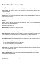
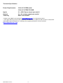
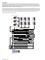
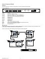
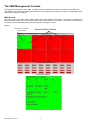
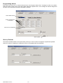
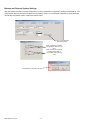
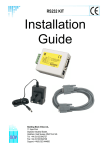
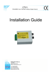
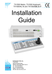
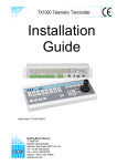
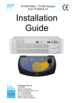
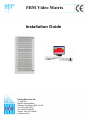
FBM Video Matrix
Installation Guide
Building
BlockBuilding
Video
Ltd.,
Building
Block
Video
Ltd.,
Building
Block
Block
Video
Video
Ltd.,Ltd.,
17 Apex17Park,
Building
Block
Video
Ltd.,
Apex17
Park,
17 Apex
Park,
Apex
Park,
Building
Block
Video
DiplocksDiplocks
Industrial
Estate,
17
Apex
Park,
Industrial
Estate,
Diplocks
Diplocks
Industrial
Industrial
Estate,
Estate,Ltd.,
17Sussex,
Apex
Park,
Hailsham,
East Hailsham,
Sussex,
BN27
3JU
UK.
Diplocks
Industrial
Estate,
Hailsham,
East
BN27
3JU
UK.
Hailsham,
East
East
Sussex,
Sussex,
BN27
BN27
3JU3JU
UK. UK.
Diplocks
Industrial
Estate,
Tel: +44(0)1323
842727
Hailsham,
East842727
Sussex,
BN27 3JU UK.
Tel: +44(0)1323
842727
Tel:
Tel:
+44(0)1323
+44(0)1323
842727
Hailsham,
Sussex, BN27 3JU UK.
Fax: +44(0)1323
842728
Tel:
+44(0)1323
842727
Fax: +44(0)1323
842728East
Fax:
Fax:
+44(0)1323
+44(0)1323
842728
842728
Tel:
+44(0)1323
842727
Support:Support:
+44(0)1323
444600
Fax:
+44(0)1323
+44(0)1323
444600842728
Support:
Support:
+44(0)1323
+44(0)1323
444600
444600
Fax: +44(0)1323
www.bbvcctv.com
Support:
+44(0)1323842728
444600
www.bbvcctv.com
www.bbvcctv.com
www.bbvcctv.com
Support: +44(0)1323 444600
www.bbvcctv.com
www.bbvcctv.com
Pre-Installation Checks and procedures
Unpacking
Check packaging – Upon delivery of the unit, inspect the packaging for signs of damage. If damage has occurred,
inform the carrier and or the suppliers immediately
Check Contents – After unpacking, check that all items are present. If any items are missing or damaged, contact
the equipment supplier.
Important Safety Precautions
Read Instructions – All relevant safety, installation and operating instructions should be read before attempting to
install, connect or operate the unit
Retain Instructions – All safety, installation and operating instructions should be retained for future reference.
Heed Warnings - All warnings on the unit and in any relevant safety, installation or operating instructions should be
adhered to.
Cleaning- Switch off and unplug the unit from the power outlet before cleaning. Do not use liquid cleaners or
aerosol cleaners. Use a damp cloth for cleaning.
Attachments – Do not use attachments which are not recommended by the product manufacturers as they may
cause a hazard or damage the unit.
Water and Moisture - Do not expose this unit to water or damp.
Installation and mounting – Only install the unit in a suitable enclosure or mount.
Power Sources – This unit should only be operated from the type of power source indicated in the manufacturer’s
label. I you are not sure of the type of power supply you intend to use, consult your equipment dealer or local power
company. For units intended to operate from battery power or other sources, refer to operating instructions.
Object and liquid entry – Never push objects of any kind into the unit, as they may touch dangerous voltage points
or short out parts that could result in fire or electric shock. Never spill liquid of any kind on or inside the unit.
Servicing – Servicing of the unit should only be undertaken by qualified service personnel, as opening or removing
covers may expose you to dangerous voltages or other hazards.
Damage Requiring Service – Servicing by qualified personnel should be carried out under the following conditions:
(a)
(b)
(c)
(d)
(e)
When the power supply cord or plug is damaged.
If liquid ha been spilled, or objects have fallen into the unit.
If the unit does not operate normally by following the operating instructions.
If the unit has been dropped or the enclosure is damaged.
If the unit indicates a distinct change in performance.
Replacement Parts – If replacement parts are required, ensure that only replacement parts recommended by the
product manufacturer are used.
Safety Check – Upon completion of any service or repairs to the unit, safety checks should be performed to ensure
that the unit is in proper operating condition.
Coax Grounding – If an outside cable system is connected to the unit, be sure the cable system is properly
grounded.
Adhere to safety standards – All normal safety precautions as laid down by British Standards and the Health and
Safety at Work Act should be observed.
FBM Manual V4.doc
-1-
Technical Specification
Power Requirements
12Vdc 6.7A FBM matrix
12Vdc 6.7A FBM CPU MK2
Inputs
16 – 4096 Camera inputs per matrix*
Outputs
16 – 64 monitor outputs per matrix*
Telemetry
BBV 2-wire RS485**
* Please contact BBV Technical support ([email protected]) for configuration options
** Third party telemetry protocols are supported by the FBM matrix if a BBV star card converter is used please
contact BBV Technical support for a complete list of supported protocols or visit our web-site.
http://www.bbvcctv.com
FBM Manual V4.doc
-2-
Description
The FBM is a video matrix and telemetry control system offering control of up to 4096 cameras from 8 control /
operator positions and capable of supporting up to 64 monitor outputs. BBV RS485 telemetry is employed as the
standard protocol. This will provide control for RX45X and RX55X telemetry receivers. Other RS485 protocols are
supported if a BBV Star card converter is used. Up-The-Coax telemetry can also be supported by the inclusion of a
coaxial telemetry interface (CTI Card) in the system design.
In order to simplify RS485 site wiring, a star-card should be used. This will provide 8 RS485 telemetry ports, each
port will support up to 32 cameras. The inclusion of a star-card in the system design also provides a degree of fault
tolerance, for example if a cable connected to a telemetry port should fail, control of the cameras connected to that
port only will be affected, all other cameras connected to the system should continue to operate as normal.
Figure1. Basic System Telemetry Wiring
Rx55X Address 7 Termination On
Dome Address 4 Termination Off
Rx55X Address 3 Termination On
Dome Address 5 Termination Off
Rx55X Address 2 Termination Off
Rx55X Address 1 Termination Off
Dome Address 6 Termination On
Third Party RS485 Telemetry
BBV RS485 Telemetry
BBV RS485 Telemetry
Star 1
Star 2
Star 3
Star 4
Star 5
Star 6
Star 7
Star 8
Master
BBV Starcard
Star 1
Star 2
Star 3
Star 4
Star 5
Star 6
Star 7
Star 8
Master
BBV Star card
Convertor
ALARM INPUT 1-8
12Vdc
OUTPUTS
ALARM INPUT 9-16
FBM CPU
RJ45 Patch Lead
BUILDING BLOCK VIDEO LTD
+44 (0) 1323 444600
www.bbvcctv.com
B-BUS PORT
1
2
3
4
5
6
7
8
9
10
11
1
2
3
4
5
6
7
8
9
10
11
12
12
13
13
14
14
15
15
16
STATUS
BBV SUPPLY ONLY
7VDC 4A MAX
16
VIDEO INPUTS
FB Matrix
17
18
19
20
21
22
23
24
25
26
27
28
29
30
31
32
VIDEO INPUTS
33
34
35
36
37
38
39
40
41
42
43
44
45
46
47
48
VIDEO INPUTS
RJ45 Patch Lead
FBM Manual V4.doc
-3-
System Component Details
FBM CPU
The CPU is the main controller for the system the connector details are shown below
Figure 2. FBM CPU
5V
@4 Amp ComA
Power
Com A
Com B
Com C
Com D
Com E
Com F
Com G
Com H
Com 1
USB
KBD
SVGA
NET
ComB
ComC
ComD
ComE
ComF ComG
ComH
SVGA
NET
Com1
KBD
USB
+5V DC
Keyboard or BBUS interface
Alarm Port 1, Alarms 1 – 256 via TX1500/AL16
Alarm Port 2, Alarms 257 – 512 via TX1500/AL16
Matrix Control Port via RS485 (RJ45) patch lead
Telemetry Port
Telemetry Port
Telemetry Port
Telemetry Port
Serial Alarms
USB – Serial converter for modem
Y-Piece connecting system management keyboard and mouse
SVGA system management monitor
Not implemented
BBV Starcard
A star card will normally be required in a system where telemetry is employed. Usually it will not be feasible to wire
the telemetry in a daisy-chain fashion see examples below.
Figure 3. Direct Daisy chain telemetry wiring example (Not Recommended)
PTZ Address 3
Un-terminated
PTZ Address 4
Un-terminated
PTZ Address 2
Un-terminated
PTZ Address 5
Un-terminated
PTZ Address 6
Un-terminated
Building 4
PTZ Address 7
Un-terminated
PTZ Address 8
Terminated
Building 2
BBV RS485 Telemetry
Building 3
PTZ Address 1
Un-terminated
Building 1
FBM CPU
FBM Manual V4.doc
-4-
As can be seen from figure 3, direct daisy chained telemetry is not a practical solution. The cable lengths can rapidly
become excessive (maximum allowable cable length = 1200m) and the labour cost to implement this option will be
significant. A much better solution is shown in figure 4 below which shows the same system wired utilising a star
card.
Figure 4.
PTZ Address 3
Terminated
PTZ Address 4
Terminated
PTZ Address 2
Un-terminated
PTZ Address 5
Un-terminated
Building 3
Building 4
PTZ Address 1
Terminated
PTZ Address 6
Terminated
PTZ Address 7
Un-terminated
PTZ Address 8
Un-terminated
Building 1
Building 2
Star 1
Star 2
Star 3
Star 4
Star 5
Star 6
Star 7
Star 8
Master
BBV Starcard
FBM CPU
BBV Starcard Converter
This device offers the same connectivity options as the star card, but in addition, performs a protocol conversion to
allow third party domes and telemetry receivers to be used with an FBM system. Only one protocol can be
supported on each star card converter. The protocols are selectable via internal dip switches please refer to the
BBV starcard manual for available protocol options.
FBM Manual V4.doc
-5-
Alarm Input Card
Each alarm card has 16 inputs. A total of 32 alarm cards may be installed on a system (512 individual alarms). The
alarm cards may be incorporated into the matrix sub-rack, installed in a separate sub-rack or supplied in an
individual 1U box. Figure 5 illustrates how to set the alarm card to a required address range.
Figure 5.
ALARM INPUT 1-8
ALARM INPUT 9-16
OUTPUTS
B-BUS 12Vdc
SW1
BBUS
Card 2 alarm 17-32
ON
Card 3 alarm 33-48
ON
Card 4 alarm 49-64
ON
1 2 3 4 5 6 7 8
1 2 3 4 5 6 7 8
1 2 3 4 5 6 7 8
1 2 3 4 5 6 7 8
Card 5 alarm 65-80
Card 6 alarm 81-96
Card 7 alarm 97-112
Card 8 alarm 98-128
ON
ON
ON
ON
1 2 3 4 5 6 7 8
1 2 3 4 5 6 7 8
1 2 3 4 5 6 7 8
1 2 3 4 5 6 7 8
FBM CPU Com B
Card 1 alarm 1- 16
ON
Switches 7&8 = Termination. Only terminate the last card on the bus
Card 10 alarm 145-160 Card 11 alarm 161-176
Card 12 alarm 177-192
ON
ON
ON
ON
1 2 3 4 5 6 7 8
1 2 3 4 5 6 7 8
1 2 3 4 5 6 7 8
1 2 3 4 5 6 7 8
Card 13 alarm 193-208
Card 14 alarm 194-224
Card 15 alarm 195-240 Card 16 alarm 240-256
ON
ON
ON
ON
1 2 3 4 5 6 7 8
1 2 3 4 5 6 7 8
1 2 3 4 5 6 7 8
1 2 3 4 5 6 7 8
Switches 7&8 = Termination. Only terminate the last card on the bus
FBM Manual V4.doc
-6-
FBM CPU Com C
Card 9 alarm 129 - 144
Keyboard Connection Details
Figure 6 below shows a typical keyboard arrangement. The FBM is capable of supporting up to 8 individual
keyboards.
Figure 6
FBM CPU
RJ45 Patch Lead
2m MAX
9-12Vdc
PSU
RJ45 Breakout Box
Connection Detail
5
4
6
3
7
2
8
1
RJ45 Patch Lead
2m MAX
1: +9-12Vdc
2: +9-12Vdc
3: RxA
4: TxA
5: TxB
6: RxB
7: 0v Screen
8: 0v Screen
RJ45 Patch Lead
2m MAX
9-12Vdc
PSU
Keyboard 2 Dip Switch
Keyboard 1 Dip Switch
ON
ON
1 2 3 4 5 6 7 8
1 2 3 4 5 6 7 8
Keyboard Program Button
Enabled
Termination On. Last device on bus only
Keyboard Program Button Disabled
Keyboard Address DIP Switch Settings
Keyboard 1
Keyboard 3
Keyboard 2
Keyboard 4
ON
ON
ON
ON
1 2 3 4 5 6 7 8
1 2 3 4 5 6 7 8
1 2 3 4 5 6 7 8
1 2 3 4 5 6 7 8
Keyboard 6
Keyboard 5
Keyboard 8
Keyboard 7
ON
ON
ON
ON
1 2 3 4 5 6 7 8
1 2 3 4 5 6 7 8
1 2 3 4 5 6 7 8
1 2 3 4 5 6 7 8
SW1 Assignment
ON
1 2 3 4 5 6 7 8
1-5 : Address
6+7 : RS485 Termination
8 : Keyboard Program Button Enable
FBM Manual V4.doc
-7-
The FBM Management Console
To simplify the configuration of the FBM, an SVGA monitor, keyboard and mouse is connected to the FBM CPU.
This allows access to all of the system parameters which are required to configure the system. The following section
outlines the configuration options.
Main Screen
The main screen of the CPU shows system status and simple diagnostic information. The screen is divided into 8
keyboard status panels and an alarm card status section at the bottom of the screen. If a keyboard is connected to
the system, the corresponding status panel will be green. See figure 7 below.
Figure 7.
Keyboard 1 Connected
(Green Panel)
Keyboard Status Panels
Alarm Card Status Indicators
Keyboard Status
FBM Manual V4.doc
-8-
Logging On
In order to configure the various options on the FBM, you must first log on to the system via the management
console. To log on simply click the logon button at the top of the screen and enter 6 x today’s date as a 4 digit
number into the dialogue box which will appear on the screen.
Configuring the system for operation
After logging onto the FBM, you will be able to access the system parameters via the system settings menu option.
Firstly, select the ‘System Setup’ Tab. This allows the number of cameras, monitors, alarms and PTZ mapping to be
set.
(The PTZ mapping section allows a telemetry receiver with a different address to the camera number to be
assigned. However, it is recommended where possible to match the PTZ address with the camera number.)
Changing the Password-Pin number
Select the Password Setup tab. Operator pass number can be added from here. The default pin is 9999. Press
Confirm Changes for the new PIN number to take effect.
FBM Manual V4.doc
-9-
Programming Alarms
Each alarm may have up to 4 actions these are set in the Program Alarms Tab. To assign an action to an alarm,
select the alarm number, then in the action fields, select the required action. The message can also be assigned to
an alarm, this is entered in the Alarm Information Text field.
Select Alarm Number
Select required action
for the alarm
Alarm text to be displayed
Click to update
Start-up Defaults
This tab set the default state of the system after power-up ie: which monitor is assigned to a particular keyboard,
and which camera is assigned to a particular monitor. Click update after every alteration.
FBM Manual V4.doc
- 10 -
Backup and Restore System Settings
After the system has been correctly configured, it is recommended the configuration settings are backed up. The
configuration data may be saved to either the CPU itself (Local) or to a removable USB memory stick (External).
The backup and restore option screens are shown below
Click to open Backup/
Restore Options
Click to backup or restore
Configuration data to local
CPU
Click to backup or restore
Configuration data to
removable USB memory
stick
Confirmation screen
FBM Manual V4.doc
- 11 -
Sequence Setup
One sequence may be assigned to each monitor connected to the system, with up to 1024 steps in each sequence.
Firstly open the Sequence Setup tab and select the required monitor for the sequence. Next check the box to the left
of the camera number required in the sequence, click add selected. If all of the cameras are required in the
sequence, click the Add ALL button. If an incorrect camera is selected in the sequence, all of the cameras within the
sequence will have to be removed by clicking Remove ALL, and re-entered from the beginning. Finally set the
required dwell time from the drop down box.
Select Monitor
Select Cameras to be included
in sequence
Choose appropriate action
Set Dwell Time
Camera Restrictions
The camera restrictions option, allows camera viewing and control to be restricted to specified monitors and
keyboards. By default all cameras can be controlled by all attached keyboards and viewed on any monitor.
Select Camera
FBM Manual V4.doc
Select Keyboards
- 12 -
Select Monitors
Monitor Restrictions
This option prevents the selected keyboards from switching cameras to specified monitors.
Select Keypad
Select Monitors
Camera Titles
This option allows the individual title of the camera to be edited. The text will be displayed on the monitor along with
the camera image. The maximum number of characters allowed is 15.
Select Camera Range
Edit camera titles
Click to update
FBM Manual V4.doc
- 13 -
Other BBV products.
Product
TX300
TX400
TX400DC
TX1000 MK2
TX1500
FBM range
RX100
RX100/BAX
RX200
RX300
RX400P
RX400DC
RX45X (AC)
RX55X (DC)
Multi RS485 protocol
and BBV up-the-coax
telemetry receivers
CTI16
STARCARD
STARCARD/CONVERTER
ACCESSORIES
FBM Manual V4.doc
Description
Single camera desktop telemetry transmitter with BBV up-the-coax & 20mA
telemetry, Pan/Tilt/Lens & Lights
As TX300 inc Wash, Wipe, Autopan, 8 presets, preset patrol.
As TX400 including joystick for proportional Pan/Tilt control.
8 or 16 camera, 2 monitor telemetry transmitter. Up to 2 keyboards. BBV up-thecoax and RS422 standard with options for alarm inputs and 20mA telemetry.
Mid size matrix 16 – 96 camera, 8 monitor. Up to 4 control positions
(keyboard & remote control) options for alarms, remote control, BBV upthe-coax and RS485 telemetry.
Large size matrix. Configurable up to 4096 cameras and 64 monitor outputs. Up to
16 control positions (keyboard & remote control) options for alarms, remote
control RS485/RS422 telemetry with various options. Please call to discuss
requirements.
Dome Interface with options to drive a large library of dome cameras. BBV up-thecoax and 20mA telemetry.
Dome Interface with options to drive a large library of dome cameras.
BAXALL up-the-coax telemetry.
AC receiver for Pan only heads or static cameras, Wash/Wipe/Lights. BBV up-thecoax and 20mA telemetry.
AC receiver for Pan/Tilt/Zoom/Focus/Iris Override and 1 Auxiliary output. BBV
up-the-coax and 20mA telemetry.
AC full function receiver. PTZFI 4 Auxiliary outputs, 16 presets. BBV up-the-coax
and 20mA telemetry.
24Vdc high/variable speed receiver. 16 presets, 8 local alarm inputs, 3 Auxiliary
outputs. BBV up-the-coax and 20mA telemetry.
Multiple RS485/422 and BBV up-the-coax controllable AC and DC receivers.
These receivers are controlled from an expanding range of serial protocols as listed
below. 110/230Vac supply. PTZFI, 64 presets, preset patrol, 8 local alarm inputs,
12V 500mA supply output. OSD for remote diagnostics. 3 Aux. outputs RX55X or
4 Aux. outputs RX45X.
Optional Privacy board.
BBV RS485, COAX & 20mA,
BAXALL COAX,
DENNARD RS485,
MOLYNX
PELCO P/D RS485,
VCL/HONEYWELL RS485,
PHILIPS/BOSCH RS485 (OPTIONAL BI-PHASE INPUT),
SENSORMATIC/AD RS422
VICON RS422
CIRRUS AUDIO MONITORING
Multi-protocol serial converter that gives up-the-coax control to 16 cameras. BBV
RS422, Dennard RS485, Pelco P, Pelco D, Philips/Bosch RS485/232, VCL
RS485, Sensormatic RS422, Molynx, Vicon
8 * RS485 output, 2 wire simples RS422, 4 wire full-duplex RS422, 2 wire halfduplex RS485.
Optional STARCARD/CONVERTER offering protocol conversion to drive an
increasing range of 3rd party protocols.
CTI/16 16 camera, RS422 to up-the-coax converter
TxLD (bidirectional RS422-RS232 converter)
98005 (bidirectional 20mA-RS232 converter)
AD RS422 (American Dynamics) protocol converters
- 14 -