1
THERMAL PRINTING SOLUTIONS
A630/A631/A632 PRINTER SERIES
USER MANUAL
Reference 3106894 Issue F
May 2005
AXIOHM
10, av Descartes
92350 Le Plessis Robinson
Tel : (33) 1 58 07 17 17 Fax : (33) 1 58 07 17 18
www.axiohm.com
EVOLUTIONS
Date
10/01
03/02
10/03
10/03
04/04
07/04
03/05
Issue
Z
A
B
C
D
E
F
Modifications
Creation
General update
Update : UL certification
Update : CE certification information and Bluetooth TM ; pages 7, 10 11 and 18
Update : UL verification
Modification of the Bluetooth TM password, page 24
Up date: To add A632 version
A630/A631/A632 Printer Series User Manual
Page 2 / 63
Reference: FDE 3106894 Issue F
INTRODUCTION
The purpose of the manual is to describe how to use the A630/A631/A632 thermal printer.
It also provides you with important information for safe printing
and for preventing problems and malfunctions.
Please read this manual before using the printer.
A630/A631/A632 Printer Series User Manual
Page 3 / 63
Reference: FDE 3106894 Issue F
CONTENTS
1
GENERAL OVERVIEW ...................................................................... 7
2
TECHNICAL SPECIFICATIONS....................................................... 8
2.1
Summary of technical specifications..................................................... 8
2.2
Physical specification............................................................................ 10
2.2.1
Dimensions ............................................................................. 10
2.2.2
Power supply specifications ................................................... 10
2.2.3
A632 version........................................................................... 12
2.3
Interface specifications......................................................................... 12
2.4
Environmental specifications............................................................... 12
2.4.1
Environmental conditions....................................................... 12
2.4.2
EMI, ESD and Safety ............................................................. 12
2.4.2.1
2.4.2.2
2.5
3
CE FCC C-tick
Safety
14
15
Operational performance..................................................................... 15
SETTING UP YOUR PRINTER ........................................................ 16
3.1
Getting ready to use the printer .......................................................... 16
3.1.1
Unpacking the printer ............................................................. 16
3.1.2
Description of printer parts..................................................... 16
3.1.3
Buttons.................................................................................... 17
3.1.4
LED Indicator ......................................................................... 17
3.1.5
Cutter ...................................................................................... 17
3.1.6
Connectors (Plugging and connecting your printer) .............. 18
3.1.6.1
Installing the battery and connecting the interface
on portable version
3.1.6.2
Connecting the power supply and interface on portable
and desktop versions
3.1.6.3
Charging the battery (A631)
3.1.7
3.1.8
18
19
20
Mounting holes ....................................................................... 20
Sensors.................................................................................... 20
3.2
Choosing the proper location for your printer .................................. 20
3.3
Loading paper ....................................................................................... 21
3.4
Light indicator....................................................................................... 22
3.5
Connectors & cables ............................................................................. 22
3.5.1
Power connector ..................................................................... 22
3.5.2
Communications interface connectors ................................... 22
3.5.2.1
3.5.2.2
3.5.2.3
3.5.2.4
RS232 Serial Interface
PC → Board Connections
Centronics Interface
A632 Version (automotive 12V)
A630/A631/A632 Printer Series User Manual
Page 4 / 63
23
23
24
25
Reference: FDE 3106894 Issue F
3.5.2.5
3.5.2.6
4
Centronics timing
BluetoothTM interface
26
26
3.6
Self test description............................................................................... 26
3.7
Configuration menu description ......................................................... 27
3.7.1
How to enter ........................................................................... 27
3.7.2
How to move in the program .................................................. 27
3.7.3
How to adjust parameters ....................................................... 27
3.7.4
How to quit and save the program.......................................... 27
3.7.5
List of parameters that can be changed .................................. 28
3.8
Drivers.................................................................................................... 29
LIST OF CONTROL CODES ............................................................ 30
4.1
Command Summary for Emulation compatible DP1000. ................ 30
4.2
Command Summary for ESC/POS Emulation
(compatible WITH Epson)............................................................................. 31
5
COMMAND DESCRIPTION ............................................................. 33
5.1
Command conventions ......................................................................... 33
5.2
Command Summary for Emulation compatible DP1000. ................ 33
5.2.1
Reset commands ..................................................................... 33
5.2.2
Vertical positioning and print commands............................... 33
5.2.3
Horizontal positioning commands.......................................... 35
5.2.4
Print characteristics commands .............................................. 35
5.2.5
Font commands....................................................................... 37
5.2.6
Graphics commands ............................................................... 37
5.3
Command Summary for ESC/POS Emulation
(compatible WITH Epson)............................................................................. 38
5.3.1
Reset commands ..................................................................... 38
5.3.2
Vertical positioning and print commands............................... 39
5.3.3
Horizontal positioning commands.......................................... 40
5.3.4
Printer configuration............................................................... 41
5.3.5
Print characteristics commands .............................................. 41
5.3.6
Font commands....................................................................... 42
5.3.7
Graphics commands ............................................................... 45
5.3.8
Printer Status .......................................................................... 46
5.3.9
Bar code commands................................................................ 50
5.3.10
Flash Firmware Download Commands (RS232 and BluetoothTM
models only) .......................................................................................... 52
5.3.10.1
5.3.10.2
5.3.11
Firmware Download Sequence
Commands
52
53
Configuration commands ....................................................... 55
A630/A631/A632 Printer Series User Manual
Page 5 / 63
Reference: FDE 3106894 Issue F
6
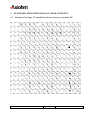
STANDARD AND INTERNATIONAL CHARACTER SET ......... 58
6.1
Standard: Code Page 437 (modified with euro character
at position D5) ................................................................................................. 58
6.2
7
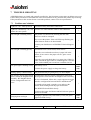
TROUBLE SHOOTING ..................................................................... 60
7.1
8
9
Additional codes.................................................................................... 59
Problems and solutions......................................................................... 60
CLEANING YOUR PRINTER........................................................... 61
8.1
Cleaning the printer.............................................................................. 61
8.2
Cleaning the print head........................................................................ 61
WARRANTY........................................................................................ 62
10 ACCESSORIES.................................................................................... 63
A630/A631/A632 Printer Series User Manual
Page 6 / 63
Reference: FDE 3106894 Issue F
1
GENERAL OVERVIEW
The A630, A631 and A632 are versatile ClamshellTM (Easy paper loading) thermal printers, designed for
desktop or portable use.
The A632 version is a version dedicated to automotive applications (taxis...).
By following the guide lines in this manual and with careful handling, a long and reliable operating life
can be expected from these printers.
Please note that portable versions are provided with uncharged batteries for safety and storage reasons.
Main features:
International character set
Automatic power-off features
Self-test facility
Graphics
Reset command
Emulation Choice
Bar Code Printing
User defined character set
A630/A631/A632 Printer Series User Manual
Page 7 / 63
Reference: FDE 3106894 Issue F
2
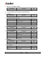
TECHNICAL SPECIFICATIONS
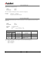
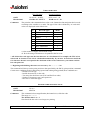
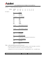
2.1 Summary of technical specifications
ITEM
Printing method
VALUE
UNITS
Static thermal dot line printing
-
TM
Paper loading
Clamshell
Number of resistor dots
-
384
-
Resolution
8
dots/mm
Printing width
48
mm
Printing speed
55 (desktop version) max
45 (portable version) max
mm/s
Character Fonts
16 x 24 dots. (24 columns)
or 9 x 24 (40 columns)
-
58 ± 0.1
mm
Paper width
Paper bucket diameter
50
mm
Data Buffer
4
K bytes
Thermistor
-
Opto-sensor
9 VDC or 110/240 with power supply
10.6 to 16
V
23
VA
110/240
50 - 60
V
Hz
1 sec. On, 6 sec. Off at 20° C
1 sec. On, 8 sec. Off at 50° C
°C
Head temperature detection
Paper empty detection
Printer voltage range: A630/A631
A632
Power consumption
Power supply
Maximum duty cycle
(in case of non-stop use)
Storage temperature range:
A630/A631
A632
-20 to 50
-20 to 70
°C
Operating temperature range
5 to 50
°C
Operating humidity
10 to 85
% RH (Non-Condensing)
Storage humidity
10 to 90
% RH (Non-Condensing)
Electrical life time
50
million head pulses per dot
Mechanical life time (abrasion)
50
Km
Over all
dimensions:
108
147
72
mm
mm
mm
330 or 600 (with battery)
g
Width
Depth
Height
Weight ( Without paper roll )
Recommended paper
TF50KSE3
-
80
µ
RS232 Serial
Centronics BluetoothTM
-
CE; FCC; C-tick ; UL / cUL; BluetoothTM
-
UL / cUL; IEC 60950
-
Maximum paper thickness
Interface
Certification:
EMI
Safety
A630/A631/A632 Printer Series User Manual
Page 8 / 63
Reference: FDE 3106894 Issue F
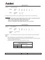
ITEM
Vibration:
COMMENTS
Sinusoïdal vibration tests
The standard used for this test was : IEC68-2-6
5-9 Hz, 6 mm displacement
9-200 Hz, 1g of accélération.
1 octave / minute
12 cycles per axis
3 axes
Printer unpacked and operating
Random vibration tests
The standard used for this test was : IEC 68-2-36
5-200 Hz, DSP : 0.01 g2/Hz
200-500 Hz, DSP : 0.003 g2/Hz.
mean acceleration : 1.7 g
Duration : 30min per axis
3 axes
Printer unpacked and operating
Shake vibration tests
The standard used for this test was : IEC 68-2-29
Wave : half sinusoidal
Acceleration : 15 g
Duration : 6 ms / 500 buffets
6 axes (±OX, ±OY, ±OZ)
A630/A631/A632 Printer Series User Manual
Page 9 / 63
Reference: FDE 3106894 Issue F
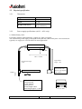
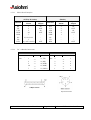
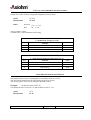
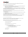
2.2 Physical specification
2.2.1
Dimensions
72 mm
108 mm
147 mm
330 g
600 g (with battery)
Height
Width
Depth
Weight (with cutter)
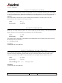
2.2.2
Power supply specifications (A630 – A631 only)
1) Without Battery Pack
For desktop models, without batteries, a supply of 9 VDC is required.
The current rating of the supply will depend on the print duty (More black print - more current) but
typically a 9v supply at 2.5A will suffice for most applications.
37+/-1 mm
103 +/-1 mm
Approximate
length : 1.8m
Approximate length
: 1.8m
To be connected to the
power network. The
connector type depends
on the country.
To be connected to the printer
11mm
+
-
DC-Jack Female connector –
5.5mm external
2.5 mm internal
Centre positive.
Overall length 50mm
Barrel length approx. 11mm.
A630/A631/A632 Printer Series User Manual
Page 10 / 63
64 +/-1 mm
Reference: FDE 3106894 Issue F
Remark: power supply 50 VA
•
•
INPUT
OUTPUT
:
:
Regulations :
230 VAC 50Hz
9VDC 2500mA
CE
UL
CSA
GS
Note: The power supply should be a “SELV” type in order to meet safety standards.
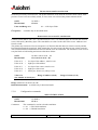
2) With Battery Pack
External, replaceable battery pack, AXIOHM reference 3106282 (Kit reference: 3106880).
Approximately 80m of text (25% pts on at 25°C) can be printed with a full battery.
It will take 1.30 hours (without printing) to totally charge the battery via the printer.
A optional power saving ("Power Mode") feature automatically switches the printer off when the interface
has not been used for 5 minutes period (Power mode = ON).
Caution: Danger of explosion if battery is incorrectly replaced. Replace only with the same or equivalent
type recommended by the manufacturer. Dispose of used batteries according to the manufacturer’s
instructions.
Specifications: Nickel-Cadmium rechargeable
Nominal Voltage
Rated Capacity
Average Weight
Maximum Volume
Terminals
Operating Temperature Range
6.0 V
1200 mAh
182 g (6.4 oz.)
78 cm3 ( 4.8 in.3 )
Flat
-20 °C to +50 °C
(-4 °F to 122 °F )
Important: AXIOHM cannot guarantee the correct operation of the printer if another power supply is
used other than an AXIOHM power supply.
A630/A631/A632 Printer Series User Manual
Page 11 / 63
Reference: FDE 3106894 Issue F
2.2.3
A632 version
The nominal voltage is 12V (operating range: 10.6V – 16V). To power the printer, use a cable able to
handle the max current value and protect the installation by using a 12V/10A max. fuse, suited for
automotive applications.
Note – Axiohm will not provide neither the cable nor the fuse.
2.3 Interface specifications
See chapter "Communications interface connectors".
2.4 Environmental specifications
2.4.1
Environmental conditions
Operating temperature:
Storage temperature: A630/A631
A632
Maximum humidity:
Vibration
Drop test
2.4.2
5 to 50 °C
-20 to 50 °C
-20 to 70 °C
10 to 90 % RH (non-condensing)
Details upon request : consult AXIOHM's Technical Support
Team.
The printer is packed.
1 meter on concrete
1 meter on wood
EMI, ESD and Safety
Conditions of acceptability:
EMI is measured using AXIOHM power supply adapter ref. 3106262. UL valid only if the proper power
supply (AXIOHM part n° 3106175) and the proper batteries (AXIOHM part n° 3106282) are used.
Note: The available replacement kits are:
ref. 3106935 A630/A631/A632 POWER SUPPLY KIT EU for the power supply
ref. 3106880 BATTERY KIT A631 for the batteries.
Safety recommendations: The power supply should be installed so it can be accessed in order to enable
power disconnection.
A630/A631 is designed to meet the requirements of:
CE
FCC
C-tick for Australia
UL / cUL
BluetoothTM (These products are in conformity with the 1999-5-CE directives.
A630/A631/A632 Printer Series User Manual
Page 12 / 63
Reference: FDE 3106894 Issue F
A certificate of compliance is available upon request from Axiohm.)
A632: automotive “e” marking. European directive 95/54/CE
A630/A631/A632 Printer Series User Manual
Page 13 / 63
Reference: FDE 3106894 Issue F
2.4.2.1
CE FCC C-tick
Note for Class A products only: This equipment has been tested and found to comply with the limits for
a Class A digital device, pursuant to Part 15 of the FCC Rules. These limits are designed to provide
reasonable protection against harmful interference when the equipment is operated in a commercial
environment. This equipment generates, uses, and can radiate radio frequency energy and, if not installed
and used in accordance with the instruction manual, may cause harmful interference to radio
communications. Operation of this equipment in a residential area is likely to cause harmful interference,
in which case the correction of the interference required will be at the user's expense.
Pursuant to Part 15.21 of the FCC Rules, any changes or modifications to this equipment not expressly
approved by AXIOHM may cause, harmful interference and void the FCC authorization to operate this
equipment.
Concerning products:
A630/A631
FCC, CE Class A
A630Yxxx
A631Yxxx
Y = all versions except where the fifth digit is 2
A630/A631
BluetoothTM
FCC Class B, CE Class B
A6302xxx
A6312xxx
FCC ID : RKAA631BT
Information to the user, for Class B products only:
The United States Federal Communications Commission (in 47 CFR 15.105) has specified that the
following notice be brought to the attention of users of this product:
This equipment has been tested and found to comply with the limits for a Class B digital device, pursuant
to part 15 of the FCC Rules. These limits are designed to provide reasonable protection against harmful
interference in a residential installation. This equipment generates uses and can radiate radio frequency
energy and, if not installed and used in accordance with the instructions, may cause harmful interference
to radio communications. However, there is no guarantee that interference will not occur in a particular
installation. If this equipment does cause harmful interference to radio or television reception, which can
be determined by turning the equipment off and on, the user is encouraged to try to correct the
interference's by one or more of the following measures:
Reorient or relocate the receiving antenna.
Increase the separation between the equipment and the receiver.
Connect the equipment into an outlet on a circuit different from that to which the receiver is
connected.
Consult the dealer or an experienced radio/TV technician for help.
The user may find the following booklet, prepared by the Federal Communications Commission, helpful:
How to Identify and Resolve Radio/TV Interference Problems. This booklet is available from the U.S.
Government Printing Office, Washington, D.C. 20402, Stock No. 004-000-00345-4.
Use of a shielded cable is required to comply within Class B limits of Part 15 of FCC Rules.
Pursuant to Part 15.21 of the FCC Rules, any changes or modifications to this equipment not expressly
approved by AXIOHM may cause, harmful interference and void the FCC authorization to operate this
equipment.
A630/A631/A632 Printer Series User Manual
Page 14 / 63
Reference: FDE 3106894 Issue F
2.4.2.2
Safety
UL / cUL
This printer is to be powered by a SELV circuit only.
The communication connectors must be of SELV type only.
2.5 Operational performance
Paper specification
Paper width
Maximum paper roll diameter
(Maximum paper roll length)
Recommended papers
Emulsion (sensitive) side
58 mm
50 mm
m (using 60gsm paper)
AXIOHM ref of KP 640
On outer side of roll
* You must contact AXIOHM if you wish to use an alternative type of paper; otherwise your warranty
might not be valid and you could cause damage to your printer.
A630/A631/A632 Printer Series User Manual
Page 15 / 63
Reference: FDE 3106894 Issue F
3
SETTING UP YOUR PRINTER
3.1 Getting ready to use the printer
3.1.1
Unpacking the printer
The printer comes in a plain cardboard carton with a reusable packing foam insert and separate pockets
for:
One printer
One set-up guide
One single 80m roll of thermal paper
One standard power supply (except A630/631xxxx - 500) for desktop versions
One power cable for connecting to the printer and to the power network, with appropriate
mains plug for the country of sale
One communication cable on portable versions
One battery on portable versions
The model number and serial number (including manufacturing week and batch number) of the printer will
be marked on the exterior of the packaging.
Make sure that no parts are missing or damaged. Report any deficiency to your supplier as soon as
possible after receiving the printer. The original packaging material should be kept to transport or return
your printer, if necessary.
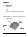
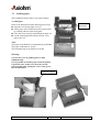
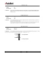
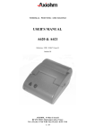
3.1.2
Description of printer parts
The A630 / A631 are complete printers designed with the ClamshellTM easy paper loading system.
A631 are portable versions, but can be used while connected to a power supply for battery charging.
Finger recesses
to open cover
Opening Cover
Tear bar
for paper cutting
" ON-OFF "
button
Paper feed button
A630/A631/A632 Printer Series User Manual
Page 16 / 63
Reference: FDE 3106894 Issue F
Rubber boot
It can be added to protect your printer for portable applications (A631). This protection is designed to be
easily attached to the user belt.
3.1.3
Buttons
Off
Paper feed
3.1.4
LED Indicator
Power On
Error
3.1.5
Cutter
Tear bar cutter
A630/A631/A632 Printer Series User Manual
Page 17 / 63
Reference: FDE 3106894 Issue F
3.1.6
Connectors (Plugging and connecting your printer)
Note: Connecting the interface is not applicable for BluetoothTM versions.
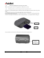
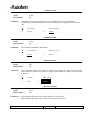
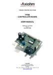
3.1.6.1
Installing the battery and connecting the interface on portable version
The battery is set underneath the printer as shown here after and clipped to the printer: push to clip, pull to
unclip.
A locating pin will prevent you from inserting the battery in the wrong direction.
If you feel any resistance when trying to clip the battery into place, verify that it is in the proper direction.
If not, turn the battery and try again.
Take care not to apply too much pressure while inserting the battery, as you might break the locating pin.
contacts
set & clip
Set your interface cable at the rear of the printer to the connector shown here after.
Connection for
RS232
communication
cable
A630/A631/A632 Printer Series User Manual
Page 18 / 63
Reference: FDE 3106894 Issue F
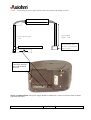
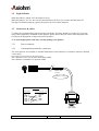
3.1.6.2
Connecting the power supply and interface on portable and desktop versions
A p p ro x im a te
le n g th : 1 .8 m
A p p ro x im a te le n g th
: 1 .8 m
T o b e c o n n e c te d to th e
p o w e r n e tw o rk . T h e
c o n n e c to r ty p e d e p e n d s
o n th e c o u n try .
T o b e c o n n e c te d to th e p rin te r
+
-
Desktop version:
Connect the interface
cable with the DB25
connector
Safety recommendation: The power supply should be installed so it can be accessed in order to enable
power disconnection.
A630/A631/A632 Printer Series User Manual
Page 19 / 63
Reference: FDE 3106894 Issue F
3.1.6.3
Charging the battery (A631)
When the battery is low, the green led flashes slowly. The printer stops when the battery is empty.
The charge begins when the printer is connected to the power supply: the green led flashes rapidly. When
fully charged, it stops automatically (charging time is about 1h 30 min).
Recommendation:
Never try to re-charge a full battery, you could damage it.
The charge cannot start if the cover is open or if there is no paper in the printer (red led
flashing).
When not using the printer for more than 24 h, unclip the battery from the printer. This will
prevent the battery from discharging.
Printing while charging the battery is possible, but the charge stops while printing
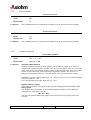
3.1.7
Mounting holes
Two (2) holes based underneath the printer under the rubber feet.
3.1.8
Sensors
The A630/A631 printer is fitted with two (2) sensors, which detect abnormal conditions:
Door-closed sensor:
End-of-paper (EOP) sensor:
3.2 Choosing the proper location for your printer
The A630/A631 printer may be used in a variety of applications; but, to maintain optimum working
conditions from your unit, the following recommendations should be followed:
Avoid dirty or dusty locations, the risk of water exposure, excessive heat or humidity
(temperature from 5 to 50°C for operating or -20 to 50 for storage) and mechanical stress.
Choose a stable level base on which to place the printer.
Make sufficient space around the printer to ensure comfort while using your printer,
including sufficient access to open the lid while changing paper.
It is recommended to avoid mechanical vibrations
A630/A631/A632 Printer Series User Manual
Page 20 / 63
Reference: FDE 3106894 Issue F
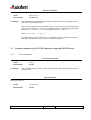
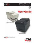
3.3 Loading paper
The ClamshellTM design allows easy paper loading.
To load paper:
Refer to the illustrations while following these steps:
Open the cover using finger recesses.
Set the paper roll as indicated on the picture below
by pushing aside the right roll support.
Close the cover leaving a small length of paper out.
Cut the small length left with the tear bar. Your
paper roll is set.
Roll setting
indications
Note:
The paper used should be recommended by AXIOHM
The paper width must be 58 mm
The maximum paper roll diameter is 50 mm
Warning:
1) Close the cover by pushing the two sides
simultaneously.
2) It is possible to load the paper when the printer
is powered (On). In this case, check if it is still
powered (On) after closing the cover; if not, press
the On/Off button.
right roll support
A630/A631/A632 Printer Series User Manual
Page 21 / 63
Reference: FDE 3106894 Issue F
3.4 Light indicator
When the printer is turned "off", the button is not lit.
When the printer is set "on", the "on-off" button flashes (red) for a few seconds, and then turns off.
The Paper feed button lights up (green); the printer can receive data and print.
3.5 Connectors & cables
To reduce the electromagnetic emissions and susceptibility, all cables should be screened. If you are not
using cables supplied by AXIOHM for this purpose, please ensure that your cables match the printer and
are rated at the appropriate voltage and current capacities.
*Use of an inappropriate cable may seriously damage your printer!
3.5.1
Power connector
3.5.2
Communications interface connectors
The A630 printers are available as standard with RS232 Serial interface or Centronics interface (desktop
version only).
The interface type is printed on the self-test slip.
The connector is a 25 way D socket for desktop model.
The connector is a Binder 5 for portable model.
Black cable
5 wires
100 cm ± 1 cm
PINOUT
DBF female
NC
RXD
TXD
DTR
GND
DSR
1
2
3
4
5
6
Binder 09-9790-71-05
1
2
3
4
5
MGND
TX
RX
DTR
CTS
Shield
Connector
DB9 female
A630/A631/A632 Printer Series User Manual
Page 22 / 63
Reference: FDE 3106894 Issue F
3.5.2.1
RS232 Serial Interface
A630
(25 Way D Socket)
A631
(Binder)
Function
Connector
Pinout
Input /
Output
Function
Connector
Pinout
Input /
Output
RX
TX
CTS
DTR
GND
NC
FG
RTS
3
2
5
20
7
6,8-19,21-25
1
4 (+10V via 1K)
IN
OUT
IN
OUT
OUT
RX
TX
CTS
DTR
GND
NC
FG
RTS
3
2
5
4
1
-
IN
OUT
IN
OUT
OUT
3.5.2.2
PC → Board Connections
A630
25 Way D Socket
Pins:
3
2
5
20
7
A631
→
→
→
→
→
→
PC
3 ( TX )
2 ( RX )
4 ( DTR )
6 ( DSR )
5 ( GND )
→
Binder
Pins:
3
2
5
4
1
→
→
→
→
→
PC
3
2
4
6
5
Ref. 09-9792-30-05-5
A630/A631/A632 Printer Series User Manual
Page 23 / 63
Reference: FDE 3106894 Issue F
3.5.2.3
Centronics Interface
630
( 25 Way D Socket )
Connector Pinout
Function
Input / Output
1
2
3
4
5
6
7
8
9
10
11
12
13, 14, 17
15
16
18 25
C_STROBE
D0
D1
D2
D3
D4
D5
D6
D7
C_ACKNO
C_BUSY
C_PE
NC
C_ERROR
C_INIT
GND
IN
IN
IN
IN
IN
IN
IN
IN
IN
OUT
OUT
OUT
/
OUT
IN
/
A630/A631/A632 Printer Series User Manual
Page 24 / 63
Reference: FDE 3106894 Issue F
3.5.2.4
A632 Version (automotive 12V)
Power:
-
A6320000: coaxial connector
A6320001: DB25 connector.
632
( 25 Way D Socket )
Connector Pinout
Function
Input / Output
1
2
3
4
5
6
7
8,9
10,11
12,13
14,15
16,17
18,19
20
21=>25
GND LOGIC
TXD
RXD
NC
CTS
NC
GND LOGIC
GDN POWER SUPPLY*
NC
+ POWER SUPPLY (12V)*
GDN POWER SUPPLY*
+ POWER SUPPLY (12V)*
NC
DTR
NC
/
OUT
IN
/
IN
/
/
/
/
/
/
/
/
OUT
/
* A6320010 version only.
A630/A631/A632 Printer Series User Manual
Page 25 / 63
Reference: FDE 3106894 Issue F
3.5.2.5
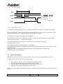
Centronics timing
Data
/Strobe
ta
tb
tc
/Ack
te
ta
tb
tc
te
time interval
Min
data setup time
0,5
strobe pulse width 0,5
data hold time
0,5
ack pulse w idth
2,5
500
all times in µs
Busy
3.5.2.6
Max
BluetoothTM interface
Uses internal antenna, therefore there is no communication interface connector for BluetoothTM model.
The A631 BluetoothTM model supports the Serial Port Profile, and it can be used as a serial printer, with
BluetoothTM being used in a cable replacement configuration, for example.
The interface is compatible with BluetoothTM standard V1.1.
Each printer has a specific User Name that will allow to address an identified printer amongst a batch.
This User Name is: A630- + "printer serial number".
A password is necessary to pair and access to the service and enable the connection.
This password is: 631200.
The maximum communication throughput is 115200 Baud.
The printer automatically goes in power save mode after 5 minutes without activity, and switches Off the
BluetoothTM link.
The printer needs to be manually turned On using the power On/Off button for BluetoothTM
communication to be re-established.
3.6 Self test description
Note: Before printing a first ticket on the portable version, you have to load the battery (see above)
To print a self test ticket, follow the next instructions:
•
•
•
•
If the printer is "On" set it "Off" by pushing the "ON/OFF" button.
Activate both the Paper feed button and the ON/OFF button.
Keep the paper feed button pressed and release the ON/OFF button.
When the ticket starts, release the Paper feed button.
When resetting the printer, all running operations are stopped and all information sent before resetting will
be lost.
A630/A631/A632 Printer Series User Manual
Page 26 / 63
Reference: FDE 3106894 Issue F
3.7 Configuration menu description
Program mode: The program switch may be accessed by keeping pressed the paper feed button during
the self test.
3.7.1
How to enter
To enter the program mode:
Power down the printer
Press the power button and the paper feed button together
Release the power button, keep the paper feed button pressed until the text “A630 configuration menu” is
printed.
3.7.2
How to move in the program
To move in the list of the parameters do a short click on paper feed button.
A long click allows selecting the parameter you want to change.
Then a short click allows you to move in the possible choices for that parameter. Do a long click to
validate the choice.
3.7.3
How to adjust parameters
For default parameters, see "Self test" chapter.
3.7.4
How to quit and save the program
When all the necessary changes to the parameters have been made, select the parameter “END” and
validate with a long click.
A new long click is asked, and then the printer has to be reset.
A630/A631/A632 Printer Series User Manual
Page 27 / 63
Reference: FDE 3106894 Issue F
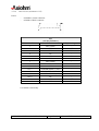
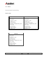
3.7.5
List of parameters that can be changed
Parameter (short click on paper feed)
Status
(1) Interface
RS232
BluetoothTM
(2) Graphics
Hi-Res
Standard
ESC_POS
1200 baud
2400 baud
4800 baud
9600 baud
19200 baud
38400 baud
57600 baud
115200 baud
No
Yes
(3) Baud Rate
(4) Parity
(5) Parity type
(6) Number of data bits
(7) Stop
(8) Protocol
(9) Brightness
(10) Emulation
Odd parity
Even parity
8 bit data
7 bit data
1
2
DTR/DSR
XON/XOFF
60-130
(not available with Bluetooth TM)
60 is lightest
130 is darkest
DP1000 / DP1200
ESC/POS
(11) Power Mode
ON
OFF
(12) Country
USA **
FRANCE
GERMANY
UK
DENMARK 1
SWEDEN
(13) Font set
16 * 24
9 * 24
A630/A631/A632 Printer Series User Manual
(only value allowed with BluetoothTM)
Page 28 / 63
(100 default)
ITALY
SPAIN
JAPAN
NORWAY
DENMARK 2
Reference: FDE 3106894 Issue F
3.8 Drivers
Function description for printer driving
Default settings:
A630000E
Data bits 8
Parity None
Baud Rate 115 200
Country U.S.A
Power mode Off
Emulation : Compatible ESC_POS
DTR / DSR
Font set 16*24
Graphics Standard
Brightness 100
A631xxxx
Data bits 8
Parity None
Baud Rate 115 200
Country U.S.A
Power mode On (5min)
Emulation : Compatible ESC_POS
DTR / DSR
Font set 16*24
Graphics Standard
Brightness 100
A632xxxx
Data bits 8
Parity None
Baud Rate 115 200
Country U.S.A
Power mode On
Emulation : Compatible ESC_POS
DTR / DSR
Font set 16*24
Graphics Standard
Brightness 100
A630/A631/A632 Printer Series User Manual
Page 29 / 63
Reference: FDE 3106894 Issue F
4
LIST OF CONTROL CODES
Hex Command
1F 01 n
Description
Page
55
select emulation
4.1 Command Summary for Emulation compatible DP1000.
Reset commands:
Hex Command
11
Description
Reset
Page
33
Vertical positioning and print commands:
Hex Command
Description
0A
Feed on line
0B
Form / Label feed
0C n
Vertical tab
0D
Carriage return
1B 33 n
Set line spacing
Page
33
33
34
34
34
Horizontal positioning commands:
Hex Command
Description
09
Horizontal tab
Page
35
Print characteristics commands:
Hex Command
0E
0F
15
18
19
1A
Double width
Single width
Underline "ON"
Underline "OFF"
Reverse print
Double height
Page
35
35
36
36
36
36
Font commands:
Hex Command
1C
1D
Description
24 Columns font
42 Columns font
Page
37
37
Graphics commands:
Hex Command
1B n d1 -> d24
1B 4B n1 n2
Description
Standard graphics
Epson graphics
Page
37
38
Description
A630/A631/A632 Printer Series User Manual
Page 30 / 63
Reference: FDE 3106894 Issue F
4.2 Command Summary for ESC/POS Emulation (compatible WITH Epson)
Reset commands:
Hex Command
Description
Page
1B 40
Initialize printer
38
1D FF
Printer reset
38
Vertical positioning and print commands:
Hex Command
Description
0A
Line feed
0C
Form feed
0D
Carriage return
1B 33 n
Set line spacing
1B 43 n
Set form length
1B 64 n
Print & feed
Page
39
39
39
34
40
40
Horizontal positioning commands:
Hex Command
Description
09
Horizontal tab
1B 24 n1 n2
Set print starting position
Page
40
40
Printer configuration commands:
Hex Command
Page
1F 74
Description
Print self-test
41
Print characteristics commands:
Hex Command
Description
1B 21 n
Set print mode
1B 7B n
Inverted printing
Page
41
41
Font commands:
Hex Command
1B 25 n
1B 26 s n m data
1B 52 n
Description
Set / Cancel user-defined characters
Define user-defined characters
Select international character set
Page
42
42
44
Graphics commands:
Hex Command
11 n1 … nl
1B 2A m n1 n2
Description
Graphic printing mode
Bit image graphics
Page
45
46
A630/A631/A632 Printer Series User Manual
Page 31 / 63
Reference: FDE 3106894 Issue F
Printer Status commands:
Hex Command
Description
Page
1B 76
Status request
46
1D 08
Read SRAM size
47
1D 49 n
Transmit printer ID
47
1D 49 40 n
Transmit printer ID, remote diagnostics
extension
48
1F 0A 84
Read voltage
49
1F 0A 85
Read print head temperature
49
1F 56
Return firmware revision
49
Bar code commands:
Hex Command
1D 48 n
1D 66 n
1D 68 n
1D 6B m d1…dk NUL
1D 6B m n d1…dn
1D 77 n
Description
Set HRI print position
Select HRI font
Set bar code height
Print bar code (mode 1)
Print bar code (mode 2)
Set bar code magnification
Page
50
50
50
51
51
51
Firmware downloads commands:
Hex Command
Description
1B 5B 7D
Switch to flash download mode
Page
53
1D 01
Return flash memory size
53
1D 02 nn
Select flash memory sector to download
53
1D 06
Get flash firmware CRC status
54
1D 07
Return boot sector CRC
54
1D 0E
Erase all flash contents except boot sector
54
1D 0F
Return main program flash CRC
54
1D 10 n
Erase selected flash sector
55
1D 11 al ah cl ch d1...dn
Download to active flash sector
55
Configuration commands:
Hex Command
Description
Page
1F 01 n
Select emulation
55
1F 02 n1..n6
Set communication parameters
56
1F 0B 4E 52 4A n
Print density
57
1F 0D 43 4C 45 n
Reset EEPROM
57
A630/A631/A632 Printer Series User Manual
Page 32 / 63
Reference: FDE 3106894 Issue F
5
COMMAND DESCRIPTION
5.1 Command conventions
The following information describes how each command is organized:
Command Name:
the ASCII control code
the Hexadecimal control code
ASCII
Hexadecimal
Comments
A descriptive name (not the ASCII code) used to identify the command.
A brief summary of the command, followed by more detailed information, if necessary.
5.2 Command Summary for Emulation compatible DP1000.
5.2.1
Reset commands
5.2.1.1.1
ASCII
Hexadecimal
Comments:
5.2.2
DC1
11
This command causes printer status reset. Printer status is set to single width, normal
height, and no underline. Note that the buffer remains unaltered to avoid any data loss.
Vertical positioning and print commands
5.2.2.1.1
ASCII
Hexadecimal
Comments:
FEED ONE LINE
LF
0A
This command prints and moves the printing position to the beginning of the next line.
If LF and CR are sent, the CR is ignored to avoid a double feed.
Ex:
⇒
41 41 41 41 41 0A 41 41 41
AAAAA
AAA
5.2.2.1.2
ASCII
Hexadecimal
Comments:
RESET
FORM / LABEL FEED
VT
0B
This command will feed 5 fast line feeds in normal mode.
A630/A631/A632 Printer Series User Manual
Page 33 / 63
Reference: FDE 3106894 Issue F
5.2.2.1.3
ASCII
Hexadecimal
Comments:
FF
0C n
This command fast feeds the paper by n lines where n is a single byte hex number in the
range 0 < n < 63. Note that a vertical tab will print the contents of the line buffer before
being executed.
5.2.2.1.4
ASCII
Hexadecimal
Comments:
VERTICAL TAB
CARRIAGE RETURN
CR
0D
This command prints the current line and feeds one line. If CR and LF are sent, the LF is
ignored to avoid a double feed.
On the receipt of the last printable character, the printer will automatically print the data
in the buffer. If CR and LF are sent after this condition, they will be ignored.
5.2.2.1.5
ASCII
Hexadecimal
SET LINE SPACING
ESC 3 n
1B 33 n
Comments:
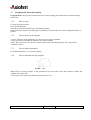
This command sets the line spacing to n/406 of an inch. Minimum line spacing is 7.5 lines
per inch. The line equals the character height when n < m (typical m = 27).
...…first printed line
m
….second printed line
A630/A631/A632 Printer Series User Manual
Page 34 / 63
Reference: FDE 3106894 Issue F
5.2.3
Horizontal positioning commands
5.2.3.1.1
ASCII
Hexadecimal
Comments:
5.2.4
HT
09
This command moves the printing position to the next horizontal tab position.
Tab stops occur at every 8th column. On receipt of this command, spaces are entered into
the line up to the next tab stop.
Ex:
09 41 41 41 41 41 41 41 41 41
⇒
_ _ _ _ _ _ _ _AAAAAAAAA
Print characteristics commands
5.2.4.1.1
ASCII
Hexadecimal
Comments:
DOUBLE WIDTH
SO
0E
This command turns double width printing on. This state continues until terminated by the
single width command or completion of the current line.
If the last character in the line buffer is double width but there is only room for a single
width character, then it will be printed in single width.
Ex:
41 41 41 41
⇒
AAAA
0E 41 41 41 41
⇒
5.2.4.1.2
ASCII
Hexadecimal
Comments:
HORIZONTAL TAB
SINGLE WIDTH
SI
0F
This command reverts to single width printing. Single and double width can
be combined anywhere on a line.
Ex:
0E 41 41 41 41
⇒
A630/A631/A632 Printer Series User Manual
0F 41 41 41 41
⇒
AAAA
Page 35 / 63
Reference: FDE 3106894 Issue F
5.2.4.1.3
ASCII
Hexadecimal
Comments:
NAK
15
Characters sent after this command will be underlined. Tabs are not underlined.
Underlining is terminated by the U/L release command or on completion of the current
line.
Ex:
41 41 41 41
⇒
AAAA
15 41 41 41 41
⇒
5.2.4.1.4
ASCII
Hexadecimal
Comments:
UNDERLINE OFF
This command Terminates underlining.
Ex:
15 41 41 41 41
⇒
AAAA
ASCII
Hexadecimal
18 41 41 41 41
⇒
AAAA
REVERSE PRINT
EM
19
This command sets the print to white on black. The command will toggle between reverse
and normal print wherever it appears on a line, but the condition is always reset at the end
of the line.
Ex:
41 41 41
⇒
AAA
19 41 41 41
⇒
5.2.4.1.6
ASCII
Hexadecimal
Comments:
AAAA
CAN
18
5.2.4.1.5
Comments:
UNDERLINE ON
AAA
DOUBLE HEIGHT
SUB
1A
This command Prints the line in double height for one line only.
Double height and single height cannot be mixed on the same line.
A630/A631/A632 Printer Series User Manual
Page 36 / 63
Reference: FDE 3106894 Issue F
5.2.5
Font commands
5.2.5.1.1
ASCII
Hexadecimal
Comments:
ESC
1C
This command selects 24 column fonts. Example: Sets 24 characters per line printing.
5.2.5.1.2
ASCII
Hexadecimal
Comments:
5.2.6
42 COLUMNS FONT
GS
1D
This command selects 42 column fonts. Example: Sets 42 characters per line printing.
Graphics commands
5.2.6.1.1
ASCII
Hexadecimal
Comments:
24 COLUMNS FONT
STANDARD GRAPHICS
ESC n d1 -> d24
1B n d1 -> d24
Standard 1000 Emulation
Graphics command to enter bit image printing. The number of graphic bytes sent will
depend on the column selection; example: 24 or 40. For each graphic byte sent, 6 bits out
of the 8 bits are used to build the graphics string (LSB as the right most dot) and 'n' is the
number of times the string will be repeated for a repetitive pattern. The value of 'n' is
limited to a maximum of 255 lines. The print buffer will be printed first if not empty.
Examples: To repeat a string of data bytes, d1....d24 over two rows for 24 column printing
send: 1BH, 02H, d1....d24.
For a non-repeated string send: 1BH, 01H, d1....d24.
High Resolution Graphics
To use this mode, there is an option in the set up for changing the default graphics: HIRES graphics.
This works in the same manner as the standard emulation but there are 48 characters
across the line, rather than 24 or 40.
1B n d1 -> d48
This provides full dot addressable graphics at 8 dots/mm and a true image of the data
received.
A630/A631/A632 Printer Series User Manual
Page 37 / 63
Reference: FDE 3106894 Issue F
5.2.6.1.2
ASCII
Hexadecimal
Comments:
EPSON GRAPHICS
ESC K n1 n2
1B 4B n1 n2
This command made possible by the higher resolution and memory capability of the
DP1200 over the standard 1000.
The number of graphic bytes is determined by n1 (low order byte) and n2 (high order
byte) by the equation: n2 + 256n1. For maximum graphics resolution of 384 printable
positions, n1 = 128 and n2 = 1. For 200 graphic bytes, n1 = 200, n2 = 0.
Note: 0 ≤ n1 ≤ 255,
0 ≤ n2 ≤ 1.
Each data character represents 8 dot rows of graphics, the LSB being the lowest dot.
The command and data must be sent for each line of graphics
5.3 Command Summary for ESC/POS Emulation (compatible WITH Epson)
5.3.1
Reset commands
5.3.1.1.1
ASCII
Hexadecimal
Comments:
INITIALIZE PRINTER
ESC @
1B 40
This command initialize printer. Clears the print buffer and resets the printer mode to
default values.
5.3.1.1.2
PRINTER RESET
Reboots the printer.
ASCII
Hexadecimal
GS (SPACE)
1D FF
A630/A631/A632 Printer Series User Manual
Page 38 / 63
Reference: FDE 3106894 Issue F
5.3.2
Vertical positioning and print commands
5.3.2.1.1
ASCII
Hexadecimal
Comments:
LINE FEED
LF
0A
This command prints and moves the printing position to the beginning of the next line.
If LF and CR are sent, the CR is ignored to avoid a double feed.
Ex:
⇒
41 41 41 41 41 0A 41 41 41
AAAAA
AAA
5.3.2.1.2
ASCII
Hexadecimal
Comments:
FF
0C
This command prints the current line and feeds the number of lines determined by using
the ESC C command.
5.3.2.1.3
ASCII
Hexadecimal
Comments:
CARRIAGE RETURN
CR
0D
This command prints the current line and feeds one line. If CR and LF are sent, the LF is
ignored to avoid a double feed.
5.3.2.1.4
ASCII
Hexadecimal
Comments:
FORM FEED
SET LINE SPACING
ESC 3 n
1B 33 n
This command sets the line spacing to n/406 of an inch. Minimum line spacing is 7.5 lines
per inch. The line equals the character height when n < m (typical m = 27).
first printed line
m
second printed line
A630/A631/A632 Printer Series User Manual
Page 39 / 63
Reference: FDE 3106894 Issue F
5.3.2.1.5
ASCII
Hexadecimal
Comments:
SET FORM LENGTH
ESC C n
1B 43 n
When used in conjunction with the form feed command (0Ch); the printer will feed n/2
under lines. Note that if n = 0 then there will be no line feeds. The default value is n = 0.
5.3.2.1.6
ASCII
Hexadecimal
Comments:
5.3.3
ESC d n
1B 64 n
This command prints the data in the print buffer and performs n line feeds.
Horizontal positioning commands
5.3.3.1.1
ASCII
Hexadecimal
Comments:
HORIZONTAL TAB
HT
09
This command moves the printing position to the next horizontal tab position.
Tab stops occur at every 8th column. On receipt of this command, spaces are entered into
the line up to the next tab stop.
Ex:
09 41 41 41 41 41 41 41 41 41
⇒
_ _ _ _ _ _ _ _AAAAAAAAA
5.3.3.1.2
ASCII
Hexadecimal
Comments:
PRINT & FEED
SET PRINT STARTING POSITION
ESC $ n1 n2
1B 24 n1 n2
This command sets the print starting position to the specified number of dots from the
margin. The range is from 0 to 384 where n2 is the high order byte (0 ≤ n2 ≤ 1) and n1 is
the low order byte.
(0≤n1≤255). The default condition is n1=n2=0 which positions print on the left margin.
The print position will always be rounded down to the nearest multiple of 8.
(Example: Print position 45 will be rounded down to 40.)
A630/A631/A632 Printer Series User Manual
Page 40 / 63
Reference: FDE 3106894 Issue F
5.3.4
Printer configuration
5.3.4.1.1
PRINT TEST FORM
This command will print the configuration settings ticket.
US t
1F 74
ASCII
Hexadecimal
Note: This command will assert busy and will ignore all input data until all tickets have been printed.
5.3.5
Print characteristics commands
5.3.5.1.1
ESC! n
1B 21 n
ASCII
Hexadecimal
Comments:
SET PRINT MODE
This command sets the print mode according to the following table and n is a single byte
in which each bit sets the printing function. Note that underlines cannot be used with a
horizontal tab and any combination of double height and width can be used. Double and
single height cannot be mixed on a line, however, whereas double and single width can be
mixed anywhere on a line.
Default is n = 0
Value
Bit
0
1
2
3
4
5
6
7
Function
Character Font
Undefined
Undefined
Undefined
Double-height
Double-width
Undefined
Underline
5.3.5.1.2
ASCII
Hexadecimal
Comments:
0
16 x 24
Cancelled
Cancelled
Cancelled
1
9 x 24
Set
Set
Set
INVERTED PRINTING
ESC {n
1B 7B n
When n = 1 then print is inverted and text will be printed from right to left. For normal
print n = 0. The default mode is set by the programmed parameters in the printer.
A630/A631/A632 Printer Series User Manual
Page 41 / 63
Reference: FDE 3106894 Issue F
5.3.6
Font commands
5.3.6.1.1
ASCII
Hexadecimal
ESC % n
1B 25 n
0≤n≤1
Range of n
Comments:
SET / CANCEL USER-DEFINED CHARACTERS
This sets or cancels the user defined character set.
Note: Once the user defined character set has been cancelled the default character set
will be loaded and the user defined characters will be lost.
0 => standard font used
1 => user-defined characters
5.3.6.1.2
ASCII
Hexadecimal
Comments:
DEFINE USER-DEFINED CHARACTERS
ESC & s n m data
1B 26 s n m data
[a[p] s x a]m-n+1
This allows the user-defined characters to be down-loaded:
Where:
- "s" specifies the number of bytes in the vertical direction. This value must be 3.
- "n" specifies the beginning ASCII code for the definition and "m" the final code.
If only one character is defined, use n = m. The range for n is 32 ≤ n ≤ m ≤ 255.
- "a" specifies the number of dots in the horizontal direction.
This value must be 16.
- "p" is the dot data for the characters. The dot pattern for a dots in the horizontal
direction from the left side.
The amount of data to be defined is s x a.
- After user-defined characters are defined once, they are available until another definition
is made or ESC % n is sent.
NOTE: See Ch "character cell structure".
The User defined character set (UDCS) and the standard character set are not available at
the same time.
Normally, the UDCS will be battery backed. However, if the batteries are left to discharge
completely, then the UDCS will be lost and the default character set will be loaded.
Example: (see next page)
If you want to define only the character 22h (HI-RES mode)
=> 1B 26 03 22 22 00 00 … … 3F 00 C0 7F 80 E0 … …
A630/A631/A632 Printer Series User Manual
Page 42 / 63
Reference: FDE 3106894 Issue F
P1 = 00H
P2 = 00H
P3 = 00H
P2
P3
01
02
03
04
05
06
07
08
09
10
11
12
13
14
15
16
17
18
19
20
21
22
23
24
P1
16 15 14 13 12 11 10 09 08 07 06 05 04 03 02 01
P4 = 00H
P5 = 00H
P6 = 00H
P7 = 3FH
P8 = 00H
P9 = C0H
P10 = 7FH
P11 = 80H
P12 = E0H
Organization of a user-defined character cell
A630/A631/A632 Printer Series User Manual
Page 43 / 63
Reference: FDE 3106894 Issue F
5.3.6.1.3
ASCII
Hexadecimal
Comments:
SELECT INTERNATIONAL CHARACTER SET
ESC R n
1B 52 n
The character set from the following table is determined by the value of n. The default
value is the character set programmed in the printer.
n
0
1
2
3
4
5
6
7
8
9
10
A630/A631/A632 Printer Series User Manual
Country
U.S.A.
France
Germany
U.K.
Denmark 1
Sweden
Italy
Spain
Japan
Norway
Denmark 2
Page 44 / 63
Reference: FDE 3106894 Issue F
5.3.7
Graphics commands
5.3.7.1.1
ASCII
Hexadecimal
1
Black
MSB
Comments:
0
White
GRAPHIC PRINTING MODE
DC1 n1… nl
11 n1… nl
1
Black
1
Black
0
White
0
White
1
Black
1
Black
LSB
This command specifies a single line of graphic data for 384 dots, the print zone for the
printer. The data is sent as 48 bytes, or 384 bits, representing the dots to be “on” or “off”.
Example:
11 0F 4C …………
1st printed line
2nd printed line
.
.
.
.
A630/A631/A632 Printer Series User Manual
Page 45 / 63
Reference: FDE 3106894 Issue F
5.3.7.1.2
ESC * m n1 n2 data
1B 2A m n1 n2 data
ASCII
Hexadecimal
Comments:
5.3.8
The bit image graphics command formats and prints a bit image depending on m, n1, n2
and the data..
All graphics are single density: m = 0.
n1, and n2 specify the number of bytes sent (data).
n2 is the high order byte ( 0 ≤ n2 ≤ 1 ), n1 is the low order byte ( 0 ≤ n1 ≤ 255). The total
number of data bits to send is calculated by the formula n2 x 256 + n1. For 384 graphic
bytes, the maximum per line, then n2=1, n1=128. The data (d) is formatted as shown
below.
Printer Status
5.3.8.1.1
ASCII
Hexadecimal
Comments:
BIT IMAGE GRAPHICS
STATUS REQUEST
ESC v
1B 76
The current printer status is transmitted to the host computer on receipt of this command.
It takes the form of a single byte with each bit representing a specific printer condition.
The conditions indicated are “true” when the bit is logic “1".
Bit
0
1
2
3
4
5
6
7
Paper out
Feeding paper
Lid open
Not used
Not used
Not used
Not used
Not used
The byte is sent regardless of the CTS handshaking signal.
A630/A631/A632 Printer Series User Manual
Page 46 / 63
Reference: FDE 3106894 Issue F
5.3.8.1.2
RETURN SRAM SIZE
Returns the size of SRAM on board
GS BS
1D 08
ASCII
Hexadecimal
The size (in number of 64 Kbytes sectors) is returned on a single byte.
Example:
SRAM size = 128 Kbytes,
the printer returns the hex value 02
5.3.8.1.3
TRANSMIT PRINTER ID
Transmits the printer model, type of version as defined below. This command is processed as normal
printer data.
GS I n
1D 49 n
ASCII
Hexadecimal
Operand:
Limit:
n = printer ID select
Decimal: n = 1; n = 49; 66 ≤ n ≤ 68
Hex:
n = 01; n = 31; 42 ≤ n ≤ 44
“GS I” OPERAND AND RETURNED STATUS DEFINITION
n
Value (hex)
Decimal
Hex
Printer ID
Function
1, 49
01, 31 Printer Model ID
A630
36
66
42
Manufacturer
AXIOHM
67
43
Printer Name
A630 or A631
68
44
Serial Number
Depends on serial
number
Note: for n = 66, 67, 68 the printer response is sent back in the following format:
Header = 5F (hex)
Data = ASCII string
NULL = 00 (hex)
A630/A631/A632 Printer Series User Manual
Page 47 / 63
Reference: FDE 3106894 Issue F
5.3.8.1.4
TRANSMIT PRINTER ID, REMOTE DIAGNOSTICS EXTENSION
Performs the remote diagnostic functions specified by n.
Each returned message is defined as:
n + data + <CR>
GS I @ n
1D 49 40 n
ASCII
Hexadecimal
Value of n
Refer to table
Value of n
Hex
Dec
20
32
Remote diagnostic item
Function
Serial #,
10 digit ASCII
Write to NVRAM
Example, send 14 bytes to printer:
GS I @ 0x20 1234567890
Write to NVRAM, and print on receipt to
verify
Example, send 14 bytes to printer:
GS I @ ! 1234567890
This will print on receipt:
Serial # written: 1234567890
Return Serial #, preceded by n to identify
Printer returns 12 bytes in above example:
#1234567890<CR>
21
33
Serial #
23
35
Serial #
A630/A631/A632 Printer Series User Manual
Page 48 / 63
Reference: FDE 3106894 Issue F
5.3.8.1.5
VOLTAGE AND TEMPERATURE MONITORING
Returns the results of latest voltage and temperature measurements.
US LF n
1F 0A n
ASCII
Hexadecimal
Limit:
Decimal: 132 ≤ n ≤ 133
Hex:
84 ≤ n ≤ 85
Always returns 7 Bytes:
Command ID + zero terminated ASCII string.
RETURNED STATUS DEFINITION
n = 0x84: Read Voltage (in Volt)
Function
Command Id
ASCII string
End of String
Byte
0
1-5
6
Byte
0
1-5
6
RETURNED STATUS DEFINITION
n = 0x85: Read Printhead Temperature (in °C)
Function
Command Id
ASCII string
End of String
5.3.8.1.6
Value
0x84
0x00
Value
0x85
0x00
SEND PRINTER SOFTWARE VERSION
The printer returns 8 bytes containing the boot and flash software version.
The first 4 bytes returned are an ASCII string for the boot version.
The second 4 bytes are an ASCII string for the flash version.
Example:
the printer returns 1.071.15
This means the boot version is 1.07 and the flash version is 1.15
ASCII
Hexadecimal
US V
1F 56
A630/A631/A632 Printer Series User Manual
Page 49 / 63
Reference: FDE 3106894 Issue F
5.3.9
Bar code commands
5.3.9.1.1
ASCII
Hexadecimal
Comments:
SET HRI PRINT POSITION
GS H n
1D 48 n
The range is 0 ≤ n ≤ 3.
The default value is n = 0 and”n” defines the print position as follows:
n = 0 not printed
n = 1 above the bar code
n = 2 below the bar code
n = 3 above and below the bar code
Guard patterns are not printed in the HRI text.
5.3.9.1.2
ASCII
Hexadecimal
Comments:
GS f n
1D 66 n
This command is used to define the size of the number under the bar code.
The range is n = 0 or 1 (default 0)
If n = 0, the 24 column font is selected.
If n = 1, the 40 column font is selected.
5.3.9.1.3
ASCII
Hexadecimal
Comments:
SELECT HRI FONT
SET BAR CODE HEIGHT
GS h n
1D 68 n
The range is 1 ≤ n ≤ 255 and n specifies the number of dots in the bar code height.
Default value is n = 162.
Note that if n = 0, the default height is used.
A630/A631/A632 Printer Series User Manual
Page 50 / 63
Reference: FDE 3106894 Issue F
5.3.9.1.4
PRINT BAR CODE
First Variation
ASCII
Hexadecimal
Comments:
Second Variation
GS k m d1…dk NUL
1D 6B m d1…dk NUL
GS k m n d1…dn
1D 6B m n d1…dn
The print bar code command selects a bar code, formats the data and prints the bar code
according to the variables m, n and d. The type of bar code is defined by “m” and valid
values are displayed in the table below.
m
0
1
2
3
4
5
6
7
Bar code types
UPC-A
*
UPC-E
*
EAN13
*
EAN8
*
CODE39
**
ITF
NOT ASSIGNED
CODE128
Mode
1
1
1
1
1
1
1
2
n is the number of digits, used in mode 2 only
d1..dk is the string of characters to be printed as the bar code.
* All of these bar code types use the last character as a checksum of. For example, the UPC-A bar
code needs 11 characters: the 12th is calculated automatically. If you enter 12 characters and if the
12th character doesn't correspond to the checksum of the 11 first characters, you cannot read the
bar code print out.
** Beginning and finishing characters are necessary: 2A … … … … 2A.
This command will always set the print position to that specified by the ESC $ (print position) command.
Certain error conditions result in data being ignored and nothing being printed, these conditions are:
- Invalid bar code type
- Invalid characters (d) in bar code
- Too many/few characters sent (UPC and EAN bar codes)
- Number of characters sent is not equal to m
- Bar code is wider than paper
5.3.9.1.5
ASCII
Hexadecimal
Comments:
SET BAR CODE MAGNIFICATION
GS w n
1D 77 n
This command selects magnification (horizontal size) of the bar code.
The range is 1 ≤ n ≤ 5.
The default value is n = 3.
Note that if the bar code is too longer, no printing.
A630/A631/A632 Printer Series User Manual
Page 51 / 63
Reference: FDE 3106894 Issue F
5.3.10
Flash Firmware Download Commands (RS232 and BluetoothTM models only)
These commands are used to load firmware into the printer.
There are two ways to enter the download mode.
1. While the printer is running normally, send the command, “Switch to Flash Download Mode (1B
5B 7D)” to leave normal operation and enter the download mode.
2. If the Flash if found corrupted during Level 0 diagnostics the download mode is automatically
entered after the printer has reset.
The printer never goes directly from the download mode to normal printer operation. To return to normal
printer operation either the operator must turn the power off and then on to reboot or the application must
send a command to cancel download mode and reboot.
When each flash download command is received, the printer returns either ACK or NAK to the host
computer when each command is received:
ACK (hexadecimal 06)
Sent when the printer has received a host transmission and has completed the request successfully.
NAK (hexadecimal 15)
Sent when a request is unsuccessful.
The commands are listed in numerical order according to their hexadecimal codes. Each command is
described and the hexadecimal, decimal, and ASCII codes are listed.
Communicates to the printer information downloaded from applications. Data is downloaded to flash
memory to query the state of the firmware, calculate the firmware CRC and other functions.
5.3.10.1 Firmware Download Sequence
By providing a set of low level commands, great freedom of implementation is given to customer
application to customize the sequence to match its specific requirements.
Following is the description of a typical Firmware download sequence.
Only the main steps are mentioned. Error checking and error recovery is not described:
1) Switch to Flash Download Mode
2) Check Flash Memory Size
3) Erase all Flash Memory sectors, except Boot Sector
4) Download Code to Active Flash Sector
4.1) Select Flash memory sector #n (each sector contains 64 Kbytes)
4.1.1) Program segment of N bytes
4.1.2) if more segments, loop back to 4.1.1)
4.2) if more sectors to program, loop back to 4.1)
5) Check Flash CRC
6) Reboot Printer
A630/A631/A632 Printer Series User Manual
Page 52 / 63
Reference: FDE 3106894 Issue F
5.3.10.2 Commands
5.3.10.2.1 SWITCH TO FLASH DOWNLOAD MODE
Puts the printer in flash download mode in preparation to receive commands controlling the downloading
of objects into flash memory. When this command is received, the printer leaves normal operation and can
no longer print transactions until the Reboot the Printer command (1D FF) is received or the printer is
rebooted.
This command does not affect the current communication parameters. Once the printer is in flash
download mode, this command is no longer available.
ESC [ }
1B 5B 7D
ASCII
Hexadecimal
5.3.10.2.2 RETURN FLASH MEMORY SIZE
Returns the size of the flash used. There are 4 sectors (64K each) in flash memory. This command assures
that the firmware to be downloaded is the appropriate size for flash memory.
GS SOH
1D 01
ASCII
Hexadecimal
The returned value corresponds to the highest sector number that can be accepted by the Select Sector to
Download (1D 02 nn) command:
03 = 256 Kbytes Flash
Exceptions:
Available only in download mode.
5.3.10.2.3 SELECT FLASH MEMORY SECTOR TO DOWNLOAD
Selects the flash sector (nn) for which the next download operation applies. The values of the possible
sector are restricted, depending upon the flash part type. The printer transmits an ACK if the sector
number is acceptable or an NAK if the sector number is not acceptable. Sector numbers start at 0
ASCII
Hexadecimal
Value and Range of n
GS STX nn
1D 02 nn
0-3 =
256k bytes Flash
Exceptions:
Available only in download mode.
A630/A631/A632 Printer Series User Manual
Page 53 / 63
Reference: FDE 3106894 Issue F
5.3.10.2.4 GET FLASH FIRMWARE CRC STATUS
Causes the printer to calculate the CRC for the Flash firmware code space and transmits the result.
This is performed normally after downloading completely a new firmware to verify that the downloaded
firmware is valid
The printer transmits ACK if the calculated CRC is correct; NAK if the CRC is incorrect
ASCII
Hexadecimal
GS ACK
1D 06
5.3.10.2.5 RETURN BOOT SECTOR CRC
Returns the CRC calculated over the boot sector code space.
ASCII
Hexadecimal
GS BEL
1D 07
Formulas:
ACK <low byte> <high byte>
5.3.10.2.6 ERASE ALL FLASH CONTENTS EXCEPT BOOT SECTOR
Causes the entire flash memory to be erased.
The printer returns ACK if the command is successful; NAK if it is unsuccessful.
ASCII
Hexadecimal
GS SO
1D 0E
Exceptions:
Available only in download mode.
5.3.10.2.7 RETURN MAIN PROGRAM FLASH CRC
Returns the CRC calculated over the flash firmware code space. The format of the response is ACK <low
byte> <high byte>.
ASCII
Hexadecimal
GS SI
1D 0F
A630/A631/A632 Printer Series User Manual
Page 54 / 63
Reference: FDE 3106894 Issue F
5.3.10.2.8 ERASE SELECTED FLASH SECTOR
Erases the previously selected sector. The printer transmits ACK when the sector has been erased. If the
previous sector is not successfully erased, or if no sector was selected, the printer transmits NAK.
GS DLE n
1D 10 n
ASCII
Hexadecimal
0-3 = 256k bytes Flash
Value and Range of n
Exceptions:
Available only in download mode.
5.3.10.2.9 DOWNLOAD TO ACTIVE FLASH SECTOR
Contains a start address (ah x 256 + al) and count (ch x 256 + cl) of binary bytes to load into the selected
sector, followed by that many bytes. The start address is relative to the start of the sector. Addresses run
from 0 to 64K.
The printer may return one of several responses. ACK means that the data was written correctly and the
host should transmit the next block. NAK means that, for some reason, the data was not written correctly.
This could mean that communications failed or that the write to flash failed. The alternatives seem to be to
retry the block or halt loading and assume a hardware failure.
GS DC1 al ah cl ch d1…dn
1D 11 al ah cl ch d1…dn
ASCII
Hexadecimal
Value of al
Value of ah
Value of cl
Value of ch
Value of d
=
=
=
=
=
low byte of the address , must be even
high byte of the address
low byte of the count , must be even
high byte of the count
data bytes, from 2 to n (always even)
Value of n
(for number of data bytes)
((ch * 256) + cl)
Range of Address (al ah)
Range of Count (cl ch)
0000-FFFE (hexadecimal)
0002-FFFE (hexadecimal)
Range: Addresses run from 0 to 64K.
Related Information: Available only in download mode.
5.3.11
Configuration commands
5.3.11.1.1 SELECT EMULATION
ASCII
Hexadecimal
Comments:
US SOH n
1F 01 n
This command is used to select the emulation.
n = 01 => ESC/POS emulation
n = 00 => DP1000 emulation
A630/A631/A632 Printer Series User Manual
Page 55 / 63
Reference: FDE 3106894 Issue F
5.3.11.1.2 SET COMMUNICATION INTERFACE PARAMETERS
Synopsis:
Setting communication parameters
Syntax:
ASCII:
Hex:
US
1F
STX
02
n1
n1
n2
n2
n3
n3
n4
n4
n5
n5
n6
n6
Description:
n1
00h
01h
04h
Interface
RS232
IEEE1284
BluetoothTM
n2, bit [0..2]
00h
01h
02h
03h
04h
05h
06h
07h
RS232 Baud rate
1200
2400
4800
9600
19200
38400
57600
115200
n2, bit 4
0
1
RS232 Number of stop bits
1
2
n2, bit 5
0
1
RS232 Number of data bits
8
7
n3
0x00
0x01
RS232 Parity
Odd parity
Even parity
n4
0x00
0x01
RS232 Parity mode
No parity
Enabled and set using parameter described above
n5
0x00
0x01
RS232 Handshaking
Xon/Xoff
DTR/DSR
n6
0x00
0x01
RS232 Parity Error Processing
Ignore
Print '?'
Notes: 1) This command is processed only in boot mode.
If the printer is running in normal mode, send first command “switch to Boot Mode” (1B 5B 7D).
2) This command must be followed by “Printer Reset”command (1D FF).
3) Parameters n2, n3, n4, n5, n6 are ignored, if n1 = 04h (BluetoothTM), or n1 = 01h (IEEE 1284).
A630/A631/A632 Printer Series User Manual
Page 56 / 63
Reference: FDE 3106894 Issue F
5.3.11.1.3 PRINT DENSITY
Synopsis:
Setting Print density
US
1F
VT
0B
Syntax:
ASCII:
Hex:
Limit:
Decimal:
70 ≤ n ≤ 150
Hex:
46 ≤ n ≤ 96
N
4E
R
52
J
4A
n
n
Description: Set the print density (energy applied to paper) in percent relative to nominal energy.
WARNINGS!!
Choose a print density setting no higher than necessary to achieve acceptable print density
Failure to observe this rule may result in a printer service call
Failure to observe this rule may void the printer warranty
Consult your AXIOHM technical support specialist if you have questions
5.3.11.1.4 RESET EEPROM
Synopsis:
Reset EEPROM
US
1F
Syntax:
ASCII:
Hex:
Operand:
Limit:
n = security byte
n=0
CR
0D
C
43
L
4C
E
45
n
n
Description:
This command will reset the non-volatile memory configuration items to their default
values.
Notes:
• This command must be sent while the printer is in its normal operating mode.
• Once the configuration parameters are downloaded to the printer using this command, the printer
must be reset before they take effect.
• Disabling the knife is not an option when a presenter is selected.
RESET EEPROM
OPERAND DEFINITION
n
Decimal
Hex
Reset
0
00
Reset EEPROM
A630/A631/A632 Printer Series User Manual
Page 57 / 63
Reference: FDE 3106894 Issue F
6
STANDARD AND INTERNATIONAL CHARACTER SET
6.1 Standard: Code Page 437 (modified with euro character at position D5)
A630/A631/A632 Printer Series User Manual
Page 58 / 63
Reference: FDE 3106894 Issue F
6.2 Additional codes
n
35D 36D 64D 91D 92D 93D 94D 96D 123D 124D 125D 126D
23H 24H 40H 5BH 5CH 5DH 5EH 60H 7BH 7CH 7DH 7EH
U.S.A.
0
#
$
@
[
\
]
^
`
{
France
1
#
$
a
°
ç
§
^
`
é
Germany
2
#
$
§
Ä
Ö
Ü
^
`
a
U.K.
3
£
$
@
[
\
]
^
`
{
Denmark 1
4
#
$
@
Æ
Ø
Å
^
`
æ
Sweden
5
#
¤
é
Ä
Ö
Å
Ü
é
Italy
6
#
$
@
°
\
é
^
Spain
7
Pt
$
@
i
Ñ
¿
Japan
8
#
$
@
[
¥
Norway
9
#
¤
é
Æ
Denmark 2
10
#
¤
é
Æ
A630/A631/A632 Printer Series User Manual
}
~
ù
è
"
ö
ü
ß
}
~
ø
å
~
ä
ö
å
ü
ù
à
ò
è
i
^
`
"
ñ
}
~
]
^
`
{
}
~
Ø
Å
Ü
é
æ
ø
å
ü
Ø
Å
Ü
é
æ
ø
å
ü
Page 59 / 63
Reference: FDE 3106894 Issue F
7
TROUBLE SHOOTING
AXIOHM printers are simple and generally trouble-free, but from time to time minor problems may occur.
Follow these procedures to determine the cause and resolution of any problems the printer may be having.
If the procedures in this section do not correct the problem, contact a service representative.
7.1 Problems and solutions
Lights are "off " when powered
Check the battery and cables connections.
Lights are continuously "on", but
printer does not operate
Check to see if the interface cable is well connected.
The red light is flashing slowly
The printer is in boot mode, meaning that the main
firmware could be corrupted.
/
/
Try to reset the printer. If the red LED keeps flashing, the
main firmware needs to be downloaded.
/
Contact your distributor or AXIOHM's Technical Support
team.
The red light is flashing quickly
Check that cover is well closed, if not close it.
Open the cover and make sure there is paper left in the
printer, if not: remove the paper roll core, place a new
paper roll.
/
Open the cover and check there is no paper jam, if there is
some: unwind the paper until no wrinkle appears, close the
cover with wrinkled part out and cut it with the tear bar.
The green light is flashing slowly
The battery is low.
Connect the power supply to charge the battery
Printing quality is deteriorating
The print-head may be getting dirty, see next chapter.
The interface board configuration
doesn’t match the daughter board
assembly : BT daughter board,
RS232 configuration and vice
versa
Check that the interface board configuration showed on
the diagnostics form matches the daughter board assembly.
A631
only
/
In case of mismatch, follow this 2 steps sequence to toggle
interface configuration between RS232 and BluetoothTM.
/
1/ Switch to boot mode: open the cover and reset the
printer while holding down the paper feed button.
The RED LED should blink slowly.
2/ Release the paper feed button and hold it down again for
at least 10 seconds.
Charging does not begin
Charging is possible only if the battery is low (the green
light must flash slowly)
A630/A631/A632 Printer Series User Manual
Page 60 / 63
A631
only
Reference: FDE 3106894 Issue F
Further details to solve eventual problems
If the print looks squashed
Check that the paper roll is sitting correctly in the paper
well and that the roll is the right way up. The paper should
be feeding off the bottom of the roll into the back of the
mechanism NOT off the top of the roll. Remove paper and
reload if necessary.
The printer prints “?” “!” or “*” in
place of the transmitted characters or it
does not action commands.
Check the handshaking line, parity setting and baud-rate.
The different characters denote particular errors: “?” parity error, “!” - framing error, “*” - over run error.
Note 1: in any case make sure you use thermal sensitive paper and that the paper roll is well set in its
bucket. Check that the sensitive layer of the paper is on the print-head side
Note 2: when resetting the printer, every running operation is stopped and all information sent before
resetting is lost.
8
CLEANING YOUR PRINTER
The A630/A631 printer is a highly reliable unit, which requires very little maintenance but will benefit
from cleaning as described in the next sections.
Before cleaning, unplug all electrical connections.
8.1 Cleaning the printer
Keep the external surfaces clean by wiping with a lightly damp cloth. Make sure that the inside surfaces
are kept dry at all times, and that the external surfaces are thoroughly dry before re-connecting.
8.2 Cleaning the print head
Depending of the environment in which the printer is used, the print head may accumulate dust. Therefore
it is necessary to clean it periodically in order to maintain a good print quality. The cleaning period
depends on the environment and the usage of the printer, but it should be cleaned at least once a year or up
to once a month in heavy-duty applications. The print head should always be cleaned immediately if the
print becomes visibly fainter due to contamination of the print head.
To clean the print head:
Switch the printer off.
Never clean the head immediately after printing, it may still be hot.
Open the cover of the printer and remove the roll of paper.
Clean the heating dots of the head with a cotton stick and a little alcohol solvent (ethanol, methanol or
IPA), but do not touch the print head with you fingers!
Allow the solvent to dry
Reload the paper and close the cover
Note: AXIOHM can also provide you with cleaning kits: reference n° CK60000A.
A630/A631/A632 Printer Series User Manual
Page 61 / 63
Reference: FDE 3106894 Issue F
9
WARRANTY
The printers or spare parts are guaranteed for a period of twelve (12) months, beginning at the delivery
date (ex-works).
The printers are guaranteed against defective material and/or workmanship. The warranty covers only, and
at AXIOHM’s choice, the cost of repair or replacement by AXIOHM in its factory, after restitution by the
customer of the printers or spare parts confirmed by AXIOHM to be defective (excluding assembling,
dismounting, shipping and other expenses).
The implementation of the warranty will not extend the warranty period.
Due to the complexity of the electronic and mechanical techniques used in the operation of such a printer,
AXIOHM does not warranty problems resulting from an installation not according to the published
specifications.
This warranty is subject to strict compliance with AXIOHM’s technical instructions for installation, use
and maintenance.
In particular, this warranty will not be valid for any defects due to:
•
•
•
•
Use of thermal paper other than those recommended by AXIOHM.
Incorrect maintenance.
Defective installation or modification not approved by AXIOHM.
Non-compliance, during any period, with the specified working conditions including the electrical
power supply specifications.
• Abnormal wear or mechanical damage, including dot burning due to power overloads.
• Transportation in packaging other than the type of carton / foam insert in which the printer was
originally packed.
• Any transportation, storage or setting up which does not comply with the technical specifications given
to the customer by AXIOHM, or its official distributor, will invalidate this warranty.
In no event shall AXIOHM assume any liability in excess of that defined above. It is agreed that
AXIOHM will not be liable for any indemnity for accidents to persons, damage to property or for loss of
earnings.
A630/A631/A632 Printer Series User Manual
Page 62 / 63
Reference: FDE 3106894 Issue F
10 ACCESSORIES
Reference
Designation
Contents
3105338
RS232 INTERFACE CABLE A631
Lot of:
For Products:
All A631
RS232 interface cable (x1)
A3107756
CARRY CASING
Lot of:
For Products:
All A631
Carry Casing (x1)
* See chapter "Description of printer parts"
3106880
BATTERY A631
Lot of:
For Products:
All A631
NiCd battery (x21)
A3107861
BLUETOOTH USB DONGLE with installation CD
(range: 100m)
Lot of:
For Products:
All A631 Bluetooth
(x1)
A630/A631/A632 Printer Series User Manual
Page 63 / 63
Reference: FDE 3106894 Issue F