1
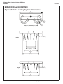
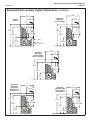
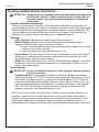
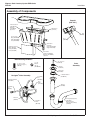
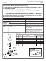
Installation EXD-2N Express® Deck Lavatory System EXD-Series (Standard and Wall-Hung Pedestals) Express® Decks are ADA and TAS compliant. Table of Contents Dimensions . . . . . . . . . . . . . . . . . . . . 2–3 Rough-Ins . . . . . . . . . . . . . . . . . . . . 4–5 Installation Instructions . . . . . . . . . . . 6–9 Cleaning and Maintenance . . . . . . . . . 10 Assembly of Components . . . . . . . . . . 11 Navigator® Valve Troubleshooting . . . 12 Navigator® Valve Repair Parts . . . . . . 13 IMPORTANT Read this entire installation manual to ensure proper installation, then file these instructions with the owner or maintenance department. Flush all the water supply lines before making connections. Debris in supply lines will cause the valves to malfunction. Turn OFF electrical power to the outlet when installing the Express® Deck. Wall anchors used must have a minimum pull-out rating of 1,000 lbs. Product warranties may be found under “Product Information” on our web site at www.bradleycorp.com. 215-1542 Rev. F; ECN 11-08-011 © 2012 Bradley Corporation Page 1 of 13 3/2/2012 P.O. Box 309, Menomonee Falls, WI 53052-0309 Phone: 800.BRADLEY (800.272.3539) Fax: 262.253.4161 bradleycorp.com Express® Deck Lavatory System EXD-Series EXD-2N Installation EXD-2N/STD and EXD-2N/WH Express® Deck Lavatory System Dimensions 50" (1270mm) 8" (203mm) Radius 15" (381mm) 15" (381mm) Standard Height 10" (254mm) Radius 7" (178mm) 21¼" (540mm) 30" (762mm) 36" (914mm) Wall-Hung Height 7" (178mm) 30" (762mm) 36" (914mm) 2 3/2/2012 Bradley Corporation • 215-1542 Rev. F; ECN 11-08-011 Express® Deck Lavatory System EXD-Series Installation EXD-2N Express® Deck Lavatory System Dimensions continued . . . 211⁄8" (537mm) 211⁄8" (537mm) Standard Height Wall-Hung Mounted at Standard Height 11½" (292mm) 34" (864mm) 11½" (292mm) 34" (864mm) 30" (762mm) 85⁄8" (219mm) 30" (762mm) 85⁄8" (219mm) 3" (76mm) 13¼" (337mm) 13¼" (337mm) Scuff Base Standard Height Only Wall-Hung Mounted at Juvenile Height Ages 6 through 12 211⁄8" (537mm) 11½" (292mm) 31" (787mm) 27" (686mm) 85⁄8" (219mm) 10¼" (260mm) Wall-Hung Mounted at TAS Height Grades Pre-K through 5 or 6 211⁄8" (537mm) 11½" (292mm) 30" (762mm) Wall-Hung Mounted at TAS Height Grades 6 through 8 or 9 211⁄8" (537mm) 11½" (292mm) 32" (813mm) 26" (660mm) 85⁄8" (219mm) 9¼" (235mm) Bradley Corporation • 215-1542 Rev. F; ECN 11-08-011 28" (711mm) 85⁄8" (219mm) 11¼" (260mm) 3/2/2012 3 Express® Deck Lavatory System EXD-Series EXD-2N Installation Installation Instructions Supplies required for installation: • (6) 3/8” wall anchors, bolts and 1” min. O.D. washers to mount main frame and bowl to wall (minimum pull-out rating of 1,000 lbs.) • STD. HEIGHT ONLY: (2) 3/8” wall anchors, bolts and 1” min. O.D. washers to mount scuff base to wall • 1/2” Nominal copper tubing for hot and cold supply piping • 1-1/2” NPT drain piping • 110 volt electrical outlet for optional 110/24 VAC plug-in transformer, if required • (2) #10 wall anchors and fasteners for optional Navigator valve mounting • 240/208-volt or 277-volt electrical box for optional electric tankless water heater Step 1: Rough in IMPORTANT: Dimensions shown in Figure 1 on page 5 are for a Standard and WallHung Pedestal Express® Deck only. Make sure to follow appropriate dimensions based on configuration and required rim height. See Charts 1 and 2 on page 5 before beginning rough-ins. 1.Rough in 1/2” nominal copper tubing for hot and cold supply lines through wall at dimensions shown. 2.Rough in 1-1/2” NPT drain waste connection through wall at dimensions shown. 3.FOR OPTIONAL ELECTRIC FAUCETS: Install the 110 volt GFCI electrical outlet per local code at the location shown in Figure 1. 4.Install four to six 3/8” wall anchors with a minimum pull-out rating of 1,000 lbs. (supplied by installer) at the locations shown in Figure 1. 5.On the back of the bowl, measure the distance between the 3/4” bowl mounting holes. Divide this measurement in half. Measure and mark this dimension on the wall to the left of the centerline and to the right of the centerline. Install two 3/8” wall anchors with a minimum pull-out rating of 1,000 lbs. (supplied by installer) at the locations marked (ref. location “A” shown in Figure 1). NOTE: Wall anchors at location “C” (standard frame only) do not require a minimum pull-out rating of 1,000 lbs. NOTE: The anchors will be used to mount the Express® Deck bowl and frame to the wall. 4 3/2/2012 Bradley Corporation • 215-1542 Rev. F; ECN 11-08-011 Express® Deck Lavatory System EXD-Series Installation EXD-2N EXD-2N Express® Deck Lavatory System Dimensions 23½" (597mm) 23½" (597mm) 13¼" (337mm) Option #1 93⁄8" (238mm) A Hot Supply Option #2** 93⁄8" (238mm) 3" (76mm) B D G G 32" (813mm) B D 4" (102mm) F A 4" (102mm) E Cold or Tempered Supply Option 28¾" (730mm) 13⁄8" B (35mm) 25¾" (654mm) B 2"(51mm) 20" (508mm) 13" (330mm) 21" (533mm) 22" (559mm) 15" (381mm) 19" (483mm) Floor Figure 1 C C * Option 1 - Recommended 240V/208V or 277V Electrical Box Location (4"L x 4"W x 8"H) or **Option 2 - Recommended 240V/208V or 277V Electrical Box Location (4"L x 4"W x 4"H) 3½" (89mm) CHART 1 RIM HEIGHT VERTICAL HEIGHT ADJUSTMENTS “A” THROUGH “F” FIXTURE STYLE 34” NONE STANDARD HEIGHT 34” NONE WALL HUNG 32” SUBTRACT 2” TAS, GRADES 6 THRU 8/9 31” SUBTRACT 3” JUVENILE HEIGHT 30” SUBTRACT 4” TAS, PRE-K THROUGH 5/6 CHART 2 CODE DESCRIPTION QTY. “A” 3/8” BOWL WALL ANCHORS WITH A MINIMUM PULL-OUT FORCE OF 1,000 LBS. 2 “B” 3/8” MAIN FRAME WALL ANCHORS WITH A MINIMUM PULL-OUT FORCE OF 1,000 LBS. 6 “C” 3/8” BASE FRAME WALL ANCHORS, STANDARD FRAME OPTION ONLY. 2 “D” 1/2” NOMINAL COPPER TUBING HOT/COLD SUPPLIES, STUB OUT 2” FROM WALL 2 “E” 1-1/2” NPT DRAIN, STUB OUT 2” FROM WALL 1 “F” 110V GFCI PROTECTED ELECTRIC OUTLET (FOR OPTIONAL ELECTRONIC FAUCETS) 1 “G” #10 WALL ANCHORS/FASTENERS FOR OPTIONAL NAVIGATOR VALVE MOUNTING 2 Bradley Corporation • 215-1542 Rev. F; ECN 11-08-011 ® 3/2/2012 5 Express® Deck Lavatory System EXD-Series EXD-2N Installation Installation Instructions continued . . . Step 2: Mounting frame to wall 1.Using a T20 Torx key, remove the six #10-24 flat head Torx screws and #10 finish washers securing the access panel to the main frame, and remove the panel (Figure 2). 2.Position the frame against the wall, ensuring that it is level. IMPORTANT: Anchoring the frame to a wall that is not flat may cause the frame to bend, making it difficult to reinstall the access panels. 3.Ensure that the back of the frame is flat against the wall. 4.Once you have positioned the frame such that it is level (and resting on the floor, standard height frame only) and flat against the wall, use the 3/8” bolts and 1” min. O.D. washers to mount the frame to the wall (Figure 3). 5.When mounting the standard height frame, mount the scuff base to the wall at the same time using the two additional 3/8” bolts and washers mentioned in Step 1, procedure #3 on page 4 (Figure 3). Main Frame Access Panel #10-24 Panel Fasteners and Washes (6) Places Scuff Panel (Standard Height Frame Only) Scuff Panel Fasteners and Washers (4) Places Figure 2 ⁄8" Wall Anchors (4) Places 3 * * Main Frame * * Scuff Base Frame (Standard Height Frame Only) * Figure 3 6 3/2/2012 ⁄8" Wall Anchors (2) Places (Standard Height Frame Only) 3 * Bradley Corporation • 215-1542 Rev. F; ECN 11-08-011 Express® Deck Lavatory System EXD-Series Installation EXD-2N Installation Instructions continued . . . Step 3: Installing bowl WARNING: To prevent serious injury and/or damage to the bowl, move and position the bowl with the assistance of another person and always use appropriate lifting procedures. NOTE: Refer to Figure 4 below when installing the bowl. 1.With someone to assist you, place the bowl squarely onto the frame. 2.Attach the front underside of the bowl to the frame using the two 1/4”-20 x 1/2” panhead screws and washers provided. Do not tighten bolts at this time. IMPORTANT: When bolting the bowl to the frame and wall, do not overtighten bolts. Overtightening bolts can damage the Terreon® material. 3.After the bowl is attached to the frame, use 3/8” bolts and 1” min. O.D. washers (supplied by the installer) to bolt the bowl to the wall anchors, two places. 4.Tighten the screws installed in procedure #2 above to secure the bowl to the frame. Do not overtighten. Figure 4 Bowl ¼"-20 Screws and Washers (2) Places Bowl/Frame Mounting Main Frame ⁄8" Bolt and Washer (2) Places for Bowl Mounting 3 Bradley Corporation • 215-1542 Rev. F; ECN 11-08-011 Scuff Base Frame and Drain Assembly Not Shown For Clarity 3/2/2012 7 Express® Deck Lavatory System EXD-Series EXD-2N Installation Installation Instructions continued . . . Step 4: Connecting supply and drain 1.Connect the Navigator® Thermostatic Mixing Valve as shown in Figure 5a. 2.Install the drain plug in the drain hole in the bowl (see Figure 5b). 3.Beneath the bowl, install the 1/8” rubber washer and the threaded tailpiece onto the drain plug. 4.Assemble the P-trap by connecting the 1-1/2” tubular pipe to the tailpiece and to the 1-1/2” drain pipe stubbed out of the wall (see Figure 5c). 5.Install the strainer on the drain plug opening inside the bowl using the #8 screw. Cold Supply Hot Supply ½" NPT (269-653) Stop Valve (S27-340) ½" Flexible Hose (269-2053) Navigator® Valve (S01-526) Navigator Bracket (140-1041) #8 Screw (160-447) Figure 5a #8 Screw Strainer Bowl P-Trap ⁄8" Rubber Washer 1 Strainer Drain Plug Tailpiece 45° Tailpiece Figure 5c Figure 5b 8 3/2/2012 Frame (Front) Bradley Corporation • 215-1542 Rev. F; ECN 11-08-011 Express® Deck Lavatory System EXD-Series Installation EXD-2N Installation Instructions continued . . . Step 5: Optional hot water heater WARNING: To avoid personal injury or damage to the unit when installing the water heater, make all plumbing connections first, then proceed with the electrical connections. NOTE: 240/208 or 277 voltage is required for hot water heater. Refer to the installation manual provided with the hot water heater for further installation information. 1.Remove the cover from the water heater. Attach the bracket to the cover with the two screws, nuts and washers, then reattach the cover (see Figure 6a). 2.Hang the water heater on the right side frame member (see Figure 6b). 3.Connect the 1/2” flexible hose from the cold water supply stub-out to the hot water heater inlet. 4.Connect the 1/2” flexible hose from the hot water heater outlet to the supply inlet on the solenoid valve assembly. Step 6: Completing installation 1.Install the faucets according to the installation instructions that came with your faucets. 2.Turn on the water supply to the Express® Deck and check for leaks. 3.FOR DECKS WITH INFRARED FAUCETS ONLY: Turn on the electrical power to the electrical outlet and pass your hand in front of each faucet’s sensor until all the air is purged from the lines and water is flowing smoothly. Bracket #8 Nut #8 Washer #8-32 x ¾" Round Head Machine Screw Water Heater Base Water Heater Cover Figure 6a Stop Valve Water Heater Inlet Cold Water Supply Outlet to Faucets Figure 6b Bradley Corporation • 215-1542 Rev. F; ECN 11-08-011 3/2/2012 9 Express® Deck Lavatory System EXD-Series EXD-2N Installation Installation Instructions continued . . . Step 7: Adjust the Temperature NOTE: This valve is NOT factory preset. Upon installation, the temperature of this valve must be checked and adjusted to ensure delivery of a safe water temperature. Water in excess of 110°F (43°C) may cause scalding. 1.Loosen the cap screw about ¼" (4–6 turns) and lift up the cover (do not remove). 2.Using the cover, turn the cartridge gently until desired water temperature is reached. Do not turn past stops as this may damage the unit. Push the cover down and tighten the screw. 3.After testing is complete, reinstall panel to frame. Fasten panel with eight Torxhead screws provided (see Figure 2 on page 6). 10 3/2/2012 H C Figure 7 Bradley Corporation • 215-1542 Rev. F; ECN 11-08-011 Express® Deck Lavatory System EXD-Series Installation EXD-2N Cleaning and Maintenance Instructions IMPORTANT: Strong alkaline or acid-based chemicals and cleansers should not be used to clean Terreon®. If these chemicals come in contact with the Terreon® surface, wipe off the surface immediately and flush with soapy water. Terreon® and panel maintenance The bowl is constructed of Terreon®, a densified solid surface material composed of an acrylic modified polyester resin. Terreon® is resistant to chemicals, stains, burns and impact. Surface damage can be easily repaired with everyday cleaners or fine grit abrasives. The panel is made of an acrylic/ABS laminate, and will not chip, peel or flake. With regular cleaning, your Terreon® fixture will provide years of dependable service. Cleaning • Daily Cleaning: Wipe the surface with a damp cloth and wipe dry. • Weekly Cleaning: Wipe the surface with a damp cloth and a household liquid detergent. Stubborn stains can be removed as follows: 1.Using a #7448 Scotch-Brite® pad, scrub with an abrasive cleanser such as Ajax®, Comet® or Soft Scrub® and water. 2.Clean thoroughly with soapy water and allow to dry. • Scorch Marks: Although Terreon® will not burn, a lit cigarette in contact with Terreon® could leave a scorch mark. Scorch marks can be removed by buffing with a #7448 Scotch-Brite pad or with an abrasive cleaner. • Repair kit: In the unlikely event your Terreon® surface becomes damaged, it can easily be repaired. Contact your Bradley representative to order a repair kit and be sure to specify color when ordering. Panel cleaning IMPORTANT: Do not use abrasive cleansers to clean the panel. Abrasive cleaners can mar the surface. • Graffiti/Vandalism: If vandals create markings on the panel, Bradley recommends using Motsenbocker’s LIFT OFF® to remove ink and spray paint. Remover #3 is for ink and markers, and Remover #4 is for spray paint. Motsenbocker’s LIFT OFF® can be ordered through Sanitary Maintenance Service Inc. (call 1-800-451-5523 x 425 or visit www.santitarymaintenance.com/product.htm for ordering information). After cleaning with LIFT OFF®, give the panel a final thorough cleaning with a liquid tub and tile cleaner to remove soil and maintain the glossy finish. NOTE: Use of brand names is intended only to indicate a type of cleaner. This does not constitute an endorsement, nor does the omission of any brand name cleaner imply its inadequacy. Many products named are regional in distribution and can be found in local supermarkets, department and hardware stores or through your cleaning service. It is emphasized that all products should be used in strict accordance with package instructions. Bradley Corporation • 215-1542 Rev. F; ECN 11-08-011 3/2/2012 11 Express® Deck Lavatory System EXD-Series EXD-2N Installation Assembly of Components Bowl Prepack (S45-2731) Panel Fasteners (160-450) Washers (142-002CA) (6) Places Main Frame (S17-325) Stop (S27-340) Access Panel Gray (186-1646) Putty (186-1646A) Coal (186-1646B) Hose (269-2053) Scuff Frame (S17-326) Used with Standard Height Frame Only Scuff Base Panel Gray (185-034) Putty (185-034A) Coal )185-034B) Scuff Panel Fasteners (160-450) Washers (142-002CA) (4) Places Bowl Mounting Hardware ¼" - 20 Washer (qty. 2) (142-002DB) ¼" - 20 x ½" Pan Head Screw (qty. 2) (160-389) #8 - 32 Screw (160-319) Drain Assembly Strainer (P16-075) Drain Plug (P16-072) Navigator® Valve Assembly ½" Flexible Hose (269-2053) Navigator® Bracket (140-1041) Stop Valve (S27-340) ½" Flexible Hose (269-653) #8 Screw (160-447) Navigator® Valve (S01-526) 12 3/2/2012 ⁄8" Rubber Washer (125-001DP) 1 Tailpiece (129-056) P-Trap (Polypropylene) (269-1697) Optional P-Trap (Chrome-Plated Brass) (S29-094) Bradley Corporation • 215-1542 Rev. F; ECN 11-08-011 Express® Deck Lavatory System EXD-Series Installation EXD-2N Thermostatic Mixing Valve Troubleshooting Before attempting to troubleshoot the valve or disassemble the components, check for the following conditions: • If stop valves are used, make sure that they are fully open. • Make sure that the hot and cold inlet pipes are connected properly, and that there are no cross-connections or leaking stop valves. • Check the hot water heater output to make sure that it is at least 10° F above the set temperature. Be sure to close the appropriate shut-off valves prior to disassembly of the valve and reopen the valves after inspection and repair is complete. Problem Cause Solution External leaks. Damaged cartridge or O-rings. Replace cartridge with part number 269-1927 Improper water temperature or temperature fluctuation. Hot water supply is not 10° above desired set point. Increase hot water supply temperature Valve temperature is not properly set. Adjust the temperature as shown on page 10, step 7. Limited water flow. Dirt and debris have built up in the valve or strainer. 1.Check to make sure both hot and cold supplies are connected to the Navigator mixing valve and that they have water flow. 2.Remove cover and U-clip. Remove the cartridge and clean the strainer. It is not required to grease cartridge, however if desired, use silicone grease only. Do not use grease on check valves. Parts List 1 2 3 Quantity Item Part No. Description S59-4000 S59-4000A S59-4000BY 1 160-463 Cap Screw 1 1 1 2 107-582 Cover 1 1 1 3 2691927 Thermostatic Cartridge 1 1 1 4 198-014 Check Valve* 2 2 2 5 132-051 Retaining Ring* 2 2 2 6 118-319 Valve Body 1 1 1 7 146-079 U-Clip 1 1 1 * Included with Prepack S65-326 4 5 Tempered Line Adapter Option Part no. S39-804 (replaces S59-4000 if tempered line is used) 7 Strainer (173-028) 6 5 4 Bradley Corporation • 215-1542 Rev. F; ECN 11-08-011 3/2/2012 13