1
FlyBoost CL100
A02-OCL100
USER MANUAL
A02-OCL100_ME01
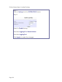
Table of Contents
OVERVIEW THE PRODUCT .............................................................. 1
Introduction ................................................................................................... 1
Features and Benefits................................................................................... 2
When to Use Which Mode........................................................................... 3
Access Point Client Mode ....................................................................... 3
Wireless Routing Client Mode.................................................................. 3
PERFORM BASIC CONFIGURATION .............................................. 5
Setup Management Port............................................................................. 5
To Setup DHCP Server............................................................................. 11
View Active DHCP Leases ..................................................................... 17
Reserve IP Addresses for Predetermined DHCP Clients .................... 18
Delete DHCP Server Reservation .......................................................... 20
Setup WLAN ................................................................................................. 21
Configure the Basic Setup of the Wireless Mode............................... 21
Scan for Site Survey................................................................................. 26
View Link Information ............................................................................. 29
Align the Antenna................................................................................... 31
Configure the Advanced Setup of the Wireless Mode .................... 33
View the Statistics.................................................................................... 35
Setup your WAN .......................................................................................... 36
Setup Telnet / SSH ....................................................................................... 44
Access the TELNET Command Line Interface..................................... 46
Access the Secure Shell Host Command Line Interface .................. 47
Set the WEB Mode ...................................................................................... 48
Setup SNMP.................................................................................................. 49
Setup SNMP Trap......................................................................................... 50
Use MAC Filtering ........................................................................................ 51
Add a MAC Address to the MAC Address List ................................... 52
Delete a MAC Address From All Access Points .................................. 55
Delete a MAC address from individual access point ....................... 57
Edit MAC Address from the MAC Address List.................................... 59
PERFORM ADVANCED CONFIGURATION.................................. 61
Setup Routing .............................................................................................. 61
Configure Static Routing........................................................................ 62
Use Routing Information Protocol............................................................. 63
Use Network Address Translation.............................................................. 64
Configure Virtual Servers Based on DMZ Host .................................... 65
Configure Virtual Servers Based on Port Forwarding ......................... 66
Configure Virtual Servers based on IP Forwarding ............................ 70
Control the Bandwidth Available ............................................................ 71
Enable Bandwidth Control .................................................................... 71
Configure WAN Bandwidth Control..................................................... 72
Configure LAN Bandwidth Control....................................................... 73
Perform Remote Management................................................................ 75
Setup Remote Management................................................................ 75
Setup Email Notification............................................................................. 76
Using Static Address Translation................................................................ 78
Dynamic DNS Setup ................................................................................... 79
To enable/disable Dynamic DNS Setup .............................................. 79
To manage Dynamic DNS List ............................................................... 80
USE THE WIRELESS EXTENDED FEATURES...................................... 84
Set Preferred APs......................................................................................... 84
Get Long Distance Parameters ............................................................ 85
Set Wireless Multimedia.............................................................................. 87
SECURE YOUR WIRELESS LAN....................................................... 90
Setup WEP .................................................................................................... 91
Setup WPA-Personal ................................................................................... 92
Setup 802.1x/RADIUS .................................................................................. 94
Setup WPA Enterprise ................................................................................. 96
CONFIGURE THE SECURITY FEATURES ......................................... 98
Use Packet Filtering..................................................................................... 98
Configure Packet Filtering ..................................................................... 98
Use URL Filtering......................................................................................... 101
Configure URL Filtering ......................................................................... 101
Configure the Firewall .............................................................................. 102
Configure SPI Firewall ........................................................................... 102
Use the Firewall Log .................................................................................. 106
View Firewall Logs ................................................................................. 106
ADMINISTER THE SYSTEM............................................................. 107
Use the System Tools................................................................................. 107
Use the Ping Utility ................................................................................. 107
Use Syslog ............................................................................................... 108
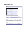
Set System Identity ................................................................................ 111
Setup System Clock .............................................................................. 112
Upgrade the Firmware with uConfig ................................................. 113
Upgrade the Firmware with Command Line Interface .................. 115
Perform Firmware Recovery ................................................................ 118
Backup or Reset the Settings............................................................... 120
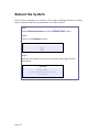
Reboot the System................................................................................ 123
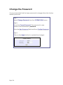
Change the Password.......................................................................... 124
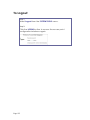
To Logout................................................................................................ 125
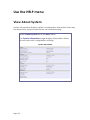
Use the HELP menu ................................................................................... 126
View About System............................................................................... 126
APPENDIX: USE THE COMMAND LINE INTERFACE ................... 127
Overview the Product
Introduction
The high-performance Wireless Network Access Point (AP) is designed
for enterprise and public access applications. Embedded with the
Atheros chipset, it boasts network robustness, stability and wider
network coverage. Based on 802.11, the access point supports highspeed data transmission of up to 54Mbps in the 2.4GHz frequency
band.
The access point is capable of operating in different modes, which
makes it suitable for a wide variety of wireless applications, including
long-distance deployments.
Designed with an external SMA connector offering excellent electrical
performance and compatible with SMA antennas, the access point
can be used for a wide variety of wireless applications and allows you
to position the wireless antenna in a better signal-broadcasting
location for improved wireless coverage and signal strength or simply in
a more convenient location.
Moreover, its integrated Power over Ethernet (PoE) allows the access
point to be used in areas where power outlets are not readily
available.
To protect your security and privacy, the access point is armed with
many enhanced wireless security features such as WPA, WPA2 (with
Advanced Encryption Standard encryption) MAC Address Filtering, IEEE
802.1x Authentication and 64/128-bit WEP (Wired Equivalent Privacy) to
ensure privacy for the heterogeneous mix of users within the same
wireless network.
The access point also incorporates a unique set of advanced features
such as: Virtual AP to deliver multiple services; Long-Range parameter
fine-tuning which provide the access point with the ability to autocalculate parameters such as slot time, ACK time-out and CTS time-out
to achieve a longer range; and Spanning Tree Protocol (STP) which
provides extra redundancy and the ability to auto-reconfigure when
there are changes in the network topology.
Page 1
Features and Benefits
Highly Secured Wireless Network
The access point supports the highest available wireless security
standard: WPA2. WPA2 has two different modes: WPA2-Personal for
SOHO users and WPA2-Enterprise for Enterprise users. The access point
also supports IEEE 802.1x for secure and centralized user-based
authentication. Wireless clients are thus required to authenticate
through highly secure methods like EAP-TLS, EAP-TTLS, and EAP-PEAP, in
order to obtain access to the network.
STP
Spanning-Tree Protocol provides path redundancy while preventing
undesirable loops in the network. It forces certain redundant data
paths into a standby (blocked) state. If one network segment in the
Spanning-Tree Protocol becomes unreachable, or if Spanning-Tree
Protocol costs change, the spanning-tree algorithm reconfigures the
spanning-tree topology and re-establishes the link by activating the
standby path.
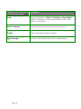
HTTPS
The access point supports HTTPS (SSL) in addition to the standard HTTP.
HTTPS (SSL) features additional authentication and encryption for
secure communication.
Telnet
Telnet allows a computer to remotely connect to the access point CLI
(Command Line Interface) for control and monitoring.
SSH
SSH (Secure Shell Host) establishes a secure host connection to the
access point CLI for control and monitoring.
WDS2
WDS2 (Wireless Distributed System 2) links up access points to create a
wider network in which mobile users can roam while still staying
connected to available network resources.
Page 2
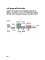
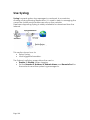
When to Use Which Mode
Access Point Client Mode
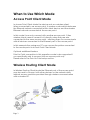
In Access Point Client Mode the device acts as a wireless client.
When connected to an access point, it creates a network link between
the Ethernet network connected at this client device, and the wireless
Ethernet network connected at the access point.
In this mode it can only connect with another access point. Other
wireless clients cannot connect to it directly unless they are also
connected to the same access point – allowing them to communicate
with all devices connected to the Ethernet port of the access point.
In this example the workgroup PCs can access the printer connected
to the access point in Access Point Client Mode.
Optional additional feature:
Point-to-Point connection in this operation mode is also supported if
you specifically wish to connect with an access point only.
Please refer to the Point-to-Point setup section.
Wireless Routing Client Mode
In Wireless Routing Client Mode the Ethernet port of the access point
may be used to connect with other devices on the network while
Internet access would be provided through wireless communication
with a wireless ISP.
Page 3
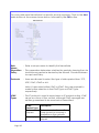
Broadband Internet Access Type:
Static IP Address
Use Static IP Address if you have subscribed to a fixed IP address or to a
range of fixed IP addresses from your ISP.
Dynamic IP Address
With Dynamic IP Address the access point requests for, and is
automatically assigned an IP address by your ISP, for instance:
• Singapore Cable Vision
• @HOME Cable Services
PPP over Ethernet (PPPoE)
Use PPPoE if you are using ADSL services in a country utilizing standard
PPPoE authentication, for instance:
• Germany with T-1 Connection
• Singapore with SingNet Broadband or Pacific Internet
Broadband
PPTP
Use PPTP if you are using ADSL services in a country utilizing PPTP
connection and authentication.
Layer Two Tunneling Protocol (L2TP)
L2TP enables ISPs to operate Virtual Private Networks (VPNs)
Page 4
Perform Basic Configuration
Setup Management Port
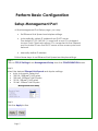
At the Management Port Setup page, you may:
•
Set Ethernet Link Speed and duplex settings.
•
Automatically obtain IP address from DHCP server.
The default IP 192.168.168.1 is used until a new IP is obtained.
Access Point Clients also allows PCs connected to the Ethernet
port to obtain IP from the DHCP server at the access point end
network.
•
Manually define IP address
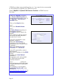
Follow these steps to set Ethernet Link Speed and duplex settings.
Step 1:
Click on TCP/IP Settings from Management Setup from the CONFIGURATION menu.
Step 2:
Select the desired Ethernet Link Speed and duplex settings.
• Auto: Automatic Detection
• 100 Full: 100BaseT Full-Duplex
• 100 Half: 100BaseT Half-Duplex
• 10 Full: 10BaseT Full-Duplex
• 10 Half: 10BaseT Half-Duplex
Step 2:
Click the Apply button.
Page 5
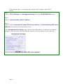
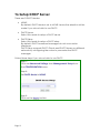
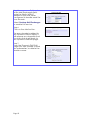
Follow these steps to automatically obtain the IP address from DHCP
server.
Step 1:
Click on TCP/IP Settings from Management Setup from the CONFIGURATION menu.
Step 2:
Select to Automatically obtain IP address.
Step 3:
Select to either Automatically obtain DNS server address or Use the following DNS server
addresses and enter the parameters, if any.
In the Management Port Setup page, refer to the table below to replace the default
settings of Access point with appropriate values to suit the needs of your network.
If you choose to Automatically obtain DNS server address.
Page 6
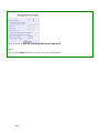
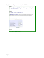
If you choose to Use the following DNS server addresses.
Step 3:
Click on the Apply button to save your new parameters.
Page 7
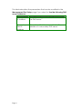
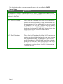
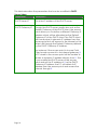
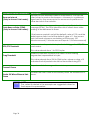
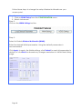
This table describes the parameters that can be modified in the
Management Port Setup page if you select to Use the following DNS
server addresses.
Parameters
Description
Primary DNS
Your ISP usually provides the IP address of
IP Address
the DNS server.
Secondary
DNS IP
Address
Page 8
This optional field is reserved for the IP
address of a secondary DNS server.
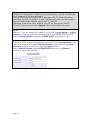
Follow these steps to manually define the IP address.
Step 1:
Click on TCP/IP Settings from Management Setup from the
CONFIGURATION menu.
Step 2:
Select to Use the following IP address.
In the Management Port Setup page, refer to the table below to
replace the default settings of Access point with appropriate
values to suit the needs of your network.
The parameters are the same in routing mode.
Step 3:
Click on the Apply button to save your new parameters.
Page 9
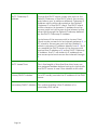
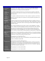
This table describes the parameters that can be modified in the
Management Port Setup page.
Parameters
Description
IP Address
When the DHCP server of the access point is enabled (unless
you set a different DHCP Gateway IP Address), this LAN IP
Address would be allocated as the Default Gateway of the
DHCP client.
The IP address of your Access point is set by default to
192.168.168.1.
Network
Mask
The Network Mask serves to identify the subnet in which your
Access point resides. The default network mask is
255.255.255.0.
Default
Gateway IP
(Optional) As a bridge Access Point, the access point does
not usually communicate with devices on other IP subnets.
However, the Default Gateway a PC allows the access point
to communicate with devices on different subnets. For
instance, if you want to access the access point from the
Internet or from a router on the LAN, enter the router IP
address in the Default Gateway IP field.
The Default Gateway IP address of your access point is set to
nil by default.
Primary DNS
IP Address
Your ISP usually provides the IP address of the DNS server.
Secondary
DNS IP
Address
This optional field is reserved for the IP address of a
secondary DNS server.
Page 10
To Setup DHCP Server
There are 3 DHCP Modes:
•
NONE
By default, DHCP Mode is set to NONE. Leave the selection at this
mode if you do not wish to use DHCP.
•
DHCP Server
Select this mode to setup a DHCP server.
•
DHCP Relay
Select this mode to setup a DHCP relay.
By default, DHCP broadcast messages do not cross router
interfaces.
DHCP Relay supports DHCP Clients and DHCP Servers on different
networks by configuring the router to pass selective DHCP
messages.
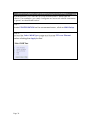
Follow these steps if you do not wish to use DHCP.
Step 1:
Click on Advanced Settings from Management Setup from
the CONFIGURATION menu.
Step 2:
Set DHCP Mode to NONE.
Step 3:
Click on the Apply button.
Page 11
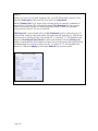
The following will guide you to setup the DHCP Server.
Step 1:
Click on Advanced Settings from Management Setup from
the CONFIGURATION menu.
Step 2:
Set DHCP Mode to DHCP Server.
In DHCP Server Setup, refer to the table below to set the
appropriate values to suit the needs of your network.
Step 3:
Click on the Apply button.
Page 12
This table describes the parameters that can be modified in DHCP
Server Setup.
Parameters
Description
The fields DHCP Start IP Address and DHCP End IP Address fields allow you to
define the range of IP addresses from which the DHCP Server can assign an IP
address to the LAN.
DHCP Start IP Address
This is the first IP address that the DHCP server will
assign and should belong to the same subnet as
the access point. For example if the access point
IP address is 192.168.168.1 and the network mask is
192.168.168.1 and 255.255.255.0, the DHCP Start IP
Address should be 192.168.168.X, where X can be
any number from 2 to 254. It is pre-set to
192.168.168.100.
DHCP End IP Address
This is the last IP address that the DHCP server can
assign and should also belong to the same subnet
as your access point. For example if the access
point IP address is 192.168.168.1 and the network
mask is 192.168.168.1 and 255.255.255.0, the DHCP
End IP Address should be 192.168.168.X, where X
can be any number from 2 to 254. It is pre-set as
192.168.168.254.
Page 13
DHCP Gateway IP
Address
Though the DHCP server usually also acts as the
Default Gateway of the DHCP client, the access
point allows you to define a different Gateway IP
Address which will be allocated as the Default
Gateway IP of the DHCP client. The DHCP client
will thus receive its dynamic IP address from the
access point but will access to the Internet or the
other LAN through the Default Gateway defined
by the DHCP Gateway IP Address.
For instance if the access point in Access Point
Client mode connects to an Internet gateway X, a
PC wired to the access point will be unable to
obtain a dynamic IP address directly from X. But if
you enable the DHCP server of the access point
and set the IP address of X as the DHCP Gateway
IP Address, the PC will obtain its IP address from
the access point and access the Internet through
X.
DHCP Lease Time
This is the length of time that the client may use
the assigned address before having to check with
the DHCP server to see if the Address is still valid.
Primary DNS IP Address
Your ISP usually provides the IP address of the DNS
server.
Secondary DNS IP Address This optional setting is the IP address of a
secondary DNS server.
Page 14
The following will guide you to setup the DHCP Relay.
Step 1:
Click on Advanced Settings from Management Setup from
the CONFIGURATION menu.
Step 2:
Set DHCP Mode to DHCP Relay.
In DHCP Server Setup, refer to the table below to set the
appropriate values to suit the needs of your network.
Step 3:
Click on the Apply button.
Page 15
This table describes the parameters that can be modified in DHCP
Server Setup.
Parameters
Description
DHCP Server IP
This is the IP address of the DHCP server.
DHCP Gateway IP
Though the DHCP server usually also acts as the
Default Gateway of the DHCP client, the access
point allows you to define a different Gateway IP
Address which will be allocated as the Default
Gateway IP of the DHCP client. The DHCP client
will thus receive its dynamic IP address from the
access point but will access to the Internet or the
other LAN through the Default Gateway defined
by the DHCP Gateway IP Address.
For instance if the access point in Access Point
Client mode connects to an Internet gateway X,
a PC wired to the access point will be unable to
obtain a dynamic IP address directly from X. But
if you enable the DHCP server of the access
point and set the IP address of X as the DHCP
Gateway IP Address, the PC will obtain its IP
address from the access point and access the
Internet through X.
Page 16
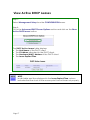
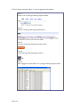
View Active DHCP Leases
Step 1:
Select Management Setup from the CONFIGURATION menu.
Step 2:
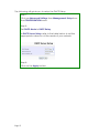
Go to the Advanced DHCP Server Options section and click on the Show
Active DHCP leases button.
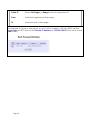
The DHCP Active Leases table displays:
• The Host Name of the DHCP client.
• The IP Address allocated to the DHCP client.
• The Hardware (MAC) Address of the DHCP client.
• The Lease Expired Time.
NOTE
Invalid date and time displayed in the Lease Expired Time column
indicates that the clock of the access point has not been set properly.
Page 17
Reserve IP Addresses for Predetermined
DHCP Clients
A reserved IP address is excluded from the pool of free IP addresses the
DHCP server draws on for dynamic IP address allocation.
For instance if you set up a publicly accessible FTP or HTTP server within
your private LAN, while that server requires a fixed IP address you would
still want the DHCP server to dynamically allocate IP addresses to the
rest of the PCs on the LAN.
Step 1:
From the Advanced DHCP Server Options section click on the DHCP Server
Reservations button.
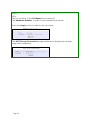
Step 2:
Click on the Add button.
Page 18
Step 3:
Fill in:
The host portion of the IP Address to be reserved.
The Hardware Address, in pairs of two hexadecimal values.
Press the Apply button to effect your new entry.
The DHCP Server Reservations page refreshes to display the currently
reserved IP addresses.
Page 19
Delete DHCP Server Reservation
Step 1:
Select the reserved IP address to delete.
Step 2:
Click on the Delete button.
The DHCP Server Reservations table refreshes to display your changes.
Page 20
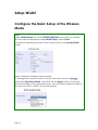
Setup WLAN
Configure the Basic Setup of the Wireless
Mode
Step 1:
Select WLAN Setup from the CONFIGURATION menu and you will see
the sub menus expanded under WLAN Setup, select Basic.
The default operating mode of the access point is the Access Point
mode.
Step 2: (Optional: Change Current mode)
To change the current mode of the access point click on Change,
select the Operation Mode, and click on the Apply button to access
the setup page of the selected mode. You will be prompted to reboot
the access point to effect the mode setting.
Page 21
Step 3:
Enter the parameters in their respective fields, click on the
Apply button and reboot your device to let your changes
take effect.
Note that the WLAN Basic Setup pages for the modes are
different.
Example: WLAN Basic Setup page for Client Mode
Example: WLAN Basic Setup page for Access Point
Page 22
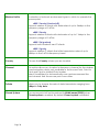
WLAN Basic Setup
page Parameters
Description
The Current Mode
The default operating mode is the Access Point mode. Operating
modes:
•
•
•
•
•
•
•
Access Point Mode
Client Mode
Wireless Routing Client
Gateway Mode
Wireless Adapter Mode
Transparent Client Mode
Repeater Mode
You can toggle the modes by clicking on the Change button.
ESSID
Enter a preferred name for the wireless network. Your wireless
clients must be configured with the same ESSID.
This case-sensitive entry can consist of a maximum of 32
characters.
Site Survey
A list of wireless devices in the WLAN that are detected by your
access point. Information such as MAC address, channel, SSID,
algorithm and signal strength can be found in the listing.
This feature is supported by the Access Point Client and Wireless
Routing Client modes.
Page 23
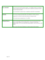
Wireless Profile
A selection of network environment types in which to operate the
access point:
• 802.11a only (Version AG)
Supports wireless A clients with data rates of up to 54Mbps in the
frequency range of 5.4GHz.
• 802.11b only
Supports wireless B clients with data rates of up to 11Mbps in the
frequency range of 2.4GHz.
• 802.11b/g mixed
Supports both wireless B and G clients.
• 802.11g only
Supports wireless-G clients that offer transmission rates of up to
54Mbps in the 2.4GHz frequency band.
Country
Choose the Country where you are located.
Channel
This option allows you to select a frequency channel for the wireless
communication and is only available in the Access Point, Point to
Point and Point to Multiple Point modes.
Select SmartSelect to automatically scan and recommend the
best channel that the access point can utilize.
Tx Rate
Allows you to choose the rate of data transmission ranging from
1Mbps to Fully Auto.
Closed System
The access point will not broadcast its WLAN name (ESSID) when
Closed system is enabled. By default Closed system is disabled.
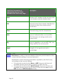
Page 24
Act as RootAP
The access point will connect with 1, or multiple clients to create a
point-to-point and point-to-multi-point connection network with 2
or more access points.
This connection mode is fully compliant with 802.1h standards.
VLAN ID
This is the number that identifies the different virtual network
segments to which the network devices are grouped.
This can be any number from 1 to 4094.
Channel Survey
A list of channels that are detected by your access point in the
WLAN. Information such as frequency, channel, MyQuality,
NeighQuality, APCount and Recommendation can be found in the
listing.
The Access Point and Gateway modes support this feature.
Page 25
Scan for Site Survey
(Available in Client and Wireless Routing Client modes)
Step 1:
In the Mode Setup page click on the Site Survey button.
The Site Survey provides a list of the MAC addresses (BSSID) and SSID of
neighbouring access points detected, the Chan (channels), Auth
(Authentication), Alg (Algorithm) used, and the strength of the Signal
received.
Page 26
Step 2:
To connect the client to one of the access points detected, select the
radio button corresponding to the access point you want to connect
to.
Step 3:
Click on the Apply button to effect the change and return to the setup
page.
Step 4:
Click on the Refresh button to update the screen.
Page 27
Read-Only Parameters of
Neighbouring Access Points
Viewable from Site Survey page
Description
Bssid
Wireless MAC address of the access point
in an wireless network infrastructure.
SSID
Network name that uniquely identifies the
network to which the access point is
connected.
Chan
Channel being used for transmission.
Auth
Types of authentication, such as WPA,
WPA-Personal, etc being used by the
access point.
Alg
Types of algorithm, such as WEP, TKIP, etc
being used by the access point.
Signal
Strength of the signal received in
percentage.
NOTE
Site Survey is used to scan and display all access points based on the
current security setting of your access point.
Explanation of the following information supplied by the Site Survey
according to the security setting:
• If the security mode is set to None or WEP, the scan will show all
available access points with no security or WEP security
• If the security mode is set to WPA-Personal, the scan will show all
available access points with all types of security from no security,
WEP security to WPA-Personal security.
Page 28
View Link Information
(Available in Client and Wireless Routing Client modes)
To view the connection status when the client is linked to another
access point, click on the Show Link Information button.
The Link Information table displays the following data:
Page 29
Parameters Viewable from
Link Information page
Description
State
Displays whether the State is Scanning or Associated,
and MAC address of the access point to which the
client is connected.
Current Channel
Channel presently being used for transmission.
Tx Rate
Rate of data transmission in Mbps.
Signal Strength
Intensity of the signal received, in percentage.
Page 30
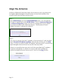
Align the Antenna
Antenna Alignment precisely aligns the antenna over long distances
for higher signal strength to improve the connection between the
access point and another access point.
Step 1:
Select WLAN Setup from the CONFIGURATION menu. You will see the
sub-menus expanded under WLAN Setup. Click on Antenna Alignment.
The Antenna Alignment page can act as a diagnostic tool to check
the communication with a remote device. The remote AP MAC
Address is preset to all zeros by default.
Step 2:
If you wish to specify the MAC address of the remote AP, edit the field
next to Remote AP Address (option), followed by clicking on the Start
button. A pop-up status screen will display, allowing you to monitor the
signal strength received from the remote access points.
If there is no specified access point with the specified MAC address,
this screen will display. To abort or to key in the MAC address of
another available remote access point, click on the Stop button.
Page 31
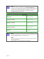
NOTE
If no MAC address is entered, the Antenna Alignment tool
will make use of the SSID to align the antenna. Please ensure
that the correct SSID is entered. If more than one access
point share the same SSID, the access point with the
strongest signal will be shown.
Signal Strength
(RSSI Value) Indicated by DIAG LED
Status of DIAG LED
Above 20
Stays turned on.
Between 19 and 17
Flashes 6 times.
Between 17 and 14
Flashes 3 times.
Between 13 and 10
Flashes once.
Below 10
Turns off.
NOTE
Outdoor long distance connection should preferably have a
signal strength of a RSSI of 10 and above.
NOTE
To ensure proper functionality of the device, select to Stop
antenna alignment.
Alternatively, you may also reboot the device.
Page 32
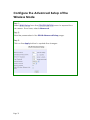
Configure the Advanced Setup of the
Wireless Mode
Step 1:
Select WLAN Setup from the CONFIGURATION menu to expand four
sub-menus. From here, select Advanced.
Step 2:
Enter the parameters in the WLAN Advanced Setup page.
Step 3:
Click on the Apply button to update the changes.
Page 33
Advanced Setup Parameters
Beacon Interval
(Only in Access Point mode)
Data Beacon Rate (DTIM)
(Only in Access Point mode)
Description
Amount of time between beacon transmissions. This tells the
client when to receive the beacon. A beacon is a guidance
signal sent by the access point to announce its presence to
other devices in the network.
How often the beacon contains a delivery traffic indication
message (DTIM). The DTIM identifies which clients have data
waiting to be delivered to them.
If the beacon period is set at the default value of 100, and the
data beacon rate is set at the default value of 1, the access
point will send a beacon containing a DTIM every 100
kilomicrosecond (1 kilomicrosecond equals 1,024 microsecond)
RTS/CTS Threshold
Minimum size of a packet in bytes that will trigger the RTS/CTS
mechanism.
Frag Threshold
This value extends from 1 to 2312 bytes.
Maximum size that a packet can reach without being
fragmented, represented in bytes.
This value extends from 256 to 2346 bytes, where a value of 0
indicates that all packets should be transmitted using RTS.
Drop-down list of a range of transmission power.
Transmit Power
Radio Off When Ethernet Link
Down
Disables the radio card automatically when the Ethernet link is
down.
NOTE
The values illustrated in the example are suggested values for
their respective parameters.
Page 34
View the Statistics
The Statistics feature reveals information on the wireless device
connected to the WLAN.
Step 1:
Select WLAN Setup from the CONFIGURATION menu. The sub-menus
under WLAN Setup expand, select Statistics.
Wireless clients that are connected to the WLAN are shown in the
WLAN Station List.
Step 2:
Click on the Refresh button to get the latest information on the
availability of wireless clients in the wireless network.
Step 3:
To check the details on an individual wireless client, click on the
corresponding MAC Address in the WLAN Station List.
The statistics of the selected wireless client displays.
In Client mode you are not allowed to view the information of other
wireless clients, to do that you need to change to the Access Point
mode.
Page 35
Setup your WAN
(Available in Wireless Routing Client and Gateway modes)
NOTE:
Any changes to the WAN Setup will only take effect after rebooting.
Setup your WAN to share Internet connection among the clients of the
access point.
Setup your WAN for cable internet whereby WAN IP address is
dynamically assigned by ISP
The access point is pre-configured to support this WAN type.
However, you may verify the WAN settings with the following
steps:
Step 1:
Under CONFIGURATION on the command menu, select WAN Setup.
S t ep 2 :
On the WAN Dynamic Setup screen, verify that the WAN Type is
Dynamic (DHCP). Otherwise, click on the Change button.
Step 3:
Select Dynamic IP Address and hit the Apply button.
Reboot to let the settings take effect.
Page 36
Note:
Additional configuration might be required before your ISP will allocate
an IP address to the access point.
Certain ISPs require authentication through a DHCP Client ID before
releasing a public IP address to you. The access point uses the System
Name in the System Identity as the DHCP Client ID.
Therefore if this is the case, refer to your ISP for the correct DHCP
Client ID to be set and follow steps 4 - 5 to accomplish the setup.
Step 4:
Steps 4 - 5 are for those who need to set up the System Name in System
Identity so that your ISP can authenticate it as a valid DHCP Client ID.
Select System Identity under the SYSTEM TOOLS command menu.
Step 5:
Enter the DHCP Client ID assigned by your ISP for the System Name. You
may also enter in a preferred System Contact person and the System
Location of the access point. Click the Apply button.
Select Reboot System under SYSTEM TOOLS and click the Reboot
button to effect the settings.
Page 37
Setup your WAN for cable internet whereby fixed WAN IP
address is assigned by ISP
WAN Setup Parameters Example:
• IP Address: 203.120.12.240
• Network Mask: 255.255.255.0
• Gateway IP Address: 203.120.12.2
Step 1:
Under CONFIGURATION on the command menu, select WAN Setup.
Step 2:
Access the Select WAN Type page and select Static IP Address before
clicking the Apply button.
Step 3:
Fill in the information provided by your ISP in the IP Address, Network
Mask and Gateway IP Address fields, and click the Apply button.
Select Reboot System under SYSTEM TOOLS and click the Reboot button
to effect the settings.
Page 38
Setup your WAN for ADSL Internet using PPP over Ethernet
If you subscribe to an ADSL service using PPP over Ethernet (PPPoE)
authentication, you can set up your access point’s WAN type as
follows. For example, you may configure an account whose username
is ‘guest’ as described below:
Step 1:
Under CONFIGURATION on the command menu, click on WAN Setup..
Step 2:
Access the Select WAN Type page and choose PPP over Ethernet
before clicking the Apply button.
Page 39
Step 3:
Enter your account name assigned by your ISP (Example: guest) in the
field for Username, followed by your account Password.
Select Always-On if you want your access point to always maintain a
connection with the ISP. Otherwise select On-Demand for the access
point to connect to the ISP automatically when it receives Internet
requests from the PCs in your network.
Idle Timeout is associated with the On-Demand option, allowing you to
specify the value in seconds after the last Internet activity by which the
access point will disconnect from the ISP. A value of “0” will disable idle
timeout. Reconnect Time Factor is also associated with the Always-on
option and specifies the maximum time the access point will wait before
reattempting to connect with your ISP. A value of “0” will disable idle
timeout. Click the Apply button and Reboot the access point.
Page 40
You can limit the maximum size a packet can be in a network by setting
the MTU (Maximum Transmissible Unit).
Click the MTU Button in Advanced WAN Options.
The MTU Value has a range of 1 to 1492.
Enter the MTU Value and click Apply.
Page 41
Setup your WAN for ADSL Internet using Point-to-Point Tunneling
Protocol (PPTP)
WAN Setup Parameters Example:
• IP Address: 203.120.12.47
• Network Mask: 255.255.255.0
• VPN Server: 203.120.12.15
Step 1:
Under CONFIGURATION on the command menu, click on WAN Setup..
Step 2:
Access the Select WAN Type page and select PPTP before clicking the
Apply button.
Page 42
Step 3:
Fill in the information provided by your ISP in the IP Address, Network
Mask, VPN Server, and DHCP fields, and click the Apply button.
Select Reboot System under SYSTEM TOOLS and click the Reboot button
to effect the settings
The Idle Timeout setting allows you to specify the value in seconds after
the last Internet activity by which the access point will disconnect from
the ISP. A value of “0” will disable idle timeout.
Page 43
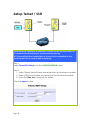
Setup Telnet / SSH
Telnet allows a computer to remotely connect to the access point CLI
(Command Line Interface) for control and monitoring.
SSH (Secure Shell Host) establishes a secure host connection to the
access point CLI for control and monitoring.
Step 1:
Select Telnet/SSH Setup from the CONFIGURATION menu.
Step 2:
1. Select Telnet Server Enable and enter the Port Number to enable.
2. Select SSH Server Enable and enter the Port Number to enable.
3. Enter the Time out in seconds for Telnet.
Click the Apply button.
Page 44
Step 3:
To add user:
1. Click the Add button.
2. In Add User Entry Page, enter the User Name, Password, and
specify whether the user is granted permission to Read Only or
Read/Write.
3. Click the Apply button.
To Delete User:
1. Select which user to Delete.
2. Click the Delete button.
To Refresh User Management list click the Refresh button.
Page 45
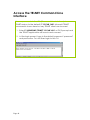
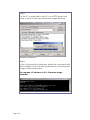
Access the TELNET Command Line
Interface
You may connect to the CLI (Command Line Interface) via a
TELNET session to the default IP 192.168.168.1 Microsoft TELNET
command is shown here but any TELNET client can be used.
1. Enter C:\WINDOWS\TELNET 192.168.168.1 at DOS prompt and
the TELNET application will launch and connect.
2. At the login prompt, type in the default password “password”
and press enter. You will then login to the CLI.
Page 46
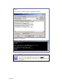
Access the Secure Shell Host Command
Line Interface
SSH provides the best remote access security using different forms of
encryption and ciphers to encrypt sessions, and providing better
authentication facilities and features that increase the security of other
protocols.
An encrypted connection like SSH is not viewable on the network. The server
can still read the information, but only after negotiating the encrypted session
with the client.
SSH CLI has a command line interface.
Page 47
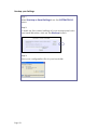
Set the WEB Mode
The access point supports HTTPS (SSL) featuring additional
authentication and encryption for secure communication, in addition to
the standard HTTP.
Step 1:
Select Web Management Setup from the CONFIGURATION menu.
Step 2:
1. Select whether to set web server to HTTP or HTTPS (SSL) mode.
2. Click Apply.
Changes will be effected after reboot.
Page 48
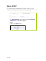
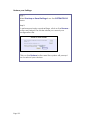
Setup SNMP
The Simple Network Management Protocol (SNMP) is a set of
communication protocols that separates the management software
architecture from the hardware device architecture.
Step 1:
Select SNMP Setup from the CONFIGURATION menu.
Step 2:
Select Enable from the SNMP State drop-down list.
The Read Password is set to public while the Read/Write
Password is set to private by default.
Step 3:
Click on the Apply button.
Page 49
Setup SNMP Trap
The SNMP Trap saves network resources through eliminating the need
for unnecessary SNMP requests by providing notification of significant
network events with unsolicited SNMP messages.
Step 1:
Select SNMP Setup from the CONFIGURATION menu.
Step 2:
1. Select whether to Enable or Disable the
SNMP Trap.
2. Enter the Remote IP Address or DNS.
3. Enter the Remote Port.
This is the port number of the SNMP manager.
4. Enter the Community.
This is used to authenticate message, and is
included in every packet that is transmitted
between the SNMP manager and agent.
5. Click on the Apply button.
Page 50
Use MAC Filtering
MAC Filtering acts as a security measure by restricting user network
access according to MAC address. Each WLAN or radio card supports
up to 16 virtual access points and has its own MAC address listing.
NOTE
MAC Filtering will not filter any MAC address from the Ethernet
port.
Page 51
Add a MAC Address to the MAC Address
List
Step 1:
Select MAC Filtering from WLAN Setup.
The MAC Address Filtering page displays.
In this page you may also set the MAC Filtering Status to Enable or
Disable for access points and set the Policy to either Accept or Deny
MAC addresses.
MAC Filtering set to Enable with Policy to Accept only
the MAC addresses in the MAC Filter Address List and
deny all other MAC addresses.
MAC Filtering set to Enable with Policy to Deny all the
MAC addresses in the MAC Filter Address List and
accept all other MAC addresses.
MAC Filtering set to Disable. Whether Policy is set to
Enable or Deny does not matter.
MAC Filtering set to Disable. Whether Policy is set to
Enable or Deny does not matter.
Click the Edit button.
Page 52
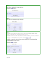
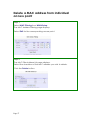
Step 2:
MAC Filter Address List page displays.
Click the Add button.
Step 3:
The Add MAC Address page displays.
Step 4:
Enter the MAC Address of the client in the format xx-xx-xx-xx-xx-xx,
where x can take any value from 0 to 9 or a to f.
Enter the Comment. This describes the MAC Address you have entered.
To apply to all virtual access points, check Apply to All.
To apply to specific virtual access point, select the checkbox of the
corresponding access point.
Click the Apply button.
Page 53
Step 5:
MAC Filter Address List page displays with updated MAC Address List.
NOTE
Please reboot to effect all changes and new MAC address entries.
Page 54
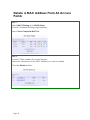
Delete a MAC Address From All Access
Points
Step 1:
Select MAC Filtering from WLAN Setup.
The MAC Address Filtering page displays.
Select View Complete MAC List.
S t ep 2 :
The MAC Filter Address List page displays.
Select the checkbox of the MAC address you wish to delete.
Click the Delete button.
Page 55
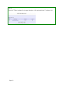
Step 3:
The MAC Filter Address List page displays with updated MAC Address List.
Page 56
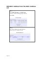
Delete a MAC address from individual
access point
S t ep 1 :
Select MAC Filtering from WLAN Setup.
The MAC Address Filtering page displays.
Select Edit for the corresponding access point.
S t ep 2 :
The MAC Filter Address List page displays.
Select the checkbox of the MAC address you wish to delete.
Click the Delete button.
Page 57
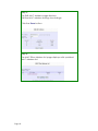
S t ep 3 :
The MAC Filter Address List page displays with updated MAC Address
List.
Page 58
Edit MAC Address from the MAC Address
List
Step 1:
Select MAC Filtering from WLAN Setup.
The MAC Address Filtering page displays.
Select Edit.
Step 2:
MAC Filter Address List page displays.
Select the MAC address to edit.
Page 59
Step 3:
The Edit MAC Address page displays.
Edit the MAC address settings accordingly.
Click the Save button.
Step 4:
The MAC Filter Address List page displays with updated
MAC Address List.
Page 60
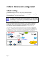
Perform Advanced Configuration
Setup Routing
(Available in Wireless Routing Client and Gateway modes)
The access point allows you to add a static routing entry into its routing
table to re-route IP packets to another access point. This is useful if your
network has more than one access point.
Important:
You do NOT need to set any routing information if you are simply
configuring the access point for broadband Internet sharing. The
wrong routing configuration might cause the access point to
function improperly.
In this network, the main office of subnet 192.168.168.0 contains two
routers: the office is connected to the Internet via the access point
(192.168.168.1) and to the remote office via 192.168.168.254 The
remote office resides on subnet 192.168.100.0
You can add a static routing entry into the access point routing table
so that IP packets from the clients in the main office with a destination
IP address of 192.168.100.X where X is any number from 2 to 254 will be
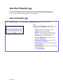
re-routed to the router, which acts as the gateway to that subnet.
Page 61
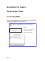
Configure Static Routing
Step 1:
Select Routing from the
CONFIGURATION command
menu. The System Routing Table
page displays. Initially the table
contains the default routing
entries of the access point.
Step 2:
Click on the Static Routing Table
button, then click the Add
button.
Step 3:
Enter the Destination IP Address,
Destination Net Mask, and
Gateway IP Address, and click
the Add button.
The Static Routing Table reflects
the entry.
Page 62
Use Routing Information Protocol
(Available in Wireless Routing Client and Gateway modes)
RIP (Routing Information Protocol) allows information to be exchanged
within a set of routers under the same administration.
RIPv1 bases the path used to pass traffic between routers on the fewest
number of hops between the source and destination IP addresses
within a packet. Routers broadcast RIPv1 information on all router
interfaces every 30 seconds and process the information from other
routers to determine if a better path is available. RIPv2 is more secure,
and performs broadcasting and the assignment of IP address more
efficiently.
Step 1:
Under the CONFIGURATION command
menu, click on Routing to be brought
to Route Information Protocol.
Step 2:
Select to Enable RIP Status.
Select either RIPv1 or RIPv2.
On this page, click the Apply button.
Page 63
Use Network Address Translation
(Available in Wireless Routing Client and Gateway modes)
NAT (Network Address Translation) allows multiple PCs in a private
network to share a single public IP address by using different TCP ports
to identify requests coming from different PCs, and is enabled by
default. Computers in the private LAN behind the access point will not
be directly accessible from the Internet. However, employing virtual
servers allows the hosting of Internet servers by using IP/ Port Forwarding
and De-Militarized Zone hosting.
Step 1:
Select NAT from the
CONFIGURATION command
menu. To disable it, select the
Disable radio button.]
Step 2:
Click the Apply button to
effect the setting.
Important:
NAT provides for effective broadband Internet sharing, do
NOT disable NAT unless it is absolutely necessary.
Page 64
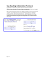
Configure Virtual Servers Based on DMZ
Host
DMZ (De-Militarized Zone) makes specific PCs in a NAT-enabled
network directly accessible from the Internet.
With NAT, the access point keeps track of which client is using which
port number and forwards Internet replies to the client according to
the port number in the reply packet. Reply packets with unrecognized
port numbers are discarded, but with DMZ, these packets are
forwarded to the DMZ-enabled PC instead.
Step 1:
Select NAT from the CONFIGURATION
command menu.
Step 2:
Click on the DMZ button in Advanced
NAT Options.
Step 3:
Enter the Private IP Address of the DMZ
host on the NAT DMZ IP Address page.
To disable DMZ, enter 0.0.0.0
Click the Apply button.
NOTE
1. DMZ may not function properly if the DMZ host IP address
is changed due to DHCP, therefore, Static IP Address
configuration is recommended for the DMZ host.
2. Please note that the DMZ host is susceptible to malicious
attacks as ALL of its ports are exposed to the Internet.
Page 65
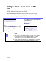
Configure Virtual Servers Based on Port
Forwarding
Virtual Server based on Port Forwarding forwards Internet requests arriving at
the access point WAN interface to specific PCs in the private network based
on their ports.
Step 1:
Select NAT from the CONFIGURATION command menu.
Step 2:
Click the Port Forwarding button in Advanced NAT Options.
Step 2:
Click the Add button on the Port Forward Entries page.
Page 66
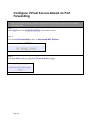
Step 3:
In the Add Port Forward Entry page, you can set up a Virtual Server for a Known
Server type by selecting from a drop-down menu or you can define a Custom Server.
Page 67
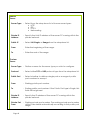
Known
Server
Server Type : Select from the drop-down list of known server types:
• HTTP
• FTP
• POP3
• Netmeeting
Private IP
Address
: Specify the LAN IP address of the server PC running within the
private network.
Public IP
: Select All, Single, or Range from the dropdown list.
From
To
:
Enter the beginning of the range.
: Enter the end of the range.
Custom
Server
Server Type : Define a name for the server type you wish to configure.
Protocol
: Select either TCP or UDP protocol type from the dropdown list.
Public Port
: Select whether to define a single port or a range of public
port numbers to accept.
From
: Starting public port number
To
: Ending public port number. If the Public Port type is Single, this
field will be ignored.
Private IP
Address
: Specify the IP address of the server PC running within the
private network.
Private Port
From
: Starting private port number. The ending private port number
will be calculated automatically according to the public port
range.
Page 68
Public IP
: Select All, Single, or Range from the dropdown list.
From
: Enter the beginning of the range.
To
: Enter the end of the range.
For example to set up a web server on a PC with IP address 192.168.168.55, set the
Server Type as HTTP and set the Private IP Address as 192.168.168.55, then click on the
Add button.
Page 69
Configure Virtual Servers based on IP
Forwarding
If you are subscribed to more than one IP address from your ISP, virtual
servers based on IP forwarding can forward all Internet requests
regardless of the port number to defined computers in the private
network.
Step 1:
Select NAT from the
CONFIGURATION command
menu.
Step 2:
Click the IP Forwarding button in
Advanced NAT Options.
Step 3:
In the Add IP Forward Entry page,
enter the Private IP Address and
Public IP Address.
In this example, we would like all
requests for 213.18.213.101 to be
forwarded to a PC with Private IP
Address 192.168.168.55.
NOTE
Please ensure that
you are subscribed to
the Public IP Address
you intend to forward
from.
Step 4:
Click the Add button.
Step 5:
The IP Forward Entries page
reflects your new addition.
Page 70
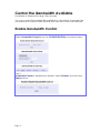
Control the Bandwidth Available
(Available in Wireless Routing Client mode)
You can control the bandwidth available to subscribers to prevent the
occurrence of massive data transfer that can slow down the network.
Enable Bandwidth Control
Step 1:
Select Bandwidth Control from the CONFIGURATION command menu.
Step 2:
Bandwidth Control is disabled by default, select Enable, and click the
Apply button.
Page 71
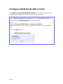
Configure WAN Bandwidth Control
The Upload / Download Bandwidth Setting can limit throughput to the
defined rates regardless of the number of connections.
Step 1:
Select WAN Bandwidth Control Setup from the Bandwidth Control submenu from the CONFIGURATION command menu.
Step 2:
Enter the Download Total Rate and Upload Total Rate.
The default values are 0, which indicates that there is no bandwidth
limit.
Click the Apply button.
Page 72
Configure LAN Bandwidth Control
Bandwidth Control can also limit LAN users’ throughput.
Step 1:
Select LAN Bandwidth Control Setup from the Bandwidth Control submenu from the CONFIGURATION command menu.
Step 2:
Click the Add button to create the bandwidth rule for LAN user.
Page 73
Step 3:
Click the Add button to create the rule for LAN user’s bandwidth
control.
Parameters
Rule Name
Description
You can set a name for the bandwidth
control rule.
Committed Rate
(kbit)
Minimum bandwidth rate of throughput.
NOTE:
The sum of the Committed Rate of all the
rules should not exceed the total rate
available.
Ceiling Rate (kbit)
Capped bandwidth rate of throughput.
Rule Type
This defines whether the bandwidth control
rule works on downloads or uploads, and
whether it works by IP address or MAC
address.
IP/MAC Address
IP address or MAC address for the
bandwidth control rule, corresponding to
whether the Rule Type is defined by IP
address or MAC address.
Step 4:
Click the Add button.
Repeat Steps 1 to Step 3 to add new bandwidth rule.
Page 74
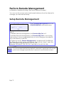
Perform Remote Management
(Available in Wireless Routing Client and Gateway modes)
You can use the access point web-based interface from the Internet to
manage your network remotely.
Setup Remote Management
Step 1:
Select Remote Management from the
CONFIGURATION command menu.
Step 2:
To disable Remote Management, set Remote Http Port to 0
To enable Remote Management, set Remote Http Port to an unused
port number. It is recommended that you avoid using port number 80
as it is blocked by some ISPs.
In Gateway mode, Remote Management is enabled with Port 88 and
the Ethernet port becomes a WAN port. To continue using it, open the
web manager using the WAN IP with Port 88.
Example: For WAN IP 100.100.100.1 use http://100.100.100.1:88
NOTE
It is recommended that the default password is replaced with a new
password changed periodically to prevent unauthorized access.
Page 75
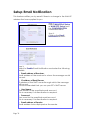
Setup Email Notification
This feature notifies you by email if there is a change in the WAN IP
address that was supplied to you.
Step 1:
Select WAN PPPoE Setup
or WAN PPTP Setup from
the CONFIGURATION
command menu.
Step 2:
Click on the Email
Notification button.
Step 3:
Select to Enable Email Notification and enter the following
details:
• Email address of Receiver:
Email address of the receiver to whom the message would
be sent.
• IP address of Email Server:
IP address of the SMTP server through which the message
will be sent.
It is recommended that you use your ISP’s SMTP server.
• User Name:
User Name for the specified email account.
This is necessary if authentication is required.
• Password:
Pass word for the specified email account.
This is necessary if authentication is required.
• Email address of Sender:
Email address to be displayed as the sender.
Page 76
Step 4:
Specify whether the SMTP server Needs Authentication or
not by setting the checkbox accordingly. By default it is not
selected.
Step 5:
Click on the Apply button.
Page 77
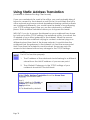
Using Static Address Translation
(Available in Wireless Routing Client mode)
If you use a notebook for work in the office, you most probably bring it
home to connect to the Internet as well. Since it is most likely that your
office network and home network broadband-sharing network subnets
are configured differently, you would have the hassle of reconfiguring
your TCP/IP settings every time you use the notebook in a different
place. Static Address Translation allows you to bypass this hassle.
With SAT, if you try to access the Internet on your notebook from home
but with your office TCP/IP settings, the notebook will try to contact the
IP address of your office gateway to the Internet. When the access
point finds that the notebook is trying to contact a device lying on a
different subnet from that of the home network, it would inform the
notebook that the gateway to the Internet is in fact the access point
itself. From then the notebook would contact the access point for
access to the Internet without any change to the TCP/IP settings.
NOTE
For SAT to function properly:
1. The IP address of the notebook should belong to a different
subnet from the LAN IP address of your access point.
2. The <Default Gateway> in the TCP/IP settings of your
notebook should NOT be left blank.
Step 1:
Select Static Address Translation from the Home User
Features command menu.
Step 2:
Select whether to Enable or
Disable SAT, and click the
Apply button.
SAT is disabled by default.
Page 78
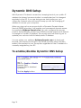
Dynamic DNS Setup
With Dynamic IP Internet connection, keeping track of your public IP
address for Internet communication is complicated as it is changed
regularly by the ISP. If you are doing some web hosting on your
computer, Internet users will have to keep up with the changing IP
address to access your computer.
When you sign up for an account with a Dynamic Domain Name
Service (DDNS) provider, it will register your permanent domain name,
for example: MyName.Domain.com You can configure the access
point to automatically contact your DDNS provider whenever it detects
a change in its public IP address. The access point will then log on to
update your account with its latest public IP address.
If a user enters your address: MyName.Domain.com into their web
browser, this request would go to the DDNS provider which will then
redirect the request to your computer, regardless of the IP address it is
currently assigned by your ISP.
To enable/disable Dynamic DNS Setup
Step 1:
Select Dynamic DNS Setup from the Home User Features
command menu.
Step 2:
Select to Enable or Disable
Dynamic DNS.
Dynamic DNS is disabled
by default.
Click the Apply button.
Page 79
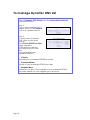
To manage Dynamic DNS List
Step 1:
Select Dynamic DNS Setup from the Home User Features
command menu.
Step 2:
If you have created a list
earlier, click on the Refresh
button to update the list.
Step 3:
To add a new Dynamic
DNS, click on the Add
button.
The Choice DDNS Provider
page appears.
There are two default
providers that you can
use.
The parameters are
explained below:
• Choice:
Indicates your preferred DDNS provider.
• Provider Name:
Name of your preferred DDNS provider.
• Register Now:
Allows you to go to the website of your preferred DDNS
provider where you can register your account.
Page 80
2 DDNS providers are predefined for you. You need to be connected
to the Internet to register your DDNS account.
Select 2MyDNS – Dynamic DNS Service Provider as DDNS Service
Provider:
Step 1:
Under the Choice column in
the Choice DDNS Provider list,
check the radio button next to
the 2MyDNS – DNS Service
Provider entry.
Click on the Next button.
Step 2:
Enter your Domain Name.
Step 3:
The Auto Detect checkbox is
selected by default.
The WAN IP field is empty by
default.
These default settings should
be used if dynamic WAN IP
connection is used.
If your ISP connection uses
dynamic WAN IP:
Select the Auto Detect
checkbox to let the DDNS
server learn your current WAN
IP address.
Enter your DDNS account
Username and Password.
If your ISP connection uses a
fixed WAN IP:
Enter the IP address in the WAN
IP field.
Deselect the Auto Detect
checkbox.
The access point will update
the DDNS server with the
specified WAN IP.
Optional
Your hostname will be allowed
multiple identities if wildcard is
enabled.
For example, if you register:
mydomain.2mydns.net, users
looking for
www.mydomain.2mydns.net or
ftp.mydomain.2mydns.net can
still reach your hostname.
Step 4:
Page 81
Optional
In the Mail Exchanger field,
enter the Static WAN IP
address of the mail server
configured to handle email for
your domain.
Step 5:
Select Backup Mail Exchanger
to enable this service.
Step 6:
Click on the Add button.
The new domain is added to
the Dynamic DNS list table. It
will appear as a hyperlink that
you can click to go back to
the Dynamic DNS Edit page.
Step 7:
From the Dynamic DNS Edit
page you can update or reset
the parameters, or delete the
domain name.
Page 82
Select DtDNS as DDNS Service Provider:
Step 1:
Under the Choice column in
the Choice DDNS Provider list,
check the radio button next to
the DtDNS entry.
Click on the Next button.
Step 2:
Enter your Domain Name.
Step 3:
The Auto Detect checkbox is
selected by default.
The WAN IP field is empty by
default.
These default settings should be
used if dynamic WAN IP
connection is used.
If your ISP connection uses
dynamic WAN IP:
Select the Auto Detect
checkbox to let the DtDNS
server learn your current WAN
IP address.
Enter your DtDNS account
Username and Password.
If your ISP connection uses a
fixed WAN IP:
Enter the IP address in the WAN
IP field.
Deselect the Auto Detect
checkbox.
The access point will update
the DtDNS server with the
specified WAN IP.
Step 4:
Then click on the Add button.
Step 5:
While the new domain name is
being added to the list, the
message ‘Waiting in queue…”
will be displayed under the
Update Status column of the
Dynamic DNS List table.
Page 83
Use the Wireless Extended Features
Set Preferred APs
(Available in Client Mode)
When there is more than one AP with the same SSID, the Preferred APs
function allows you define the MAC address of the APs in order of
preference.
The MAC address at the top of the Preferred APs list has the highest
connection preference, and the MAC address at the bottom has the
lowest connection preference.
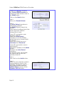
Follow these steps to specify your preferred APs.
Preferred APs
1
1. Click on WLAN Setup from the
CONFIGURATION menu.
2. Select Preferred APs.
2
1. Enter the MAC
addresses of the
preferred APs.
2. Click Apply to effect
the settings.
Page 84
Get Long Distance Parameters
The access point can calculate and display suggested values for
certain parameters to use to ensure that efficient wireless
communication between physically distant access points.
Select Advanced from WLAN Setup under Configuration.
Click on the Long Distance Parameters button under the Extended Features
section.
Select to Enable the Outdoor function.
Page 85
The access point can automatically calculate the values of the parameters to
input based on the distance between your access point and the other wireless
device. Enter the distance in meters and click on the Show Reference Data
button.
You can enter the parameters based on the recommended values in the popup window, click on the Apply button to update the changes.
Long Distance
Parameters
Outdoor
Description
If set to Enable, the Outdoor parameters will be
configured for outdoor communication over short or
long distances as specified, it is disabled by default.
Distance
Determines the distance between your access point
and the remote access point in meters.
Slot Time
The amount of time is divided and each unit of time is
called one slot time.
ACK Timeout
Determines the timeout allowed for the sending client
to receive the acknowledgment response from the
receiving client. If no acknowledgment packet is
received within this period, the sender will assume the
receiver has not received the packet and will attempt
to resend.
CTS Timeout
Clear-to-Send Timeout is the time the wireless sender
will wait for a CTS packet signaling that the channel is
idle and it can start data transmission. If no CTS packet
is received within this period, the sender will assume the
channel is busy and will wait before trying to send
again.
Page 86
Set Wireless Multimedia
Wireless Multimedia (WMM) is a QoS (Quality of Service) standard in
IEEE802.11E that we have adopted to improve and support the user
experience for multimedia, video, and voice applications by prioritizing
data traffic. QoS can be realized through 4 different Access Categories
(AC). Each AC type consists of an independent transmit queue, and a
channel access function with its own parameters.
Page 87
Follow these steps to change the setup Wireless Multimedia on your
access point.
Step 1:
1. Click on WLAN Setup from the CONFIGURATION menu.
2. Select Advanced.
Step 2:
Click on the WMM Settings button.
Step 3:
Select to Enable Wireless Multimedia (WMM)
Enter the desired WMM parameters. Using the default parameters is
recommended.
Click Apply to apply the WMM settings, click Default to reset all parameters to
default, or click Back to discard any changes and return to WLAN Basic Setup
page.
Page 88
WMM Parameters (for advanced users)
AIFs (Arbitrary
Arbitrary Inter-Frame Space is the minimum wait time interval
Inter-Frame
between the wireless medium becoming idle and the start of
Space)
transmission of a frame over the network.
Cwmin
(Contention
Window
Minimum)
Contention Window Minimum is the minimum random wait time
drawn from this interval or window for the backoff mechanism on
the network.
CwMax
(Contention
Window
Maximum)
Contention Window Maximum is the maximum random wait time
drawn from this interval or window for the backoff mechanism on
the network.
TxOp limit
(Transmit
Opportunity
Limit)
Transmit Opportunity limit specifies the minimum duration that an
end-user device can transmit data traffic after obtaining a transmit
opportunity. TxOp limit can be used to give data traffic longer and
shorter access.
NoAck (No
Acknowledge
ment)
No Acknowledgement provides control of the reliability of traffic
flow. Usually an acknowledge packet is returned for every packet
received, increasing traffic load and decreasing performance.
Enabling No Acknowledgement cancels the acknowledgement.
This is useful for data traffic where speed of transmission is important.
ACM
(Admission
Control
Mandatory)
Admission Control Mandatory enables WMM on the radio interface.
When ACM is enabled, associated clients must complete the WMM
admission control procedure before access.
BE (Best Effort)
Parameters for Data0 Best Effort.
Best Effort data traffic has no prioritization and applications equally
share available bandwidth.
BK
(Background)
Parameters for Data1 Background.
Background data traffic is de-prioritized and is mostly for backup
applications, or background transfers like backup applications or
background transfers like bulk copies that do not impact ongoing
traffic like Internet downloads.
VI (Video)
Parameters for video data traffic.
VO (Voice)
Parameters for voice data traffic.
Page 89
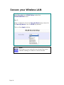
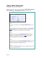
Secure your Wireless LAN
Step 1:
Select Security from WLAN Setup under the
CONFIGURATION menu.
Step 2:
Make a selection from the Security Mode drop-down list.
The Security Mode is set to NONE by default.
Click on the Apply button.
NOTE
All nodes in your network must share the same
wireless settings in order to communicate.
Page 90
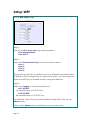
Setup WEP
At the WEP Setup page,
Step 1:
Specify the key entry type, by selecting either:
• Use Hexadecimal:
• Use ASCII
Step 2:
Select the Transmission Key from the pull down menu:
• Key 1
• Key 2
• Key 3
• Key 4
The access point lets you define up to four different transmission keys.
It defines a set of shared keys for network security. You must enter at
least one WEP key to enable security using a shared key.
Step 2:
Select the length of each encryption key:
• 64- bit WEP
10 hexadecimal or 5 ASCII Text
• 128-bit WEP
26 hexadecimal or 13 ASCII Text
To clear the values that you have entered in the field, click on the
Reset button.
Click on the Apply button and reboot your access point.
Page 91
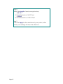
Setup WPA-Personal
(Available in Access Point mode)
Follow these steps if you have activated the WPA-Personal, WPA2Personal or WPA-Personal-AUTO security modes.
At the WPA1/2-PSK Setup page,
Step 1:
Specify the key entry type, by selecting either:
• Passphrase (Alphanumeric characters)
• Hexadecimal
Step 2:
Fill in the pre-shared network key:
If you are using the Passphrase format, your entry can
consist of a minimum of 8 alphanumeric characters or a
maximum of 63 alphanumeric characters.
Otherwise, when using the Hexadecimal format, your
entry MUST consist of 64 hexadecimal characters.
Page 92
Step 3:
For WPA-Personal
Set the Cipher Type to TKIP.
WPA replaces WEP with a strong encryption technology
called Temporal Key Integrity Protocol (TKIP) with
Message Integrity Check (MIC).
For WPA2-Personal
Set the Cipher Type to AES.
Advanced Encryption Standard (AES) is a stronger
symmetric 128-bit block data encryption technique. AES is
a requirement of WPA2 under the IEEE 802.11i standard.
For WPA-Personal-AUTO
Set the Cipher Type to Auto to allow the access point to
automatically detect the cipher type to use.
Step 4:
Enter the GTK (Group Transient Key) Updates.
This is the length of time after which the access point will
automatically generate a new shared key to secure
multicast/broadcast traffic among all stations that are
communicating with it. By default, the value is 600
seconds.
Step 5:
Click the Apply button and reboot your system, after
which your settings will become effective.
Page 93
Setup 802.1x/RADIUS
(Available in Access Point mode)
At the IEEE 802.1x Setup page,
Step 1:
Key in the IP address of the Primary RADIUS Server in your
WLAN. You can optionally add in the IP address of a
Secondary RADIUS Server, if any.
The RADIUS authentication server MUST be in the same
subnet as the access point.
Step 2:
By default, the value for Authentication Port number is
1812. You can leave this value as it is. This value must be
set to be the same as the one in the RADIUS server.
Step 3:
By default, the value for Accounting Port number is 1813.
You can leave this value as it is. This value must be set to
be the same as the one in the RADIUS server.
Step 4:
Enter the Shared Secret Key in the field provided.
Step 5:
By default, the Broadcast Key Rotation is set as 600
seconds. You may leave this value as its default setting.
Page 94
Step 6:
Select the length of each encryption key:
• 64- bit
10 hexadecimal or 5 ASCII Text
• 128-bit
26 hexadecimal or 13 ASCII Text
Step 7:
Click the Apply button and reboot your system, after
which your settings will become effective.
Page 95
Setup WPA Enterprise
(Available in Access Point mode)
Follow these steps if you have selected the WPA, WPA1-Enterprise,
WPA2-Enterprise, or WPA-Enterprise-AUTO security modes.
At the WPA1/2-EAP Setup page,
Step 1:
Key in the IP address of the Primary RADIUS Server in your
WLAN.
You can optionally add in the IP address of a Secondary
RADIUS Server, if any. The RADIUS authentication server
MUST be in the same subnet as the access point.
Step 2:
By default, the value for Authentication Port number is
1812. You can either leave this value as it is or key in a
different Authentication Port but it MUST match the
corresponding port of the RADIUS server.
Step 3:
By default, the value for Accounting Port is 1813. You can
leave this value as it is. This value must be set to be the
same as the one in the RADIUS server.
Step 4:
Enter the Shared Secret Key used to validate client-server
RADIUS communications.
Page 96
Step 5:
Select the length of each encryption key:
• 64- bit
10 hexadecimal or 5 ASCII Text
• 128-bit
26 hexadecimal or 13 ASCII Text
Step 6:
For WPA-Enterprise
Set the Cipher Type to TKIP.
WPA replaces WEP with a strong encryption technology
called Temporal Key Integrity Protocol (TKIP) with
Message Integrity Check (MIC).
For WPA2- Enterprise
Set the Cipher Type to AES.
Advanced Encryption Standard (AES) is a symmetric 128bit block data encryption technique. It is a requirement of
WPA2 under the IEEE 802.11i standard.
For WPA- Enterprise -AUTO
Set the Cipher Type to Auto to allow the access point to
automatically detect the cipher type to use.
Step 7:
Enter the GTK (Group Transient Key) Updates.
This is the length of time after which the access point will
automatically generate a new shared key to secure
multicast/broadcast traffic among all stations that are
communicating with it. By default, the value is 600
seconds.
Step 8:
Click the Apply button and reboot your system, after
which your settings will become effective.
Page 97
Configure the Security Features
Use Packet Filtering
Packet filtering selectively allows /disallows applications from Internet
connection.
Configure Packet Filtering
Step 1:
Select Packet Filtering from the Security Configuration command menu.
Step 2:
Select the Packet Filter Type by
clicking on the Change button.
Step 3:
Select from three choices: Disabled,
Sent, Discarded, and then click on the
Apply button. The default is Disabled,
which allows all packets to be sent.
Step 4:
Click on the Add button and you will be
able to define the details of your Packet
Filter Rule from the screen on the right.
4a). Enter Rule Name for this new
packet filtering rule. For example,
BlockCS
4b). From the IP Address drop down
list, select whether to apply the
rule to:
Page 98
A Range of IP addresses
In this case, you will have to define
(From) which IP address (To) which
IP address, your range extends.
A Single IP address
Here, you need only specify the
source IP address in the (From)
field.
Any IP address
You may here, leave both, the
(From) as well as the (To) fields,
blank. Here, the rule will apply to
all IP addresses.
4c). At the Destination Port drop down
list, select either:
A Range of TCP ports
In this case, you will have to define
(From) which port (To) which port,
your rule applies.
A Single TCP port
Here, you need only specify the
source port in the (From) field.
Any IP port
You may here, leave both, the
(From) as well as the (To) fields,
blank. Here, the rule will apply to
all ports.
4d). From the Day of the Week drop
down list, select whether the rule
should apply to:
A Range of days
Here, you will have to select (From)
which day (To) which day
Any day
In this case, you may skip both the
(From) as well as the (To) drop
down fields.
Page 99
4e). At the Time of the Day drop down
list, you may also choose to apply
the rule to:
A Range of time
In which case, you have to specify
the time in the format HH:MM,
where HH may take any value
from 00 to 23 and MM, any value
from 00 to 59.
Any time
Here, you may leave both (From)
and (To) fields blank.
Step 5:
Click on the Apply button to make the
new rule effective.
The Filtering Configuration table will then
be updated.
Step 6:
In this example, we would block an
application called CS from all PCs
(any IP address within the network)
from Monday to Friday 7am to
6pm, and this application is using
the port number 27015.
Therefore, for a rule we name
BlockCS, and add the entries
depicted on the left. Clicking on
the Add button will effect your
packet filter rule.
Page 100
Use URL Filtering
URL Filtering allows you to block objectionable websites from your LAN
users.
Configure URL Filtering
Step 1:
Select URL Filtering from the Security Configuration
command menu.
Step 2:
To select the URL Filter Type,
click the Change button.
Step 3:
Select to Block or Allow,
and then click on the
Apply button. The default
is Disabled, which allows all
websites to be accessed.
Then click the Add button.
Step 4:
For the Host Name field, input
the web site address that you
wish to block. Then click the
Add button to complete your
setup.
Page 101
Configure the Firewall
Configure SPI Firewall
Stateful Packet Inspection (SPI) thwarts common hacker attacks like IP
Spoofing, Port Scanning, Ping of Death, and SynFlood by comparing
certain key parts of the packet to a database of trusted information
before allowing it through.
NOTE
Firewall security rules should be planned carefully as incorrect
configuration may cause improper network function.
Select Firewall Configuration from the Security Configuration command menu.
Enable the firewall. You can choose among the Default Low, Default Medium or
Default High security options for convenient setup.
Then you may choose the type of network activity information you wish to log
for reference. Data activity arising from different types of protocol can be
recorded.
Page 102
You may add more firewall rules for specific security purposes. Click on the Add
radio button at the screen shown above, followed by the Edit button.
Rule
: Enter a unique name to identify this firewall rule.
Name
Disposition : This parameter determines whether the packets obeying the rule
Policy
should be accepted or denied by the firewall. Choose between
Accept and Deny.
Protocols
: Users are allowed to select the type of data packet from: TCP,
UDP, ICMP, IGMP or ALL.
Note: If users select either ICMP or IGMP, they are required to
make further selection in the ICMP Types or IGMP Types
respectively.
ICMP
Types
: This IP protocol is used to report errors in IP packet routing. ICMP
serves as a form of flow control, although ICMP messages are
neither guaranteed to be received or transmitted.
ICMP
Packet Type
Echo
request
Echo reply
Page 103
Description
Determines whether an IP
node (a host or a router) is
available on the network.
Replies to an ICMP echo
request.
Destination
unreachabl
e
Source
quench
Redirect
Time
exceeded
Parameter
Problem
Timestamp
Request
Information
Request
Information
Reply
IGMP
Types
Source IP
Informs the host that a
datagram cannot be
delivered.
Informs the host to lower the
rate at which it sends
datagrams because of
congestion.
Informs the host of a
preferred route.
Indicates that the Time-toLive (TTL) of an IP datagram
has expired.
Informs that host that there
is a problem in one the
ICMP parameter.
Information that is from the
ICMP data packet.
Information that is from the
ICMP data packet.
Information that is from the
ICMP data packet.
: This IP protocol is used to establish host memberships in particular
multicast groups on a single network. The mechanisms of the
protocol allow a host to inform its local router, using Host
Membership Reports.
Host
Information that is from the
Membership IGMP data packet.
Report
Host
Information that is from the
Membership IGMP data packet.
Query
Leave Host
Information that is from the
Message
ICMP data packet.
: This parameter allows you to specify workstation(s) generating
the data packets. Users can either set a single IP address or set a
range of IP addresses.
Destinatio
n IP
: This parameter lets you specify the set of workstations that
receive the data packets. Users can either set a single IP address
or set a range of IP addresses.
Source
Port
: You can control requests for using a specific application by
entering its port number here. Users can either set a single port
number or a range of port numbers.
Page 104
Destinatio
n Port
: This parameter determines the application from the specified
destination port. Users can either set a single port number or a
range of port numbers.
Check
Options
: This parameter refers to the options in the packet header. The
available selection options are abbreviated as follows:
SEC – Security
LSRR – Loose Source Routing
Timestamp – Timestamp
RR – Record Route
SID – Stream Identifier
SSRR – Strict Source Routing
RA – Router Alert
Check TTL
: This parameter would let you screen packets according to their
Time-To-Live (TTL) value available options are:
1. Equal
2. Less than
3. Greater than
4. Not equal
Page 105
Use the Firewall Log
The Firewall Log captures and stores network traffic information such as
the type of data traffic, the time, the source and destination address /
port, as well as the action taken by the firewall.
View Firewall Logs
Step 1:
Select Firewall Log from the SECURITY CONFIGURATION command menu.
Step 2:
Click on the Refresh button to see the
information captured in the log:
Page 106
Time at which the packet was
detected by the firewall.
Action, which states whether the
packet was accepted or denied.
Protocol type of the packet.
Source Address from which the
packet originated
Destination Address to which the
packet was intended.
Source Port from which the packet
was initiated.
Destination Port to which the packet
was meant for.
Any Information.
Administer the System
Use the System Tools
Use the Ping Utility
(Available in Wireless Routing Client and Gateway modes.)
You can check whether the access point can communicate (ping)
with another network host with the Ping Utility.
Step 1:
Select Ping Utility under the SYSTEM TOOLS command
menu.
Step 2:
Enter the IP address of the
target host to ping.
Click the Start button.
The Ping messages are displayed.
Page 107
Use Syslog
Syslog forwards system log messages in a network to a machine
running a Syslog listening application. It is used to help in managing the
computer system and increase security on the network.
Freeware supporting Syslog is widely available for download from the
Internet.
This section shows how to:
• Setup Syslog.
• View logged information.
The System Log Setup page allows the user to:
• Enable or Disable system logging.
• Set the Remote IP Address or Domain Name and Remote Port for
the router to send the system log messages to.
Page 108
Follow these steps to setup Syslog:
Step 1:
Click on Syslog from the SYSTEM TOOLS menu.
Step 2:
Select to Enable Syslog.
Enter the Logging IP or Domain Name
Enter the Logging Port
Click Apply to make the changes.
Page 109
Follow these sample steps to view logged information:
Step 1:
Search for a Syslog listening application.
Step 2:
Select a Syslog listening application.
Step 3:
Download Syslog listening application.
Step 4:
Install Syslog listening application.
Step 5:
View logged information on Syslog listening application.
Page 110
Set System Identity
You can set the System Identity of the access point to be uniquely
identifiable.
Step 1:
Select System Identity from the SYSTEM TOOLS menu.
Step 2:
Enter a unique System Name.
Step 3:
Enter the name of a contact person in the System
Contact field.
Step 4:
Enter the System Location.
This entry identifies the device location, especially when
there are multiple devices.
Step 5:
Click on the Apply button to effect the changes.
Page 111
Setup System Clock
Step 1:
Select System Clock Setup from the SYSTEM TOOLS menu.
Step 2:
Select the appropriate time zone from the Select to
Change the Time Zone for the Router Location drop-down
list.
Step 3:
Enable the Auto Time Setting (SNTP) radio button. SNTP
stands for Simple Network Time Protocol and is used to
synchronise computer clocks.
Step 4:
Fill in the Time Servers field and click on the Apply button
to effect the changes.
Page 112
Upgrade the Firmware with uConfig
You can check the types and version of your firmware by clicking on
About System from the HELP menu.
To begin with, ensure that you have the updated firmware available.
Step 1:
Select Firmware Upgrade from the SYSTEM TOOLS menu.
Step 2:
Click on the Browse button to locate the file.
Step 3:
Click on the Upgrade button.
Follow the instructions given during the upgrading
process.
Step 4:
You need to reboot the system after the firmware
upgrade.
Page 113
NOTE
The firmware upgrade process must NOT be
interrupted; otherwise the device might become
unusable.
Page 114
Upgrade the Firmware with Command Line
Interface
You can check the types and version of your firmware by clicking on
About System from the HELP menu in UConfig.
Follow these steps to upgrade firmware from Command Line Interface
(CLI).
Step 1:
Ensure that you have the updated firmware available.
Page 115
Step 2:
On the PC connected to the AP, run a TFTP server and
setup to point to the same firmware image filename.
Sample Screenshot
Step 3:
In the Command Line Interface, enter the command with
the IP address of the AP and the filename of the firmware
image as the parameters:
Set upgrade <IP address of AP> <firmware image
filename>
Page 116
Step 4:
These screens display when upgrade is done.
Sample Screenshot
NOTE
The firmware upgrade process must NOT be
interrupted; otherwise the device might become
unusable.
Page 117
Perform Firmware Recovery
If the system fails to launch properly, the access point will automatically
switch to loader mode and the diagnostic LED will remain lighted. The
firmware should then be reloaded.
Access Point State
Corrupted firmware – access point
automatically switches to loader
mode
Recovery in progress
Successful recovery
Diagnostic LED ( )
State
Blinks very fast
ON
Blinks very slowly
Before starting, check the status of the diagnostic LED to confirm if
firmware failure has occurred.
Step 1:
Stop power supply and disconnect the access point from
the network.
Step 2:
Connect the LAN port of the access point to the LAN port
of your computer with an MDI cable.
Step 3:
Power on the access point, and start up your computer.
You are recommended to set your computer’s IP address
to 192.168.168.100 and its network mask to 255.255.255.0.
It is recommended that your computer IP address is set to
192.168.168.100 and the network mask is set to
255.255.255.0
Step 4:
Insert the Product CD into the CD drive of your computer.
Page 118
Step 5:
From the Start menu, click Run and type cmd. When the
command prompt window appears, type in the following
command:
X:\recovery\TFTP -i 192.168.168.1 PUT image_name.IMG,
where X refers to your CD drive and image_name.IMG
refers to the firmware filename found in the Recovery
folder of the Product CD.
Step 6:
If you have downloaded a newer firmware and have
saved it in your local hard disk as:
C:\accesspoint\accesspointxxx.IMG, then replace the
command with this new path and firmware name. For
example:
C:\accesspoint\TFTP –i 192.168.168.1 PUT
accesspointxxx.img
The recovery process takes place.
You can monitor the progress of the recovery process
with the diagnostic LED.
When firmware restoration is complete, reboot the access
point and it will be ready to operate.
Page 119
Backup or Reset the Settings
You may choose to save the current configuration profile, create a
backup of it on your hard disk, restore an earlier saved profile, or to
reset the access point back to its default settings.
Reset your settings
Step 1:
Select Backup or Reset Settings from the SYSTEM TOOLS
menu.
Step 2:
To discard configurations made and restore the access
point to its initial factory settings, click on the Reset
button.
Step 3:
The system will prompt you to reboot your device, click on
the Reboot button.
Page 120
Backup your Settings
Step 1:
Select Backup or Reset Settings from the SYSTEM TOOLS
menu.
Step 2:
To back up the current settings of your access point onto
your hard disk drive, click on the Backup button.
Step 3:
Save your configuration file to your local disk.
Page 121
Restore your Settings
Step 1:
Select Backup or Reset Settings from the SYSTEM TOOLS
menu.
Step 2:
To restore previously saved settings, click on the Browse…
button and select the folder where you saved your
configuration file.
Click on the Restore button and the system will prompt
you to reboot your device.
Page 122
Reboot the System
Most of the changes you make to the system settings require a system
reboot before the new parameters can take effect.
Step 1:
Select Reboot System from the SYSTEM TOOLS menu.
Step 2:
Click on the Reboot button.
Step 3:
Wait for the system to reboot and the login page will be
displayed.
Page 123
Change the Password
It is recommended that the login password is changed from the factory
default password.
Step 1:
Select Change Password from the SYSTEM TOOLS menu.
Step 2:
Key in the Current Password. The password is casesensitive and defaulted to password
Enter the New Password field and then Confirm Password.
Step 3:
Click on the Apply button to update the changes.
Page 124
To Logout
Step 1:
Select Logout from the SYSTEM TOOLS menu.
Step 2:
Click the LOGIN! button to access the access point
configuration interface again.
Page 125
Use the HELP menu
View About System
System Information displays system configuration information that may
be required by support technicians for troubleshooting.
Select About System from the HELP menu.
The System Information page displays information about
the access point configuration settings.
Page 126
Appendix: Use the Command Line
Interface
Get Operation List
SYNTAX
Get tasks
Get sysinfo
Get aplist
Get athstats
Get brinfo
Get brmacshow
Get bssinfo.
Get channel
Get chanlist
Get ieee80211stats
Get routeshow
Get stalist
Get linkinfo
Get macstats
Get opmode
Get wmode
DESCRIPTION
Display all active process/tasks.
Display system information.
Display list of access points discovered.
Display wireless driver information.
Display bridge and interfaces information.
Display bridge learned MAC address list.
Display current radio information.
Display current wireless channel number.
Display current domain wireless channels.
Display ieee80211 protocol statistics.
Display the routing table information.
Display a list of currently associated stations.
Display client link information (Client mode only)
Display a list of currently learnt wireless device MAC addresses.
Display current wireless operation mode.
Display wireless mode
Set Operation List
SYNTAX
Set factorydefault
Restart
DESCRIPTION
Set factorydefault – restore configuration to factory default.
Do a warm reboot.
Save Configuration
SYNTAX
Commit
DESCRIPTION
Save current configuration to flash.
Most commands require rebooting to take effect after saving.
Long Range
Check for recommended values from long distance option setup page.
SYNTAX
DESCRIPTION
Set outdoor <enable/disable>
Enable outdoor for long-range connection.
Set distance <value>
Set the connection distant (value in decimal)
Set acktimeout <value>
Set the ACK timeout (value in decimal)
Set ctstimeout <value>
Set the CTS timeout (value in decimal)
Set slottimeout <value>
Set the Slot timeout (value in decimal)
TX Power
SYNTAX
Set txpower <string>
TX Rate
SYNTAX
Set txrate <string>
Page 127
DESCRIPTION
(Default full) auto, 1, 2, 3, 4, ..., 17, full, min
DESCRIPTION
Values are: (default auto)
(802.11a)-- 6, 9, 12, 18, 24, 36, 48, 54, auto (Version AG)
(802.11b/g mixed)-- 1, 2, 5,5, 11, 6, 9, 12, 18, 24, 36, 48, 54, auto
(802.11b-only)-- 1, 2, 5.5, 11, auto
Wireless Mode
SYNTAX
Set wirelessmode <string>
Set autochannelselect Enable/disable
Set radio_off_eth_down enable/disable
DESCRIPTION
Supported strings are: auto, 11a, 11b, 11g, pureg, superg, supera
Enable or disable smart channel select during power up.
Enable or disable auto turn off radio when Ethernet port connection link is lost.
WEP Key
Must first set a key entry type, and then proceed to set the key index, size, and value.
SYNTAX
DESCRIPTION
Set key <keyindex> <keysize> <keyvalue>
Set keyentrymethod hex/ascii
Set key <keyindex> default
Set default key.
Add or Delete User
SYNTAX
Set user < [-r|-w] > <password> username
Set user –d username
Country Code
SYNTAX
Set countrycode <iso.name>
Set countrycode <2 letter string>
Page 128
DESCRIPTION
To add a user.
To delete user.
DESCRIPTION
List of countries:
{0,
"NA" },
{CTRY_ALBANIA, "AL" },
{CTRY_ALGERIA, "DZ" },
{CTRY_ARGENTINA, "AR" },
{CTRY_ARMENIA, "AM" },
{CTRY_AUSTRALIA, "AU" },
{CTRY_AUSTRIA, "AT" },
{CTRY_AZERBAIJAN, "AZ" },
{CTRY_BAHRAIN, "BH" },
{CTRY_BELARUS, "BY" },
{CTRY_BELGIUM, "BE" },
{CTRY_BELIZE,
"BZ" },
{CTRY_BOLIVIA, "BO" },
{CTRY_BRAZIL,
"BR" },
{CTRY_BRUNEI_DARUSSALAM, "BN" },
{CTRY_BULGARIA, "BG" },
{CTRY_CANADA,
"CA" },
{CTRY_CHILE,
"CL" },
{CTRY_CHINA,
"CN" },
{CTRY_COLOMBIA, "CO" },
{CTRY_COSTA_RICA, "CR" },
{CTRY_CROATIA, "HR" },
{CTRY_CYPRUS,
"CY" },
{CTRY_CZECH,
"CZ" },
{CTRY_DENMARK,
"DK" },
{CTRY_DOMINICAN_REPUBLIC, "DO" },
{CTRY_ECUADOR, "EC" },
{CTRY_EGYPT,
"EG" },
{CTRY_EL_SALVADOR, "SV" },
{CTRY_ESTONIA, "EE" },
{CTRY_FINLAND, "FI" },
{CTRY_FRANCE,
"FR" },
{CTRY_FRANCE2, "F2" },
{CTRY_GEORGIA, "GE" },
{CTRY_GERMANY, "DE" },
{CTRY_GREECE,
"GR" },
{CTRY_GUATEMALA, "GT" },
{CTRY_HONDURAS, "HN" },
{CTRY_HONG_KONG, "HK" },
{CTRY_HUNGARY, "HU" },
{CTRY_ICELAND, "IS" },
{CTRY_INDIA,
"IN" },
{CTRY_INDONESIA, "ID" },
{CTRY_IRAN,
"IR" },
{CTRY_IRELAND, "IE" },
{CTRY_ISRAEL,
"IL" },
{CTRY_ITALY,
"IT" },
{CTRY_JAPAN,
"JP" },
{CTRY_JAPAN1,
"J1" },
{CTRY_JAPAN2,
"J2" },
{CTRY_JAPAN3,
"J3" },
{CTRY_JAPAN4,
"J4" },
{CTRY_JAPAN5,
"J5" },
{CTRY_JAPAN6,
"J6" },
{CTRY_JORDAN,
"JO" },
{CTRY_KAZAKHSTAN, "KZ" },
{CTRY_KOREA_NORTH, "KP" },
{CTRY_KOREA_ROC, "KR" },
{CTRY_KOREA_ROC2, "K2" },
{CTRY_KOREA_ROC3, "K3" },
{CTRY_KUWAIT,
"KW" },
{CTRY_LATVIA,
"LV" },
{CTRY_LEBANON, "LB" },
{CTRY_LIECHTENSTEIN, "LI" },
{CTRY_LITHUANIA, "LT" },
{CTRY_LUXEMBOURG, "LU" },
{CTRY_MACAU,
"MO" },
{CTRY_MACEDONIA, "MK" },
{CTRY_MALAYSIA, "MY" },
{CTRY_MALTA,
"MT" },
{CTRY_MEXICO,
"MX" },
{CTRY_MONACO,
"MC" },
{CTRY_MOROCCO, "MA" },
{CTRY_NETHERLANDS, "NL" },
{CTRY_NEW_ZEALAND, "NZ" },
{CTRY_NORWAY,
"NO" },
{CTRY_OMAN,
"OM" },
{CTRY_PAKISTAN, "PK" },
{CTRY_PANAMA,
"PA" },
{CTRY_PERU,
"PE" },
{CTRY_PHILIPPINES, "PH" },
{CTRY_POLAND,
"PL" },
{CTRY_PORTUGAL, "PT" },
{CTRY_PUERTO_RICO, "PR" },
{CTRY_QATAR,
"QA" },
{CTRY_ROMANIA, "RO" },
{CTRY_RUSSIA,
"RU" },
{CTRY_SAUDI_ARABIA, "SA" },
{CTRY_SINGAPORE, "SG" },
{CTRY_SLOVAKIA, "SK" },
{CTRY_SLOVENIA, "SI" },
{CTRY_SOUTH_AFRICA, "ZA" },
{CTRY_SPAIN,
"ES" },
{CTRY_SWEDEN,
"SE" },
{CTRY_SWITZERLAND, "CH" },
{CTRY_SYRIA,
"SY" },
{CTRY_TAIWAN,
"TW" },
{CTRY_THAILAND, "TH" },
{CTRY_TRINIDAD_Y_TOBAGO, "TT" },
{CTRY_TUNISIA, "TN" },
{CTRY_TURKEY,
"TR" },
{CTRY_UKRAINE, "UA" },
{CTRY_UAE,
"AE" },
{CTRY_UNITED_KINGDOM, "GB" },
{CTRY_UNITED_STATES, "US" },
{CTRY_URUGUAY, "UY" },
{CTRY_UZBEKISTAN, "UZ" },
{CTRY_VENEZUELA, "VE" },
{CTRY_VIET_NAM, "VN" },
{CTRY_YEMEN,
"YE" },
{CTRY_ZIMBABWE, "ZW" },
Page 129
Channel
SYNTAX
Set channel <value>
DESCRIPTION
(Value in decimal)
SSID
SYNTAX
Set ssid <string>
DESCRIPTION
(Not More than 32 characters)
Closed System
SYNTAX
Set hidessid enable/disable
DESCRIPTION
Enable or disable broadcasting of SSID.
Per Node
SYNTAX
Set apbridge enable/disable
DESCRIPTION
Enable or disable isolation of wireless client.
RTS, Fragment, and Beacon Interval
SYNTAX
DESCRIPTION
Set rts <value
(Value in decimal, default 2312, range 1 to 2312)
Set fragment <value>
(Value in decimal, default 2346, range, 256 to 2346)
Set beaconintval <value>
(Value in decimal, default 1, range 1 to 1000)
Set dtim <value>
Data Beacon Rate (value in decimal, default 1, range 1 to 16384)
WLAN State
SYNTAX
Get wlanstate
Set wlanstate enable/disable
DESCRIPTION
Display whether status of current wireless operation is Enabled or Disabled.
Set to Disable to turn off wireless operation.
Set to Enable to turn back on wireless operation.
Note:
When executing this command, please ensure that you are not connected on
wireless with device or you will be disconnected from the device and network.
The wireless operation can only be Enabled from the Ethernet port or UTP cable
connection to device.
Reset Button
SYNTAX
Get buttonpassreset
Set buttonpassreset enable/disable
Upgrade Firmware
SYNTAX
DESCRIPTION
Page 130
DESCRIPTION
Display the status of Reset Button operation.
If status is (Enabled), resetting of password by pressing Reset Button is allowed.
If status is (Disabled), resetting of password by pressing Reset Button is not allowed.
Set to Disable to prevent resetting of password by pressing Reset button.
Set to Enable to allow resetting of password by pressing Reset button.
Set upgrade <IP address of AP> <firmware image filename>
To upgrade firmware in CLI enter this command with the IP address of AP and the
firmware image filename.
Custom Configuration Update
SYNTAX
Cfgfile <operation type> <IP of PC running TFTP server> <filename>
DESCRIPTION
The cfgfile command is used for managing simple configuration changes to multiple access points.
It is useful for when the user has many access points to configure and the configuration is mostly the same.
For example if user needs to configure ten access points, and just change the IP address configuration:
1.
Configure the first access point with the common configuration for all the access points
using web manager
2.
Export the access point configuration file with cfgfile in Telnet.
3.
Edit the IP addresses in the access point configuration files to customise them for the
individual access points.
4.
Import the edited access point configuration files to the respective access points with
cfgfile in Telnet.
Requirement and Explanation:
The cfgfile command uses the TFTP (Trivial File Transfer Protocol). This command transfers the access point
configuration file to and from the access point. It has 4 operation types for these transfers – Backup,
Restore, Export, and Import.
Before executing the cfgfile command, there are some requirements that have to be met in order for the
command to execute successfully. The TFTP server has to be running on the PC with the Telnet connection
to the access point.
Make a note of the directory where the access point configuration file is located in. This directory can be
a folder on the hard drive of the PC with the Telnet connection. It can also be any storage device that is
connected o this PC. The TFTP server has to be set up to point to this directory.
This table explains the different Operation Types.
Operation Type
Backup
The Backup operation saves the configuration from the access point to the configuration file
defined in <filename> and stored on the PC.
This is a binary file (*.bin) which must not be edited as doing so will corrupt it.
(Access Point Æ PC)
Restore
The Restore operation returns the access point back to the previous configuration according
to the configuration file defined in <filename> on the PC.
This is a binary file (*.bin) which must not be edited as doing so will corrupt it.
(PC Æ Access Point)
Export
The Export operation extracts a portion of the access point configuration to a text file on the
PC which can be edited to further customise it for each access point.
This text file can then be imported into other access points with the Import cfgfile operation.
(Access Point Æ PC)
Import
The Import Operation uploads the configuration to the access point.
This configuration is the access point configuration which has been exported previously with
the Export cfgfile operation and then further edited to customise for each access point.
(PC Æ Access Point)
Page 131
Page 132