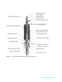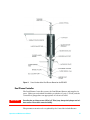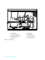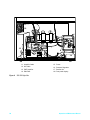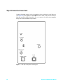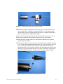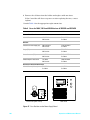
1
Agilent 355 Sulfur and 255 Nitrogen Chemiluminescence Detectors Operation and Maintenance Manual Agilent Technologies Notices © Agilent Technologies, Inc. 2012 Manual Part Number No part of this manual may be reproduced in any form or by any means (including electronic storage and retrieval or translation into a foreign language) without prior agreement and written consent from Agilent Technologies, Inc. as governed by United States and international copyright laws. G6600-90006 Acknowledgements Agilent Technologies, Inc. 2850 Centerville Road Wilmington, DE 19808-1610 USA Torx® is a registered trademark of Textron Inc.; Kimwipe® is a registered trademark of the Kimberly-Clark Corporation. Edition Second edition, November 2012 First edition, June 2007 Replaces G6600-90002 Printed in USA Warranty The material contained in this document is provided “as is,” and is subject to being changed, without notice, in future editions. Further, to the maximum extent permitted by applicable law, Agilent disclaims all warranties, either express or implied, with regard to this manual and any information contained herein, including but not limited to the implied warranties of merchantability and fitness for a particular purpose. Agilent shall not be liable for errors or for incidental or consequential damages in connection with the furnishing, use, or performance of this document or of any information contained herein. Should Agilent and the user have a separate written agreement with warranty terms covering the material in this document that conflict with these terms, the warranty terms in the separate agreement shall control. Technology Licenses The hardware and/or software described in this document are furnished under a license and may be used or copied only in accordance with the terms of such license. Restricted Rights Legend If software is for use in the performance of a U.S. Government prime contract or subcontract, Software is delivered and licensed as “Commercial computer software” as defined in DFAR 252.227-7014 (June 1995), or as a “commercial item” as defined in FAR 2.101(a) or as “Restricted computer software” as defined in FAR 52.227-19 (June 1987) or any equivalent agency regulation or contract clause. Use, duplication or disclosure of Software is subject to Agilent Technologies’ standard commercial license terms, and non-DOD Departments and Agencies of the U.S. Government will receive no greater than Restricted Rights as defined in FAR 52.227-19(c)(1-2) (June 1987). U.S. Government users will receive no greater than Limited Rights as defined in FAR 52.227-14 (June 1987) or DFAR 252.227-7015 (b)(2) (November 1995), as applicable in any technical data. Safety Notices CAUTION A CAUTION notice denotes a hazard. It calls attention to an operating procedure, practice, or the like that, if not correctly performed or adhered to, could result in damage to the product or loss of important data. Do not proceed beyond a CAUTION notice until the indicated conditions are fully understood and met. WA R N I N G A WARNING notice denotes a hazard. It calls attention to an operating procedure, practice, or the like that, if not correctly performed or adhered to, could result in personal injury or death. Do not proceed beyond a WARNING notice until the indicated conditions are fully understood and met. Warnings English WA R N I N G This symbol on the instrument indicates that the user should refer to the manual for operating instructions. WA R N I N G Any operation requiring access to the inside of the equipment, could result in injury. To avoid potentially dangerous shock, disconnect from power supply before opening the equipment. WA R N I N G For continued protection against fire hazard replace fuse with same type and rating. WA R N I N G This symbol indicates that to comply with European Union Directive 2002/96/EC for waste electrical and electronic equipment (WEEE), the Analyzer should be disposed of separately from standard waste. WA R N I N G This is a safety Class I product. It must be wired to a mains supply with a protective earthing ground incorporated into the power cord. Any interruption of the protective conductor, inside or outside the equipment, is likely to make the instrument dangerous. Intentional interruption is prohibited. WA R N I N G If this instrument is used in a manner not specified by Agilent, the protection provided by the instrument may be impaired. WA R N I N G High voltage is present in the instrument when the power cord is connected, even if the main power switch is in the standby mode. To avoid potentially dangerous shock, disconnect the power cord before removing the side panels. Operation and Maintenance Manual 3 4 WA R N I N G Ozone is a hazardous gas and a strong oxidant. Exposure to ozone should be minimized by using the instrument in a well-ventilated area and by venting the exhaust of the vacuum pump to a fume hood. The ozone generator should be turned off when the instrument is not in use. WA R N I N G Burner temperature Is extremely hot. Do not touch. Allow to cool before servicing. WA R N I N G Hydrogen is an extremely flammable gas. Use appropriate care when handling. Inspect all connections with a suitable leak detector. WA R N I N G Oxygen rich environments can promote combustion and even result in spontaneous combustion under conditions of high pressure and exposure to contamination. Use only oxygen rated components and ensure that components are oxygen clean prior to use with pure oxygen. WA R N I N G Exceeding the gas inlet pressure of 25 psig (1.72 bar) may damage the hydrogen and oxidant sensors or burst their connective tubing. Operation and Maintenance Manual Español WA R N I N G Cualquier operación que requiera acceso al interior del equipo, puede causar una lesión. Para evitar peligros potenciales, desconectarlo de la alimentación a red antes de abrir el equipo. WA R N I N G Para protección contínua contra el peligro de fuego, sustituir el fusible por uno del mismo tipo y características. WA R N I N G Este símbolo en el instrumento indica que el usuario debería referirse al manual para instrucciones de funcionamiento. WA R N I N G Esto es un producto con clase I de seguridad. Debe conectarse a una red que disponga de tierra protectora en el cable de red. Cualquier interrupción del conductor protector, dentro o fuera del equipo, puede ser peligroso. Se prohibe la interrupción intencionada. WA R N I N G Si este instrumento se usa de una forma no especificada por Agilent, puede desactivarse la protección suministrada por el instrumento. Operation and Maintenance Manual 5 Français 6 WA R N I N G Chaque opération à l'intérieur de l'appareil, peut causer du préjudice. Afin d'éviter un shock qui pourrait être dangereux, disconnectez l'appareil du réseau avant de l'ouvrir. WA R N I N G Afin de protéger l'appareil continuellement contre l'incendie, échangez le fusible par un fusible du même type et valeur. WA R N I N G Le symbol indique que l'utilisateur doit consulter le manuel d'instructions. WA R N I N G Ceci est un produit de Classe de sécurité I. L'instrument doit être branché sur l'alimentation secteur par un fil de secteur prévu d'une prise de masse. Chaque interruption du conducteur protégeant, à l'intérieur ou á l'extérieur de l'appareil peut rendre l'instrument dangereux. Interruption intentionnelle est interdite. WA R N I N G Si l'instrument n'est pas utilisé suivant les instructions de Agilent, les dispositions de sécurité de l'appareil ne sont plus valables. Operation and Maintenance Manual Deutsch WA R N I N G Vor dem Öffnen des Gerätes Netzstecker ziehen! WA R N I N G Für kontinuierlichen Schutz gegen Brandgefahr dürfen bei Sicherungswechsel nur Sicherungen der gleichen Stärke verwendet werden! WA R N I N G Dieses Symbol auf dem Gerät weist darauf hin, dass der Anwender zuerst das entsprechende Kapitel in der Bedienungsanleitung lesen sollte. WA R N I N G Dies ist ein Gerät der Sicherheitsklasse I und darf nur mit einem Netzkabel mit Schutzleiter betrieben werden. Jede Unterbrechung des Schutzleiters au erhalb oder innerhalb des Gerätes kann das Gerät elektrisch gefährlich machen. Absichtliches Unterbrechen des Schutzleiters ist ausdrücklich verboten. WA R N I N G Wenn das Gerät nicht wie durch die Firma Agilent, vorgeschrieben und im Handbuch beschrieben betrieben wird, können die im Gerät eingebauten Schutzvorrichtungen beeinträchtigt werden. Operation and Maintenance Manual 7 Italiano 8 WA R N I N G Qualsiasi intervento debba essere effettuato sullo strumento può essere potenzialmente pericoloso a causa della corrente elettrica. Il cavo di alimentazione deve essere staccato dallo strumento prima della sua apertura. WA R N I N G Per la protezione da rischi da incendio in seguito a corto circuito, sostituire I fusibili di protezione con quelli dello stesso tipo e caratteristiche. WA R N I N G Il simbolo sullo strumento avverte l'utilizzatore di consultare il Manuale di Istruzioni alla sezione specifica. WA R N I N G Questo strumento è conforme alle specifiche per I prodotti in Classe I - Il cavo di alimentazione dalla rete deve essere munito di "terra". Qualsiasi interruzione del cavo di terra all'interno ed all'esterno dello strumento potrebbe risultare pericolòsa. Sono proibite interruzioni intenzionali. WA R N I N G Se questo strumento viene utilizzato in maniera non conforme alle specifiche di Agilent, le protezioni di cui esso è dotato potrebbero essere alterate. Operation and Maintenance Manual Dutch WA R N I N G Iedere handeling binnenin het toestel kan beschadiging veroorzaken. Om iedere mogelijk gevaarlijke shock te vermijden moet de aansluiting met het net verbroken worden, vóór het openen van het toestel. WA R N I N G Voor een continue bescherming tegen brandgevaar, vervang de zekering door een zekering van hetzelfde type en waarde. WA R N I N G Het symbool geeft aan dat de gebruiker de instructies in de handleiding moet raadplegen. WA R N I N G Dit is een produkt van veiligheidsklasse I. Het toestel moet aangesloten worden op het net via een geaard netsnoer. Bij onderbreking van de beschermende geleider, aan de binnenzijde of aan de buitenzijde van het toestel, kan gebruik het toestel gevaarlijk maken. Opzettelijke onderbreking is verboden. WA R N I N G Indien het toestel niet gebruikt wordt volgens de richtlijnen van Agilent, gelden de veiligheidsvoorzieningen niet meer. Operation and Maintenance Manual 9 The following symbols are used on the equipment: 10 Caution - Refer to manual for operating instructions Caution - Risk of electrical shock. Caution - Hot surface. Atención - Ver documentación pertinente. Atención - Riesgo de sacudidas Atención - Superficie caliente. eléctricas. Attention - Consultez les ocuments d'accomagnement. Attention - Risque de choc électrique. Attention - Surface brûlante. Vorsicht - Siehe beiliegende Unterlagen. Vorsicht - Risiko eines Elektroschocks. Vorsicht - Heisse Oberfläche. Pericolo - Vedi documentazione allegata. Pericolo - Pericolo di scosse elettriche. Pericolo - Superficie rovente. Voorzichtig - Raadpleeg di bijehorende documentatie. Voorzichtig - Hoge spanning, levensgevaar. Voorzichtig - Heet oppervlak. Operation and Maintenance Manual Contents 1 Introduction 2 System Description Specifications 20 Technical Information — 355 SCD Technical Information — 255 NCD Physical Specifications 21 20 20 Theory of Operation 23 Sulfur Chemiluminescence Detector 23 Nitrogen Chemiluminescence Detector 23 Dual Plasma Controller 24 Description of Major Components 25 Dual Plasma Burner 25 Figure 1. Cross-Section of the Dual Plasma Burner for the 355 SCD Figure 2. Cross-Section of the Dual Plasma Burner for the 255 NCD Dual Plasma Controller 27 Ozone Generator 28 Chemiluminescence Reaction Cell and Photomultiplier Tube 28 Figure 3. 355 SCD Left Side 29 Figure 4. 355 SCD Right Side 30 Figure 5. 255 NCD Left Side View 31 Figure 6. 255 NCD Right Side View 32 Pressure Transducer 32 Vacuum Pump 32 Chemical Trap 33 Oil Coalescing Filter 33 FID Adapter (Optional) 33 NCD Reaction Cell 33 NCD Photomultiplier Tube and Cooler 34 Figure 7. Schematic for 355 SCD 35 Figure 8. Schematic for 255 NCD, in Nitrogen Mode 36 Figure 9. Schematic for 255 NCD, in Nitrosamine Mode 37 Operation and Maintenance Manual 26 27 11 3 Installation Overview 40 Step 1: Selecting a Location 41 Power Requirements 41 Figure 10. Drawing of the Detector with Dual Plasma Burner and Controller Environmental Considerations 42 Combustion Gas Requirements 42 Step 2: Unpack and Inspect the Instrument Required Installation Tools 45 45 Step 3: Set Up the Vacuum Pump 46 Installing the Edwards RV5 Pump Oil-Sealed Vacuum Pump 46 Figure 11. RV5 Oil-Sealed Vacuum Pump and Associated Traps (Front Side) Figure 12. RV5 Oil-Sealed Vacuum Pump and Associated Traps (Back Side) Figure 13. RV5 Oil- Sealed Vacuum Pump and Associated Traps (Top) 50 Figure 14. RV-5 Oil-S ealed Vacuum Pump Exhaust Line 51 Installing the Welch Dry Piston Vacuum Pump 52 Figure 15. The Welch Dry Piston Pump 54 Figure 16. Oil Drain Kit with Ballast Control 54 Step 4: Connect the Power Cord 56 Figure 17. SCD (230 V Unit) Rear Panel Diagram 56 Step 5: Install the Dry Compressed Air or O2 Supply 57 Step 6: Install the Signal Output Cables 58 Standard Cable Connection 58 HP 3390 Series Integrator Cable Connection HP 3396 Integrator Cable Connection 58 HP 5890 GC Analog Input Board 58 Agilent 6890 GC Analog Input Board 58 Step 7: Install the Dual Plasma Burner 59 Figure 18. Dimensions of GC Liner Cut-Outs Step 8: Install the Dual Plasma Controller 60 Figure 19. Dual Plasma Controller Rear Panel Step 9: Install Column Connections 61 Capillary Columns 61 Figure 20. Measuring Column Insertion 12 42 49 49 58 59 60 61 Operation and Maintenance Manual Packed Columns and Columns with an Outside Diameter > 0.8 mm Step 10: Install the Transfer Line 61 62 4 Front Panel Controls and Initial Startup Detector Front Panel Controls 64 Figure 21. Front Panel Controls 64 Power Controls 64 Display Output Controls 65 Signal Controls 65 Dual Plasma Controller Controls 66 Figure 22. Dual Plasma Controller Front Panel Initial Startup 67 66 Detector Interface Setup 69 Initial Checkout 69 Monitoring Oxidizer and Hydrogen Flow with the Dual Plasma Controller 70 5 Operation Start-Up Procedure 72 Detector Operation 73 Detector Stability and Response Column Bleed 73 Coking 73 Hydrogen Poisoning 73 Contaminated Gases 74 Fluctuating Pressures 74 73 Typical Operating Conditions 75 Table 1. Typical Operating Conditions 75 Detection Limits 76 Table 2. Expected Detection Limits for Chromatographic Conditions 76 Instrument Shut-Down 77 Daily Shutdown 77 Complete Shutdown 77 Special Operating Modes 78 Using the 255 NCD in Nitrosamine Mode 78 Using the SCD in High Sensitivity Mode for Nonhydrocarbon Gaseous Samples Operation and Maintenance Manual 78 13 6 Maintenance Pump Maintenance 82 Table 3. Operating Life of Components for Edwards RV5 Vacuum Pump Cleaning the Detector 83 Changing the Oil Mist Filter (RV5) 84 Reaction Cell Cleaning 85 Figure 23. Reaction Cell, PMT Housing and PMT Socket Figure 24. Reaction Cell 86 Flow Sensor Calibration Detector Sensitivity 82 86 88 89 Assembling the Dual Plasma Burner for Component Replacement with the SCD 90 Figure 25. Ferrule Placement on Lower Burner Tube 90 Figure 26. Proper Ferrule Orientation to the Large Ceramic Tube 91 Figure 27. Large Ceramic Tube Properly Inserted into the Quartz Heater Assembly Figure 28. Orientation of the Double Taper Ferrule 92 Figure 29. Positioning the Upper Tube in the Union Fitting 92 Figure 30. Tightening the Heater Swivel Nut 93 Figure 31. Proper Alignment of the Burner 93 91 Assembling the Dual Plasma Burner for Component Replacement with the NCD 95 Figure 32. Ferrule Placement on Lower Burner Tube 95 Figure 33. Proper Ferrule Orientation to the Large Quartz Tube 96 Figure 34. The Quartz Tube Properly Inserted into the Quartz Heater Assembly 96 Figure 35. Burner Assembly Detail 97 Figure 36. Burner Assembly Alignment 97 Tube Replacement for the SCD 98 Figure 37. Orientation of the Double Taper Ferrule 98 Figure 38. Positioning the Upper Tube in the Union Fitting 99 Figure 39. Proper Ferrule Orientation to the Large Ceramic Tube 99 Figure 40. Large Ceramic Tube Properly Inserted into the Quartz Heater Assembly Figure 41. Tightening the Heater Swivel Nut 100 Figure 42. Proper Alignment of the Burner 101 Tube Replacement for the NCD 102 Figure 43. Proper Ferrule Orientation to the Large Quartz Tube 102 Figure 44. Large Quartz Tube Properly Inserted into the Quartz Heater Assembly Figure 45. NCD Tube Replacement Detail 104 Figure 46. NCD Tube Replacement Detail 104 14 100 103 Operation and Maintenance Manual 7 Troubleshooting Solving Detector Problems 106 Power Problems 107 Detector Fuse 107 Vacuum Pump Fuse 107 Dual Plasma Controller Fuses 107 Table 4. Fuses for 100 V, 120 V and 230 V Versions of 355 SCD and 255 NCD Figure 47. Fuse Positions on the Power Supply Board 108 108 Ozone Generation Problems 109 Ozone Generator 109 High Voltage Transformer 109 Plugged Restrictor Lines 110 Response Problems 111 Temperature Reading Problems 112 Diagnosing General Problems 113 Table 5. Troubleshooting Detector Issues 113 Table 6. Troubleshooting Pump Issues 115 Table 7. Troubleshooting Burner Issues 116 Index Operation and Maintenance Manual 15 16 Operation and Maintenance Manual Agilent 355 Sulfur and 255 Nitrogen Chemiluminescence Detectors Operation and Maintenance Manual 1 Introduction This manual will guide you in the installation, operation, and troubleshooting of the Agilent 355 Sulfur Chemiluminescence Detector (SCD) and the Agilent 255 Nitrogen Chemiluminescence Detector (NCD). This manual is intended for use with the Agilent 355 SCD or 255 NCD with the Dual Plasma Burner and Controller. This operation and service manual has some important conventions, such as the use of boxed warnings. This information is deliberately set out from the text for emphasis and should be followed to assure operator safety and proper instrumental operation. If you are installing the 355 SCD or 255 NCD yourself, follow the installation procedures described in the following sections. If your instrument is already installed, turn to the Operation section to begin. Agilent Technologies 17 18 Operation and Maintenance Manual Agilent 355 Sulfur and 255 Nitrogen Chemiluminescence Detectors Operation and Maintenance Manual 2 System Description Specifications 20 Theory of Operation 23 Description of Major Components 25 Agilent Technologies 19 Specifications Technical Information — 355 SCD Sensitivity* Typical < 0.5 pg S/second (signal to noise 3.3:1) Typical Selectivity g S/g C > 2 x 10⁷ Linearity >104 Precision and Stability† <2% RSD 2 hours <5% RSD 72 hours Ozone flow through the Post Ozone Restrictor 20-30 mL/min at 3-6 psig Typical reaction cell pressure 4 - 8 Torr RV5 Oil Sealed Pump 6 - 12 Torr Dry Piston Pump Typical Burner Pressure 250-400 Torr operating Typical Burner Temperature 800 °C Typical Air Flow Rate 65 SCCM recommended 3-10 SCCM recommended with FID adapter Typical Hydrogen Flow Rate 40 SCCM recommended Signal Output Ranges 0-1V, 0-10V Typical time to reach 800 °C from room temperature 10 min typical(120 VAC, 60 Hz) Typical safety shroud outside temperature <65 °C at 800 °C Burner temperature typical Recorder output 0-1 V or 0-10 V * Burner temperature 800 °C, 80 SCCM air, and 60 SCCM hyrdrogen, test compound dimethyl sulfide in toluene. † Based on thiopene in benzene at 1 ppm mass sulfur, 1 µL injection split 1:10, 30 m, 0.32 mm ID, 1 µm thick CP wax (n=10 for 2.5 hours; n=42 for 72 hours). Subject to change without notice. Technical Information — 255 NCD 20 Sensitivity <3 pg N/second (signal to noise 3:1) in both N and nitrosamine modes Selectivity g N/g C > 2 to 107 in N mode (selectivity in nitrosamine mode is matrix-dependent) Linearity >104 Operation and Maintenance Manual Repeatability* <1.5% RSD 8 hours (~ the same in N and nitrosamine) <2% RSD 18 hours (~3% RSD in nitrosamine mode over 21 hours) Gas flow through Ozone Generator 20-30 mL/min at 3-6 psig (inlet pressure) Typical reaction cell pressure 4 - 8 Torr RV5 Oil Sealed Pump 6 - 12 Torr Dry Piston Pump Typical Burner Pressure 130 - 150 torr operating Typical Burner Temperature 900 °C Typical Hydrogen Flow Rate 6-10 SCCM Typical Oxygen Flow Rate 8 - 15 SCCM Signal Output Ranges 0-1V, 0-10V, 0 - 10V * Burner temperature 950 °C, 11 SCCM oxygen, and 6 SCCM hydrogen; 25 ppm N as nitrobenzene in toluene; 0.2 µL injection on column (HP 19095-121Z), n=7 for 3 hours; n=13 for 18 hours and n=10 n-dipropylnitrosamine in toluene at 4 µg/mL, 0.2 µL injection on column (HP 19095-121Z). Physical Specifications Power requirements 355 SCD Detector 115 VAC, 50/60 Hz, 1400 W 100 VAC, 50/60 Hz, 1400 W 220-240 VAC, 50/60 Hz, 650W 255 NCD Detector 115 VAC, 50/60 Hz, 1400 W 100 VAC, 50/60 Hz, 1400 W 220-240 VAC, 50/60 Hz, 650W Dual Plasma Controller 100-120 VAC, 50/60 Hz, 200 W 220-240 VAC, 50/60 Hz, 200 W Dimensions and weight Detector Height: 16.0 in (40.6 cm) Width: 9.2 in (23.4 cm) Depth: 21.8 in (55.3 cm) 355 SCD Weight: 34.0 lbs (15.0 kg) 255 NCD Weight: 37.5 lbs (17.0 kg) Dual Plasma Controller Height: 5.0 in (12.7 cm) Width: 9.5 in (24.1 cm) Depth: 12.5 in (31.8 cm) Weight: 9.9 lbs (4.5 kg) Operation and Maintenance Manual 21 Dual Plasma Burner Height: 12.3 in (31.2 cm) Diameter: 4.0 in (10.2 cm) Weight: 1.9 lbs (0.9 kg) Oil Sealed Vacuum Pump (RV5) Height: 10.3 in (26.1 cm) Width: 6.0 in (15.2 cm) Depth: 16.9 in (43.0 cm) Weight: 47.3 lbs (21.5 kg) or 22 Oil Free Dry Piston Pump Height: 12.0 in (30 cm) Width: 9.0 in (22.9 cm) Depth: 14.0 in (35.6 cm) Weight: 29.9 lbs (13.6 kg) Installation Category II Pollution Degree 2 Ambient Temperature 50 - 104 °F (10-40 °C) Relative Humidity Up to 95%, noncondensing Normal Operating Environment Intended for indoor use only Maximum Altitude 2,000 m (6,562 ft) Mains Supply Voltage Fluctuation not to exceed 10% of nominal voltage Operation and Maintenance Manual Theory of Operation Sulfur Chemiluminescence Detector The Agilent model 355 Sulfur Chemiluminescence Detector (SCD) is a sulfur-selective detector for gas chromatography. Operation of the SCD is based on the chemiluminescence (light-producing reaction) from the reaction of ozone with sulfur monoxide (SO) produced from combustion of the analyte: Sulfur compound (analyte) SO + H2O + other products SO + O3 SO2 + O2 + h (<300–400 nm) A vacuum pump pulls the combustion products into a reaction cell at low pressure, where excess ozone is added. Light produced from the subsequent reaction is optically filtered and detected with a blue-sensitive photomultiplier tube and the signal is amplified for display or output to a data system. Figure 1 is a pneumatic flow diagram that illustrates how the components of the system are integrated. The Detector has an enclosed, dedicated (Dual Plasma) Burner designed to enhance production of the SO intermediate. This Dual Plasma Burner mounts in the detector port of the GC. A Dual Plasma Controller provides temperature control and gas-flow regulation to operate the Dual Plasma Burner. The Agilent model 355 SCD provides high sensitivity (<0.5 pg S/sec), with linear and equimolar response over four orders of magnitude (per Sulfur atom) while maintaining high selectivity over common solvents. The Agilent SCD is compatible with most commercially available gas chromatographs. Nitrogen Chemiluminescence Detector Operation of the Agilent model 255 Nitrogen Chemiluminescence Detector is based on the chemiluminescence or light-producing reaction of ozone with nitric oxide formed from combustion. Reacting nitric oxide with ozone results in the formation of electronically excited nitrogen dioxide. The excited nitrogen dioxide emits light, a chemiluminescence reaction, in the red and infrared region of the spectrum. The light emitted is directly proportionally to the amount of nitrogen in the sample, NO + O3 NO2 NO2 + h (>800 nm) The light (h) emitted by the chemical reaction is optically filtered and detected by a photomultiplier tube. The signal from the photomultiplier tube is amplified for display or output to a data system. Organic compounds containing nitrogen react to form nitric oxide, carbon dioxide, and water. H /O 2 2 R-N + O2 -------------- NO + CO2 + H2O Operation and Maintenance Manual 23 Dual Plasma Controller The Dual Plasma Controller provides all operational parameters of the Dual Plasma Burner except for the Detector base temperature. The Detector base temperature is controlled by circuitry in the GC. Parameters monitored or regulated by the Controller include Burner temperature, Burner temperature set-point, hydrogen and oxidant flow rates, and Burner pressure. The temperature set-point, actual pressure, oxidant and hydrogen flow rates are displayed by rotation of a 4-position switch. Power, valve operation, temperature within set-point range and fault conditions are indicated with LED illumination on the front display panel. The Dual Plasma Controller incorporates several safety features. The safety circuitry detects faults such as power loss, vacuum loss, thermocouple failure, heater element failure, broken ceramic tube, or high temperature. When a fault is detected, the Fault LED illuminates and hydrogen and oxidant flow is stopped by normally-closed solenoid valves. Dual Plasma Burner with the 355 SCD The Dual Plasma Burner is based on the same chemistry and basic principles of earlier SCD Burner designs. A key difference, however, is the addition of a second “flame” or “plasma,” the lower is oxygen-rich and the upper is hydrogen-rich. The Burner consists of a tower assembly that contains an outer sheath for burn protection, a heating element, thermocouple, and combustion tubes. Conversion of sulfur containing compounds to SO occurs within the ceramic reaction chamber housed in the Burner assembly. Agilent also provides a Flame Ionization Detector (FID) option for the simultaneous collection of hydrocarbon and sulfur chromatograms for some GCs. Dual Plasma Burner with the 255 NCD Compounds eluted from the GC column are combusted in the Dual Plasma Burner first by an oxygen rich flame (plasma) followed by catalytic combustion on a Noble metal screen. For hydrocarbons, this two stage combustion technique results in complete conversion of the matrix to products, such as carbon dioxide and water, which do not chemiluminesce with ozone. Nitrogen atoms in a compound are converted into nitric oxide and potentially other nitrogen oxide species. In the second stage, the catalyst is used to convert other nitrogen oxide species to nitric oxide, resulting in a high efficiency of conversion. 24 Operation and Maintenance Manual Description of Major Components Dual Plasma Burner The Dual Plasma Burner consists of a tower assembly that contains an outer sheath for burn protection, a heating element, thermocouple, and combustion tubes. In the SCD, conversion of sulfur containing compounds to SO occurs within the ceramic reaction chamber housed in the Burner assembly and potentially interfering hydrocarbons are oxidized to CO2 and H2O, with air as the oxidant. In the NCD, oxygen is used as the oxidant. A fitting is located on top of the Burner. The vacuum line from the Detector box is connected directly to the top of this fitting and H2 is input to the longer side of this fitting. The air inlet is connected to the base of the Burner. The Burner is mounted onto the GC by a model-specific mounting kit (see www.Agilent.com/chem or contact Agilent for the most current information). The GC column is inserted into the Burner using a 1/32" knurled nut and fused silica adapter ferrule. A cross-section illustration of the Dual Plasma Burner for the 355 SCD is shown in Figure 1 and for the 255 NCD is shown in Figure 2. Operation and Maintenance Manual 25 Figure 1 26 Cross-Section of the Dual Plasma Burner for the 355 SCD Operation and Maintenance Manual Figure 2 Cross-Section of the Dual Plasma Burner for the 255 NCD Dual Plasma Controller The Dual Plasma Controller powers the Dual Plasma Burner and supplies its gases. Hydrogen and oxidant should be provided at 25 psig (1.72 bar) and the Controller is plugged into an appropriate AC electrical outlet. WA R N I N G Exceeding the gas inlet pressure of 25 psig (1.72 bar) may damage the hydrogen and oxidant sensors or burst their connective tubing. The parameters monitored or regulated by the Controller include Burner Operation and Maintenance Manual 27 temperature, hydrogen and oxidant flow rates, and Burner pressure. The temperature, actual pressure, oxidant and hydrogen flow rates are selected for display by rotation of a 4-position control knob. Power, valve operation, temperature within set-point range and fault conditions are indicated with LED illumination on the front display panel. The Dual Plasma Controller incorporates several safety features. The safety circuitry detects faults such as power loss, vacuum loss, thermocouple failure, heater element failure, broken ceramic tube, or high temperature. When a fault is detected, the Fault LED illuminates and hydrogen and oxidant flow is stopped by normally-closed solenoid valves. Ozone Generator The SCD and NCD produce ozone by corona discharge using a clean, pressurized air or oxygen source. Use of oxygen should increase ozone production and, hence, Detector response. High voltage to the ozone generator is applied only when the reaction cell pressure is less than 100 torr in the SCD and less than 200 torr in the NCD. Gas flow through the ozone generator is controlled by a pressure regulator and flow restrictors. WA R N I N G Ozone is a hazardous gas and a strong oxidant. Exposure to ozone should be minimized by using the instrument in a well ventilated area, changing the chemical trap regularly, and venting the exhaust of the vacuum pump. The ozone generator should be turned off when the instrument is not in use to reduce maintenance requirements. Chemiluminescence Reaction Cell and Photomultiplier Tube Sulfur monoxide (formed in the Burner) and ozone (produced in the ozone generator located in the Detector) are mixed in the reaction cell. The cell is designed such that the reaction between SO and O3 occurs directly in front of the photomultiplier tube (PMT). A UV band pass filter (300 - 400 nm) located between the reaction cell and the PMT selectively transmits the light emitted by the SO/O3 reaction. Efficient combustion in the ceramic tubes coupled with the UV band pass filter eliminates interference from non-sulfur containing analytes (e.g. nitric oxide, olefins, etc.) which also undergo chemiluminescent reactions with ozone. A background signal is typically present as a result of ozone-wall interactions and low level sulfur contamination of Detector gases. This background signal can be used as a troubleshooting aid (see Section 10). 28 Operation and Maintenance Manual 10 3 4 5 6 6 2 7 8 1. Ozone Generator 1 2. High Voltage Transformer 6. Vacuum Line 7. Particulate Filter 3. Photomultiplier Tube Socket 8. Pre-Ozone Restrictor 4. Photomultiplier Housing 5. Reaction Cell Figure 3 9 9. Post-Ozone Restrictor 10. Pressure Transducer 355 SCD Left Side Operation and Maintenance Manual 29 18 17 11 IN OFST RV1 I OUT OFST RV2 AMP 1 TP8 TP10 TP12 TP2 TP13 OUT TP5 TP4TP6 TP7 13 TP2 TP4 TP12 TP1 16 TP8 TP13 GND TP6 12 TP3 TP5 TP7 TP16 TP14 TP9 TP15 TP10 HV/100 TP11 TO FRONT PANEL TP3 ALCO TP1 TP9 USA TP11 SIEVERS RESEARCH ELECTRONICS RV1 HV OZONE PUMP 15 LOAD PUMP P4 OUT NEUT P5 LOAD P6 NEUT P7 LINE P2 OZONE GEN AC WHT WHT NEUT P3 WHT 14 Figure 4 30 11. Amplifier Cable 15. Fuses 12. HV Cable 16. Pressure Regulator 13. PMT Amplifier 14. EMI Filter 17. Transfer line 18. Front panel display 355 SCD Right Side Operation and Maintenance Manual Figure 5 255 NCD Left Side View Operation and Maintenance Manual 31 Figure 6 255 NCD Right Side View Pressure Transducer Vacuum in the reaction cell is measured using a pressure transducer. The pressure of the reaction cell can be monitored from the front panel and will typically range from 5 to 10 torr depending on the type of vacuum pump used, condition of the chemical (ozone) trap, ceramic tube position and the condition of the combustion chamber. The range of response is from 0 to 760 torr. Vacuum Pump There are two choices of vacuum pumps for the 355 SCD and 255 NCD. A two-stage, oil-sealed rotary vacuum pump is used to produce an operating pressure between 3 and 10 torr in the reaction cell. The oil-free Dry Piston pump produces a vacuum between 5 and 12 torr. All vacuum pumps serve the same purpose: 32 Operation and Maintenance Manual • Collection and transfer of the combustion gases from the Burner to the reaction cell. • Transfer of ozone from the ozone generator to the reaction cell. • Reduction of non-radiative collisional quenching of the emitting species in the chemiluminescent reaction cell. The higher vacuum produced by the oil-sealed rotary pump facilitates a shorter residence time in the reaction chamber, and therefore reduces the incidence of collisional relaxation of the excited SO2. This results in slightly lower detection limits using the oil-sealed pump as compared to the oil-free pump. Chemical Trap To protect the vacuum pump from exposure to ozone, a chemical trap is located at the inlet of the vacuum pump. This trap contains a catalyst that converts ozone to diatomic oxygen. This trap is a consumable part and should be replaced every 90 days of continuous Detector usage. Oil Coalescing Filter The oil-sealed rotary vacuum pump is operated with the gas ballast partially open to aid in the elimination of water produced in the Burner and transferred to the pump. As a result of the open gas ballast and the high flow rates of gases, oil vaporized in the pump can escape through the pump exhaust. To minimize oil loss, an oil coalescing filter is placed on the pump exhaust to trap vaporized oil and to return this oil to the vacuum pump oil reservoir. This is not necessary for use with the oil-free pump. A replaceable element in the filter is a consumable part and should be replaced every 90 days of continuous use. FID Adapter (Optional) The Agilent 355 Sulfur Chemiluminescence Detector is designed to mount into most GC detector ports and operate as a stand-alone sulfur detector. For some applications it is desirable to monitor both sulfur and hydrocarbon components using a single column without splitting. For this reason, Agilent offers a few adapter kits to mount the Dual Plasma Burner onto a Flame Ionization Detector for the simultaneous collection of FID and SCD chromatograms. During dedicated SCD operation, 100% of the column effluent passes through the Burner to the Detector. During simultaneous detection approximately 10-20% of the FID exhaust gases are drawn into the Burner through a restrictor, which reduces sulfur sensitivity to approximately 1/10 of the signal observed in a dedicated SCD Burner. NCD Reaction Cell The model 255 NCD reacts nitric oxide from the Burner and ozone from the Ozone Generator in the Chemiluminescence Reaction Cell. The reaction occurs Operation and Maintenance Manual 33 directly in front of the photomultiplier tube (PMT). A red cut-off filter between the reaction cell and the PMT selectivity transmits the light from the nitric oxide and ozone reaction. Efficient combustion in the ceramic tubes and the red cut-off filter eliminate interference from non-nitrogen containing analytes (sulfur dioxide, alkenes, olefins) that have chemiluminescence reactions with ozone. A background signal is typically present as a result of ozone-wall interactions and low level nitrogen contamination from carrier and detector gases. The background signal is a useful troubleshooting aid. NCD Photomultiplier Tube and Cooler In the NCD, a red-sensitive PMT detects emissions from the nitric oxide and ozone reaction. A thermoelectric cooler cools the PMT 40 °C below ambient temperature to approximately -15 to -20 °C to reduce background noise from the PMT. The cooler operates whenever the Detector is connected to AC power. 34 Operation and Maintenance Manual 25 psig max Mass flow Mass flow P S 25 psig max NC F.C. S NC Air H2 F.C. Dual Plasma Controller Dual Plasma Burner 355 SCD Column Ozone Transfer Line P Reaction Cell PMT Figure 7 C-Filter Trap Gas Chromatograph Vent Schematic for 355 SCD Operation and Maintenance Manual 35 25 psig max Mass flow Mass flow P S 25 psig max NC F.C. S NC F.C. O2 H2 Catalyst Dual Plasma Controller Dual Plasma Burner 255 NCD Column Ozone Transfer Line P Reaction Cell PMT Figure 8 36 C-Filter Trap Gas Chromatograph Vent Schematic for 255 NCD, in Nitrogen Mode Operation and Maintenance Manual Mass flow Mass flow P S F.C. S NC F.C. Dual Plasma Controller Catalyst 25 psig max NC Dual Plasma Burner O2* *Or O2, He, N2 255 NCD Column Ozone Transfer Line P Reaction Cell PMT C-Filter Trap Gas Chromatograph Vent Vacuum Pump Figure 9 Schematic for 255 NCD, in Nitrosamine Mode Operation and Maintenance Manual 37 38 Operation and Maintenance Manual Agilent 355 Sulfur and 255 Nitrogen Chemiluminescence Detectors Operation and Maintenance Manual 3 Installation Overview 40 Step 1: Selecting a Location 41 Step 2: Unpack and Inspect the Instrument 45 Step 3: Set Up the Vacuum Pump 46 Step 4: Connect the Power Cord 56 Step 5: Install the Dry Compressed Air or O2 Supply 57 Step 6: Install the Signal Output Cables 58 Step 7: Install the Dual Plasma Burner 59 Step 8: Install the Dual Plasma Controller 60 Step 9: Install Column Connections 61 Step 10: Install the Transfer Line 62 Agilent Technologies 39 Overview Installation and start-up of the Agilent 355 SCD or 255 NCD by a qualified Agilent Service technician is recommended. If you choose to install the detector yourself, carefully read all of this chapter prior to installation of the instrument. Although every reasonable safeguard against shipping damage has been taken, product damage may still occur due to excessive mishandling. If obvious damage has occurred during shipment, contact Agilent. Shipping materials for the 355 SCD or 255 NCD should be saved. If the instrument must be returned to the factory, it must be packed in the original carton to reduce the chance for damage during shipment. Replacement shipping containers can be purchased from Agilent. WA R N I N G Substituting parts or performing unauthorized modification to the instrument may result in a safety hazard. WA R N I N G Hydrogen is a flammable gas. Perform periodic leak tests to verify there are no leaks in the hydrogen lines and connections. Before making any connections, shut off the hydrogen supply. Connect or cap all fittings at all times when using hydrogen. 40 Operation and Maintenance Manual Step 1: Selecting a Location The instrument should be placed on a clean, unobstructed surface approximately 22" (55 cm) deep by 10" (24 cm) wide that can support 44 pounds (19.9 kg) in addition to existing equipment. Figure 10 illustrates the relationship between the major system components. To facilitate proper heat dissipation, an additional 1-2" (2.5-5.0 cm) should be available at the rear and on both sides of the instrument. Distance between the SCD and the GC is limited by the length of gas and heater lines. Position the Controller on top of the Detector box or in another convenient location near both the Detector and GC. The Controller requires supplies of hydrogen and oxidant (air for the SCD and oxygen for the NCD). The length of the gas inlet lines limit the distance between the Controller and the Burner to approximately 1 meter. There are two pump options for the Detector, each with different size requirements. The Edwards RV5 oil-sealed vacuum pump requires a 6.3" (16cm) by 18.5" (47cm) area on a shelf or a nearby floor and a minimum height clearance of 22" (58 cm). The pump weight is 52 lbs (24 kg). The Dry Piston Pump (oil-free) requires a 9" (22 cm) by 14" (35 cm) area on a shelf or a nearby floor and a minimum height clearance of 12" (30 cm). The pump weight is 30 lbs (13.6 kg). The distance to the 355 Detector for both pump options is limited by the power cord connection—6 ft (2 m) for the oil-free piston pump or 8 ft (2.4 m) for the oil-sealed vacuum pump. NOTE Consider placing the oil-sealed pump over a plastic or metal container to capture any oil leaks or spills. Power Requirements See Chapter 2 for voltage and power requirements. Grounded outlets are required. Operation and Maintenance Manual 41 Figure 10 Drawing of the Detector with Dual Plasma Burner and Controller Environmental Considerations The instrument should be operated in an environment which is comfortable for human habitation with reasonably constant temperature and humidity. Operation of the instrument at elevated temperatures (>30 °C) may result in an increased background noise from the photomultiplier tube. Combustion Gas Requirements The Agilent 355 SCD and 255 NCD both require a hydrogen source; the 355 SCD requires an air source, and the 255 NCD requires an oxygen source. Oxygen may be used for the ozone generator in either Detector to obtain a modest increase in sensitivity; the Dual Plasma Burner was designed for use 42 Operation and Maintenance Manual with air as the oxidant in the SCD and oxygen as the oxidant in the NCD. For the SCD, detector gases must be sulfur free (<1ppb) for proper Detector operation. In general, bottled air is preferred to “house” air from a compressor because compressors tend to generate lower quality air. In addition, pressure fluctuations induced by the air generator may be detrimental to Detector performance. For the NCD and GC, use gases that are low in nitrogen and total hydrocarbons. Use gases with an "instrument" or "chromatographic" purity rating. Agilent recommends gases with a purity range of 99.995% to 99.9995%. Do not use oil-pumped supplied air since it contains large concentrations of hydrocarbons. Use of appropriate traps on carrier, hydrogen and oxidant sources to improve support gas quality, such as a sulfur trap gas purifier, is recommended. The oxidant used to supply the ozone generator should be dry to prevent internal corrosion. Use of a moisture trap or dryer is recommended. Two-stage pressure regulators The combustion gases must be supplied to the Controller at a pressure of 25 psig or less. Use a two-stage pressure regulator rather than a single-stage regulator to eliminate pressure surges. High-quality, stainless-steel diaphragm-type regulators are recommended. On/Off valves at the regulators are useful but are not essential. Mount the valves at the outlet fitting of the pressure regulators. If you use gases with a two-stage regulator up-stream, it will be sufficient to use single-stage regulators at the Detector. Particle Filtration Up-stream, inline particle filtration of 10 micron or better is required to prevent damage to Controller and Burner components. WA R N I N G Ozone is a hazardous gas and a strong oxidant. Minimize exposure to ozone by using the instrument in a well-ventilated area and venting the exhaust of the vacuum pump to a fume hood. Turn off the ozone generator when the instrument is not in use. Supply Tubing for Combustion Gases Use preconditioned and cleaned copper or stainless steel tubing to supply gases to the 355 SCD and 255 NCD. Do not use ordinary copper tubing since it contains oils and other contaminants. Plastic tubing is not recommended since it is permeable to oxygen and other contaminants that can damage columns and detectors or cause elevated background. PFTE tubing may be acceptable in some clean environments. Operation and Maintenance Manual 43 WA R N I N G Secure all gas cylinders to an immovable structure or permanent wall. Store compressed gases in accordance with all safety codes. WA R N I N G Wear eye protection when using compressed gas to avoid possible eye injury. Venting Gases During normal operation of the GC with the SCD, NCD, FID, other detectors and split/splitless inlet purge, some of the carrier gas and sample vents outside the GC. In addition, the vacuum pump will vent a small amount of ozone and other combustion products. If the components of the sample are toxic or noxious, vent the exhaust from the GC outlets to a fume hood. Also, vent the exhaust from the vacuum pump to a fume hood. 44 Operation and Maintenance Manual Step 2: Unpack and Inspect the Instrument Before unpacking boxes, inspect them for signs of physical damage. If damage is observed, photographs should be taken in order to make a claim with the carrier should any equipment damage be found. Check contents of boxes against the shipping documents. Contact Agilent as soon as possible should a discrepancy be found. Required Installation Tools The following tools are recommended for installation of both the 355 SCD and 255 NCD: • One adjustable wrench, with adjustment up to 1 inch (2.5 cm) • One 1/4"-5/16" open-end wrench • Two 3/8"-7/16" open-end wrenches • Two 3/4"-9/16" open-end wrenches • One 5/8" open-end wrench • One 1/4" Nutdriver with hollow shaft (for FID restrictor) • One Phillips head screwdriver • One pair cotton gloves (for hand protection) • One small flat-head screwdriver Operation and Maintenance Manual 45 Step 3: Set Up the Vacuum Pump Initial connections require access to the rear of the Detector and the vacuum pump. Follow the installation instructions for either the RV5 Edwards pump or the oil-free dry piston pump, depending on your configuration. WA R N I N G Exhaust gases from the pump should be vented to a fume hood to eliminate any potential hazard. Installing the Edwards RV5 Pump Oil-Sealed Vacuum Pump WA R N I N G The normal surface temperature of the pump body at ultimate vacuum (operation) at ambient temperature of 20 °C is 50 °C to 70 °C. If you use the pump at a high ambient temperature, the temperature of the pump body may exceed 70 °C, and you must fit suitable guards to prevent contact with hot surfaces. For more information refer to the pump operating manual. WA R N I N G Do not operate the vacuum pump with the oil level below the minimum oil level mark or above the maximum oil level mark. 1 Install the chemical trap mounting bracket to the top of the pump with the screws and provided wrench. The chemical trap is a white plastic cylinder approximately 1 foot (30 cm) in length by 1.5 inches in (3.8 cm) diameter fitted with a barbed fitting on both ends (see Figure 11). 2 Remove the protective cap from the pump inlet port. 3 Install the metal conical screen and black centering o-ring into the pump inlet port (see Figure 13). 4 Attach the aluminum 1/2-inch barbed adapter to the pump inlet port with the metal clamping ring. 5 Slide the 2 inches Tygon vacuum hose over the pump inlet barbed adapter and secure with a hose clamp. 6 Slide another hose clamp over the 2 inches Tygon vacuum hose. 7 Remove the plastic caps from the barb fittings on the ends of the chemical trap. 8 Press the trap into the mounting bracket and the 2 inches of Tygon vacuum hose (see Figure 11 and Figure 12). 9 Tighten the hose clamp. 10 Locate the Oil Return Line Kit. 46 Operation and Maintenance Manual 11 Remove the drain plug and the bonded seal from the oil mist filter. The bonded seal looks like a metal washer with a black inner o-ring. 12 Install the bonded seal to the oil mist filter drain adapter. The drain adapter looks like a drain plug with a small plastic nozzle. 13 Screw the black drain adapter and bonded seal into the oil mist filter. 14 Remove the plastic protective cover from the pump exhaust port. Place the centering o-ring on the pump exhaust port (see Figure 13). 15 Place the oil mist filter onto the o-ring on the pump exhaust port. Install the filter so that the gray half is above the white half of the filter (see Figure 11 and Figure 12). 16 Position the oil mist filter so the drain adapter points toward the gas ballast inlet (see Figure 11 and Figure 12). 17 Fit the clamping ring onto the adapter and oil mist filter and hand tighten. 18 Turn the gray plastic gas ballast knob counterclockwise to position II. Press the knob down against the spring and continue to turn counterclockwise until the knob is free. Remove knob from the pump. Confirm that the spring is still in place. 19 Locate the tall aluminum gas ballast control assembly, and install the small o-ring into the groove on the shaft. 20 Insert the gas ballast control assembly into the pump, pressing down against the spring, and turn it clockwise until the nozzle on the assembly is directly over the mark on the top of the pump. 21 Cut approximately 3/4 of the black silicone oil return line and insert the steel restrictor approximately half-way into the line. If needed, use a small screwdriver or other small tool to aid in positioning the restrictor. 22 Fit one end of the oil return line to the drain adapter on the oil mist filter. Fit the other end of the line to the nozzle on the gas ballast adapter. Ensure that the tubing is not tight and has no tight bends. Secure the line at each end, using the black hose clips provided. 23 Add oil to the pump via either of the two oil fill caps. The oil level should be between one-third and one-half when viewed in the oil sight glass. Replace the oil fill cap prior to operation of the pump. WA R N I N G Do not operate the vacuum pump with the oil level below the minimum oil level mark or above the maximum oil level mark. 24 Place a hose clamp over the black heat shrink end of the 6’ Tygon vacuum hose, and connect the hose to the barbed fitting labeled Exhaust on the back of the Detector. Tighten the hose clamp securely. 25 The SCD should be placed near the GC and be accessible from the rear in order to connect the electrical power and the recorder signal cable. Operation and Maintenance Manual 47 26 The vacuum pump should be placed within approximately 3 feet of the Detector (elevation not important), in order to connect the vacuum hose from the back of the Detector to the chemical trap. A hose clamp should be placed over the hose, and the hose should be connected to the straight end of the chemical trap. Tighten the hose clamp securely. WA R N I N G Vent the exhaust gas from the vacuum pump to fume hood to eliminate any potential hazard. 27 Place the vacuum pump in an adequately ventilated area or connect an exhaust line (not provided) to the outlet located at the top of the mist filter. Attach an aluminum 1/2-inch barbed adapter to the outlet with the metal clamping ring and another centering o-ring. Secure the exhaust line with a hose clamp (not provided) to the aluminum adapter. Route the exhaust line to a fume hood or other suitable discharge location. 28 Shape the exhaust line to capture excess water (see Figure 14). Do not allow water to condense in the exhaust line and drip back into the coalescing filter. Alternatively, install a water trap using a vacuum flask after the coalescing filter to capture excess water and prevent water from dripping back into the coalescing filter. WA R N I N G 48 It is imperative that water does not condense in the exhaust line and fall back into the mist filter. It is recommended that transparent 3/8 inch (0.95 cm) id tubing be used as an exhaust line. Operation and Maintenance Manual Chemical Trap Ballast control Mounting Bracket Oil return line Oil mist filter Power switch EDWARDS Edwards Mode selector Figure 11 RV5 Oil-Sealed Vacuum Pump and Associated Traps (Front Side) Chemical Trap Ballast Control Oil Mist Filter Barbed Vacuum Inlet Oil Return Line EDWARDS Power Plug 5 Figure 12 RV5 Oil-Sealed Vacuum Pump and Associated Traps (Back Side) Operation and Maintenance Manual 49 Pump exhaust Gas ballast Inlet & valve Retractable handle Oil fill caps Pump inlet Chemical Trap Figure 13 RV5 Oil- Sealed Vacuum Pump and Associated Traps (Top) NOTE 50 Sometimes water condensation and accumulation are visible in the exhaust line. This is normal. However, do not allow water to continue to accumulate after approximately one week of operation. Significant water accumulation may indicate improper pump operation, an improperly vented exhaust line, or a Burner leak. Water accumulation in the exhaust line can cause damage to the pump, especially if allowed to fall back into the pump. Contact Agilent for advice if water accumulation continues to occur. Operation and Maintenance Manual Figure 14 RV-5 Oil-S ealed Vacuum Pump Exhaust Line Setting the Gas Ballast Position (RV5) Set the mode selector halfway between the High Vacuum mode, the small symbol (see Figure 14) and the High Throughput mode. Do not set the mode selector to the High Throughput mode, the large symbol. The RV5 vacuum pump and the Oil Drain Kit with ballast flow control ensure the vacuum pump operates continuously with a gas ballast flow. The purpose of the ballast control is to sweep ambient air into the pump oil. The air purges the water (created from the combustion of air and hydrogen in the Burner) and the oil (vaporized by the pump) into the oil coalescing filter. The filter separates the oil from the water, vents the air and water, and returns the oil to the vacuum pump. The Oil Drain Kit with the ballast control continuously returns trapped oil in the oil mist filter to the vacuum pump. This feature reduces oil loss from the pump and minimizes the need to refill the pump with oil. The Oil Drain Kit with the ballast control supplied is configured so that the gas ballast flow rate is equivalent to that with the gas ballast control on the pump in position II. For most applications, there is no need to change the gas ballast flow rate. If required, the gas ballast flow can be adjusted using the following procedure. 1 The restrictor plate on top of the aluminum ballast control has three screws. Remove the three screws that secure the restrictor plate. Do not dismantle the assembly (see Figure 16). 2 The restrictor plate has circular indentations. The position of the indentations with respect to the indentation on the side of the oil return assembly identifies the gas ballast flow setting. Turn the restrictor to the required position: Operation and Maintenance Manual 51 • To select no gas ballast flow (not recommended), turn the restrictor plate so that none of the indentations are aligned with the indentation on the side of the oil return assembly. • To select low gas ballast flow, turn the restrictor plate so that the single indentation on the restrictor plate is aligned with the indentation on the side of the oil return assembly. • To select high gas ballast flow (the setting the ballast control is shipped from the factory), turn the restrictor plate so that the two indentations are aligned with the indentation on the side of the oil return assembly. Installing the Welch Dry Piston Vacuum Pump The Welch Dry Piston Pump may be used as a direct replacement for an oil-sealed vacuum pump for the NCD or SCD. This pump produces all the advantages of an oil-free pump with little or no loss in instrument performance, however, operating Detector and Burner pressures will typically be a few Torr higher than those obtained with the oil-sealed pump. To install the dry piston vacuum pump, follow these steps: 1 Remove the pump from its packaging and place on an accessible work surface with the power cord side nearest to you and the pump "INLET" port to your right. Refer to Figure 15 as a visual aid to these instructions. 2 Verify that the voltage of the pump matches that of the Detector. 3 Open the plastic bag containing the Dry Piston Pump Kit. Locate the brass elbow and brass barb (3/8" NPT). Remove their plastic protective caps and wrap three or four turns of PTFE tape (not supplied) onto the threaded connections. Screw the barb fitting into the elbow and tighten using wrenches. Similarly, remove the plastic cap from the pump's inlet fitting and screw elbow into it. Tighten the elbow so that the barb ends up pointed parallel to the floor and pointed toward the power cord side of the pump. 4 Locate the mounting brackets, 4 small screws and washers and spring clips. Use 2 screws and washers to attach the spring clips, one to each bracket. 5 Using the supplied Torx wrench, remove two Torx screws from the pump, the right corner screw located closest to you and the closest screw to you located immediately to the left of the pump's handle. 6 Attach the brackets to these locations using the Torx screws as showing in Figure 15. 7 Attach the short piece of ½" ID hose tubing supplied in the Dry Piston Pump Kit to the brass barb and use one of the supplied hose clamps to tighten it onto the barb. 8 Place a second hose clamp over the other end of the plastic tube. Insert the barb on the elbow end of a Chemical Trap into the open end of the short plastic hose that was just attached to the brass barb on the pump. 9 Rotate the Chemical Trap so that it is retained by the spring clips. 52 Operation and Maintenance Manual 10 Tighten the hose clamp located on the plastic tube and the elbow barb end of the Chemical Trap. 11 Remove the plastic cap from the inlet end of the Chemical Trap. Taking the clear end of the vacuum hose and another hose clamp attach the vacuum hose to the inlet end of the Chemical Trap and tighten the hose clamp. 12 Attach the black end of the vacuum hose to the barb fitting located on the back of the Detector box and tighten the last hose clamp onto it to make this connection. 13 Using three or four wraps of PTFE tape around NPT fitting of the supplied muffler or user supplied exhaust fitting to the pump's "EXHAUST" port. Any exhaust tubing attached to the pump exhaust should be positioned to avoid the accumulation of water from condensation of water vapor. WA R N I N G Vent the exhaust from the vacuum pump to a fume hood or other exhaust system to eliminate any potential hazard. 14 Place the vacuum pump where it will be located when the pump is operated, within the length of the power cord to be attached to the female connector on the back of the Detector. 15 Make sure that the On/Off switch on the pump is in the on position. Operation Notes (Welch Pump) 1 The pump is designed to start against atmospheric pressure. Therefore, if the pump is turned off inadvertently, it may be necessary to allow the Detector pressure to rise before restarting the pump. 2 The only user maintenance required is the periodic replacement of the piston sleeves and seals, e.g., after 8 months of continuous operation. Consult the pump’s manual for further details. 3 Although, the pump is not damaged by exposure to ozone, use of the Chemical Trap is highly recommended. Refer to the pump manual and seal replacement kit instructions for more detailed information. 4 High line voltage will cause the pump to overheat and trip its thermal fuse. 5 When new, or after changing seals, the pump may require a short break-in period (2-4 hours). Operation and Maintenance Manual 53 Figure 15 The Welch Dry Piston Pump Screws Restrictor Plate Indentation (Alignment Guide) Indentation (Low Ballast) Indentation (High Ballast) Figure 16 Oil Drain Kit with Ballast Control 6 Turn the switch on the vacuum pump to the On position. 54 Operation and Maintenance Manual Note the position of the oil level in the window after operating the pump for several hours. For the next several days of operation, recheck the oil level daily. If the oil level is increasing, water is accumulating in the oil reservoir. Confirm that the water vapor is properly being expelled from the oil mist filter. If the oil level is dropping, excess air flow through the pump is forcing oil out of the vacuum pump. Turn the restrictor plate so that the single indentation on the restrictor plate is aligned with the indentation on the side of the oil return assembly. After adjustment of the gas ballast, allow the system to operate for an additional day and check the oil level again. It is normal for the oil to appear foamy from air in the oil when viewing the oil in the oil level window. The purpose of the ballast control is to sweep ambient air into the pump oil. Ensure the oil level when the pump is operating is not above the “Full” mark on the pump. Operation and Maintenance Manual 55 Step 4: Connect the Power Cord Connect the pump power cord to the female socket on the back of the Detector (see Figure 17). The pump has an On/Off switch located on the electrical motor and this switch should be turned On. Do not connect to the AC power supply at this point in the installation procedure. Figure 17 SCD (230 V Unit) Rear Panel Diagram 56 Operation and Maintenance Manual Step 5: Install the Dry Compressed Air or O2 Supply Connect a 1/8" OD PTFE (PFA) line fitted with a 1/8" brass Swagelok nut from the AIR INLET at the rear of the Detector (see Figure 17) to a supply of dry compressed air or oxygen. The air regulator located inside the front door of the Detector should be set to approximately 3-6 psi. Operation and Maintenance Manual 57 Step 6: Install the Signal Output Cables Signal output cables are available from Agilent as standard equipment and can be used with most data systems. Confirm that the output cable supplied is correct for your system. A standard cable fitted with two crimp lug connectors is supplied for use with most integrators, recorders or data systems. Attach the BNC connector end of the recorder cable to the matching output connector, labeled RECORDER OUTPUT, on the back of the SCD (see Figure 17). Standard Cable Connection The standard recorder cable is connected to the integrator by installing the red crimp-lug connector to the signal terminal (+) and the black crimp-lug connector to the negative terminal (-). No additional ground connection is required. HP 3390 Series Integrator Cable Connection The keyed-edge connector on the HP 3390 series cable is attached to the signal input of HP 3390 series integrators. Note that the connector can only be installed one way. HP 3396 Integrator Cable Connection The jack plug on the HP 3396 cable is attached to the analog signal input connector at the rear of the integrator. This cable also works with the Agilent 35900 controller. HP 5890 GC Analog Input Board A cable made specifically for this input board is available. This board is used when the SCD signal is input to ChemStation. Agilent 6890 GC Analog Input Board A cable made specifically for this input board is available. This board is used when the SCD signal is input to ChemStation. 58 Operation and Maintenance Manual Step 7: Install the Dual Plasma Burner Remove the cover plates from the Detector area of the GC to expose the hole into the oven through which a Detector is normally mounted. If the GC has more than one available Detector position, pick the most convenient one. Prepare the GC by cutting the inside liner and top liner per Figure 17. Note that mounting fastener patterns will vary by GC manufacturer. Make sure the notch in the inside liner is on the right, in order to accommodate the geometry of the Burner as it sits in the shroud and mounting plate. Figure 18 Dimensions of GC Liner Cut-Outs Align the Burner mounting plate with the mounting screw holes on the GC. Clear the hole into the GC oven of interfering insulation, and then secure the mounting plate onto the oven with the screws provided. Attach the Burner's heated base connector to the GC's temperature control circuit. Consult your GC's operation or service manual to confirm proper connection of the 100 ohm RTD sensor and the cartridge heaters. NOTE Occasionally geometric design changes will occur within or between GC models. If the mounting plate provided does not match up with the top of the GC, contact Agilent for additional information. Position the Dual Plasma Burner (column end down) into the tapered fitting of the heated base, with the lower hydrogen line and pin aligned with the slot in the heated base. The Burner should be secure when properly positioned. Operation and Maintenance Manual 59 Step 8: Install the Dual Plasma Controller Position the Controller such that the gas lines from the Burner can be easily attached to the back of the Controller. Connect the Controller to both a hydrogen source and an oxidant source, per Step 1. Connect the gas supplies to the 1/8" bulkhead unions marked "Oxidizer Inlet" and "Hydrogen Inlet." Clean copper tubing (1/8" OD) is recommended. Connect the two 1/16" gas delivery lines (provided) from the Burner to the appropriate fitting on the rear of the Controller marked Oxidizer or Hydrogen in the Outlets (to Burner) area. Use a 1/4" open-end wrench to tighten the nut onto the bulkhead unions, using a 9/16" wrench to back-up the union. Connect the yellow thermocouple plug from the Burner to the thermocouple jack at the rear of the Controller. The thermocouple connector will only fit one way, with the iron terminal (the one with the two grooves) down. Connect the Burner heater line to the two pin locking connector on the back of the Controller. The Controller can be used for either 100/115 or 230 VAC. The correct voltage for your Controller is set at the factory; however, this should be verified upon installation. The voltage selection is shown through a small window on the power entry module (see Figure 19). If the voltage setting is incorrect, check to make sure that the proper fuses are installed. Contact Agilent for a replacement fuse set. WA R N I N G Do not change the voltage selector without changing the main power fuse. Operating the Controller box without the proper fuse may damage the electronics. Figure 19 Dual Plasma Controller Rear Panel 60 Operation and Maintenance Manual Step 9: Install Column Connections The Burner operates under reduced pressure and there will be a slight vacuum on the end of the column. If a higher outlet pressure for the column outlet is desired, fused silica capillary restrictors may be attached to the end of the analytical column (both capillary and packed) prior to making the Detector connection. Capillary Columns Place the column nut over the end of the capillary column. Place the appropriate fused silica adapter ferrule onto column. Remove a few centimeters from the end to remove any particles that may have entered the column. Insert the GC column into the Burner by 108-109 mm from the upper end of the nut (114-115 mm if measured from the flat bottom of the nut). Do not force the column. The pathway is narrow and may take several tries to seat it correctly. Tighten the column nut finger tight, or until sealed using a 7/16" open-end wrench to back-up the hydrogen inlet fitting to prevent it from slipping. 108-109 mm 114-115 mm Figure 20 Measuring Column Insertion Packed Columns and Columns with an Outside Diameter > 0.8 mm Connect a short piece (0.5 m or less) of deactivated fused silica tube, for example 0.32 mm internal diameter, to the Detector end of the column. Follow the procedure for capillary column connection as above. Operation and Maintenance Manual 61 Step 10: Install the Transfer Line Connect the black transfer line (extending from the side of the Detector) to the top connector on the Burner and tighten with a 3/8" open-end and 7/16" open-end wrench (backing up the union on top of the Burner to prevent its position form slipping). 62 Operation and Maintenance Manual Agilent 355 Sulfur and 255 Nitrogen Chemiluminescence Detectors Operation and Maintenance Manual 4 Front Panel Controls and Initial Startup Detector Front Panel Controls 64 Detector Interface Setup 69 Agilent Technologies 63 Detector Front Panel Controls As illustrated in Figure 21, the front panel is divided into three sections: signal control, display output control, and power control. Each section is described below. All the front panel LEDs are red in the ON mode and darkened in the OFF mode except for POWER. This LED toggles green for ON and red for STANDBY. In STANDBY mode, the front panel display and high voltage to the photomultiplier tube (PMT) are turned off. The red LED in the STANDBY mode serves as a reminder that power is still supplied to the instrument. Figure 21 Front Panel Controls Power Controls ON: Turns on front panel displays and high voltage to the PMT. STANDBY: Darkens panel and turns off high voltage to the PMT. Does not shut off main power. Turns pump ON (red) and OFF (dark). Functions in both ON and STANDBY modes. 64 Operation and Maintenance Manual Turns ozone generator ON or OFF. Functions in both ON and STANDBY modes if the pump is producing sufficient vacuum. Display Output Controls Controls the range of the front panel display between high sensitivity (0.1-200mV) and low sensitivity (0-2V). Does not affect recorder output signal. Displays the output signal of the SCD in millivolts. (Note: Changing the output range of the SCD by adjusting the recorder switch on the back panel does not change the range of the display.) Displays the pressure of the chemiluminescence reaction chamber in Torr (mm Hg) Signal Controls The SCD and NCD use analog amplifier circuitry for the measurement of the current produced by the photomultiplier tube. Two Front Panel Controls are used to adjust the output signal of the Detector. Changes the gain of the amplifier by a factor of 100. For high sensitivity measurement of sulfur or nitrogen compounds (measurement of low levels of sulfur or nitrogen compounds), the attenuation should be operated in the 1 position. For samples containing high levels (ppm to percent) of sulfur or nitrogen compounds, use the 100 position. Operation and Maintenance Manual 65 The baseline signal from the SCD and NCD can be adjusted from 0 to ±1% of the full scale recorder output using the offset control. (e.g., +10 mV to -10 mV for a 1 V full scale setting). This control can be used to offset the background signal. Dual Plasma Controller Controls The Agilent Dual Plasma Controller provides easy access to basic settings. Figure 22 Dual Plasma Controller Front Panel 66 Oxidizer and Hydrogen Control Knobs Allow you to adjust the oxidizer and hydrogen flow rate. Temperature Control Knob Allows you to adjust the Burner temperature. Selector Control Knob Changes the display to show the current value or set point for each setting (temperature in °C, pressure in Torr, oxidizer in sccm, or hydrogen in sccm). Operation and Maintenance Manual Controller Status Lights Illuminate to reflect current status. The Power LED indicates power is on; the Heater LED indicates temperature set point has been obtained; the Valves LED indicates the solenoid valves open; and the Fault LED indicates a drop in pressure or excessive temperature (see Chapter 7, “Troubleshooting” for details). Initial Startup Vacuum Test With the 1/8" Valco cap on the black PFA transfer line still in place and the air supply to the ozone generator off, set the internal air regulator to 0 psi (fully counterclockwise), and power on the SCD or NCD by plugging the power cord into the house power supply. The SCD and NCD will power up in STANDBY mode, with the pump and the ozone generator OFF. For this test, the desired mode is power ON, vacuum pump ON, ozone generator OFF, display range in the low sensitivity mode and PRESSURE signal displayed. Press the following controls in the order shown in order to start the vacuum pump and to view the reaction cell pressure. Press until green ON LED is lit Press until red LED is lit Press to display reaction cell pressure in torr After the pressure has stabilized (~5 minutes), record the pressure below. Typical pressure in the reaction cell should be 1-2 torr with the oil-sealed pump, or 5-8 torr for the oil-free pump. Operation and Maintenance Manual 67 Reaction cell pressure, with air to ozone generator OFF (0 psi setting on internal regulator) and transfer line capped: ___________________ torr Tighten connections if necessary and check to make sure pressure stabilizes in the expected region. If proper pressure is not obtained contact Agilent for assistance. If the reaction cell pressure is within the expected range, record the value, reset the internal air regulator to 3-6 psi, turn the pump OFF and proceed with the recorder test. Recorder Test The standard 355 SCD and 255 NCD recorder output configuration is 1 volt full scale. In addition, an output range can be set with the recorder output selection switch located on the back panel (Figure 11). Use a small screwdriver to adjust the switch to the proper position for your integrator or data system. To check that the recorder cable has been properly connected to the integrator or data system, set the integrator to a high sensitivity setting (e.g. attenuation of x 1) and plot the background signal. Use the Output Offset to decrease the Detector baseline. If the recorder cable is connected correctly, the baseline will shift in response to changes in the Output Offset. If the polarity of the connection is incorrect, a negative response will be observed when the baseline is increased, and vice versa. Switch the polarity of the wires to correct this problem. If no response is observed, re-check the signal connections and repeat the test. Contact Agilent if there is no data system response after completion of this test. 68 Operation and Maintenance Manual Detector Interface Setup Initial Checkout Careful attention to eliminating leaks in the Detector interface will lead to better Detector sensitivity and easier troubleshooting if problems develop. 1 Check that the gas connections have been made correctly and that they are tight. 2 Plug the 3-prong connector for power on the Controller into a 100-volt, 50/60 Hz, 115-volt, 50/60-Hz or 230-volt, 50/60 Hz AC outlet. 3 Connect the oxidant delivery line to the oxidant inlet nut on the Burner. Leave the heater cable disconnected and the thermocouple plugged in. 4 Connect the black PFA transfer line from the Detector to the top of the Burner (see Figure 1 and/or Figure 2). 5 Turn on the Controller, the Detector power, and the vacuum pump. 6 Let the system pump down to a stable pressure (~5 minutes). 7 Read the pressure from the LCD display on the Controller. It should be <30 torr, with higher pressures observed for packed or megabore columns due to the higher column flow. Record this pressure for reference. Pressure of Burner with column flow but without hydrogen and oxidant flow to Burner:_________ torr The reaction cell pressure on the Detector should be less than 5 torr (10 with oil-free pump). 8 If pressure readings are not within the above specifications, then there are leaks in the system. Leak check all positive pressure points (swage nuts, tees, crosses) with SNOOP or a leak Detector. Tighten fittings if necessary and recheck the pressure. Confirm that the Burner fittings (oxidant inlet nut, tee, and hydrogen nut) are strongly hand-tightened. If necessary, tighten the gas delivery lines and transfer line. If pressure readings are still high, contact Agilent for service. WA R N I N G Do not overtighten! Overtightening the fittings on the ceramic tubes can cause the tubes to break. Vespel ferrules that are greatly distorted by overtightening cannot be used again. 9 Turn off the Controller and the vacuum pump. 10 Reconnect and/or turn on the hydrogen and oxidant supplies to the Controller. Adjust the hydrogen and oxidant inlet pressures to 25 psig (1.7 bar). Refer to Table 1 on page 75 for typical operating conditions. Operation and Maintenance Manual 69 Monitoring Oxidizer and Hydrogen Flow with the Dual Plasma Controller Hydrogen will flow to the Burner only if the temperature is above 325 °C and the pressure of the Burner is <575 torr. Turn ON the vacuum pump at the Detector and the power to the Dual Plasma Controller. The power LED should illuminate. When the temperature reaches approximately 325 °C, the valve’s LED should illuminate, indicating hydrogen and oxidant flow. Use the Controller display knobs to select display of oxidizer or hydrogen flow. WA R N I N G Hydrogen gas is explosive and must be handled carefully. Keep away from sources of ignition. WA R N I N G The Burner is hot. Do not touch the Burner. Let the Burner cool before performing any operations involving the Burner. 70 Operation and Maintenance Manual Agilent 355 Sulfur and 255 Nitrogen Chemiluminescence Detectors Operation and Maintenance Manual 5 Operation Start-Up Procedure 72 Detector Operation 73 Typical Operating Conditions 75 Detection Limits 76 Instrument Shut-Down 77 Special Operating Modes 78 Agilent Technologies 71 Start-Up Procedure 1 Turn on the GC and set the carrier flow rate. 2 Turn on the hydrogen and oxygen to the Dual Plasma Controller. 3 Turn the Detector from STANDBY to ON. 4 Press the PUMP button until the red LED illuminates. Make sure the vacuum pump is running. 5 Turn on the oxygen to the ozone generator and set the regulator inside the front door of the Detector to between 3 and 6 psig. 6 Allow the system to evacuate for approximately 1 minute before turning on the ozone at the front panel. A properly functioning system will show a background signal deflection between the ozone on and ozone off. 7 Turn ON the Dual Plasma Controller using the ON/OFF switch on the rear panel of the Controller. As the Burner heats, the SCD or NCD background will increase and then slowly decrease. The hydrogen and oxidant flow will automatically start when the temperature of the Burner rises above approximately 325 °C. 8 Check the LCD display of Dual Plasma Controller to confirm that all pressure, temperature, and signal responses are within the desired specifications. WA R N I N G 72 The Burner is hot. Do not touch the Burner. Let the Burner cool before performing any operations involving the Burner. Operation and Maintenance Manual Detector Operation Detector Stability and Response The time required for system stabilization varies depending on the application, system cleanliness, presence of active sites and other factors. Useful results could be generated within 30 minutes of start-up, especially with a previously operated system. A longer stabilization time is likely to be required upon changing critical system components, such as the combustion tubes or the GC column. In addition, gas flow rates may drift initially as thermal equilibrium is reached due to changes in gas viscosity with temperature. Therefore, it is good practice to monitor gas flow rates and adjust them accordingly. Even though a system may not be fully stabilized, sample injections can be made within minutes of instrument start-up. Whether the results are useful largely depends on application. Typically, an elevated baseline will initially be observed, which will diminish upon successive programmed runs. After stabilization has been reached, the system should exhibit good short-term and long-term precision. Of course this also depends on the application and concentration of components being measured. As an example, analysis of thiophene in benzene at the 1 ppm sulfur level yielded 1.4% RSD (n=10) over about 2 hours and 3.6% RSD (n=42) over about 96 hours. As expected, carbon disulfide at a lower concentration of 90 ppb sulfur yielded 2.6% and 10.4% RSD, respectively. Column Bleed Accumulation of column bleed causes silicon dioxide to build up in the Burner. This silicon dioxide creates active sites that are detrimental to performance. In many cases, the choice of column can be optimized for a particular application. Column bleed can be minimized by the use of oxygen traps on the carrier gas, low-bleed columns, and lowest possible maximum oven temperature. Coking Contamination from some sample matrices can reduce sensitivity. Crude oils containing volatile metal complexes may contaminate ceramic tubes. The incomplete combustion of certain hydrocarbon-containing compounds leaves behind coke deposits on the tubes. Coke deposits may be removed from the Burner by reducing the hydrogen flow rate. The Dual Plasma Burner is much less susceptible to coke formation than other designs. Hydrogen Poisoning Hydrogen poisoning of the ceramic tubes occurs when there is no oxidizer flow through the ceramic tubes. The result is extremely reduced, or no response. Hydrogen poisoned tubes can not be reconditioned and should be discarded. Operation and Maintenance Manual 73 Contaminated Gases The use of clean gases for the 355 SCD is essential for optimal performance. High purity gases (99.999% pure or better) are advised. Sulfur and other contaminants from gases may accumulate in the column and bleed out over time desensitizing the tubes and causing elevated baselines. The use of sulfur traps is highly recommended for all gases. Fluctuating Pressures Fluctuations in pressure, especially from gas generators, will affect Detector response. It is therefore recommended that only bottled gases equipped with a dual stage regulator or appropriate steps to ensure stable pressure supplies are used. 74 Operation and Maintenance Manual Typical Operating Conditions The Controller is calibrated at the factory for flow rates to deliver gas in sccm units. The following table summarizes the typical operating conditions: Table 1 Typical Operating Conditions Condition SCD NCD * Detector Pressure (Torr) 4-8 (6-12 ) 4-10 Dual Plasma Controller Pressure (Torr) 300-400 100-250 Burner Temperature (°C) 800 900-950 Hydrogen Flow Rate (sccm) 40-50 4-6 Oxidant Flow Rate (sccm) 60-65 (air) 8-12 (oxygen) Background Noise (mV) 0.3-2.0 0.3-1.0 * Oil-free pump Thermocouple lifetime at 950 °C is diminished. The recommended conditions should yield satisfactory results for most applications and should be used as a typical starting point for any method development. Like any detector, however, there are optimum conditions which may very somewhat from the recommended conditions. In optimization of conditions for the Dual Plasma Burner and Controller the following guidelines should be considered: High flow rates of hydrogen and oxidant can release enough heat at high temperature to vaporize combustion tubes and cause blockages downstream where the materials condense. High flow rates will eventually cause the pressure in the Burner to exceed its fault cut-off limit of about 600 Torr. For this reason, do not exceed the recommended flow rate by more than about 25%. A higher hydrogen to oxidant ratio may initially show higher response but later yield a reduced response because of the accumulation of contaminants, such as soot or other active species, that reduce the Detector response. Operating the Burner at higher temperatures will place more demand on the heater, thermocouple and seal materials, effectively shortening their lifetime. In general, when making any parameter change, keep in mind that the system may require time to reach equilibrium. Operation and Maintenance Manual 75 Detection Limits The following table lists the detection limits which can be expected for typical chromatographic conditions, assuming proper operation of the Detector and chromatographic systems. Table 2 Expected Detection Limits for Chromatographic Conditions Type of Injection Volume Column Detection Limit Per Compound as Sulfur Liquid, Split 1:10 1 µL Capillary 0.32 mm ID 50 parts per billion Liquid, Split 1:100 1 µL Capillary 0.32 mm ID 0.5 parts per million Liquid, On-column or splitless 1 µL Capillary 0.32 mm ID 5 parts per billion Capillary 0.32 mm ID 0.5 parts per billion Capillary 0.32 mm ID 50 parts per billion Liquid, Splitless 76 10 µL 3 Gas, Split 1:10 1 cm Gas, Direct on-column 1 cm3 0.53 mm ID 5 parts per billion Gas, Direct on-column 1 cm3 Packed 5 parts per billion Gas, Direct on-column 10 cm3 Packed 0.5 parts per billion Operation and Maintenance Manual Instrument Shut-Down Daily Shutdown 1 Toggle off the ozone generator. 2 Turn off the air regulator (counter-clockwise), located inside Detector door. 3 Toggle power to "stand-by." 4 Leave the vacuum pump and Dual Plasma Controller operating at all times. Complete Shutdown 1 Toggle off the ozone generator. 2 Turn off the air regulator (counter-clockwise), located inside Detector door. 3 Toggle power to STANDBY. 4 Turn off power to the Dual Plasma Controller. 5 After 15 minutes, toggle off the vacuum pump, so the Burner cools and moisture is removed from the system. 6 Turn off gases to unit. Operation and Maintenance Manual 77 Special Operating Modes Using the 255 NCD in Nitrosamine Mode By default, the 255 NCD is configured to detect nitrogen. To change from nitrogen to nitrosamine mode, first turn off and unplug the Controller. Remove the cover, find jumper P6 and the positions labelled High Setpoint and Low Setpoint located on the printed circuit board near the left front of the Controller. Move the jumper position from the High Setpoint to the Low Setpoint position. This changes the temperature control range to 350-500 °C to be used for nitrosamine analysis. Refer to see Figure 9 on page 37 for a schematic drawing of the 255 NCD in nitrosamine mode. Hydrogen is not used in the nitrosamine mode. Turn off and disconnect the hydrogen inlet gas. Using the supplied tee, couple the oxidant outlet with the two Burner inlets. Use of oxygen is recommended at 5-10 mL/min because the Burner can easily be cleaned by raising the Burner temperature to about 900-1000 °C in flowing oxygen. Alternatively, helium or argon can be used, however, these gases will not permit in situ cleaning at elevated temperature. The presence of catalyst in the quartz combustion tube will generally yield the highest sensitivity for nitrosamines. However, for some sample types that contain potentially interfering nitrogen compounds, such as nicotine, it may be desirable to remove the catalyst to obtain better selectivity. This is achieved by removing the quartz combustion tube and using a straight 1/16" rod or tube to push the catalyst out of the tube (save the catalyst for reuse or recovery as it contains 90+% platinum). Replace the combustion tube and optimize the burner temperature as desired (in general it is desirable to increase the pyrolysis temperature by 50-100 °C when the catalyst is not used). Refer to the “Tube Replacement for the NCD” on page 102 for additional instruments with regard to tube removal and replacement. Using the SCD in High Sensitivity Mode for Nonhydrocarbon Gaseous Samples There are circumstances in which it may be desirable to operate the SCD in a non-typical manner. These could include the analysis of very low levels of sulfur species in a nonhydrocarbon gas matrix, such as helium, carbon dioxide, or even hydrogen. It should be possible to measure low ppb or high ppt levels of sulfur species. In the case of a hydrogen matrix, the sample matrix itself can suffice as the lower source of hydrogen for Dual Plasma operation in a non-chromatographic mode. For instance, a flow rate of nominally 20 SCCM of the sample, a hydrogen calibration gas and a “clean” hydrogen source can be alternately introduced to the Burner. The sample and calibration gas would be introduced into the normal column connection. The side port of the splitter fitting would be plugged and the clean hydrogen source would be plumbed to the lower hydrogen inlet port. The upper hydrogen and air flow rates would be adjusted to nominally 30 and 65 SCCM, respectively. In the case of nonhydrocarbon gaseous samples, the potential for coking is not a concern, so a Dual Plasma is not necessary. Some improvement in sensitivity 78 Operation and Maintenance Manual can be achieved by eliminating the lower plasma. This is accomplished by plugging the side port of the splitter fitting and teeing the air into the lower hydrogen line, much like the configuration used for Nitrosamine analysis as shown in Figure 9. A slightly lower air flow rate, such as 40 SCCM and a hydrogen flow rate of around 60 SCCM is used. Sensitivity of around 0.1 pg S/sec or less should be readily achievable. It is not possible to cover all potential applications, so some optimization may be desirable. Operation and Maintenance Manual 79 80 Operation and Maintenance Manual Agilent 355 Sulfur and 255 Nitrogen Chemiluminescence Detectors Operation and Maintenance Manual 6 Maintenance Pump Maintenance 82 Cleaning the Detector 83 Changing the Oil Mist Filter (RV5) 84 Reaction Cell Cleaning 85 Flow Sensor Calibration 88 Detector Sensitivity 89 Assembling the Dual Plasma Burner for Component Replacement with the SCD 90 Assembling the Dual Plasma Burner for Component Replacement with the NCD 95 Tube Replacement for the SCD 98 Tube Replacement for the NCD 102 Agilent Technologies 81 Pump Maintenance To maintain optimum performance of the Agilent 355 SCD and 255 NCD, routine replacement of the chemical trap (for ozone destruction), oil coalescing filter and oil (Edwards oil-sealed pump only) is necessary. Refer to Table 3 for the expected life span of each replacement part or material. It is beneficial to keep a maintenance log that tracks when maintenance is performed and any instrument or operational changes that might impact performance. Also keep track of detector flow rates (oxidizer and hydrogen), pressures (burner controller and reaction cell in detector), and background signal (the difference between ozone “on” and ozone “off”). Table 3 Operating Life of Components for Edwards RV5 Vacuum Pump Component/Material Operating life* Chemical Trap (RV5) ~ 3 month Oil Coalescing Filter (RV5) ~ 3 months Pump oil† ~ 3 months * The operating life is based on the total time logged during operation of the Detector with the Burner and the ozone generator ON. † Pump oil can be purchased from a supplier or directly from Agilent: SAE 10W-30, Multiviscosity Synthetic Motor Oil such as, MOBIL 1 or AMSOIL. 82 Operation and Maintenance Manual Cleaning the Detector You can clean the external housing of the Detector with a damp cloth using water or non-abrasive cleaners. Turn off power to the Detector and disconnect it from main power prior to cleaning. Do not spray liquids directly on the Detector. Wipe dry with a clean, soft cloth. No cleaning agents which could cause a hazard as a result of reaction with the Burner unit are to be used in cleaning the instrument. Contact Agilent to address concerns about the compatibility of specific cleaning agents with the Burner unit. Operation and Maintenance Manual 83 Changing the Oil Mist Filter (RV5) The oil mist filter on the RV5 pump has two components: the charcoal odor filter and the oil coalescing filter element. To replace the filters, disassemble the oil mist filter assembly with the 4 mm long-handled allen wrench (provided). The smaller charcoal odor filter sits on top of the larger oil coalescing filter element. It is recommended to replace the oil coalescing filter element after 90 days of continuous use, however replacement of the charcoal odor filter is optional. After replacing the filter, re-assemble the filter assembly and attach it to the pump flange. 84 Operation and Maintenance Manual Reaction Cell Cleaning Over time, the reaction cell and UV pass filter (SCD) or IR pass filter (NCD) will develop a build-up of material which should be removed for optimum sensitivity. The cleaning schedule depends upon Detector use and the nature of the analyses; however, it is recommended the cell should be cleaned annually. The cleaning procedure requires removal of the photomultiplier tube (PMT) from the Detector, and special precautions are required to prevent damage to the PMT. Exposure of a photomultiplier tube to bright light can result in damage to the PMT, even when the high voltage is off. To avoid potential damage, minimize light exposure. The black PMT cover included in the Detector accessories package is recommended for this procedure. Carefully read all the instructions below before attempting to remove the PMT. If you have any questions regarding this procedure please contact Agilent. To clean the cell and pass filter: 1 Disconnect the main power cord (if the vacuum pump is operated from an independent power outlet, unplug the power to the pump as well). WA R N I N G Any operation requiring access to the inside of the equipment, could result in injury. To avoid potentially dangerous shock, disconnect from power supply before opening the equipment. 2 Remove the right side panel from the Detector and disconnect the high voltage and coaxial signal cables from the rear of the PMT housing (See Figure 3 and Figure 15). 3 Turn off all room lights and minimize outside light sources. 4 Unscrew the PMT socket connector assembly. Carefully pull the socket assembly and the PMT out toward the rear of the instrument at a slight angle to remove the PMT/socket assembly from the housing. 5 Immediately place the black PMT cap over the PMT, being careful to avoid placing fingerprints on the PMT window. Do not remove the PMT from the socket assembly. After the PMT cap is in place, carefully place the PMT and socket assembly on a soft surface inside a drawer or other dark location to minimize exposure of the PMT to light. The room lights may be turned on at this point. Operation and Maintenance Manual 85 Figure 23 Reaction Cell, PMT Housing and PMT Socket Figure 24 Reaction Cell 6 Use a 7/64" Allen wrench to remove the three mounting screws from the reaction cell. Slowly pull the reaction cell back from the PMT housing. The optical filter is located between the reaction cell and the PMT housing. Remove the optical filter from the housing by tipping up the back of the Detector, if necessary, and allow the filter to fall onto a soft cloth. 7 Inspect the o-rings and replace them if they show any wear. 86 Operation and Maintenance Manual 8 Clean any deposits on the optical filter using a soft cloth or Kimwipe dampened with methanol or deionized (DI) water. Do not leave fingerprints or fibers on the cleaned filter. Deposits inside the reaction cell can be cleaned in the same manner, however, care must be taken to avoid bending the ozone inlet tube that extends into the cell. 9 Reseat the pass filter into the PMT housing. Confirm that the two o-rings around the reaction cell are properly seated in the O-ring grooves (see Figure 24). Carefully re-align the reaction cell to the PMT housing, making sure the o-rings remain properly seated, and secure the cell to the housing with the three screws. (The two o-rings must be correctly seated in order to obtain a vacuum-tight and light-tight seal.) 10 To re-install the PMT, minimize all light sources. Remove the PMT cap, being careful not to touch the PMT window. Insert the PMT and the socket assembly into the PMT housing and screw in the socket assembly until it is seated tightly against the housing. The room lights may now be turned on. 11 Reconnect the PMT high voltage cable to the MHV connector (longer connector) and the PMT signal cable to the BNC connector (shorter connector) at the back of the socket assembly (see Figure 23). WA R N I N G The high voltage and signal cables must be attached to the proper connectors on the pmt socket; damage to the pmt will occur if the cables are not properly connected. 12 While the side panel is still removed, reconnect the AC power cord to the Detector and switch the front panel power to ON. To ensure that the o-rings have been properly sealed, monitor the Detector baseline at "attenuation 1" for several minutes (with the room light ON), and after noting the baseline signal, turn the room lights OFF. If the baseline signal significantly decreases, the o-rings are incorrectly positioned and the PMT must be removed and the cell re-installed. 13 If no change in the baseline is observed, check the system for vacuum leaks by turning on the vacuum pump and monitoring the pressure as described in Section 7. If the pressure readings are comparable to start-up values, the o-rings are properly positioned. If a significantly higher pressure is observed, the PMT must be removed and the cell re-installed. Operation and Maintenance Manual 87 Flow Sensor Calibration The hydrogen and oxidant flow sensors installed in the Dual Plasma Controller have very good repeatability, but significant non-linearity. They have each been factory calibrated at the midrange flow rate (50 SCCM) using an NIST traceable flow meter. Over the typical operating range for the SCD, the flow sensors should produce accuracy of better than ±10% of reading. However, due to sensor non-linearity at low or high flow extremes, error greater than this could be observed. If greater accuracy is desired at a particular flow rate range, it is possible to re-calibrate the flow sensors. A reference flow meter, appropriate gases, and a trim-pot adjustment tool are required for this procedure. With the controller on and no gases flowing, the zero calibration points are set with RP6 and RP4 for the hydrogen and oxidant flow streams, respectively. Connect a reference flow meter to the gas outlet(s) on the back of the controller. Connect pressurized gas line(s) to the inlets on the back of the controller. Connect jumper (JP1) to bypass the pressure fault circuitry. Allow the burner temperature to exceed 325 °C in order for the hydrogen and oxidant valves to be open. The spans of the sensors are then adjusted for the particular flow stream to the desired flow rate as measured with the reference flow meter. The span adjustments are set with RP3 and RP2, for hydrogen and oxidant respectively, so that the display on the controller matches the value obtained with the reference flow meter. Upon completion, remove the reference flow meter and return the bypass jumper (JP1) to its original position. 88 Operation and Maintenance Manual Detector Sensitivity Detector sensitivity is an indicator reflecting the performance characteristics of a given system, and is a useful tool to determine when Detector maintenance is warranted. Sensitivity is typically reported as a minimum detection limit (MDL) as calculated from the following formula: MDL 0.66 ( Am' t N / S ) ( PktoPk Noise) (Wd1/2ht ) ( Signal ) Where Am't N/S (amount of nitrogen or sulfur) is the mass of nitrogen or sulfur in picograms that reaches the Detector, PktoPkNoise (peak-to-peak noise) is the measure of the noise (e.g. in mV), Signal is the height of the peak in the same units, and Wd1/2ht is the width of the peak at half height in seconds. The constant 0.66 is used in the calculation assuming the MDL S/N = 3.29. Before it is released from the factory, each 355 SCD must pass an MDL level of <0.5 pg Sulfur/second and each 255 NCD must pass an MDL level of <3.0 pg Nitrogen/second. The response from individual detection systems may vary by a factor of 2 or 3; however, it is typical for Detectors to perform in the 0.1-0.3 pg S/second range for the 355 SCD and in the 1-2 pg N/second for the 255 NCD when tested at Agilent. Operation and Maintenance Manual 89 Assembling the Dual Plasma Burner for Component Replacement with the SCD The following procedure can be used to assemble the Dual Plasma Burner for use with the SCD or for replacement of Burner components, such as ceramic tubes. Refer to Figure 1 on page 26 for proper part nomenclature. 1 Slide the 0.066" internal diameter (I.D.) double taper ferrule onto the lower Burner tube. The tube should extend approximately 2 mm past the end of the ferrule. 2 Insert the lower Burner tube and double taper ferrule into the Burner inlet fitting. 3 Slide the 1/4" Burner adapter over the top of the lower Burner tube all the way down to the Burner inlet fitting and screw it onto the fitting finger-tight. Figure 25 Ferrule Placement on Lower Burner Tube 4 Slide a 1/4" Swagelok nut over the Burner adapter and then slide a 1/4" ferrule over the Burner adapter and position it into the 1/4" nut. Note: If a graphite ferrule is used, a small amount of shavings may be created and some graphite will be left on the tube surface; this is normal. Avoid allowing any shavings to fall inside a tube. 5 Center the lower Burner tube so that it will slide into the tapered union. Insert the lower end of the tapered union fitting into the 1/4" Swagelok nut and screw it on finger-tight. If necessary, the brazed H2 line can be gently bent out of the way, however, be careful not to stress the brazed (welded) connection. 6 Insert the large ceramic tube into the quartz heater assembly. Position a 1/4" ferrule (flat end butted up against the top of the swivel nut) onto the large ceramic tube. With the ferrule positioned against the swivel nut, approximately 0.5 cm of the large ceramic tube should extend outside of the nut. Insert the lower Burner tube into the center of the large ceramic tube and finger tighten the heater swivel nut onto the tapered union fitting. 90 Operation and Maintenance Manual Figure 26 Proper Ferrule Orientation to the Large Ceramic Tube Figure 27 Large Ceramic Tube Properly Inserted into the Quartz Heater Assembly 7 Position the upper ceramic tube into the long axis of the splitter fitting so that about 4 mm of it extends past the top of the fitting. Slide the 0.054" ID double tapered ferrule over the upper ceramic tube. Gently holding these parts so that neither the ferrule nor the upper ceramic tube slips out of position, finger-tighten the union fitting onto the splitter fitting. Operation and Maintenance Manual 91 Figure 28 Orientation of the Double Taper Ferrule Figure 29 Positioning the Upper Tube in the Union Fitting 8 Approximately 1.5 cm of the large ceramic tube should extend above the top of the quartz heater assembly. Slide a 1/4" Swagelok nut over the large ceramic tube and then also slide a 1/4" ferrule over the tube (flat side on back of the nut). 9 Holding the splitter fitting, gently insert the upper ceramic tube into the large ceramic tube coaxially, to avoid placing stress on the fragile upper ceramic tube. Lower the splitter fitting into place to engage the threads of the 1/4" Swagelok nut. Tighten finger-tight. 10 To begin the final alignment and tightening, use a 7/16" wrench and 5/16" wrench to tighten the 1/4" Burner adapter one-quarter turn past finger-tight. 11 Using a 5/8" wrench on the heater swivel nut and a 1/2" wrench on one of the flats of the tapered union fitting, tighten the heater swivel nut one-quarter turn past finger-tight. Using a 5/16" wrench on the 1/4" Burner 92 Operation and Maintenance Manual adapter, rotate this fitting so that the brazed H2 line is aligned 180 ° (opposite) from the oxidizer Inlet port. Figure 30 Tightening the Heater Swivel Nut 12 Making sure that the Burner inlet fitting does not loosen, use a 1/2" wrench on a flat of the tapered union fitting and 9/16" wrench on the 1/4" Swagelok nut of the Burner adapter to tighten the tapered union fitting 1/4" past finger-tight. 13 Rotate the quartz heater assembly so that the thermocouple and heater leads are in the same plane and pointed in the same direction as the peg on the Burner inlet fitting. Turn the splitter fitting so that H2 inlet port is also aligned with the peg on the Burner inlet fitting. Figure 31 Proper Alignment of the Burner 14 Tighten the nut on the splitter fitting one-quarter turn past finger-tight using a 9/16" wrench on the 1/4" nut and a 7/16" wrench on the flats of the splitter fitting. Operation and Maintenance Manual 93 15 Carefully bend the H2 line into position so that the 1/16" Valco nut and ferrule can be screwed into the side port of the splitter fitting. Tighten the connection of the H2 line to the splitter fitting using a 3/8" wrench on the vertical flat of the splitter fitting and 1/4" wrench on the Valco nut. 16 Make sure that no other connections have loosened or moved out of alignment, if so, reposition or retighten the fittings as needed. 17 The assembled Burner is now ready for re-installation on the GC. 94 Operation and Maintenance Manual Assembling the Dual Plasma Burner for Component Replacement with the NCD The following procedure can be used to assemble the Dual Plasma Burner for use with the NCD or for replacement of Burner components, such as ceramic tubes. Refer to Figure 2 on page 27 for proper part nomenclature. Note that the lower section of the NCD Burner is identical to the lower section of the SCD Burner. NOTE While the use of 1/4" ferrules is optional with the SCD, the quartz tube used in the NCD Burner is more fragile and the use of 1/4" graphite ferrules is highly recommended. 1 Slide the 0.066" internal diameter (I.D.) double taper ferrule onto the lower Burner tube. The tube should extend approximately 2 mm past the end of the ferrule. 2 Insert the lower Burner tube and double taper ferrule into the Burner inlet fitting. 3 Slide the 1/4" Burner adapter over the top of the lower Burner tube all the way down to the Burner inlet fitting and screw it onto the fitting finger-tight. Figure 32 Ferrule Placement on Lower Burner Tube 4 Slide a 1/4" Swagelok nut over the Burner adapter and then slide a 1/4" ferrule over the Burner adapter and position it into the 1/4" nut. 5 Center the lower Burner tube so that it will slide into the tapered union. Insert the lower end of the tapered union fitting into the 1/4" Swagelok nut and screw it on finger-tight. If necessary, the brazed H2 line can be gently bent out of the way. Be careful not to stress the brazed (welded) connection. 6 Find the quartz combustion tube, 1/4" ferrule and quartz heater assembly. 7 Insert the quartz tube into the quartz heater assembly. Position a 1/4" ferrule (flat end butted up against the top of the swivel nut) onto the quartz combustion tube. With the ferrule positioned against the swivel nut, approximately 0.5 cm of the quartz tube should extend outside the nut. Operation and Maintenance Manual 95 Figure 33 Proper Ferrule Orientation to the Large Quartz Tube Figure 34 The Quartz Tube Properly Inserted into the Quartz Heater Assembly 8 Insert the lower burner tube into the center of the quartz tube and finger tighten the heater swivel nut onto the tapered union fitting, then tighten an additional 1/4 turn making sure not to break the quartz tube. 9 To begin the final tightening, use a 7/16" wrench and 5/16" wrench to tighten the 1/4" Burner adapter one-quarter turn past finger-tight. 96 Operation and Maintenance Manual 10 Using a 5/8" wrench on the heater swivel nut and a 1/2" wrench on one of the flats of the tapered union fitting, tighten the heater swivel nut one-quarter turn past finger-tight. Using a 5/16" wrench on the ¼" Burner adapter, rotate this fitting so that the brazed H2 line is aligned 180 ° (opposite) from the oxidizer Inlet port. 11 Making sure that the Burner inlet fitting does not loosen, use a 1/2" wrench on a flat of the tapered union fitting and 9/16" wrench on the 1/4" Swagelok nut of the Burner adapter to tighten the tapered union fitting 1/4" past finger-tight. 12 Rotate the quartz heater assembly so that the thermocouple and heater leads are in the same plane and pointed in the same direction as the peg on the Burner inlet fitting. Turn the splitter fitting so that H2 inlet port is also aligned with the peg on the Burner inlet fitting. Figure 35 Burner Assembly Detail Figure 36 Burner Assembly Alignment 13 The assembled Burner is now ready for re-installation on the GC. Operation and Maintenance Manual 97 Tube Replacement for the SCD The Burner has two combustion tubes that require replacement: the upper ceramic tube and the Large Ceramic Tube. Generally the tubes should be replaced only if sensitivity decreases. The “Troubleshooting” chapter provides additional information to assist in determining whether tube replacement may be necessary. Refer to Figure 1 on page 26 for proper part nomenclature. Follow the instructions below for tube replacement. 1 Turn off power to the GC and the Controller and let the system cool down under vacuum. 2 Turn off power to the vacuum pump. 3 Lift the Burner out of the shroud. It is recommended to remove the coil, noting the position of the ferrule. In some instances, if the coil can be uncoiled, it may be convenient to leave it attached to the Burner. 4 Disconnect the hydrogen and oxidant lines. 5 Disconnect the power connector that leads to the GC, if necessary. 6 Tilt the Burner at an angle, so that when loosening the union fitting the upper ceramic tube does not slide down into the large ceramic tube. 7 Loosen and disconnect the union fitting, and pull the splitter fitting and upper ceramic tube out of the Burner. 8 Slide the upper ceramic tube out of the splitter fitting. 9 Slide the upper ceramic tube into the splitter fitting, so that approximately 4 mm of the tube extends beyond the top of the fitting. Then, slide the double taper ferrule onto the tube (see Figure 37 and Figure 38 for proper positioning). Gently holding these parts so that neither the ferrule nor the upper ceramic tube slip out of position, finger-tighten the union fitting onto the splitter fitting. Figure 37 Orientation of the Double Taper Ferrule 98 Operation and Maintenance Manual Figure 38 Positioning the Upper Tube in the Union Fitting 10 Holding the splitter fitting, gently insert the upper ceramic tube into the large ceramic tube coaxially, to avoid placing stress on the fragile upper ceramic tube. Lower the splitter fitting into place to engage the threads of the 1/4" Swagelok nut. Tighten finger-tight. 11 If you do not need to replace the Large Ceramic Tube, proceed to step 19. 12 Remove the Tapered Union Fitting from the bottom of the Burner. 13 Slide the Large Ceramic Tube out of the Burner and remove it from the Quartz Heater Assembly. 14 Insert the new large ceramic tube into the quartz heater assembly. Position a 1/4" ferrule (flat end butted up against the top of the swivel nut) onto the large ceramic tube. With the ferrule positioned against the swivel nut, approximately 0.5 cm of the large ceramic tube should extend outside of the nut. Insert the lower Burner tube into the center of the large ceramic tube and finger tighten the heater swivel nut onto the tapered union fitting. Figure 39 Proper Ferrule Orientation to the Large Ceramic Tube Operation and Maintenance Manual 99 Figure 40 Large Ceramic Tube Properly Inserted into the Quartz Heater Assembly 15 Approximately 1.5 cm of the large ceramic tube should extend above the top of the quartz heater assembly. Slide a 1/4" Swagelok nut over the large ceramic tube and then also slide a 1/4" ferrule over the tube (flat side on back of the nut). 16 To begin the final alignment and tightening, use a 7/16" wrench and 5/16" wrench to tighten the 1/4" Burner adapter one-quarter turn past finger-tight. 17 Using a 5/8" wrench on the heater swivel nut and a 1/2" wrench on one of the flats of the tapered union fitting, tighten the heater swivel nut one-quarter turn past finger-tight. Using a 5/16" wrench on the 1/4" Burner adapter, rotate this fitting so that the brazed H2 line is aligned 180 ° (opposite) from the oxidizer Inlet port. Figure 41 Tightening the Heater Swivel Nut 18 Making sure that the Burner inlet fitting does not loosen, use a 1/2" wrench on a flat of the tapered union fitting and 9/16" wrench on the 1/4" Swagelok 100 Operation and Maintenance Manual nut of the Burner adapter to tighten the tapered union fitting one-quarter turn past finger-tight. 19 Rotate the quartz heater assembly so that the thermocouple and heater leads are in the same plane and pointed in the same direction as the peg on the Burner inlet fitting. Turn the splitter fitting so that H2 inlet port is also aligned with the peg on the Burner inlet fitting. Figure 42 Proper Alignment of the Burner 20 Tighten the nut on the splitter fitting one-quarter turn past finger-tight using a 9/16" wrench on the 1/4" nut and a 7/16" wrench on the flats of the splitter fitting. 21 Carefully bend the H2 line into position so that the 1/16" Valco nut and ferrule can be screwed into the side port of the splitter fitting. Tighten the connection of the H2 line to the splitter fitting using a 3/8" wrench on the vertical flat of the splitter fitting and 1/4" wrench on the Valco nut. 22 Make sure that no connections have loosened or moved out of alignment, if so, reposition or retighten the fittings as needed. 23 Replace the Burner in the shroud. 24 Follow the standard system start-up procedure, including column placement. Operation and Maintenance Manual 101 Tube Replacement for the NCD The Burner has one quartz combustion tube that requires replacement. Generally the tube should be replaced only if sensitivity decreases. The “Troubleshooting” chapter provides additional information to assist in determining whether tube replacement may be necessary. Refer to Figure 2 on page 46 for proper part nomenclature. Follow the instructions below for tube replacement. 1 Turn off power to the GC and the Controller and let the system cool down under vacuum. 2 Turn off power to the vacuum pump. 3 Lift the Burner out of the shroud. It is recommended to remove the coil, noting the position of the ferrule. In some instances, if the coil can be uncoiled, it may be convenient to leave it attached to the Burner. 4 Disconnect the hydrogen and oxidant lines. 5 Disconnect the power connector that leads to the GC, if necessary. 6 Loosen and disconnect the union fitting from the top of the Burner. 7 Remove the tapered union fitting from the bottom of the Burner. 8 Slide the large quartz tube out of the Burner and remove it from the quartz heater assembly. 9 Insert the new quartz tube into the quartz heater assembly. Position a 1/4" ferrule (flat end butted up against the top of the swivel nut) onto the quartz combustion tube. With the ferrule positioned against the swivel nut, approximately 0.5 cm of the quartz tube should extend outside the nut. Figure 43 Proper Ferrule Orientation to the Large Quartz Tube 102 Operation and Maintenance Manual Figure 44 Large Quartz Tube Properly Inserted into the Quartz Heater Assembly 10 Insert the lower burner tube into the center of the quartz tube and finger tighten the heater swivel nut onto the tapered union fitting, then tighten an additional 1/4 turn making sure not to break the quartz tube. 11 To begin the final tightening, use a 7/16" wrench and 5/16" wrench to tighten the 1/4" Burner adapter one-quarter turn past finger-tight. 12 Using a 5/8" wrench on the heater swivel nut and a 1/2" wrench on one of the flats of the tapered union fitting, tighten the heater swivel nut one-quarter turn past finger-tight. Using a 5/16" wrench on the ¼" Burner adapter, rotate this fitting so that the brazed H2 line is aligned 180º (opposite) from the oxidizer Inlet port. 13 Making sure that the Burner inlet fitting does not loosen, use a 1/2" wrench on a flat of the tapered union fitting and 9/16" wrench on the 1/4" Swagelok nut of the Burner adapter to tighten the tapered union fitting one-quarter turn past finger-tight. 14 Rotate the quartz heater assembly so that the thermocouple and heater leads are in the same plane and pointed in the same direction as the peg on the Burner inlet fitting. Turn the splitter fitting so that H2 inlet port is also aligned with the peg on the Burner inlet fitting. Operation and Maintenance Manual 103 Figure 45 NCD Tube Replacement Detail Figure 46 NCD Tube Replacement Detail 15 The assembled Burner is now ready for re-installation on the GC, including column placement. 104 Operation and Maintenance Manual Agilent 355 Sulfur and 255 Nitrogen Chemiluminescence Detectors Operation and Maintenance Manual 7 Troubleshooting Solving Detector Problems 106 Power Problems 107 Ozone Generation Problems 109 Response Problems 111 Temperature Reading Problems 112 Diagnosing General Problems 113 Agilent Technologies 105 Solving Detector Problems A basic understanding of the Detector helps one systematically diagnose and solve Detector problems. Many symptoms may be caused by more than one problem and these are the most difficult to troubleshoot. It should be pointed out, however, that analysis of sulfur or nitrogen compounds has traditionally been very difficult because of the inherent reactivity and instability of the compounds themselves. Often, problems blamed on the Detector actually originate from either poor chromatographic technique or other system failures (most of these problems are injector related). Therefore, the first step in troubleshooting is to isolate the problem: in the chromatographic system, the Burner assembly, or in the Detector itself (ozone generator, vacuum pump, photomultiplier tube or electronics). Diagnosing the location of a problem is often facilitated by returning to Chapter 4 and attempting to verify initial conditions. The table at the end of this section lists many common problems, their most probable causes and corrective action that should be taken. As a good practice, keep a maintenance log (as advised in Chapter 6) and use it to aid troubleshooting. in the maintenance log, keep track of detector flow rates (oxidizer and hydrogen), pressures (burner controller and reaction cell in detector), and background signal (the difference between ozone “on” and ozone “off”). For assistance with troubleshooting Detector problems, contact Agilent with the serial number of the unit, the conditions used by the instrument, and any recent changes that have been made. 106 Operation and Maintenance Manual Power Problems The first step in the determination of a power related problem is to verify power to the pump, Controller, and Detector itself. The inability to establish power may be as trivial as a blown fuse. Fuse requirements and positions on the Detector are indicated in see Figure 47 and Table 4. Repeated fuse failure is an indication of a more serious situation. Detector Fuse If the Standby LED does not illuminate when the unit is plugged in, and multiple fuses fail on the Detector, disconnect the power cord and contact Agilent. Vacuum Pump Fuse Repeated blown fuses of the vacuum pump indicate a pump oil problem. If the vacuum pump has not been in operation for some time or if water accumulated in the vacuum pump has not been properly removed, the pump may be difficult to start, or may require more power than normal, and this may blow the main AC fuse. Disconnect the main power cord from the AC outlet and from the back panel of the Detector. Replace the pump oil. Connect the pump power cord to an AC outlet in the lab to start it. Allow the pump to operate for 10 to 15 minutes, after which the pump may be plugged back into the rear panel of the Detector. If fuses blow after the pump oil has been changed, the pump has been damaged. Contact Agilent for further information. The dry piston pump may require a short break-in time when new or after seals have been changed. It can be operated for a few hours by plugging it into a wall outlet. When turned off, it is necessary to allow the pump pressure to reach atmospheric conditions before restarting. Also note that the dry piston pump is equipped with a thermal fuse; connecting the pump to a power supply that exceeds 110 V ±10% will result in the pump shutting down. Dual Plasma Controller Fuses If the Controller will not power on, confirm that the power cord is firmly seated at both ends. Also make certain that there is power to the outlet at the wall, surge protector, or circuit breaker. If the power cord is seated correctly and power is available to the Controller, the fuse in the power entry module (just above the power switch) on the back of the Controller may have blown. Make sure that the actual line voltage and the setting on the Controller match. To replace the fuse in the power entry module, follow these steps: 1 Unplug the power cord from the back of the Controller. 2 Use a small flat-head screwdriver to pry open the fuse cover on the power entry module on the back of the Controller. Operation and Maintenance Manual 107 3 Remove the old fuses from the holder and replace with new fuses. If the Controller still does not power on after replacing the fuse, contact Agilent. Consult Table 4 for the appropriate replacement fuse. Table 4 Fuses for 100 V, 120 V and 230 V Versions of 355 SCD and 255 NCD 100/120 V 230 V 15 A/250 V 3AG slo–blo T10 A/250 V 5 x 20mm Electronics Power Supply (F1) 250 mA/250 V 3AG slo–blo T125 mA/250 V 5 x 20mm Pump (F2) 15 A/250 V 3AG slo–blo T5 A/250 V 5 x 20mm Ozone Generator (F3) 1 A/250 V 3AG slo–blo T100 mA/250 V 5 x 20mm Photomultiplier Tube Cooler 1 A/250V 3AG slo–blo T500 mA/250V 5 x 20mm Detector Back Panel Main AC Power Detector Dual Plasma Controller Back Panel Main AC Power (2 fuses) T2 A/250 V 5 x 20mm 1 A/250 V 5 x 20mm E LE CTRONI CS F1 OZONE F3 P UMP F2 ELE CTRONI CS T .50 A OZONE 0.1A 5A 1A PUMP 10 A Front View (230 V Unit) Side View Figure 47 Fuse Positions on the Power Supply Board 108 Operation and Maintenance Manual Ozone Generation Problems Following the verification of power to the instrumental components, the next step in tracing a problem is the determination of ozone production. With the ozone toggle off and the vacuum pump on, read the signal output on the front of the Detector. Toggle the ozone on. A properly operating Detector will typically display a difference in background of 0.2 to 2 mV. If no change is observed, a problem most likely lies within the ozone generator itself, the high voltage transformer supplying power to the ozone generator, or in the transfer line system between the ozone generator and the reaction cell. Ozone Generator Loss of ozone from the ozone generator may arise from generator fault, or from a leak in the corona discharge tube. Typically a pungent ozone odor will be noticed emanating from the side of the Detector if the ozone generator is leaking. WA R N I N G Any operation requiring access to the inside of the equipment, could result in injury. To avoid potentially dangerous shock, disconnect from power supply before opening the equipment. WA R N I N G High voltages supply the ozone generator. Unplug the instrument. Removal of the left side panel (as seen from the front of the Detector) and removal of the ozone generator cover panel may reveal corrosion caused by escaped ozone. If this is the case, replace the ozone generator. Resistance across the leads to the ozone generator should be infinite. Measure the resistance with an ohmmeter to verify. If there is a resistance, replace the ozone generator. High Voltage Transformer WA R N I N G The high voltage transformer produces 6000 - 8000 volts. The following test should only be performed by those with high voltage experience using high voltage probes. Using high voltage probes, directly measure the secondary output of the ozone generator. A properly functioning generator will produce approximately 7500 volts. Output less than 3000 volts mandates replacement of the high voltage transformer. Operation and Maintenance Manual 109 Plugged Restrictor Lines Plugged restrictor lines are verified by turning off the air/oxygen regulator located inside the door of the Detector and observing little or no change in the pressure as indicated on the regulator. The plug can be located in either the pre-ozone restrictor or the post-ozone restrictor (see Figure 3). A partially plugged restrictor line can result in a non-linear signal, or reduced sensitivity which will vary with the flow of ozone. Replace the restrictor lines. 110 Operation and Maintenance Manual Response Problems Low or no response problems are the most difficult to troubleshoot on the Agilent SCD and NCD as they may arise from one source or a combination of sources. Primarily, response problems are due to combustion problems, and Burner integrity should be investigated first. It is beyond the scope of this supplement to deal with all possible chromatography related problems. The following table lists many of the common problems, their most probable causes, and the corrective action that should be taken. For further assistance contact Agilent. Operation and Maintenance Manual 111 Temperature Reading Problems Normally, the controller displays the burner temperature set-point. For diagnostic purposes, a switch in the controller (JP2) can be positioned to allow the display of the actual thermocouple temperature reading. When the actual temperature and set-point temperature agree, the heater indicator light on the front of the controller is illuminated. Note that there is a slight offset between these readings. 112 Operation and Maintenance Manual Diagnosing General Problems Table 5 Troubleshooting Detector Issues Problem Possible Cause Diagnosis No Response No ozone Continue below. See No Little or no difference in output signal between ozone Ozone in Problem column. ON vs. OFF. Typically the background signal will be 0.3-0.8 mV higher with the ozone ON. No Ozone Blown fuse Ozone indicator light remains off when ozone button is pushed. Replace ozone fuse. No Ozone High Voltage Transformer and/or ozone generator is inoperative. No difference in output signal between ozone ON vs. OFF even though flow through the ozone generator is good (about 25-35 mL/min). Have ONLY someone with high voltage experience use a high voltage probe to check the input to the ozone generator across the two wires. It should be >6000 volts. If it is not then replace high voltage transformer. If it is, replace ozone generator. No Ozone Ozone restrictor(s) plugged. Needle on the regulator inside front panel does not move downward when regulator is turned fully counterclockwise. The measured flow is low or non-existent. Replace plugged restrictor(s). No Response Hydrogen and/or air ran out. Measure flow rates. Set correctly. No Response Broken ceramic tube(s). Pressure on Controller and/or Detector is too high or too low. Change tubes. No Response Heating element failure. Temperature at Controller <100 °C. Replace heating element. Low Response Improper hydrogen/air flow rates. Measure flow rates. Adjust flow rates. Low Response Detector leaks. Note pressures on Controller. Locate and repair leaks, check integrity of ferrules. Operation and Maintenance Manual Corrective Action 113 Table 5 Troubleshooting Detector Issues (continued) Problem Possible Cause Diagnosis Corrective Action Low Response Contaminated ceramic tubes. If there does not appear to be a leak, then the tubes should be inspected. Contamination can result from column bleed, samples which may contain volatile metal complexes, and large injections of coke forming hydrocarbons. Replace tubes. Wandering Baseline Poor temperature control. Monitor the temperature on the Controller. It should vary by no more than ±5 °C. Check for a loose connection on the heating element or thermocouple. Reposition the thermocouple in the Burner. Wandering Baseline Contamination in one of the Detector gases. Change Detector gases after Check the difference in the output signal between ozone adding in-line traps. on and off. The difference should be between 0.2-2 mV after equilibration. Wandering Baseline Leak in the oxidizer line at If using SCD, use a microliter Reseat air line into air inlet the oxidizer inlet connection. syringe containing a small nut, or replace. amount of sulfur compound e.g., CS2 to “snoop” for leaks Leak at weld of H2 inlet while watching mV output. fitting. Leaks are very evident by a large increase in signal displayed on the LED. Tailing Peaks with Non-Equimolar Response Severe contamination of Detector gases. High background signal with respect to ozone off. Avoid “house” gases, especially air from compressors. Clean gases should be used with appropriate traps. Tailing Peaks Poor column connection. Verify column position at inlet and outlet. Look for discoloration of column at Detector side which indicates column in combustion zone. Reinstall column. Tailing Peaks Cracked tubes. Confirm pressure and vacuum ranges. Inspect columns and ferrules. Replace tubes as needed. Controller Reads >1000 °C Thermocouple open. Check electrical resistance between thermocouple pins. Replace thermocouple. 114 Operation and Maintenance Manual Table 5 Troubleshooting Detector Issues (continued) Problem Possible Cause Diagnosis Corrective Action Burner Fault Cycles. (off and ON) Cracked tube. Pressure increases >525 torr, Burner faults. Cycle repeated as temperature and pressure reset. Replace broken tubes. Burner Fault Cycles (off and ON) Leak in Burner. Pressure increases >600 torr, Burner faults. Cycle repeated as temperature and pressure reset. Locate and repair leaks, check integrity of ferrules. Table 6 Troubleshooting Pump Issues Problem Possible Cause Diagnosis Corrective Action Pump is noisy High-pressure dry piston. Pressure in the reaction cell is unacceptably high and the pump is getting audibly noisy. Change sleeve/seal. Pump Doesn’t Start Dry piston seals have recently been changed. Pump fuses blow immediately after changing the seals and sleeves. Dry piston requires break-in time of a few minutes after seals are changed. Pump Doesn't Start Pump switch off (dry piston pump must start from atmospheric pressure). Locate pump switch on pump and verify position. Turn ON switch. Fuses Blow on Startup Emulsified oil (worn seals and head on dry piston pump). Inspect oil for integrity. Change pump oil, and plug unit into wall to run for 10-15 minutes. Water in Pump Cracked coalescing filter. Milky yellow oil in the pump window. Change coalescing filter and pump oil. Reaction Cell Pressure High chemical trap clogged. Remove trap from the vacuum line and confirm expected pressure readings. Change chemical trap. Reaction Cell Pressure High Leak in ozone generator. Air regulator falls rapidly to zero when turned off. Replace ozone generator. Pump Loses Oil Gurgle Sound Ballast Open. Oil level drops. Reset ballast See Pump specific sections. High level of oil in Coalescing Filter Plugged oil return restrictor No visible movement of oil in Change filter and clear the return line. restrictor. Operation and Maintenance Manual 115 Table 7 Troubleshooting Burner Issues Problem Possible Cause Diagnosis Corrective Action Fuses Blow on Startup Shorted heater element. Inspect for exposed wires or broken insulation around wire leads. Measure resistance leads, should not be 0. Take Burner top off and reseat insulation around heater leads. Low Sensitivity Leaks at ferrules or fittings. For SCD, use a microliter syringe containing a small amount of sulfur compound e.g., CS2 to “snoop” for leaks while watching mV output. Leaks are very evident by a large increase in signal displayed on the LED. Inspect fittings for scoring and replace if necessary. Replace ferrules if worn. Hand tighten all fittings mounted onto vespel ferrules, and wrench tighten all connections with Valco ferrules. For NCD, a high background could be observed from atmospheric nitrogen. Low Sensitivity Improper gas flows. Measure gas flows. Low Sensitivity Broken ceramic tubes or ferrules Remove and inspect tubes Replace tubes or ferrules. and ferrules for chips and/or breaks. Improper column positioning. Inspect for charred Detector end of column. High Pressure Low Sensitivity High Background 116 Reset gas flows. After cutting off charred end of column, measure column length 108-109 mm from ferrule (or 114-115 mm from bottom of nut) and re-attach column. Operation and Maintenance Manual Index C Calibration of Flow Sensor, 88 Ceramic Tube Replacement, 98 Column Insertion Distance, 61 D Detection Limits, 76 Detector cleaning, 83 display output controls, 65 initial check, 69 operating conditions, 75 operation, 73 power controls, 64 schematic, NCD, 36 schematic, NCD (nitrosamine mode), 37 schematic, SCD, 35 shut down, 77 signal controls, 65 start-up procedure, 72 Dry Piston Pump installation, 52 Dual Plasma Burner assembling for NCD, 95 assembling for SCD, 90 cross-section illustration for NCD, 27 cross-section illustration for SCD, 26 installing, 59 overview, 25 tube replacement for NCD, 102 tube replacement for SCD, 98 Dual Plasma Controller controls and settings, 66 front panel illustration, 66 installing, 60 operating conditions, 75 overview, 24 rear panel illustration, 60 Fluidics overview, 42 Fuses replacing, 107, 108 I Installation column connections, 61 Dry piston pump, 52 Dual Plasma Burner, 59 Dual Plasma Controller, 60 Edwards oil-sealed pump, 46 gases, 42, 43 initial connections, 46 overview, 40 oxidant supply, 57 power requirements, 41 required tools, 45 selecting a location, 41 signal output cables, 58 transfer line, 62 Vacuum Pump, 46 Welch dry piston pump, 52 S Schematic for NCD, 36 for NCD (nitrosamine mode), 37 for SCD, 35 Sensitivity minimum detection limit, 89 NCD specifications, 20 SCD specifications, 20 Sensor Calibration, 88 Shut-down procedure, 77 Signal Output Cables installation, 58 Special Operating Modes nitrosamine, 78 nonhydrocarbon gaseous samples, 78 Specifications, 20 Start-up Procedure, 72 System schematic, 42 System Stabilization, 73 System Startup, initial, 67 T M Maintenance changing oil mist filter, 84 cleaning the detector, 83 pump, 82 Minimum Detection Limit (MDL), 89 O Operating Conditions, 75 Ozone Generator overview, 28 troubleshooting, 109 Temperature set-point vs. thermocouple reading, 112 Theory of Operation, 23 Troubleshooting burner issues, 116 detector, 106 detector issues, 113 general problems, 113 ozone, 109 power and fuses, 107, 108 pump issues, 115 table of problems and causes, 113 Tube Replacement for NCD, 102 for SCD, 98 P E Edwards oil-sealed pump ballast position, 51 installation, 46 F FID Adapter overview, 33 Flow Sensor Calibration, 88 Operation and Maintenance Manual Pressure Regulator, use of, 43 Q V Vacuum Pump overview, 32 Quartz Tube Replacement, 102 W R Welch Dry Piston Pump installation, 52 operation notes, 53 Recorder test, 68 117 118 Operation and Maintenance Manual Agilent Technologies © Agilent Technologies, Inc. Printed in USA, November 2012 G6600-90006 G6600-90006