1
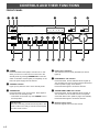
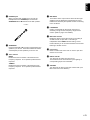
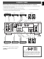
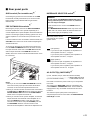
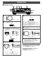
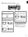
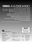
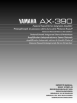
UCA
AX-596
STEREO AMPLIFIER
AMPLIFICATEUR STEREO
OWNER’S MANUAL
MODE D’EMPLOI I
• Explanation of Graphical Symbols
CAUTION
The lightning flash with arrowhead
symbol, within an equilateral triangle,
is intended to alert you to the
presence of uninsulated “dangerous
voltage” within the product’s
enclosure that may be of sufficient
magnitude to constitute a risk of
electric shock to persons.
RISK OF ELECTRIC SHOCK
DO NOT OPEN
CAUTION: TO REDUCE THE RISK OF
ELECTRIC SHOCK, DO NOT REMOVE
COVER (OR BACK). NO USER-SERVICEABLE
PARTS INSIDE. REFER SERVICING TO
QUALIFIED SERVICE PERSONNEL.
The exclamation point within an
equilateral triangle is intended to alert
you to the presence of important
operating and maintenance
(servicing) instructions in the
literature accompanying the
appliance.
IMPORTANT
Please record the serial number of this system in the
space below.
Model:
Serial No.:
WARNING
TO REDUCE THE RISK OF FIRE OR ELECTRIC
SHOCK, DO NOT EXPOSE THIS APPLIANCE TO RAIN
OR MOISTURE.
The serial number is located on the rear of the main
unit.
Retain this Owner’s Manual in a safe place for future
reference.
SAFETY INSTRUCTIONS
1
Read Instructions – All the safety and operating
instructions should be read before the unit is operated.
2
Retain Instructions – The safety and operating
instructions should be retained for future reference.
Power Sources – The unit should be connected to a
power supply only of the type described in the
operating instructions or as marked on the unit.
11
Power-Cord Protection – Power-supply cords should
be routed so that they are not likely to be walked on or
pinched by items placed upon or against them, paying
particular attention to cords at plugs, convenience
receptacles, and the point where they exit from the
unit.
12
Cleaning – The unit should be cleaned only as
recommended by the manufacturer.
13
Carts and Stands – The unit should be used only with
a cart or stand that is recommended by the
manufacturer.
Nonuse Periods – The power cord of the unit should be
unplugged from the outlet when left unused for a long
period of time.
14
A unit and cart combination should be
moved with care. Quick stops, excessive
force, and uneven surfaces may cause
the unit and cart combination to overturn.
Object and Liquid Entry – Care should be taken so that
objects do not fall into and liquids are not spilled into
the inside of the unit.
15
Damage Requiring Service – The unit should be
serviced by qualified service personnel when:
A. The power-supply cord or the plug has been
damaged; or
B. Objects have fallen, or liquid has been spilled into
the unit; or
C. The unit has been exposed to rain; or
D. The unit does not appear to operate normally or
exhibits a marked change in performance; or
E. The unit has been dropped, or the cabinet
damaged.
16
Servicing – The user should not attempt to service the
unit beyond those means described in the operating
instructions. All other servicing should be referred to
qualified service personnel.
17
Power Lines – An outdoor antenna should be located
away from power lines.
18
Grounding or Polarization – Precautions should be
taken so that the grounding or polarization is not
defeated.
3
Heed Warnings – All warnings on the unit and in the
operating instructions should be adhered to.
4
Follow Instructions – All operating and other
instructions should be followed.
5
Water and Moisture – The unit should not be used near
water – for example, near a bathtub, washbowl, kitchen
sink, laundry tub, in a wet basement, or near a
swimming pool, etc.
6
6A
7
Wall or Ceiling Mounting – The unit should be mounted
to a wall or ceiling only as recommended by the
manufacturer.
8
Ventilation – The unit should be situated so that its
location or position does not interfere with its proper
ventilation. For example, the unit should not be
situated on a bed, sofa, rug, or similar surface, that
may block the ventilation openings; or placed in a builtin installation, such as a bookcase or cabinet that may
impede the flow of air through the ventilation openings.
9
II
10
Heat – The unit should be situated away from heat
sources such as radiators, stoves, or other appliances
that produce heat.
FCC INFORMATION (for US customers only)
1.
2.
3.
IMPORTANT NOTICE : DO NOT MODIFY THIS
UNIT!
This product, when installed as indicated in the
instructions contained in this manual, meets FCC
requirements. Modifications not expressly approved
by Yamaha may void your authority, granted by the
FCC, to use the product.
IMPORTANT : When connecting this product to
accessories and/or another product use only high
quality shielded cables. Cable/s supplied with this
product MUST be used. Follow all installation
instructions. Failure to follow instructions could void
your FCC authorization to use this product in the
USA.
NOTE : This product has been tested and found to
comply with the requirements listed in FCC
Regulations, Part 15 for Class “B” digital devices.
Compliance with these requirements provides a
reasonable level of assurance that your use of this
product in a residential environment will not result in
harmful interference with other electronic devices.
Compliance with FCC regulations does not guarantee that
interference will not occur in all installations. If this
product is found to be the source of interference, which
can be determined by turning the unit “OFF” and “ON”,
please try to eliminate the problem by using one of the
following measures:
This equipment generates/uses radio frequencies
and, if not installed and used according to the
instructions found in the users manual, may cause
interference harmful to the operation of other
electronic devices.
The above statements apply ONLY to those products
distributed by Yamaha Corporation of America or its
subsidiaries.
Relocate either this product or the device that is being
affected by the interference.
Utilize power outlets that are on different branch (circuit
breaker or fuse) circuits or install AC line filter/s.
In the case of radio or TV interference, relocate/reorient
the antenna. If the antenna lead-in is 300 ohm ribbon
lead, change the lead-in to coaxial type cable.
If these corrective measures do not produce satisfactory
results, please contact the local retailer authorized to
distribute this type of product. If you can not locate the
appropriate retailer, please contact Yamaha Electronics
Corp., U.S.A. 6660 Orangethorpe Ave, Buena Park, CA
90620.
We Want You Listening For A Lifetime
YAMAHA and the Electronic Industries Association’s
Consumer Electronics Group want you to get the most out
of your equipment by playing it at a safe level. One that lets
the sound come through loud and clear without annoying
blaring or distortion – and, most importantly, without
affecting your sensitive hearing.
Since hearing damage from loud sounds is
often undetectable until it is too late, YAMAHA
and the Electronic Industries Association’s
Consumer Electronics Group recommend you
to avoid prolonged exposure from excessive
volume levels.
III
UNPACKING
DEBALLAGE
After unpacking, check that the following items are contained.
Après le déballage, vérifier que les pièces suivantes sont incluses.
STANDBY/ON
● Remote control
● Télécommande
DECK A/B
TAPE
DIR A
● Batteries (size AA, R6, UM-3)
● Piles (format AA, R6, UM-3)
DIR B
DISC SKIP
CD
–
PRESET
+
A/B/C/D/E
TUNER
MD
TAPE
CD/DVD
AUX
PHONO
TUNER
–
VOLUME
+
Opening and closing the front cover
Close the front cover whenever the controls inside the panel are not used.
Ouverture et fermeture du couvercle avant
Fermer le couvercle avant lorsque les commandes placées à l’intérieur du panneau ne sont pas utilisées.
To open the front cover
Pour ouvrir le couvercle avant
1
2
IV
To close the front cover
Pour fermer le couvercle avant
English
Thank you for selecting this YAMAHA stereo amplifier.
FEATURES
v 100W + 100W (8Ω) RMS Output Power, 0.015% THD, 20–20,000 Hz
v Highly Dynamic Power, Low Impedance Drive Capability
v Continuously Variable LOUDNESS Control
v CD/DVD DIRECT AMP Switch Used to Reproduce the Purest CD and DVD Sound
v PURE DIRECT Switch Used to Reproduce the Purest Source Sound
v REC OUT Selector Independent of Input Source Selection
v PRE OUT/MAIN IN Terminals for Connecting An Equalizer, Surround-Sound Processor, etc.
v Remote Control Capability
CONTENTS
SAFETY INSTRUCTIONS ....................................................................................... II
UNPACKING ........................................................................................................... IV
FEATURES ............................................................................................................... 1
CAUTION ...................................................................................................................2
NOTES ABOUT THE REMOTE CONTROL .............................................................. 3
CONTROLS AND THEIR FUNCTIONS .................................................................... 4
CONNECTIONS ........................................................................................................ 7
OPERATION ........................................................................................................... 10
TROUBLESHOOTING ............................................................................................ 13
SPECIFICATIONS ................................................................................................... 14
E-1
CAUTION: Read this before operating your unit.
1.
To assure the finest performance, please read this
manual carefully. Keep it in a safe place for future
reference.
13.
Do not connect any audio equipment to the AC outlet
on the rear panel if the equipment requires more power
than the outlet is rated to provide.
2.
Install this unit in a cool, dry, clean place – away from
windows, heat sources, sources of excessive vibration,
dust, moisture and cold. Avoid sources of humming
(transformers, motors). To prevent fire or electrical
shock, do not expose the unit to rain or water.
14.
3.
Never open the cabinet. If something drops into the
set, contact your dealer.
VOLTAGE SELECTOR
(China and General models only)
The voltage selector on the rear panel of this unit
must be set for your local main voltage BEFORE
plugging into the AC main supply.
Voltages are 110/120/220/240 V AC, 50/60 Hz.
4.
Do not use force on switches, controls or connection
wires. When moving the unit, first disconnect the
power plug and the wires connected to other
equipments. Never pull the wires themselves.
5.
The openings on the unit cover assure proper
ventilation of the unit. If these openings are
obstructed, the temperature inside the unit will rise
rapidly; therefore, avoid placing objects against these
openings. Install the unit in a well-ventilated area to
prevent fire or damage.
<Europe, U.K. and China models only>
Be sure to allow a space of at least 20 cm behind, 20
cm on both sides and 30 cm above the top panel of the
unit to prevent fire or damage.
6.
The voltage used must be the same as that specified
on this unit. Using this unit with a higher voltage than
specified is dangerous and may result in fire or other
accidents. YAMAHA will not be held responsible for
any damage resulting from use of this unit with a
voltage other than specified.
7.
Always set the VOLUME control to “∞” before starting
the audio source play. Increase the volume gradually
to an appropriate level after the play has been started.
8.
Do not attempt to clean the unit with chemical solvents
as this might damage the finish. Use a clean, dry
cloth.
9.
To prevent electric shock, match wide blade of plug to
wide slot and fully insert.
This Class B digital apparatus complies with Canadian
ICES-003.
WARNING
Do not change the IMPEDANCE SELECTOR switch
setting while the power to this unit is on, otherwise
this unit may be damaged.
If this unit fails to turn on when the POWER switch is
pressed:
The IMPEDANCE SELECTOR switch may not be set to
either end. If so, set the switch to either end when this
unit’s power supply is completely cut off.
(U.S.A. model)
Be sure to read the “TROUBLESHOOTING” section
regarding common operating errors before concluding
that the unit is faulty.
When not planning to use this unit for a long period
(ie., vacation, etc.), disconnect the AC power plug from
the wall outlet.
11.
To prevent lightning damage, disconnect the AC power
plug when there is an electric storm.
E-2
For Canadian Customers
SPEAKERS
10.
12.
When this unit is turned off by pressing the STANDBY/ON
switch on the front panel or the remote control, the
STANDBY indicator on the front panel lights up. This state
is called the standby mode. In this mode, this unit is
designed to consume a small amount of power. This
unit’s power supply is completely cut off from the AC line
only when the POWER switch on the front panel is set in
the OFF position or the AC power cord is disconnected.
Grounding or polarization – Precautions should be
taken so that the grounding or polarization of an
appliance is not defeated.
R
A
L
MAINS
AC OUTLETS
SWITCHED
I20V 60Hz
l00W MAX. TOTAL
CAUTION
R
L
SEE INSTRUCTION MANUAL FOR CORRECT SETTING.
IMPEDANCE SELECTOR
SET BEFORE POWER ON
B
A OR B : 4ΩMIN. /SPEAKER
A B : 8ΩMIN. /SPEAKER
A OR B : 6ΩMIN. /SPEAKER
A B : I2ΩMIN. /SPEAKER
IMPEDANCE SELECTOR
Battery installation
Remote control operation range
English
NOTES ABOUT THE REMOTE CONTROL
Since the remote control will be used for many of this unit’s
control operations, you should begin by installing the
supplied batteries.
1. Turn the remote control over and remove the battery
compartment cover by sliding it in the direction of the
arrow.
2. Insert the batteries (AA, R6, UM-3 type) according to the
polarity markings on the inside of the battery
compartment.
3. Close the battery compartment cover.
Remote control
sensor
1
Within approximately
6 m (19.7 feet)
3
2
Battery replacement
If you notice that the remote control must be used closer to
the main unit, the batteries are weak. Replace both
batteries with new ones.
Notes
● Use AA, R6, UM-3 batteries.
● Be sure the polarities are correct. (See the illustration
inside the battery compartment.)
● Remove the batteries if the remote control is not used for
an extended period of time.
● If batteries leak, dispose of them immediately. Avoid
touching the leaked material and contact with clothing,
etc. Clean the battery compartment thoroughly before
installing new batteries.
30°
30°
Notes
● The area between the remote control and the main unit
must be clear of large obstacles.
● Do not expose the remote control sensor to strong
lighting, in particular, an inverter type fluorescent lamp;
otherwise, the remote control may not work properly. If
necessary, position the main unit away from direct
lighting.
E-3
CONTROLS AND THEIR FUNCTIONS
FRONT PANEL
1 2 3
4
NATURAL SOUND
STEREO AMPLIFIER
5
6
AX–596
STANDBY
AUX
MD
TAPE
CD/DVD
TUNER
PHONO
PURE DIRECT
CD/DVD DIRECT AMP
POWER
ON
OFF
INPUT
VOLUME
l6
20
PHONES
SPEAKERS
A
BASS
l
B
0
l
2
STANDBY/ON
OFF
l
2
3
ON
TREBLE
3
4
4
5
0
l
2
l
2
3
3
4
5
BALANCE
4
5
5
0
REC OUT
FLAT
CD/DVD
l
l
2
2
3
3
4
4
L5
LOUDNESS
5 R
—30dB
I0
2
3
9
4
TAPE
MD
l2
28
8
60
2
TUNER
PHONO
AUX
4
40
8
5
6
7
0
–dB
7
1
2
3
8
9
0
A
POWER
Press this switch inward (ON) to use this unit. In this
state, you can turn on this unit or turn this unit in the
standby mode by pressing STANDBY/ON. Press this
switch to release it outward (OFF) to completely cut off
this unit’s power supply from the AC line.
4
5
STANDBY indicator
Lights up only while this unit is in the standby mode.
STANDBY/ON
Press this switch to turn on the power. Press again to
set this unit in the standby mode.
* This switch can be used only when POWER is set in
the ON position.
Standby mode
This unit is still using a small amount of power in this
mode in order to be ready to receive infrared-signals
from the remote control.
E-4
B
6
7
C D
E
F
Input source indicators
The indicator of the currently selected input source
lights up.
PURE DIRECT and indicator
Press this switch, and the indicator above it lights up.
You can listen to a source in the purest sound with this
function. (Refer to page 12 for details.)
Press this switch again to cancel this function.
CD/DVD DIRECT AMP and indicator
Press this switch, and the indicator above it lights up.
You can listen to a CD or DVD source in the purest
sound with this function. (Refer to page 12 for details.)
Press this switch again to cancel this function.
Remote control sensor
Receives signals from the remote control.
English
8
PHONES jack
When you listen with headphones, connect the
headphones to the PHONES jack and set both
SPEAKERS A and B switches to the OFF position.
A
PHONES
PHONES
B
C
9
0
SPEAKERS
Press the switch A or B (or both) inward (ON) for the
speakers you will use. Press and release the switch
outward (OFF) for the speakers you do not use.
Tone controls
BASS
Rotate this knob to increase or decrease the low
frequency response. The 0 position produces a flat
response.
TREBLE
Rotate this knob to increase or decrease the high
frequency response. The 0 position produces a flat
response.
D
E
F
BALANCE
The balance of the output volume to the left and right
speakers can be adjusted to compensate for sound
imbalances caused by the speaker location or listening
room conditions.
LOUDNESS
Used to compensate for the human ears’ loss of
sensitivity to high and low-frequency ranges at low
volume. (Refer to page 12 for details.)
REC OUT selector
Rotate this knob to select the source for recording to
an MD recorder or tape deck. This setting is
independent of the INPUT selector setting, so this
function allows you to record the selected source while
listening to another source.
Front cover
Refer to inside of the front cover on how to open and
close the front cover.
INPUT selector
Turn this knob to select the input source.
The selected source will be shown by the lighting of
corresponding input source indicator.
VOLUME
Turn this knob to raise or lower the volume level. (The
REC OUT level is not affected.)
E-5
REMOTE CONTROL
The remote control is designed to control the most commonly used functions of the main unit. If you have a YAMAHA CD
player, tuner, tape deck, etc. with remote control compatibility, this remote control will also control their various functions.
For Control of This Unit
1
STANDBY/ON
1
DECK A/B
STANDBY/ON
Press this key to turn on this unit or turn it into the
standby mode.
This key can be used only when the POWER switch on
the main unit is set in the ON position.
TAPE
Standby mode
In this state, this unit consumes a very small
quantity of power to receive infrared-signals from
the remote control.
1
DIR A
DIR B
DISC SKIP
2
CD
2
3
–
PRESET
+
A/B/C/D/E
Input selector keys
Press a key to select the input source.
VOLUME +/–
Press these keys to increase or decrease the volume.
3
TUNER
For Control of Other Components
2
3
MD
TAPE
CD/DVD
AUX
PHONO
TUNER
–
VOLUME
+
Note
The functions of the keys to control other YAMAHA
components are the same as the corresponding keys on
those components. Refer to those components’
instruction manuals for details.
1
2
3
E-6
Tape deck keys
These keys control tape decks.
* DIR A, B and A/B apply only to double cassette tape
decks.
* Pressing DIR A will reverse the tape direction on a
single cassette tape deck with the automatic reverse
function.
CD player keys
These keys control compact disc players.
* DISC SKIP is used for disc changers only.
Tuner keys
These keys control tuners.
PRESET +: Press this key to select the next preset
station number.
PRESET –: Press this key to select the previous
preset station number.
A/B/C/D/E: Press this key to select the group (A – E)
of preset station numbers.
English
CONNECTIONS
Caution: Plug in this unit and other components after all connections are completed.
● All connections must be correct, that is to say L (left) to L, R (right) to R, “+” to “+” and “–” to “–”. Also refer to the owner’s
manual for each of your components.
● Use RCA type pin plug cables for audio/video units except speakers.
● The output (or input) terminals of YAMAHA audio/video units numbered 1, 2, 3, 4, etc. on the rear panel must be
connected to the same-numbered terminals of this unit.
Turntable
Speakers A
LINE OUT
LINE IN
Tape deck, etc.
OUTPUT
GND
OUTPUT
Tuner
Right
Left
(U.S.A. model)
AUDIO SIGNAL
L
R
COUPLER
R
SPEAKERS
R
L
GND
PHONO
2
TUNER
PRE
OUT
3
IN
(PLAY)
MAIN
IN
L
R
*
1
CD/DVD
R
L
MAINS
AC OUTLETS
SWITCHED
I20V 60Hz
l00W MAX. TOTAL
TAPE
4
OUT
(REC)
3
IN
(PLAY)
CAUTION
R
*
MD
1
L
A
4
OUT
(REC)
SEE INSTRUCTION MANUAL FOR CORRECT SETTING.
IMPEDANCE SELECTOR
L
SET BEFORE POWER ON
2
B
A OR B : 4ΩMIN. /SPEAKER
A B : 8ΩMIN. /SPEAKER
A OR B : 6ΩMIN. /SPEAKER
A B : I2ΩMIN. /SPEAKER
AUX
3
CD player or
DVD player
1
2
3
****
,
,
,
Video cassette player,
etc.
To AC outlet
LINE IN
LINE OUT
AUDIO OUT
AUDIO OUT
* *
4
Right
Left
Speakers B
MD recorder, etc.
4
: Refer to page 9 for descriptions.
: Indicates the direction of signals.
PHONO
R
3
L
IN
(PLAY)
TAPE
4
OUT
(REC)
Note
These terminals are for connecting a turntable with an
MM or high output MC cartridge. If you have a turntable
with a low output MC cartridge, use an inline boosting
transformer or MC-head amplifier when connecting to
these terminals.
E-7
m Connecting speakers
Connect the SPEAKERS terminals to your speakers with
the wire with the proper gauge (keep it as short as
possible). If the connections are faulty, no sound will be
heard from the speakers. Make sure that the + and –
polarity markings of the speaker wires are observed and set
correctly. If these wires are reversed, the sound will be
unnatural and lack bass.
● One or two speaker systems can be connected to this
unit. If you use only one speaker system, connect it to
either the SPEAKERS A or B terminals.
● Use speakers with the specified impedance shown on the
rear of this unit.
Caution
Do not let the bare speaker wires touch each other or
any metal part of this unit. This could damage this unit
or the speakers, or both.
How to Connect:
SPEAKERS B terminals
SPEAKERS A terminals
Red: positive (+)
Black: negative (–)
Red: positive (+)
Black: negative (–)
1 Loosen the knob.
2 Insert the bare wire.
2
[Remove approx.
10 mm (3/8”)
insulation from the
speaker wires.]
3 Tighten the knob
and secure the wire.
1
2
1
3
3
1 Loosen the knob.
2 Insert the bare wire. [Remove approx.
10 mm (3/8”) insulation from the speaker wires.]
3 Tighten the knob and secure the wire.
<U.S.A., Canada, Australia, China and General
models only>
Banana Plug connections are also possible.
1
2
1 Tighten the terminal knob.
2 Simply insert the Banana Plug connector into the
terminal.
E-8
English
m Rear panel parts
GND terminal (For turntable use)
*
1
IMPEDANCE SELECTOR switch
Connecting the ground wire of the turntable to the GND
terminal will normally minimize hum, but in some cases
better results may be obtained with the ground wire
disconnected.
PRE OUT/MAIN IN terminals
*
To connect an external unit, first remove the jumper pins
from the PRE OUT/MAIN IN terminals, and then connect
the input terminals of that unit to the PRE OUT terminals
and its output terminals to the MAIN IN terminals. For
details, refer to the owner’s manual included with the unit to
be connected.
O SI
GNAL
R
L
TUNE
COUP
R
R
O
PRE
OUT
R
L
3
IN
(PLA
Y)
TAPE
1
4
OUT
(REC
)
3
IN
(PLA
4
OUT
(REC
)
If this unit fails to turn on when the POWER switch is
pressed:
The IMPEDANCE SELECTOR switch may not be set to
either end. If so, set the switch to either end when this
unit’s power supply is completely cut off.
Select the position whose
requirements your speaker
system meets.
IMPEDANCE SELECTOR
SET BEFORE POWER ON
A OR B : 4ΩMIN. /SPEAKER
A B : 8ΩMIN. /SPEAKER
(Left position)
If you use one pair of speakers, the impedance of
each speaker must be 4Ω or higher.
If you use two pairs of speakers, the impedance of
each speaker must be 8Ω or higher.
LER
L
R
MAIN
IN
4
Y)
CD/D
VD
L
AC OUTLET(S) (SWITCHED)
MD
R
A OR B : 6ΩMIN. /SPEAKER
A B : I2ΩMIN. /SPEAKER
(Right position)
If you use one pair of speakers, the impedance of
each speaker must be 6Ω or higher.
If you use two pairs of speakers, the impedance of
each speaker must be 12Ω or higher.
AUDI
2
PHON
WARNING
Do not change the IMPEDANCE SELECTOR switch
setting while the power to this unit is on, otherwise
this unit may be damaged.
2
Removing the jumper pins from the PRE OUT/MAIN IN
terminals enables this unit to operate separately as a
control amplifier and a power amplifier. These terminals are
used for connecting a signal-processing system such as a
graphic equalizer or a surround-sound processor to this
unit.
If such an external unit is connected to these terminals, the
VOLUME control of this unit can be used for adjusting the
overall sound level.
GND
*
3
R
L
AUX
B
Notes
● When you do not use the PRE OUT/MAIN IN terminals,
never remove the jumper pins from these terminals. If
removed, no sound will be outputted from this unit.
● When you use this unit with an external unit connected to
the PRE OUT and MAIN IN terminals, make sure that the
CD/DVD DIRECT AMP switch and the PURE DIRECT
switch on the front panel are turned off.
● When you use this unit as a power amplifier, connect the
output terminals of an external control amplifier etc. to
this unit’s MAIN IN terminals. In this case, this unit’s
controls will not function except the PHONES jack and
the SPEAKERS switches. Use the controls on the
external control amplifier to make volume adjustment etc.
*
(U.S.A., Canada, Europe, China and General models)
...................................................... 3 SWITCHED OUTLETS
(U.K. and Australia models) ............. 1 SWITCHED OUTLET
Use these to connect the power cords of your components
to this unit.
The power to the SWITCHED outlets is controlled by this
unit’s POWER or STANDBY/ON switch. These outlets will
supply power to any connected unit whenever this unit is
turned on.
The maximum power (total power consumption of
components) that can be connected to the SWITCHED AC
OUTLET(S) is 100W.
E-9
OPERATION
m Playing a source
5 8 4
STANDBY
2
3
STANDBY
AUX
8
MD
TAPE
CD/DVD
TUNER
PURE DIRECT
PHONO
CD/DVD DIRECT AMP
POWER
ON
OFF
INPUT
VOLUME
l6
20
SPEAKERS
PHONES
A
BASS
l
B
0
STANDBY/ON
3
4
OFF
l
2
3
ON
TREBLE
l
2
5
BALANCE
l
l
2
3
4
5
0
2
3
4
4
5
5
0
l
2
3
3
4
4
L5
LOUDNESS
l
2
5 R
FLAT
—30dB
I0
2
3
9
4
l2
REC OUT
TAPE
MD
CD/DVD
28
1, 7
4
8
TUNER
PHONO
AUX
4
40
8
5
6
7
2
60
0
–dB
1
5
l6
20
l2
28
8
Select speakers A or B.
SPEAKERS
4
40
A
2
60
Set to the “∞” position.
0
–dB
2
STANDBY
POWER
3
OFF
* Both speakers A and B can be selected.
* Be sure that the IMPEDANCE SELECTOR switch is
correctly set as explained on page 9.
* If you listen with headphones, press both switches to
release them outward (OFF).
Press POWER inward (ON).
ON
ON
B
OFF
6
If the STANDBY indicator is illuminated, press
STANDBY/ON to turn on the power. (The STANDBY
indicator turns off.)
Play the source.
7
l6
20
l2
STANDBY/ON
28
8
–
STANDBY/ON
–
VOLUME
+
4
40
+
–
+
2
60
0
–dB
Adjust the output level.
8
Turns off.
STANDBY
POWER
4
Adjust the tonal quality by using the BASS,
TREBLE, BALANCE, LOUDNESS controls, the
CD/DVD DIRECT AMP switch or the PURE
DIRECT switch. (Refer to page 12).
Select the desired input source.
–
MD
TAPE
CD/DVD
AUX
PHONO
TUNER
+
When you finish using this unit
Press STANDBY/ON again to set this unit in the standby
mode. (The STANDBY indicator lights up.)
To completely cut off this unit’s power
supply from the AC line
Press POWER to release it outward (OFF).
AUX
MD
TAPE
CD/DVD
TUNER
PHONO
The indicator of the selected source lights up.
E-10
English
m Recording a source to tape (or MD)
4, 6, 7
STANDBY
AUX
MD
TAPE
CD/DVD
TUNER
PHONO
PURE DIRECT
CD/DVD DIRECT AMP
POWER
ON
OFF
INPUT
VOLUME
l6
20
PHONES
SPEAKERS
A
BASS
l
B
0
2
STANDBY/ON
3
4
OFF
l
2
3
ON
TREBLE
l
4
5
5
0
BALANCE
l
2
l
2
3
3
4
4
5
5
0
l
2
2
3
3
4
4
L5
LOUDNESS
l
5 R
FLAT
—30dB
I0
2
3
9
4
l2
REC OUT
TAPE
MD
CD/DVD
28
8
TUNER
PHONO
AUX
4
40
8
5
6
7
2
60
0
–dB
2
1
2
Follow the steps 1–3 of “Playing a source” on page
10.
5
6
Select the source you want to record.
REC OUT
TAPE
CD/DVD
4
Begin recording on the tape deck (or MD recorder).
The sound of the recording can be monitored by
selecting the tape deck (or MD recorder) with the
INPUT selector.
TUNER
MD
PHONO
MD
TAPE
CD/DVD
AUX
PHONO
TUNER
AUX
–
3
4
+
Play the source.
7
Select the source with the INPUT selector and
adjust VOLUME to check the sound output.
–
MD
TAPE
CD/DVD
AUX
PHONO
TUNER
+
Listening to another source by selecting it with the
INPUT selector will not affect the recording.
Notes
● The VOLUME, BASS, TREBLE, BALANCE, LOUDNESS
controls, the CD/DVD DIRECT AMP switch and the
PURE DIRECT switch have no effect on the material
being recorded.
● Please check the copyright laws in your country to record
from records, compact discs, radio, etc. Recording of
copyright material may infringe on copyright laws.
l6
20
l2
28
8
–
VOLUME
+
4
40
–
+
2
60
0
–dB
E-11
m Sound control
Adjusting the BALANCE control
Adjusting the BASS and TREBLE controls
Adjust the balance of the output volume to the left and right
speakers to compensate for sound imbalance caused by
speaker location or listening room conditions.
BASS
l
0
2
l
0
3
4
4
5
5
0
l
2
2
3
3
4
4
5
5
l
2
2
3
3
4
BASS:
Turn this knob clockwise to increase (or counterclockwise to decrease) the low frequency
response.
4
L5
5 R
Using the CD/DVD DIRECT AMP switch
You can enjoy the purest possible sound from your CD or
DVD player by pressing this switch. The indicator above it
lights up. With this function on, input signals from the CD or
DVD player are sent directly to the built-in special amplifier
for CD/DVD bypassing the INPUT selector, the BASS,
TREBLE, BALANCE, LOUDNESS controls and the PRE
OUT/MAIN IN terminals, and then sent to the power
amplifier. This signal routing reproduces the purest sound
eliminating any alterations to the CD or DVD signals.
TREBLE: Turn this knob clockwise to increase (or counter
clockwise to decrease) the high frequency
response.
Adjusting the continuously variable
LOUDNESS control
This control compensates for the human ears’ loss of
sensitivity to high and low-frequency ranges at low volume.
This control is adjustable to retain full tonal range at any
volume level.
1
LOUDNESS
CD/DVD DIRECT AMP
FLAT
l
3
9
4
8
5
Using the PURE DIRECT switch
2
7
6
l6
20
l2
28
You can enjoy the purest possible sound from your audio
sources by pressing this switch. The indicator above this
switch lights up. With this function on, the audio signals
bypass the BASS, TREBLE, BALANCE, LOUDNESS
controls and the PRE OUT/MAIN IN terminals, thus
eliminating any alterations to the audio signals.
8
4
40
0
–dB
3
LOUDNESS
l
FLAT
—30dB
I0
3
9
4
Turn until the desired volume is
obtained.
8
5
Notes
● If both the CD/DVD DIRECT AMP and PURE DIRECT
switches are on, only the CD/DVD DIRECT AMP switch
will function.
● If this unit is turned off, sound may be distorted when
listening to a source with headphones that are connected
to an externally connected unit such as the CD player,
tape deck, etc.
● If any of the external units connected to this unit is turned
off, sound may be distorted when playing a source on
another unit that is also connected to this unit.
Set to the loudest listening level
that you would listen to.
2
60
2
PURE DIRECT
Set to the “FLAT” position.
—30dB
I0
2
E-12
l
2
3
BALANCE
TREBLE
l
6
7
WARNING
If the CD/DVD DIRECT AMP switch or PURE DIRECT
switch is pressed to turn it on with the LOUDNESS
control set at a certain level, the sound will suddenly
increase and may damage your ears or the speakers.
(The LOUDNESS control function may be bypassed.)
For this reason, be sure to press the CD/DVD DIRECT
AMP switch or PURE DIRECT switch after lowering the
volume or after checking that the LOUDNESS control is
properly set.
Refer to the chart below when this unit does not function properly. If the problem you are experiencing is not listed below or if
the instructions given below do not help, disconnect the power cord and contact your authorized YAMAHA dealer or service
center.
Problem
The unit cannot be turned on or
turns off suddenly soon after the
power is turned on.
This unit does not work normally.
No sound.
Cause
Power cord is not plugged in nor
completely inserted.
The IMPEDANCE SELECTOR switch on
the rear panel is not set to either end.
There is an influence of strong external
noise (lightning, excessive static
electricity, etc.) or a misoperation on this
unit while using this unit.
Incorrect output cord connections.
Appropriate input source is not selected.
The sound suddenly goes off.
Only one of the speakers
produces the sound.
There is a lack of bass and no
ambience.
Sound “hums”.
The volume level is low while
playing a record.
The volume level cannot be
increased, or sound is distorted.
The sound is degraded when
listening with the headphones
connected to the compact disc
player or tape deck that are
connected with this unit.
Sound level is low.
The input source cannot be
changed, though the INPUT
selector is turned.
Using the BASS, TREBLE,
BALANCE and LOUDNESS
controls does not affect the tone.
The remote control does not
work.
The remote control does not
function properly.
The SPEAKERS switches are not set
properly.
Speaker connections are not secure.
The protection circuit has been activated
because of short circuit etc.
Incorrect setting of the BALANCE
control.
Incorrect cord connections.
The + and – wires are connected in
reverse at the amplifier or speakers.
Incorrect cord connections.
No connection from the turntable to the
GND terminal.
The record is being played on a
turntable with an MC cartridge.
The component connected to the TAPE
OUT or MD OUT terminals of this unit is
turned off.
This unit is turned off or in the standby
mode.
The LOUDNESS control is functioning.
The CD/DVD DIRECT AMP switch is
ON.
The CD/DVD DIRECT AMP switch or
PURE DIRECT switch is ON.
The batteries of this remote control are
weak.
Wrong distance or angle.
Direct sunlight or lighting (of an inverter
type fluorescent lamp etc.) is striking the
remote control sensor of the main unit.
English
TROUBLESHOOTING
What to Do
Firmly plug in the power cord.
Set the switch to either end when this
unit is off.
Turn off this unit by pressing the
POWER switch. After about 30 seconds
have passed, turn on this unit and
operate this unit again.
Connect the cords properly. If the
problem persists, the cords may be
defective.
Select an appropriate input source with
the INPUT selector.
Set the corresponding SPEAKERS
switch to the ON position.
Secure the connections.
Turn off this unit by pressing the
POWER switch, and then turn this unit
on to reset the protection circuit.
Adjust it to the appropriate position.
Connect the cords properly. If the
problem persists, the cords may be
defective.
Connect the speaker wires in the
correct phase (+ and –).
Firmly connect the audio plugs. If the
problem persists, the cords may be
defective.
Make the GND connection between the
turntable and this unit.
The turntable should be connected to
this unit through the MC head amplifier.
Turn on the power to the component.
Turn on the power to this unit.
Set the LOUDNESS control to the FLAT
position.
Switch off the CD/DVD DIRECT AMP
switch.
The CD/DVD DIRECT AMP switch or
PURE DIRECT switch must be
switched OFF to use those controls.
Replace the batteries with new ones.
The remote control will function from a
maximum range of 6 meters and no
more than 30 degrees off-axis from the
front panel.
Reposition of the main unit.
E-13
SPECIFICATIONS
Power Section
Control Section
Minimum RMS Output Power
8Ω, 20 Hz to 20 kHz, 0.015% THD ................ 100W+100W
Input Sensitivity/Impedance
CD/DVD, etc. ............................................... 150 mV/47 kΩ
PHONO (MM) ............................................... 2.5 mV/47 kΩ
Maximum Output Power (EIAJ)
(1 kHz, 10% THD)
8/6Ω ........................................................................ 145/170W
Output Level
PRE OUT ............................................................ 1V/1.2 kΩ
REC OUT ................................................... 150 mV/0.6 kΩ
Dynamic Power (IHF)
8/6/4/2Ω ............................................... 140/170/220/290W
Headphone Output ............................................. 0.33V/680Ω
DIN Standard Output Power
(4Ω, 1 kHz, 0.7% THD) ................................................ 155W
Channel Separation (1 kHz/10 kHz)
CD/DVD (Input 5.1 kΩ Terminated) ................ 65 dB/50 dB
IEC Output Power (8Ω, 1 kHz, 0.015% THD) .............. 110W
Tone Control Characteristics
BASS ........................................................ 510 dB (20 Hz)
TREBLE .................................................. 510 dB (20 kHz)
Power Band Width
8Ω, 50W, 0.03% THD ............................... 10 Hz to 50 kHz
Damping Factor
8Ω, 20 Hz to 20 kHz ..................................................... 320
Frequency Response .................... 20 Hz to 20 kHz50.5 dB
20 Hz to 100 kHz +0.5, –3 dB
Total Harmonic Distortion (20 Hz to 20 kHz)
CD/DVD to SP OUT (8Ω, 50W) .............................. 0.008%
Signal-to-Noise Ratio (IHF-A Network)
CD/DVD (Input Shorted, CD/DVD DIRECT AMP: ON)
............................................................................... 110 dB
PHONO (MM)
(Input Shorted) ........................................................ 92 dB
Residual Noise (IHF-A Network)
CD/DVD DIRECT AMP: ON ..................................... 35 µV
Continuous LOUDNESS Control
Attenuation ................................................ –30 dB (1 kHz)
General
Power Supply
[U.S.A. and Canada models] .................... AC 120V, 60 Hz
[Europe and U.K. models] ......................... AC 230V, 50 Hz
[Australia model] ....................................... AC 240V, 50 Hz
[China and General models]
........................................ AC 110/120/220/240V, 60/50 Hz
Power Consumption ...................................... Approx. 220W
AC Outlets
3 SWITCHED OUTLETS
[U.S.A., Canada, Europe, China and General models]
............................................................... 100W max. total
1 SWITCHED OUTLET
[U.K. and Australia models] .................... 100W max. total
Dimensions (W x H x D) ....................... 435 x 151 x 396 mm
(17-1/8” x 5-15/16” x 15-9/16”)
Weight ................................................ 10.6 kg (23 lbs. 5 oz.)
Accessories .................................................. Remote control
Batteries
Specifications subject to change without notice.
E-14
YAMAHA
YAMAHA
YAMAHA
YAMAHA
YAMAHA
YAMAHA
YAMAHA
ELECTRONICS CORPORATION, USA 6660 ORANGETHORPE AVE., BUENA PARK, CALIF. 90620, U.S.A.
CANADA MUSIC LTD. 135 MILNER AVE., SCARBOROUGH, ONTARIO M1S 3R1, CANADA
ELECTRONIK EUROPA G.m.b.H. SIEMENSSTR, 22-34, 25462 RELLINGEN, BEI HAMBURG, F.R. OF GERMANY
ELECTRONIQUE FRANCE S.A. RUE AMBROISE CROIZAT BP70 CROISSY-BEAUBOURG 77312 MARNE-LA-VALLEE CEDEX02, FRANCE
ELECTRONICS (UK) LTD. YAMAHA HOUSE, 200 RICKMANSWORTH ROAD WATFORD, HERTS WD1 7JS, ENGLAND
SCANDINAVIA A.B. J A WETTERGRENS GATA 1, BOX 30053, 400 43 VASTRA FRÖLUNDA, SWEDEN
MUSIC AUSTRALIA PTY, LTD. 17-33 MARKET ST., SOUTH MELBOURNE, 3205 VIC., AUSTRALIA
Printed in Malaysia
1
V576270-1
-