1
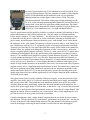
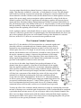
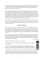
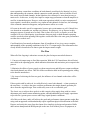
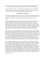
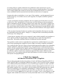
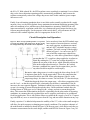
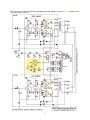
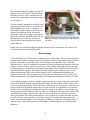
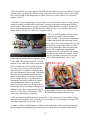
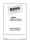
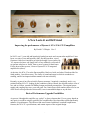
A New Look At an Old Friend
Improving the performance of Dynaco’s SCA-35 & ST-35 amplifiers
By David C. Gillespie
Rev.2
In 1965 I was 13 years old and hopelessly hooked on music and vacuum tube amplifiers. I have
been, ever since I saw and heard my dad’s first hifi purchase, a used
Grommes Little Jewel amplifier (at right) he bought 8 years earlier. By
’65, anyone who knew our family knew of my addiction, so friends of
my parents asked me to “build” them a stereo system for their home.
For the heart of that system, I chose a Dynaco SCA-35 integrated
amplifier kit (above).
At the time, the SCA-35 was the finest amplifier I had ever built, and when I first heard the finished product, I was blown away. The clarity of sound and range to which it extended was
startling, and left an impression that remains with me to this day.
Recently, as part of an effort to build a Dynaco museum, I acquired a completely stock, very
pristine-looking SCA-35. Judging by the condition of the pc boards, the unit did not have a lot of
use, and as a bonus, sported real Mullard output and phono preamp tubes. The original power
supply and coupling caps were even still good. For a unit whose serial number shows it to be one
of the first few kits produced of this model, it was in remarkable shape to say the least.
Basis of Performance Upgrade Possibilities
As great as I thought this amplifier was, today I’ve always known that if I ever got my hands on
one again, it would be uniquely qualified for a modification I developed that could significantly
enhance it’s performance. The effort to find out all started with those wonderful output transformers, the SCA-35’s specifications, and certain aspects of the original design.
1
In classic Dynaco fashion, the Z-565 transformers (at left) used in the SCA35 are excellent performers. The best examples are capable of delivering the
full 20-20 kHz bandwidth at full rated power with very low distortion,
although on the low end, the figure is often closer to 22 Hz. They also
provide an optimized Ultra-Linear output stage configuration that gives the
SCA-35 a clear advantage in damping and regulation of power delivered to a
speaker load, versus that of an equivalent pentode output stage. The output
transformers always determine the ultimate capability of a given design, and
in the SCA-35, the transformers set a very high benchmark indeed.
Now the specifications for this amplifier would have you believe that the full capability of these
output transformers are fully utilized, and they are – but only under very limited conditions.
Power output is stated as “35 watts continuous” – but offers no clue as to what frequency range
or distortion level this power is achieved at. In fact, when those elements are included in the
power ratings, the information is then provided only on an “each channel” basis. On the bench,
the ambiguity of the “each channel” designation is shown for what it really is: each channel at a
time. Measured as such, the SCA-35 is generally capable of meeting its performance standards.
That may have been fine for early stereo that often threw nearly all the sound to one channel for
dramatic effect, but with the more balanced presentation of today’s stereo sources, full performance is required in both channels at all times. The fact is, when a stock SCA-35 is tested under
conditions of both channels driven, the specifications suffer significantly such that it becomes
about a 27-28 watt RMS (total) amplifier, at greatly elevated distortion (typically 3-5 times that
of single channel performance). To be very clear here, that means that when both channels are
driven, the power output of each channel drops to about 80% of single channel performance, and
at that reduced power, distortion is 3-5 times higher than what is produced at the higher power
output of single channel operation. In an amplifier where every watt counts with today’s dynamic
program sources, this is a significant drop in performance in deed. The bottom line is, under realistic stereo conditions where both channels are operating, the low distortion capabilities of the
output transformers in the SCA-35 are not used effectively, because the operating point of the
output stages themselves have shifted significantly to one of higher distortion under conditions
of elevated power output.
The typical cause of this lies in the capability of the power supply, versus the total needs of the
amplifier. Specifically, the SCA-35 uses an economical solid-state power supply, and amplifiers
that operate in class AB1. This means that as the amplifiers produce more power, the current
drawn by them increases significantly. Against the increased demand from the amplifiers, the
output of the power supply drops. Of concern here, is that the B+ “sag” created by this increased
current draw is much greater when both channels are driven, versus that of a single channel. This
happens in virtually all stereo amplifiers, but a closer look at what is really happening here will
give the first clue as to how greater performance can be had.
Consider what happens when a single channel is measured on the test bench for power output
and distortion. The specifications for “each channel” performance are typically met – but not just
because of the merits of the channel being measured. The idle channel is also playing a significant roll in helping to achieving the driven channel’s results. But how does that happen?
2
As power output from the driven channel increases, it draws more current from the power
supply. This drops the available B+ somewhat – to both channels of course. The idle channel
reacts to this by reducing it’s quiescent current draw, making more current available for the
driven channel to consume. In other words, the idle channel acts as a shunt regulator across the
output of the power supply, acting to maintain a rather consistent B+ voltage for the driven
channel to operate from. This has a significant roll in helping to produce the increased power
output and lower distortion readings obtained when each channel is measured individually. In
fact, all else being equal, if one channel of the SCA-35 was powered by it’s own power supply of
half the capability as that in the complete amplifier, it would not deliver the same performance
simply because the regulating effect of the B+ is gone!
So B+ regulation, and how each channel affects it is surely in play here: when only one channel
is driven, it effectively operates from a regulated supply, but when both channels are driven, not
only is the regulation effect gone, now each channel is acting to the detriment of each other.
However, in the SCA-35, there are even more devious gremlins at work.
That Common Cathode Connection
In the SCA-35, the cathodes of all four output tubes are connected together and
draw their collective current through one common cathode resistor, which is
bypassed by one common bypass capacitor (at right). It is likely the most discussed aspect of the SCA-35’s design. It was also surely an economic move,
and one which whether to stave off criticism, or herald its virtues, Dynaco felt
the need to comment on, stating it “improves the performance of the output
stage”. From the standpoint of stereo operation, it does somewhat due to the
unique signals being presented to each channel. But to understand why, again
goes back to the amplifier’s behavior on the test bench.
At issue here is the rather large disparity between the performance of one
channel when driven separately, versus that of both channels driven together.
Since the amplifiers employ cathode bias, its automatic adjustment capability
allows the bias to adjust itself to the prevailing conditions offered. That means
that as B+ sags under increased power output, maximum available power output
will drop, but a component of the cathode bias action will also react to help
maintain a low distortion operating point for the new conditions offered ––
except, that’s not what’s happening here. In the SCA-35, when both channels
are driven versus just one, available power output per channel drops about 20%
as expected, but distortion increases 3-5 times! What’s going on? The answer
lies in two important decisions Dynaco made: the use of a common cathode
connection between all four tubes, and the use of cathode bias to begin with.
To many, the effect of the common cathode connection is simply an economy that creates the
nuisance of having to use a matched quad of output tubes. It does, but that should be considered
a goal rather than a nuisance anyway if you are trying to achieve truly identical channels. But
there is an even bigger element at play with the common connection than simply requiring a
matched quad of tubes. Once again, a closer look at what is really happening here will give the
second clue as to how greater performance can be had.
3
Earlier, it was shown that when a single channel was driven and measured, the idle channel actually helped contribute to the excellent performance produced by the driven channel, because it
was actively working to help regulate the B+ supply. The common cathode connection has a
huge part in the effectiveness of this action.
Again, consider what happens on the test bench when a single channel is driven to full power.
The average current draw of the stage has increased, meaning that the bias across the cathode
resistor will increase also. However, because of the common cathode connection, the increased
bias created by the driven channel also works to reduce current flow in the idle channel, which
now amplifies its effectiveness to function as a B+ regulator. But most importantly, it can also be
seen that this process is ultimately working to effectively regulate the bias itself, since increased
current draw in one channel causes reduced current draw in the other. The end result is that now
the driven channel is actually operating under conditions of fixed bias!
On the other hand, when both channels are driven, they both pull increased current across the
cathode resistor. In that condition, the bias cancellation effects previously noted vanish, and conditions revert to that of traditional cathode bias operation, with elevated bias voltage across the
common cathode resistor.
Tying It All Together
Now it can be seen why there is such a significant performance discrepancy between a single,
and both channels driven condition in the SCA-35. Between these two conditions, the unit automatically transforms itself from optimum conditions of fixed bias operation from a regulated
power supply when a single channel is driven, to much less than optimum conditions of cathode
bias operation from a non-regulated power supply of much smaller capacity when both channels
are driven.
Obviously, some of the power loss in each channel is due to power supply sag when both channels are producing power. But much of it is also due to the increased drop across the cathode
resistor as well. However, the notable rise in distortion between the two conditions is entirely due
to the huge shift in output stage operating conditions created by the increased bias generated
when both channels are operating.
Russian EL84M
From the preceding then, the following facts can be drawn:
1. The Z-565 transformer is optimally matched to 6BQ5 tubes when they are operated
with fixed bias.
2. The Z-565 represents too low of a load (numerically) for 6BQ5s operated with
cathode bias. Use of cathode bias with this transformer results in excessive shifting of
the operating point, resulting in reduced absolute power output and increased distortion.
In designing the SCA-35, Dynaco was clearly aware of these facts. But in using a common
cathode connection, resistor, and bypass capacitor for both channels, they cleverly achieved
economy, simplicity, and for stereo operation, a dynamic form of operation that lies somewhere
in between cathode and fixed bias operation – all at the same time. It was assumed that with
4
stereo operation, current draw conditions in both channels would rarely be identical, so given
that understanding, the common cathode connection would generally work to hold the overall
bias steady between both channels. In that light then, the connection is more than just an economic move. In this case, it really does improve output stage performance when the amplifier is
used for its intended purpose. However, with mono operation (which is a major component of
stereo signals), current draw would be very similar in both channels. In that case, the advantage
of the common connection disappears, and performance suffers as a result.
Of course in the end it was all a compromise, because price point matters as well. Cathode bias
was deemed an acceptable one, and the rest is history. In retrospect, it is so Dynaco in their
attempt to squeeze so much out of so little. That it came off so well is so Dynaco as well. But
wouldn’t it be nice if the disparity in performance between single or both channels operating
could be resolved so that operating both together would still achieve the same great performance
as either does on their own?
Careful analysis of measured performance from all conditions of use gives a more complete
understanding of the operating conditions in the SCA-35’s output stages. That information also
clearly defines what needs to be done to gain the improvements sought.
The Plan
When all of the forgoing is taken into account, the plan for improvement boils down to:
1. Convert each output stage to fixed bias operation. With the Z-565 transformer, this will minimize shifts in the operating point, which minimizes distortion and maximizes power output in the
process.
2. Minimize the effects of power supply sag between quiescent and full power output conditions
when both channels are driven. This also works to minimize shifts in the operating point, adding
to the benefits noted above.
3. By virtue of achieving the first two goals, the influence of one channel on the other will be
eliminated.
If these goals could be achieved, it would effectively cause both channels -- when operating at
the same time -- to achieve the same excellent performance that single channel operation produces from the original design. That would surely seem to be a worthwhile goal.
The classic way to achieve these goals is to add a negative bias supply along with its various
adjustment pots, install current monitoring points, and add additional power supply capacitance
to provide for a greater power reserve under large signal dynamic conditions.
All of this can be done, and it will achieve the goals and performance improvements sought. But
using such an approach would undoubtedly require significant physical modification to the little
Dynaco, and surely take away from the charm of its simplicity in design and operation. Hafler
and Laurent championed the KISS principle to the max in all of their pieces of equipment, so
5
deviating from that approach really takes away from what the original designers intended it to
be: a clean looking, simple, but high performing integrated amplifier of minimalist design.
So what alternatives do we have? Is there a different approach that could achieve all the goals
outlined, while still maintaining that wonderful KISS principle that Dynaco capitalized on so
well? It turns out there is, but it’s probably not what you might be thinking.
A Somewhat New Approach
Since the idea of adding a new bias supply for fixed bias operation has been eliminated, but bias
is obviously still needed, then all we have left is to work with is the original bias scheme of providing bias via the cathodes. But given what we know now, it must be fixed, or at least,
regulated.
The idea of regulating the cathode bias of a cathode bias amplifier is not particularly new. This
has been accomplished before with Zeners strapped across the cathode resistor to limit any
upward excursions in bias voltage. Others have used just the Zeners themselves, while still
others have lit the room up with a series string of LEDs in the cathode circuit to achieve bias stability and light at the same time. All of these approaches have limitations, not the least of which
with the last two is that the bias does become fixed alright – but fixed to the point that it will not
change regardless of what other conditions may change in the amplifier. Unless all the other
voltage sources are regulated in the amplifier as well, this is not necessarily a good thing.
Classic power supplies for traditional fixed bias amplifier designs typically provide unregulated
sources of B+ and negative bias from a common power transformer. Think of the Dynaco MK II,
III, and Stereo 70 designs for example. This works very well, as then both sources tend to rise or
fall as the prevailing conditions dictate: if the AC line goes up, so does the B+ and the bias. If the
AC line goes down, the opposite happens. It also happens to a smaller degree as the load on the
power supply itself changes due to changing needs in power output. This too tends to cause both
sources to rise and fall together. The bottom line here, is that with this approach, the ratio
between the B+ and bias voltages always remain relatively constant. This keeps the output tubes
out of trouble under quiescent conditions, and minimizes distortion under dynamic conditions.
On the other hand, regulating just the B+ or just the bias supply will usually lead to big problems. If either one of them is regulated, while the other is not, it allows the relative magnitudes
of the two sources to wander either way from optimum – and trouble exists either way it chooses
to go. If it wanders so that too little quiescent current is drawn in the output stage, distortion
increases rapidly. If it wanders the other direction, dissipation levels can be exceeded in the
output stage and lead to short output tube life. This is why either both of these sources need to be
regulated, or neither of them. Just regulating one is asking for trouble. That’s also why the idea
of using just Zeners or LEDs to establish and regulate cathode bias is not a very effective or safe
solution for output stage biasing. Strapping Zeners across the existing bias resistor in the SCA-35
might help somewhat, but Zeners can be imprecise in lower voltage values, are not easily adjustable without additional circuitry, and could still put the output tubes in potential danger with a
rising AC line voltage.
6
So existing efforts to regulate cathode bias are problematic at best or destructive at worst,
because the problems they solve are done so at the expense of introducing others. The problems
of the existing cathode bias system have already been established for the SCA-35, and conversion to traditional fixed bias operation has been ruled out on the basis of complexity.
It appears that what is needed then, is a new type of bias regulator – one that apparently has not
been developed yet. In an effort to devise such a regulator, it is helpful to define the qualities
required of it:
1. From a performance and safety standpoint, this new regulator must fix the bias at a set level,
yet allow it to “float” around that level as necessary, in such a fashion as to always maintain a
proper relationship with other operating voltages in the output stage. This quality is highly desirable, as it creates a condition where both the B+ and bias sources are effectively regulated, since
they would remain relatively linked to one another. This requirement also means that the regulating element will need to be an active device, connected in series fashion to effect proper control.
2. The set point of operation for this new regulator must be adjustable, allowing ease in setting
the relationship between bias and B+ voltages (i.e., setting the bias) for maximum performance
as tubes age, or are changed out.
3. Since this new regulator will be series connected, it must exhibit essentially zero impedance to
all AC and DC currents flowing through it, allowing the bias to remain fixed regardless of
current flow. This quality establishes the basis of traditional fixed bias operation.
These qualities would result in an adjustable bias regulator that would hold the bias very steady
at the chosen operating point, regardless of power output, to maximize amplifier performance.
Yet it would also allow the bias to float as required, and automatically maintain a set relationship
with the available B+ under any conditions of use. This performance would represent the best
qualities of both regulated bias/B+ supplies, and fixed bias operation, and is exactly the kind of
bias regulator we need to fix the ills of the SCA-35’s existing cathode bias system. A bias regulator with these qualities would create a brand new approach to bias control, unlike any other
known to exist. Can a regulator with this kind of performance be built in a simple way that maintains Dynaco’s design philosophy?
A Really New Approach:
An Enhanced Fixed Bias (EFB™) Regulator
The preceding paragraph describes the qualities of what I call Enhanced Fixed Bias (EFB™). It
can be applied in place of a traditional cathode bias resistor by way of an EFB cathode regulator,
or in a traditional fixed bias installation by way of an EFB supply regulator. In either case, EFB
can be achieved very easily from a common three-terminal voltage regulator. In the SCA-35, an
EFB cathode regulator does a very effective job of providing fixed bias operation at the cathode,
while also maintaining a set relationship with differing B+ voltages produced under various
forms of operation. EFB is so effective in fact, that with a sag in B+ due to the application of
power, bias is actually reduced for the output tubes accordingly! This is exactly opposite of what
happens with a cathode bias resistor, but is exactly and ideally what we want to have happen in
7
the SCA-35: With reduced B+, the EFB regulator reacts accordingly to maintain it’s set relationship, so the lowest distortion operating point is automatically maintained. And, because the
regulator automatically reduces the voltage drop across itself in this condition, power output
increases as well.
Finally, from a distortion standpoint, there is now little need to actually regulate the B+ supply
anymore. Once set, the EFB regulator always maintains the minimum distortion operating point
under all conditions of use, whether one or both channels are operating. With EFB, the only
improvement that B+ regulation would offer, is to eliminate any power output loss due to sag
from an unregulated supply. For the purposes of this article then, I will concentrate on EFB
achieved with a cathode regulator, since it is appropriate for the SCA-35.
Circuit Description And Operation
In its most basic form, the EFB cathode regulator consists of no more than two resistors,
one small capacitor, an adjustment control,
and an LM337 adjustable negative voltage
regulator. The basic concept of the design is
shown in Figure-1. As can be seen, the 337
acts to hold the output stage cathode bias
steady, at a value above ground that is slightly
greater than the 337’s own bias voltage applied to its adjust terminal. By making the 337’s own bias voltage adjustable, it
adjusts the set point of this device, which ultimately adjusts the
bias on the output tubes themselves. Therefore, this control
becomes a standard bias control for the output tubes, just like
any other fixed bias amplifier would employ.
Figure-1. Basic concept of EFB operation. 337 operates
as a unity gain buffer, with output set by B+. By varying
the voltage divider tap, the bias/B+ ratio is adjustable.
But notice what voltage source is used to supply the bias voltage for the 337.
It originates from the B+ for the output tubes. This is the connection that
turns normal fixed bias into EFB. Notice what happens if the B+ to the
output stage drops, for whatever reason. The bias to the 337 then also drops,
which then drops the bias to the output stage – all in direct proportion to the
new B+ level – so that the original bias/B+ relationship for the tubes is maintained. If the B+
increases, the exact opposite happens. Traditional cathode bias reacts in a somewhat similar way,
except it is reacting to current flowing through the tubes. Unlike traditional cathode bias, the
floating feature of EFB reacts only to changes in B+ voltage, and not to current through the
tubes. This means that EFB maintains the bias/B+ relationship for the tubes under all operating
conditions, in a manner that only regulated bias and B+ supplies could achieve in a traditional
fixed bias application. This is why further efforts to regulate the B+ supply of an SCA-35 operating with EFB only serve to restore lost power from B+ sag, and not reduce distortion in any way.
Finally, capacitor C is added to help ensure the stability of the 337, with a value small enough to
still allow for quick response to changing power supply conditions. The complete schematic of
the modification as installed is shown in Figure-2 (on the next page), while before and after performance measurements for the stock design, and that with EFB are shown in Figure-3 on p.10.
8
Figure-2. Complete schematic of the SCA-35 modified with EFB. Additions are shown in yellow. Cathode resistor
to be removed is circled in red.
9
Figure-3. The table readily shows the drop in performance of the original design when both channels are driven,
versus performance when EFB is used. In most cases, EFB performance with both channels driven is better than
single channel performance of the original design.
Single Channel Driven
Before
Freq
Max Power (W)1 Distortion (%) 2
20Hz
17.0
1.60
25
17.0
0.90
1K
18.0
0.17
20K
17.2
0.65
IM Distortion 3
0.80
After
Max Power (W)1
18.9
18.9
18.9
18.5
Change (%)
+11.2
+11.2
+5.0
+7.6
Distortion (%) 2 Change (%)
1.60
0
0.75
-17
0.12
-29
0.52
-20
0.40
-50
After
Max Power (W)1
17.6 X2
17.6 X2
17.6 X2
17.2 X2
Change (%)
+29.4
+29.4
+20.5
+29.3
Distortion (%) 2 Change (%)
1.70
-15
0.80
-43
0.18
-81
0.57
-78
0.75 6
-62
Both Channels Driven
Before
Freq
Max Power (W)1 Distortion (%) 2
20Hz
13.6 X2
2.00
25
13.6 X2
1.40
1K
14.6 X2
0.95
20K
13.3 X2
2.6 4
IM Distortion 3
2.00 5
Notes
Ÿ Original specs are: THD 1.0% or less, from 20 - 20 kHz, within 1 dB of 17.5 watts, (each channel).
IM 1.0% or less at 17.5 watts (each channel). 0.2% or less on any input at average listening levels.
Ÿ These represent average, but realistic figures – some tubes favored power or distortion at one frequency, other tubes at
others. All power is RMS.
Ÿ (1) Max Power is measured at the onset of visual clipping.
Ÿ (2) Total harmonic distortion is measured at 13.65W, which is 1dB below rated power.
Ÿ (3) Intermodulation distortion is measured with 60 Hz and 7 kHz, mixed 4:1, at 17.5W equivalent for each channel.
Ÿ (4) Unable to produce 13.65W for measurement. Distortion is at max power.
Ÿ (5) Unable to produce 17.5W equivalent for measurement. Distortion is at max equivalent power of 14.65W.
Ÿ (6) Note that this IM test is at the specified 17.5W equivalent power – an increase of 19% over the test before the mod.
Cathode Voltage Change at Max Power
Single Channel
Both Channels
Before
14.05 to 15.27
14.05 to 17.85
(From zero to maximum power output at 1kHz.)
After
14.65 to 14.03
14.65 to 13.39
New Output Stage Operating Conditions
The development of the EFB circuit provides new artillery in the arsenal of weapons to achieve
really great amplifier performance economically. The cathode regulator provides exacting, fixed
bias operation at the cathodes, and solves the problems attributed to the original cathode bias
installation in the SCA-35. But not to be over-shadowed is one other very important change that
results from the SCA-35’s conversion to fixed bias.
The original cathode bias resistor’s value was chosen as a huge compromise: one that would not
let the operating point fall completely off a cliff with the application of full power (to both
channels in this case), but one that would also keep output tube dissipation within limits under
quiescent conditions. In the end, a value was chosen that kept the tubes safe (but pushed them
right to their limits), and then delivered whatever performance it could under full power
10
conditions in both channels. We have seen what that compromise produced: under-biased tubes
at quiescent conditions which shortened their life, and over-biased tubes at full power conditions
in both channels, leading to excessive distortion and power loss. This situation required the
output tubes to draw about 35 mA each under quiescent conditions, and resulted in nearly 12
watts of dissipation for each tube. This also gave the SCA-35 a well deserved reputation for
eating up output tubes.
Converting the output stage to EFB now eliminates those compromises. It allows maximum
power and minimum distortion under all conditions of use. As an added bonus, with the Z-565
transformer operated under conditions of fixed bias, the 6BQ5 output tubes now produce the
lowest distortion with a quiescent current of only 27 mA per tube! Now, not only are the output
stages operating with much lower distortion and greater power output when both channels are
driven, they are also doing so with at least 20% less dissipation under quiescent conditions. The
effect this has on tube and component life is enormous. All things considered then, the original
cathode bias system in the SCA-35 is simply no match for the performance enhancements that
EFB brings to this amplifier.
Installation
Installation of the EFB cathode regulator is a
relatively easy operation in the SCA-35, as the
circuit associated with it is so simple. In my
unit, all of the basic components for the regulator itself have been wired point-to-point inside
the back panel — in the area between the output
terminal strips and RCA jacks, as seen in Figure-4 and Figure-5. This required the
installation of one dual lug terminal strip,
mounted to one of the screws for the RCA
Figure-4. No drilling needed: The bias pot goes in an
jacks, while the 337 is mounted to a screw
existing hole, originally intended for an optional headsecuring the top output terminal strip.
phone jack.
The 337’s mount tab is internally connected to
it’s input terminal, which in this application is
connected to chassis ground. However, an isolation mounting kit should still be used to
prevent the possibility of ground loops being
formed. The heat sinking so provided is more
than adequate, as the 337 dissipates less than
2.5 watts under worst case conditions. For
ease of construction, before installation, I
snipped the leads of the 337 back close to it’s
Figure-5. The LM337 is mounted to the rear panel using
an existing screw of the speaker terminal board and an
isolation mounting kit.
11
body, and then soldered stranded, colored, #22
gauge wire to each terminal. This allowed the
terminals to then be easily extended and connected to their appropriate connection points, as
seen in Figure-6.
The bias control is mounted in the hole Dynaco
originally provided for the user to install a possible headphone jack, or level control for a
third channel speaker. Thus, no holes need be
drilled for installation, and by all external
appearances, there is no change to the appearance of the amplifier. Installed in this way, the Figure-6. Wires to the LM337 leads were attached before
EFB regulator can easily be removed if so
mounting, to making connecting easier. The bias pot is
seen below.
desired, and the unit returned to its original
stock condition.
Finally, here are some details that need further attention, and in anticipation, some answers for
some of the questions that might be asked.
Housekeeping
1. The modified SCA-35 still requires a matched quad of output tubes. This was done on purpose
to minimize the extent of changes required, to maintain as much of the original design concept as
possible, and because it generates nearly all of the improvement possible. Also, as already
mentioned, this is always a worthwhile investment in achieving matched performance from both
channels. Those with more aggressive goals may wish to make the bias adjustable for each tube
or channel anyway to minimize tube matching requirements. This can be done while still using a
single EFB cathode regulator, but doing so will offer no performance improvement over the
simpler arrangement shown with a matched quad of tubes. If independent adjustments are
required for each tube, there is good reason for this goal to be thought out very carefully. This
will be addressed next. Providing independent bias adjustments are addressed in Item-12, below.
2. Each channel retains a common cathode connection between it’s own output tubes, and is then
connected to the EFB cathode regulator through a single 5.0 ohm cathode resistor. This resistor
serves two important purposes. The first purpose is the obvious one of using the resistor for measuring current flow through the output stage to set the bias with. It is important to use separate
resistors for each channel, even though only one bias control is provided, so as to eliminate any
interaction between the channels, similar to what was occurring in the original bias system. With
a matched quad of tubes, either resistor can be used to set the bias, but separate resistors also
allow each channel to be checked individually as well. In either case, realize that these resistors
do NOT reference circuit ground, so your meter’s negative lead cannot be connected to the
chassis as it normally might be for bias adjustments. Rather, it connects to the output of the 337,
while the meter’s plus lead connects to either channel’s cathode terminals to give an accurate
indication.
12
The second point is obscure, but relates to a feature that Hafler always championed. The Dyna
Biaset resistors in his amplifiers serve as a current measuring device similar to the 5.0 ohm resistors mentioned above. But they also act to significantly reduce IM distortion in fixed bias
amplifiers. Hafler went to some length describing this fact with the introduction of his Mk III
amplifier. It is a fact I have also confirmed for myself. The value Hafler chose produces readings
equal to that of a fresh D battery when the bias is properly set, but it also typically cuts IM distortion by 35%, as opposed to operation without the resistor. However, to gain all of the
improvements this resistor provides requires that the cathodes remain connected directly together. As opposed to using separate resistors for each tube, maintaining a direct connection
minimizes the internal impedance of the amplifier, which maximizes speaker damping. With my
modification to the SCA-35, I have elected to retain this feature, and have chosen a value for a
common resistor that produces maximum reduction in IM distortion. Providing individual bias
controls for each channel will ease the tube matching requirements to two matched pair, and also
allow the direct cathode connection to remain permanently in place. However, if independent
biasing for each tube is desired, for best performance, it should not be done at the expense of the
direct connection.
The proper way to install individual adjustments then is to install individual 10 ohm cathode
resistors and appropriate bias controls without a permanent direct connection, but also include a
switch or jumpers to remake the cathode connection in each channel after the adjustments are
made. Of course, this requires further modification from the original design. In my amplifier, I
was interested in keeping the modification as simple as possible, so the direct connection was
made permanent in each channel, and a matched quad of output tubes installed to obtain the
results provided.
3. With the conversion to fixed bias, control
grid swamper resistors and screen stability
resistors are now required. These are shown on
the schematic of the complete modification,
and can be added quite easily at each output
tube socket as shown in Figure-7. The 1000
ohm control grid resistors are simply installed
in place of the wire that originally connected
pin #2 of each output tube to the appropriate
eyelet on the circuit board, while the 100 ohm
screen stability resistors are mounted directly to
the output tube sockets themselves.
Figure-7. 1000 ohm grid resistors and 100 ohm screen
To install them, first move all wiring that origi- resistors are installed at the output tube sockets.
nally appears on pin #9 of each output tube to
pin #8. Then, connect the screen resistors between pins #8 & #9. The control grid resistors eliminate any possibilities of parasitic oscillations, while the screen stability resistors eliminate the
possibility of output tube arcing in fixed bias amplifiers under certain conditions. For more information on this, I refer you to my article entitled “Techniques To Maximize Power Tube Life”,
published in AudioXpress as a web exclusive article on their web site in 2005.
http://www.audioxpress.com/magsdirx/ax/addenda/index.htm
13
4. The 100 mfd/25v cap on the output of the EFB cathode regulator circuit is actually the original
cathode bypass cap used in the Dynaco design. Its presence is not needed to ensure a low impedance virtual ground for the output tubes to operate from, but it surely reinforces it, and aids in
stability of the 337.
5. Preference for the manufacturer of various tubes is a personal choice. However, after rigorous
testing of currently available 6BQ5/EL84 tubes, I strongly suggest the Russian made EL84M,
seen on page-4. These tubes are rugged, economical, readily available (currently), and allow all
power output and performance specifications to be fully met. If you are looking to replace the
output tubes in your SCA-35, these are a very good choice.
6. The 5.0 ohm 1W cathode resistors actually
consist of two parallel connected, hand
picked, 10 ohm ½ W resistors in each channel
to obtain the desired value and rating. In Figure-8, these can be seen mounted on a four lug
terminal strip on top of the chassis, between
the power transformer and front output transformer. The terminal strip mounting and
wiring access to it is provided by the cooling
slots that already exist in the chassis. A three
lug strip is all that’s required, but a four lug
Figure-8. Pairs of parallel 10 ohm values form the cathode
resistors. They are mounted in this slot on top of the chassis. strip is what populated my “box o’ stuff”.
7. The 360K 2W resistor from the B+ actually
consists of two 180K 1W resistors connected in
series to produce the value and rating shown.
You can see one of them in Figure-9 and the
other in Figure-4. I used these simply because
they are components I had on hand. The bottom
lug of the two lug terminal strip on the back
panel is used as the tie point for the two resistors I used (the top lug is a ground point for
components associated with the bias control).
Any combination of values to provide the
desired value will work, but it is important to
maintain the 2W overall rating to minimize any
drifting of value due to component heating. In Figure-9. Connections between the EFB circuit and the
existing amplifier are made at “can” capacitor C24. Notice
my SCA-35, bias drift was minimal (< 1ma)
the symbols which identify the terminals of C24.
within just a few minutes of operation.
8. The bias control should be set for an average of 0.27 vdc across the 5.0 ohm cathode resistors
under quiescent conditions. This will produce a current flow of 27 mA through each output tube,
and a plate dissipation of just under 10 watts.
9. Analysis of Measured Performance: Looking at the performance of the original design shows
that the amplifier met published specifications when each channel was measured individually,
14
except at the very lowest frequencies, where compliance for THD was in line down to 25 Hz.
Below about 22 Hz (for my particular transformers), core saturation ruled the day and distortion
rose rapidly to the figure shown for 20 Hz performance. This could be improved somewhat by
employing more NFB, but that topic is beyond the scope of this article. Therefore, while the
readings at 20 Hz do show a slight improvement in distortion with EFB, they are largely masked
by the core distortion generated in the transformers. Still, even this performance is remarkable
for the size these transformers represent. In an effort to remove the core distortion issue from the
analysis, performance at 25 Hz has also been provided for all operating conditions.
When performance of the original design with both channels driven is examined, it can be seen
that performance is only met at mid band frequencies, and that maximum power and overall distortion performance has deteriorated significantly from that of single channel performance. This
was the basis of developing EFB to begin with.
Using 25 Hz as the yardstick then to compare low frequency performance, it will be seen that
EFB improves both power and distortion when both channels are driven, to even better performance levels than the original design produced when only one channel is driven. Compared to
the original design when both channels are driven, power is up 29.4% with EFB, while distortion
has been cut by nearly 43%.
Similarly, at mid band (1 kHz) frequencies, EFB performance with both channels driven is
nearly identical to single channel performance of the original design. Over the old design’s performance when both channels are driven, power is up 20.5%, while distortion is down 81%.
At 20 kHz, the original design could not even produce the power required for the 1 db down
point when both channels are driven, and what power it could generate produced 2.6% THD.
With EFB, power output rose significantly under the same conditions, and distortion performance was superior to the original design when only one channel was driven. Compared to the
original design’s performance when both channels were driven, EFB increased power 29.3%,
and reduced distortion by 78%.
Additionally, using a 60 Hz & 7 kHz IM signal mixed 4:1, performance with EFB and both channels driven also produced virtually identical results to that of the original unit’s single channel
performance. Compared to the original unit with both channels driven, EFB increased power
over 19%, and dropped IM distortion over 62%.
Finally, it is interesting to note and compare the change in bias voltage registered at the cathodes
for the two modes of operation with the original design, and that of EFB operation. With traditional cathode bias, this voltage always increases with the application of power, whether the B+
supply is regulated or not. With EFB, it always decreases with the application of power to
remain in lockstep with the B+ supply if it is not regulated, or at best, would hold steady if it
were. This action defines the very essence of EFB operation.
For all practical purposes then, the modification to EFB has shown it can produce better compliance with single channel distortion specifications when both channels are driven, than the
original design can with only one channel driven. And, it has produced a healthy increase in
power output – particularly at the frequency extremes – which means the power curve is not only
15
increased, but flattened as well. In short, it has fully succeeded in achieving the original goal of
allowing both channels to perform at the same performance level as a single channel could of the
original design, and has done so while lowering the dissipation level of the output tubes by 20%.
The unit is now actually capable of developing 35 watts RMS on a continuous basis across
almost the entire 20 – 20 kHz power bandwidth.
10. Popular Modification: It appears that one of the most common modifications for the SCA35/ST-35, or DIY clone versions of these amplifiers, is to install separate cathode resistors and
bypass capacitors for each output tube. Since each resistor is adjustable, it then allows the bias
for each tube to be set individually. The effect this has when using Z-565 transformers is to not
only destroy Dynaco’s effort to provide an intermediate form of fixed bias operation under stereo
conditions, but also to forever condemn each channel to produce the sub-par performance exemplified by that of both channels operating in the original design, whether both channels are
operating or not!
When four independent resistors are used, a value of 380 ohms is often cited, which is four times
the original value used for four tubes with a common connection. That would mean that each
channel is effectively biased through a 190 ohm resistor, or double that of the original value.
With each channel pulling current through a dedicated cathode resistor of twice the original
value for four tubes, it will produce exactly the same shift in operating conditions – all the time
now – as the original design does when both channels are operating with the original cathode
resistor. This has clearly been shown to be a less than optimum way to operate 6BQ5 tubes with
a Z-565 transformer.
As independent evidence of this fact, Triode Electronics is a popular Illinois based business that
offers high quality clone copies of Dynaco transformers. On their website, they offer a performance comparison of an original Z-565 transformer to three other competitor transformers in
common use. The test was performed using a clone version of the ST-35 amplifier, and tests were
made that included power output and distortion that started with ~ 1% THD at 1kHz, and then
extended at the same basic drive level either way from there down to 20 Hz, and then up to 40
kHz. Under these conditions, examination of their chart for the original Z-565 transformer shows
that power output and distortion levels achieved, mirror very closely the performance I achieved
when both channels are driven in a stock SCA-35.
While it does not specifically state so, it can safely be assumed that the tests were made with
only the tested transformer channel being driven, since the test was relating to the transformer
being tested, rather than that of the amplifier itself. It does state however, that each transformer
was simply dropped into the circuit, without any efforts to optimize performance. The driver circuits of the SCA-35 and ST-35 are different, but their output stages are not. This difference in
driver design is not so great as to cause the performance issues of concern here.
The take away point, is that the clone amplifier used employs four separate cathode resistors and
bypass capacitors to achieve the performance shown. By any measure of power or distortion, the
performance it produces is at best equal to a both channels driven condition of the original SCA35 at mid frequencies, and significantly inferior to it distortion wise at the frequency extremes.
Against the performance shown for EFB operation, this chart is further evidence of the lowered
performance that cathode bias produces with 6BQ5 tubes, and the Z-565 transformer.
16
Since EFB provides not only fixed bias operation, but also the same distortion reduction abilities
as does operation from regulated supplies, it is clearly the best choice of bias scheme for this
tube/transformer combination, short of actually using regulated bias/B+ supplies. Biasing and
power supply requirements, as well as overall performance results are all very dependent upon
plate loading, screen loading, and power bandwidth qualities that a particular transformer offers.
Therefore, these facts have not been evaluated for DIY clone projects using other popular output
transformers, since they were not available for testing.
11. Other Applications: The cathode regulator version of EFB can be used in any appropriate
application where fixed bias operation is desired, but adding a separate bias supply is not readily
possible. Like conventional cathode bias, the cathode regulator does use up some available B+,
but that can be desirable in some DIY applications. In the SCA-35, there is only an additional
volt or so dropped across the regulator than there is across the original bias resistor. This is
simply due to the fact that the tubes are idling with less current draw now, so there is slightly
more bias voltage needed to create that current flow reduction.
It is important to remember that one of the significant reasons that EFB improves performance in
the SCA-35 is because the output stages in that unit operate best with fixed bias to begin with.
Therefore, EFB would also provide the same performance improvements in its ST-35 cousin,
since the output stage and bias arrangement in that unit are configured exactly the same way. It
would also be true for any of the DIY clones that use the Z-565, or it’s direct copy. However, that
would not be true for all amplifiers. Converting an amplifier that was optimized for use with traditional cathode bias to EFB would result in somewhat more power output because of the
dynamic regulating qualities it has, but distortion could also increase with the bias now fixed. In
the SCA-35, conditions were perfect for the development of EFB, and the results proved to be
well worth the effort.
EFB obviously works best with low bias voltage tubes, such as 6BQ5, 6V6, 7868, 7591, and even
8417 type tubes. That’s because the bias voltage they require is relatively small, so it’s within the
voltage limits of the regulator, and minimizes its dissipation. The circuit could be adapted to work
with higher bias tubes, but the added complexity that requires and the available B+ it consumes,
versus using a traditional bias supply must all be weighed very carefully for those tubes. The
beauty of the EFB cathode regulator offered here, is not only its performance, but the simplicity
of it as well. As such, I would recommend using it in applications best suited for it. I leave the
details of applying the concept of EFB in other applications up to those who wish to do so.
12. Finally, for those who want added flexibility with the EFB cathode regulator, it is rather easy
to provide individual bias adjustments for each tube or channel. For the SCA-35, the best
approach would be to install two additional parallel connected 2K potentiometers between
ground, and the resistor on the bottom side of the existing bias control, as shown in Figure-10, on
the next page. The original 15K resistor would need to be reduced to a value of 13K, and the
respective 470K grid returns of the 6BQ5s would then need to be returned to the sliders of their
respective controls.
To control each tube instead, install four additional parallel connected 5K potentiometers
between ground and the (now) 13K resistor, and then return the 470K grid return resistors appropriately to each control. This would obviously require additional modification, and modification
17
to each power amplifier module as well to
implement this change. The original bias pot
would then be used to bring the bias voltage in
range, and then the individual controls would
be used to tweak each tube or channel as
needed for equal current draw. Once they were
set, the original bias control could then be used
to move the bias uniformly up or down as
needed.
13. In the listening room, EFB makes itself
known rather immediately in the SCA-35.
More power is available for previously marginal applications, and overload characteristics
are greatly improved. The new power is delivered with greater dynamics and clarity,
particularly in the bass region, where more
power is required. Overall, the sound is effortless, with excellent presentation of detail. This
is one of those wonderful times when the test
bench and listening room agree: The modification to EFB takes the SCA-35 to a whole new
level of performance.
Figure-10. For those who want to provide individual bias
controls for each channel, this circuit can be used. The
Bias Range pot sets the common cathode voltage, while
individual controls fine-tweak the grid voltages.
14. Please! As one last little piece of support for the SCA-35, be sure the bass and treble knobs
are installed correctly on this unit! There’s no telling how many “clean ‘em up” folks took them
off not knowing the correct installation procedure, and then reinstalled them merely centered on
the control shaft rotation. This is absolutely wrong, and will destroy the flat performance of the
otherwise good performing tone control circuits. Correct installation has the bass control pointing full down at 6 o’clock when turned to minimum, and the treble control pointing full down at
6 o’clock when turned to maximum. Then, when the controls are both turned straight up to 12
noon, the response will be flat.
Modifying the SCA-35 with an EFB™ regulator is relatively simple, and will produce a significant improvement in its performance. I will be happy to address questions regarding it, in the
Reader Comments section for this article on the Tronola.com website.
Finally, I would like to thank Steve Lafferty for offering me this dedicated space on his website,
Tronola.com and for his invaluable assistance in producing and posting this article on it. Look
for more of my articles to be published here in the future. Happy Listening!
18