1
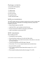
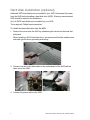
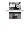
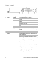
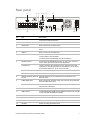
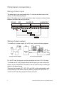
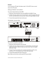
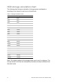
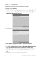
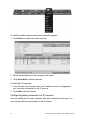
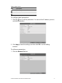
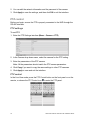
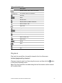
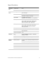
ClareVision
Network Video Recorder
Installation Guide
Model CV-M321620-08
Doc ID 2015-01-622 • Rev 02
Copyright
© 13JAN15 Clare Controls, Inc. All rights reserved.
This document may not be copied in whole or in part or otherwise
reproduced without prior written consent from Clare Controls, Inc.,
except where specifically permitted under US and international
copyright law.
Trademarks
The ClareVision name is a trademark of Clare Controls, Inc.
Other trade names used in this document may be trademarks or
registered trademarks of the manufacturers or vendors of the
respective products.
Version
Contact information
This document applies to CV-M32810-08 ClareVision Network Video
Recorder Rev 2.0.
For contact information, see www.clarecontrols.com.
Note: The figures shown in this manual are for reference only. The appearance
and interface of the device are subject to the actual model.
Content
Package contents...1 NVR pre-installation...1 NVR installation...1 Hard disk installation (optional)...2 Front panel...4 Rear panel...7 Peripheral connections...8 Wiring of alarm input...8 Wiring of alarm output...8 Using of alarm connectors...9 Controller connection...9 HDD storage calculation chart...10 Menu operation...11 Startup and shutdown...11 Using the Setup Wizard...12 Live View...15 Adding and configuring IP cameras...15 Configuring basic parameters of IP cameras...16 PTZ control...18 PTZ settings...18 PTZ control...18 Playback...19 Instant playback by channel...19 Playback by channel...20 Backup...21 Understanding camera capacity in an NVR...23 Streaming video types...23 Adjusting settings...24 Specifications...25 ClareVision Network Video Recorder Installation Guide
i
ii
ClareVision Network Video Recorder Installation Guide
Package contents
1 X 32 channel NVR appliance
1 X AC power cord
1 X optical mouse
1 X remote control
2 X rack mount ears
16 X mounting screws
1 X SATA hard drive cable
NVR pre-installation
This NVR is highly advanced surveillance equipment that should be installed with
care. Please take into consideration the following precautionary steps before
installation of the NVR.
•
Keep all liquids away from the NVR.
•
Install the NVR in a well-ventilated and dust-free area.
•
Ensure environmental conditions meet factory specifications.
•
Install a manufacturer recommended HDD.
NVR installation
When installing the NVR:
•
Use brackets for rack mounting.
•
Ensure that there is ample room for audio and video cables.
•
When routing cables, ensure that the bend radius of the cables is no less than
five times its diameter.
•
Connect both the alarm and RS-485 cable. (Optional)
•
Allow at least .75 in. (2 cm) of space between racks mounted devices.
•
Ensure the NVR is grounded.
•
Environmental temperature should be within the range of 14 to 131 ºF
(-10 to 55 ºC).
•
Environmental humidity should be within the range of 10 to 90%.
ClareVision Network Video Recorder Installation Guide
1
Hard disk installation (optional)
Additional SATA hard disks can be installed in your NVR. Disconnect the power
from the NVR before installing a hard disk drive (HDD). A factory recommended
HDD should be used for this installation.
Up to 8 SATA hard disks can be installed on your NVR.
Tools required: Philips head screwdriver.
To install the hard disk drive into the NVR:
1. Remove the cover from the NVR by unfastening the screws on the back and
side panel.
When installing a SATA hard disk drive, we recommend that the installer wear
anti-static gloves and a grounding wrist-strap.
2. Connect one end of the data cable to the motherboard of the NVR and the
other end to the HDD.
3. Connect the power cable to the HDD.
2
ClareVision Network Video Recorder Installation Guide
4. Place the HDD on the bottom of the device, and then fasten the screws on
the bottom to attach the HDD.
ClareVision Network Video Recorder Installation Guide
3
Front panel
No.
Name
Setting
Function Description
1
Status
indicators
POWER
Turns green when NVR is powered up.
READY
The LED is green when the device is running
normally.
STATUS
The light is green when the IR remote control is
enabled.
The light is red when the function of the composite
keys (SHIFT) are used.
The light is out when none of the above conditions are
met.
2
DVD-R/W
3
Control
buttons
ALARM
The light is red when there is an alarm occurring.
HDD
Blinks red when HDD is reading/writing.
Tx/Rx
Blinks green when network connection is functioning
normally.
Slot for DVD-R/W
DIRECTION
In Menu mode, the direction buttons are used to
navigate between different fields and items and select
setting parameters.
In Playback mode, the Up and Down buttons are used
to speed up and slow down record playing, and the
Left and Right buttons are used to move the recording
30s forwards or backwards.
In the image setting interface, the Up and Down
button can adjust the level bar of the image
parameters.
In Live View mode, these buttons can be used to
switch channels.
ENTER
The Enter button is used to confirm selection in menu
mode; or used to check checkbox fields and ON/OFF
switch.
In Playback mode, it can be used to play or pause the
video.
In Single-frame Play mode, pressing the Enter button
will play the video by a single frame.
In Auto Sequence View mode, the buttons can be
used to pause or resume auto sequence.
4
ClareVision Network Video Recorder Installation Guide
No.
Name
Setting
Function Description
4
Composite
keys
SHIFT
Switch between the numeric or letter input and
functions of the composite keys. (Input letter or
numbers when the light is out; Realize functions when
the light is red.)
1/MENU
Enter the numeral “1”
Access the main menu interface.
2/ABC/F1
Enter the numeral “2”.
Enter the letters “ABC”.
The F1 button when used in a list field will select all
items in the list.
In PTZ Control mode, it will turn on/off PTZ light and
when the image is zoomed in, the key is used to zoom
out.
3/DEF/F2
Enter the numeral “3”.
Enter the letters “DEF”.
The F2 button is used to change the tab pages.
In the PTZ control mode, it zooms in the image.
4/GHI/ESC
Enter the numeral “4”.
Enter the letters “GHI”.
Exit and back to the previous menu.
5/JKL/EDIT
Enter the numeral “5”.
Enter the letters “JKL”.
Delete characters before cursor.
Check the checkbox and select the ON/OFF switch;
Start/stop record clipping in playback.
6/MNO/PLAY
Enter the numeral “6”.
Enter the letters “MNO”.
Playback, for direct access to playback interface.
7/PQRS/REC
Enter the numeral “7”.
Enter the letters “PQRS”.
Open the manual record interface.
8/TUV/PTZ
Enter the numeral “8”.
Enter the letters “TUV”.
Access the PTZ control interface.
9/WXYZ/PREV
Enter the numeral “9”.
Enter the letters “WXYZ”.
Multi-channel display in live view.
0/A
Enter the numeral “0”.
Shift the input methods in the editing text field. (Upper
and lowercase, alphabet, symbols or numeric input).
Double press the button to switch the main and
auxiliary output.
ClareVision Network Video Recorder Installation Guide
5
No.
Name
Setting
5
JOG SHUTTLE control
Function Description
Move the active selection in a menu. It will move the
selection up and down.
In Live View mode, it can be used to cycle through
different channels.
In the Playback mode, it can be used to jump 30
seconds forward/backward in video files.
In the PTZ control mode, it can control the movement
of the PTZ camera.
6
POWER ON/OFF
Power on/off switch.
7
USB interfaces
Universal Serial Bus (USB) ports for additional
devices such as USB mouse and USB Hard Disk
Drive (HDD).
6
ClareVision Network Video Recorder Installation Guide
Rear panel
(2)
(1)
(3)
(4) (5)
(6)
(7)
SW RS-485
ON
KB
ALARM IN
ALARM OUT
eSATA
1
2
3
4
5
6
7
8
9
10
11
12
13
14
15
16
(8)
(9)
(10)
(11)
(12)
(13)
(14) (15)
No.
Item
Description
1
eSATA (Optional)
Connects an external hard drive.
2
RS-232 Interface
Connector for the RS-232 devices.
3
VIDEO OUT
BNC connector for the video output.
4
VGA
VGA output 15 pin connector. Displays the local video output and the
menu.
5
LINE IN
BNC connector for the audio input.
6
Termination Switch
RS-485 termination switch.
The up position is not terminated.
The down position is terminated with 120 Ω resistance.
7
RS-485 Interface
Connector for the RS-485 devices. The T+ and T- pins connect to
the R+ and R- pins of the PTZ receiver respectively.
Controller Port
The D+, and the D- pin connects to the Ta, and the Tb pin of the
controller. For cascading devices, the first NVR’s D+, D- pin should
be connected with the D+, D- pin of the next NVR.
ALARM IN
Connector for alarm input.
ALARM OUT
Connector for alarm output.
8
Network Interfaces with PoE Network interfaces for the cameras and to provide power over
function
Ethernet (PoE).
9
CVBS AUDIO OUT
BNC connector for the audio output. This connector is synchronized
with the CVBS video output.
VGA AUDIO OUT
BNC connector for the audio output. This connector is synchronized
with the VGA video output.
10
HDMI
HDMI video output for the connector.
11
USB interface
Universal Serial Bus (USB) ports for additional devices such as USB
mouse and USB Hard Disk Drive (HDD).
12
LAN Interface
One network interface provided.
13
GROUND
Ground (must be connected when the NVR starts.)
14
AC 100 V to 240 V
AC 100 V to 240 V power supply.
15
POWER
Switch for turning the device on/off.
ClareVision Network Video Recorder Installation Guide
7
Peripheral connections
Wiring of alarm input
The alarm input is an open/closed relay. To connect the alarm input to the
device, use the following diagram.
Note: If the alarm input is not an open/close relay, connect an external relay
between the alarm input and the device.
RS-485
KB
ALARM OUT
ALARM IN
Alarm Input
Alarm Input
Alarm Output
Alarm Output
Wiring of alarm output
To connect to an alarm output (AC or DC load), use the following diagram.
DC Load Connection Diagram
AC Load Connection Diagram
For the DC load, the jumpers can be used within the limit of 12V/1A safely.
To connect an AC load, jumpers should be left open (you must remove the
jumper on the motherboard in the NVR). Use an external relay for safety (as
shown in the figure above).
There are four jumpers (JP1, JP2, JP3, and JP4) on the motherboard, each
corresponding to one alarm output. By default, jumpers are connected. To
connect an AC load, the jumpers should be removed.
8
ClareVision Network Video Recorder Installation Guide
Example:
If you connect an AC load to the alarm output 3 of the NVR, then you must
remove the JP3 jumper.
Using of alarm connectors
To connect alarm devices to the NVR:
1. Disconnect the terminal block from the ALARM IN /ALARM OUT port.
2. Unfasten the stop screws from the terminal block, insert the signal cables into
the slots, and then fasten the stop screws. Ensure the signal cables are tight.
3. Connect the terminal block back into the port.
Controller connection
SW RS-485
ON
ALARM IN
ALARM OUT
eSATA
1
2
3
4
5
6
7
8
9
10
11
12
13
14
15
16
NVR
RS-485
To connect a controller to the NVR:
1. Disconnect the terminal block from the port.
2. Unfasten the stop screws from the D+, D- terminal block, insert the signal
cables into the slots, and then fasten the stop screws. Ensure the signal
cables are in tight.
3. Connect Ta on the controller to D+ on the terminal block and Tb on the
controller to D- on the terminal block. Fasten the stop screws.
4. Connect the terminal block back into the port.
Note: Make sure both the controller and NVR are grounded.
ClareVision Network Video Recorder Installation Guide
9
HDD storage calculation chart
The following chart shows an estimation of storage space used based on
recording at one channel for an hour at a fixed bit rate.
Table 1: Storage calculation chart
Bitrate
Storage Used
96 K
42 M
128 K
56 M
160 K
70 M
192 K
84 M
224 K
98 M
256 K
112 M
320 K
140 M
384 K
168 M
448 K
196 M
512 K
225 M
640 K
281 M
768 K
337 M
896 K
393 M
1024 K
450 M
1280 K
562 M
1536 K
675 M
1792 K
787 M
2048 K
900 M
4096 K
1800 M
8192 K
3600 M
16384 K
7200 M
Note: The values supplied for the storage space used is only for reference. The
storage values in the chart are estimated by formulas and may be different from
the actual value.
10
ClareVision Network Video Recorder Installation Guide
Menu operation
Startup and shutdown
Proper startup and shutdown procedures are crucial to expanding the life of the
NVR.
To start your NVR:
1. Connect to a monitor using VGA or HDMI.
2. Check that the power supply is plugged into an electrical outlet, and then flip
the rear power switch to ON.
We highly recommend that you use an Uninterruptible Power Supply (UPS) in
conjunction with the device.
3. Press the POWER button on the front panel. The Power LED turns green as
the unit starts.
To shut down the NVR:
1. Enter the Shutdown menu (Menu > Shutdown).
2. Select Shutdown.
3. Click Yes.
ClareVision Network Video Recorder Installation Guide
11
Using the Setup Wizard
By default, the Setup Wizard starts once the NVR has loaded.
To operate the Setup Wizard:
1. The Setup Wizard can walk you through some important settings of the NVR.
If you don’t want to use the Setup Wizard at this time, click Cancel. You can
also choose to use the Setup Wizard the next time by selecting the Start
wizard when device starts? checkbox.
2. Click Next on the Wizard window to enter the Login window.
3. Enter the admin username and password. The default username is
“clareadmin”; the default password is “secure7”.
4. To change the admin password, select the New Admin Password checkbox.
Enter the new password and confirm the password in the given fields.
Note: We strongly recommend changing the admin password on initial use.
Record this password in a safe place, if lost the NVR will require a factory
reset.
5. Click Next to enter the date and time settings window.
12
ClareVision Network Video Recorder Installation Guide
6. Enter the correct time zone, date, and time for your location in their
corresponding fields.
7. After the time settings, click Next to enter the Network Setup window.
The internal NIC IPv4 address should be configured for the cameras
connecting to the PoE network interface of the NVR.
8. Click Next to enter the HDD Management window.
ClareVision Network Video Recorder Installation Guide
13
9. To initialize the desired HDD, click Init. Initialization removes all the data
saved in the HDD.
Note: The HDDs are initialized in the factory and are ready to record out of
the box.
10. Click Next. You will enter the Adding IP Camera interface.
11. Click Search to find online IP Camera.
12. Select the IP camera to be added, and then click Add.
13. Click the Next button. Configure the recording settings for the searched IP
Cameras.
14. Click Copy to copy the settings to other channels.
14
ClareVision Network Video Recorder Installation Guide
15. Click OK to complete the Setup Wizard and return to Live View.
Live View
Some icons are provided on the screen in Live View mode to indicate different
camera status. Icons appear at the top right of the screen for each channel. They
show the status of the record and alarm in the channel so that you can identify
problems quickly.
Table 2: Live View icons
Icon
Description
Alarm (video loss, tampering, motion detection or sensor alarm)
Record (manual record, schedule record, motion detection or alarm triggered
record)
Alarm & Record
Adding and configuring IP cameras
Add and configure the online IP cameras to enable the Live View and recording
function.
You can search and add the online IP cameras by following the Startup wizard,
or by following these steps.
To add IP cameras:
1. Right click to enter the Camera Management interface (Menu > Camera >
Camera).
ClareVision Network Video Recorder Installation Guide
15
To add the online cameras with same network segment:
1. Click Search to search the online cameras.
2. Select the checkboxes for the cameras to be added.
3. Click Quick Add to add the cameras.
To add other IP cameras:
1. In the left side of the window, enter the IP address, protocol, management
port, and other information for the IP camera.
2. Click Add to add the camera.
Configuring basic parameters of IP cameras
After the adding the IP camera, the basic information displays on the page. You
can configure the basic parameters of the IP camera.
16
ClareVision Network Video Recorder Installation Guide
Table 3: Basic icons
Icon
Description
Edit basic parameters of the camera
Delete the IP camera
Get the live view of the camera
To configure basic parameters:
1. Click the icon to edit the parameters. You can edit the IP address, protocol,
and other parameters.
2. Click Apply to save the settings, and then click OK to exit the editing
interface.
To edit more parameters:
1. Click the Advance Set icon.
ClareVision Network Video Recorder Installation Guide
17
2. You can edit the network information and the password of the camera.
3. Click Apply to save the settings, and then click OK to exit the interface.
PTZ control
Before you begin, ensure the PTZ is properly connected to the NVR through the
RS-485 interface.
PTZ settings
To set PTZ:
1. Enter the PTZ Settings interface (Menu > Camera > PTZ).
2. In the Camera drop-down menu, select the camera for the PTZ setting.
3. Enter the parameters of the PTZ camera.
Note: All the parameters should match the PTZ camera parameters.
4. Click Copy if you want to copy the same settings to other PTZ cameras.
5. Click Apply to save and exit the interface.
PTZ control
In the Live View mode, press the PTZ Control button on the front panel or on the
remote, or choose the PTZ Control icon
to enter the PTZ panel.
18
ClareVision Network Video Recorder Installation Guide
Table 4: PZT control icons
Icon
Description
Direction button and the auto-cycle button
The speed of the PTZ movement
3D-Zoom
Patrol
Previous item
Stop the patrol or pattern movement
Zoom+, Focus+, Iris+
Light on/off
Image Centralization
Pattern
Next item
Minimize windows
Zoom-, Focus-, IrisWiper on/off
Preset
Menu
Start pattern/patrol
Exit
Playback
Play back the record files of a specific channel in the Live View menu.
Instant playback by channel
Choose a channel under Live View using the mouse, and then click the
in the shortcut operation menu.
button
Note: Only the record files recorded during the last five minutes on this channel
will be played back.
ClareVision Network Video Recorder Installation Guide
19
Playback by channel
To playback by channel:
1. Enter the Playback menu.
Mouse: Right-click a channel in Live View mode and select
from the menu.
Front Panel: Press PLAY to play back the record files of the channel under
single-screen live view.
Under multi-screen live view, record files of the selected channel will be
played back.
Note: Pressing numerical buttons will switch playback to the related channels
for the playback process.
Playback management
The toolbar in the bottom part of Playback interface can be used to control the
playback process.
20
ClareVision Network Video Recorder Installation Guide
Check the channel or channels if you want to switch playback to another
channel, or execute simultaneous playback of multiple channels.
Backup
Recorded files can be backed up to various devices, such as USB flash drives,
USB HDDs, or a DVD writer.
To back up recorded files:
1. Enter the Video Export interface (Menu > Export > Normal).
2. Select the channel(s) you want to back up, set the search condition, and then
click Search to enter the search result interface.
3. In the Search Result interface, select the record files you want to back up,
and then click Export.
4. Enter the Export interface, choose a backup device, and then click Export to
start exporting.
ClareVision Network Video Recorder Installation Guide
21
Note: You can choose to export the record file(s) and the related log file(s), or
the player.
5. Check the backup results. Choose the record file in the Export interface, and
then press to check it.
22
ClareVision Network Video Recorder Installation Guide
Understanding camera capacity in an NVR
When setting up your NVR and cameras, you may notice that some of the
camera images may not display in Live View. This most often occurs when you
are displaying images in 1+5 mode, or 1+7 mode because the total bit rate for all
cameras is exceeding the NVR’s capacity. The actual capacity depends on the
total bit rate from all the cameras. However, it is good practice to allow some
headroom for machine operations, such as remote streaming.
NVR model
Capacity
4-channel
20 Mb
8-channel
40 Mb
16-channel
80 Mb
32-channel
160 Mb
64-channel
160 Mb
To fully understand NVR capacity, it is necessary to understand the concepts of
streaming video, resolution, quality, and bit rate. Streaming video is content sent
in compressed form over a network and processed in real time, that is, as it is
received.
Streaming video types
•
Main Stream: the high quality video that is being recorded and may be
streamed.
•
Sub Stream: never recorded; intended for streaming only. Default is
704 × 480, 584 Kbps at 8 fps.
•
Can be video alone, or video and audio compressed together. Audio requires
very little bandwidth.
The combination of the main stream and sub streams make up the total bit rate
of each camera. This is expressed in Kbps (kilobits per second) or Mbps
(megabits per second).
Bit rate is determined by the selected resolution (1280 × 720, 1920 × 1080,
2560 × 1920, etc.), frame rate (frames per second), and video quality (the
amount of compression being applied to each camera).
Example
32 channels of 720P cameras at 15 fps with good image quality will have
32 x (1536 + 512) = 65536 Kbps (about 66Mbps), so the 32-channel NVR can
support them.
ClareVision Network Video Recorder Installation Guide
23
Each channel can support a different camera, as long as they do not exceed the
total bit rate limit. It is entirely possible to mix 5 MP cameras with 4CIF IP
cameras, etc. Generally, 5 MP at 30 fps requires around 20 Mbps for best
quality. A 4-channel NVR is currently limited to 16 Mbps.
Adjusting settings
Be aware of your NVR’s capacity and make adjustments, if necessary. Adjust the
bit rate by lowering the resolution, frame rate, or video quality setting.
To adjust the setting:
1. Enter the Live View settings interface.
2. Adjust the Resolution, Frame Rate, and Video Quality settings.
24
ClareVision Network Video Recorder Installation Guide
Specifications
Video/Audio
input
Video/Audio
output
IP video input
32-ch
Two-way audio
1-ch, BNC (2.0 Vp-p, 1k Ω)
Recording resolution
5 MP /3 MP /1080P /UXGA /720P /VGA /4CIF /DCIF
/2CIF /CIF /QCIF
Frame rate
Main stream: 25 fps (P) / 30 fps (N)
Sub-stream: 25 fps (P) / 30 fps (N)
CVBS output
1-ch, BNC (1.0 Vp-p, 75 Ω)
Resolution: 704 × 576 (PAL); 704 × 480 (NTSC)
HDMI output
1-ch, resolution:
1920 × 1080P / 60 Hz, 1920 × 1080P / 50 Hz,
1600 × 1200 / 60 Hz, 1280 × 1024 / 60Hz,
1280 × 720 / 60 Hz, 1024 × 768 / 60 Hz
VGA output
1-ch, resolution:
1920 × 1080P / 60 Hz, 1600 × 1200 / 60 Hz,
1280 × 1024 / 60 Hz, 1280 × 720 / 60 Hz,
1024 × 768 / 60 Hz
Audio output
2-ch, BNC (Linear, 600 Ω)
Playback resolution
5 MP /3 MP /1080P /UXGA /720P /VGA /4CIF /DCIF
/2CIF /CIF /QCIF
Synchronous playback 16-ch
Hard disk
External
interface
SATA
4 SATA interfaces for 2 HDDs + 1 DVD-R/W
(default), or 4HDDs
eSATA
1 eSATA interface
Capacity
Up to 4TB capacity for each HDD
Network interface
1 RJ-45 10 /100 /1000 Mbps self-adaptive Ethernet
interface
32 independent 100 Mbps PoE network interfaces
Serial interface
RS-232; RS-485; Keyboard
USB interface
3 × USB 2.0
Alarm in
16
Alarm out
4
ClareVision Network Video Recorder Installation Guide
25
Others
26
Power supply
100 to 240 VAC, 6.3 A, 50 to 60 Hz
Consumption
(without hard disk
or DVD-R/W)
≤ 45 W
Working temperature
14 to 131ºF (-10 to 55 ºC).
Working humidity
10 to 90 %
Chassis
19-inch rack-mounted 2U chassis
Dimensions
(W × D × H)
17.5 × 15.4 × 3.5 (44.5 × 39.0 × 9.0 cm)
Weight
≤ 8.82 lb (4 Kg) (without hard disk or DVD-R/W)
ClareVision Network Video Recorder Installation Guide