1
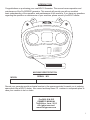
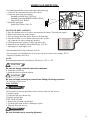
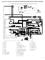
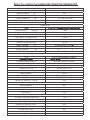
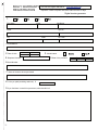
BOLIY POWER
OWNERS MANUAL
MODEL
Pro3600Si
Pro3600Si/E
Electric Start
DIGITAL GENERATOR
DSP TECHNOLOGY
TABLE OF CONTENTS
PLEASE READ ENTIRE MANUAL BEFORE OPERATING
Introduction ....................................................................................1
Warranty ........................................................................................2-3
Safety Information ............................................................................4-5
Exhaust Fumes Are Poisonous
Never Run Generator Indoors
Fuel is Highly Flammable and Poisonous
Engine and Muffler May be Hot
Electric Shock Prevention
Connection Notes
Extension Cord Notes
Battery
Control Function ................................................................................6-7
Description and Control Panel Key
Oil Warning System
Engine Switch
DC Protector
Pre-Operation Check...........................................................................8
Fuel System
Refueling and Fuel Level Gauge
Engine Oil
Ground (Earth)
Operation............................................................................................9-12
Starting the Engine
Economy Control Switch
Application Range
Connection
Stopping the Engine
Periodic Maintenance.........................................................................13
Maintenance Chart
Spark Plug Inspection.........................................................................14
Engine Oil Replacement
Fuel Filter
Fuel Tank Filter
Troubleshooting.................................................................................15
Engine won’t Start
Generator won’t produce power
Storage
Drain the fuel
Engine
Specifications...................................................................................16
Wiring Diagram...................................................................................17
Grounding Information .......................................................................18
Portable Generator Hazards ...............................................................19
Appendix............................................................................................20
INTRODUCTION
Congratulations on purchasing your new BOLIY Generator. This manual covers operation and
maintenance of the Pro3600Si/E generator. This manual will provide you with an excellent
basic understanding of the operation, and maintenance of this machine. If you have any questions
regarding the operation or maintenance of your machine, please consult your BOLIY dealer.
xxx-xxxxx
MACHINE IDENTIFICATION
MODEL
SERIAL NO.
Record your generator model and serial number in the spaces provided, to assist you in ordering
spare parts from a BOLIY dealer. Also record and keep these I.D. numbers in a separate place in
case your machine is lost or stolen.
Pro3600 SI & SiE
OWNER’S MANUAL
7th Edition, June, 2010
All rights reserved.
www.boliypower.com
1
2 YEAR FULL RUNABILITY & EMISSIONS COVERAGE
BOLIY POWER WARRANTY POLICY
This warranty is limited to Boliy products when distributed by Boliy Power. The following warranty applies to products
purchased at retail or for recreational use after January 1, 2010.
Warranty Procedure:
Congratulations on your purchase of a Boliy Generator. There are 2 ways to register your machine.
1.
2. Complete your warranty registration cards and mail to:
Register your machine online:
Website: www.boliypower.com.
or
Boliy Power America,
PO BOX 007 Iselin,
NJ 08830-0007
or
Suzhou Zhonggu Mould Co., Ltd.
Huangqiao Industrial Park,
Suzhou Jiangsu,
215132,China
Tel: +86-512-65466507
Please note that your warranty coverage is valid only if we have received a copy of your card.
BOLIY hereby warrants that new BOLIY consumer
generator purchased from an authorized BOLIY
consumer generator dealer will be free from defects
in material and workmanship for the period of time
stated herein subject to certain stated limitations.
THE PERIOD OF WARRANTY Any new SI Series or SIE - Series BOLIY Generator purchased for
private, non- commercial use from an authorized
BOLIY consumer generator dealer will be warranted
against defects in material or workmanship for a
period of two years from date of purchase, subject to
exclusions noted herein. Any BOLIY non-commercial
generator purchased and utilized for commercial or
rental applications will be warranted for a period of
one year from the date of purchase, subject to
exclusions noted herein.
DURING THE PERIOD OF WARRANTY any
authorized BOLIY consumer generator dealer will,
free of charge, repair or replace, at BOLIY’s
option, any part judged defective by BOLIY due
to faulty workmanship or material from the factory.
Parts used in warranty repairs will be warranted for
the balance of the product’s warranty period. All
parts replaced under warranty become property of
BOLIY.
GENERAL EXCLUSIONS from this warranty
shall include any failures caused by:
a. Installation of parts or accessories that are
not qualitatively equivalent to genuine
BOLIY parts.
b. Abnormal strain, neglect, or abuse.
c. Lack of proper maintenance.
d. Accident or collision damage.
2
SPECIFIC EXCLUSIONS from this warranty
shall include parts replaced due to normal wear or
routine maintenance.
THE CUSTOMER’S RESPONSIBILITY under
this warranty shall be to:
1. Operate and maintain the generator as specified
in the appropriate Owner’s Manual
2. Give notice to an authorized BOLIY consumer
generator dealer of any and all apparent defects
within ten days after discovery, and make the
unit available at that time for inspection and
repairs at such dealer’s place of business.
BOLIY MAKE NO OTHER WARRANTY OF ANY
KIND, EXPRESSED OR IMPLIED. ALL IMPLIED
WARRANTIES OF MERCHANTABILITY AND FITNESS FOR A PARTICULAR PURPOSE WHICH
EXCEED THE OBLIGATIONS AND TIME LIMITS
STATED IN THIS WARRANTY ARE HEREBY DISCLAIMED BY BOLIY EXCLUDED FROM THIS
WARRANTY.
SOME STATES DO NOT ALLOW LIMITATIONS ON
HOW LONG AN IMPLIED WARRANTY LASTS, SO
THE ABOVE LIMITATION MAY NOT APPLY TO YOU.
ALSO EXCLUDED FROM THIS WARRANTY ARE
ANY INCIDENTAL OR CONSEQUENTIAL DAMAGES
INCLUDING LOSS OF USE. SOME STATES DO NOT
ALLOW THE EXCLUSION OR LIMITATION OF INCIDENTAL OR CONSEQUENTIAL DAMAGES, SO THE
ABOVE EXCLUSION MAY NOT APPLY TO YOU.
THIS WARRANTY GIVES YOU SPECIFIC LEGAL
RIGHTS, AND YOU MAY ALSO HAVE OTHER
RIGHTS WHICH VARY FROM STATE TO STATE.
- BOLIY POWER
- In a case the generator needs to be sent to a
service center it is important to keep all of the
original packaging materials.
WARRANTY QUESTIONS AND ANSWERS
Q. What costs are my responsibilities during the
warranty period?
of normal maintenance service, non-warranty
repairs, accident damages, as well as oil and
spark plugs.
Q. What are some examples of “abnormal” strain,
neglect, or abuse?
A. These terms are general and overlap each other
in areas. Specific examples include: Running
the machine out of oil; lack of proper maintenance; operating the machine with a broken or
damaged part which causes another part to fail;
and so on. If you have any specific questions on
operation or maintenance, please contact your
dealer for advice.
Q. Does the warranty cover incidental costs such as
transportation due to a failure?
A. Y es. If it is determined that it is an emmissions
related problem.
A. No. If it is a warranty claim that is not
emmissions related.
Q. What responsibility does my dealer have under
this warranty?
A. Each BOLIY generator dealer is expected to:
1. Check the operation of the generator before sale.
2. Explain the operation, maintenance, and
warranty requirements to your satisfaction at the
time of sale, and upon your request at any later
date.
CUSTOMER SERVICE
In the event that something goes wrong with your
Boliy Generator, our authorized team of technicians
are available to help you get your Boliy Generator
back up and running as quickly as possible. To take
full advantage of our service center please chose one
of the following options for your repair:
1) For the fastest service, you may exchange your
unit for a ready to go unit of equal age and
condition. A $500 deposit will be required and will
be refunded when the defective unit is returned. All
replacement units will be shipped within 24 hours.
2) Return your defective unit and it will be repaired
within 10 days and returned to you at no charge.
CHANGE OF ADDRESS
The federal government requires each manufacturer
to maintain a complete, up-to-date list of all first
purchasers against the possibility of a safety-related
defect and recall. This list is compiled from the
low the procedures specified ed in the Owner’s and
purchase registrations sent to BOLIY. If you should
Service Manual. We do recommend, however,
move after you have purchased your new generator,
that items requiring special tools or equipment
please advise us of your new address by sending a
be done by a BOLIY generator dealer.
post-card listing your BOLIY model name, engine
number, and dealer name as it is shown on your
Q. Will the warranty be void or cancelled if I do not warranty identi cation, your name and new mailing
address. Mail to:
operate or maintain my new BOLIY exactly as
specifi ed in the Owner’s Manual?
A. Y es. The warranty on a new BOLIY can be
Suzhou Zhonggu Mould Co., Ltd.
Boliy Power America,
Huangqiao Industrial Park,
or
“voided” or “cancelled”.
PO BOX 007 Iselin,
Suzhou Jiangsu,
If a particular failure is caused by operation or
NJ 08830-0007
215132,China
Tel: +86-512-65466507
maintenance other than as shown in the Owners
Manual, that failure will not be covered under
warranty.
This will ensure that BOLIY has an up-to-date
registration record in accordance with federal law.
Q. May I perform any or all of the recommended
maintenance shown in the Owner’s Manual instead of having the dealer do them?
A. Yes, if you are a qualifi ed mechanic and fol-
3
SAFETY INFORMATION
WARNING
EXHAUST FUMES ARE POISONOUS. Never operate the engine in a close area or it may cause
unconsciousness and death within a short time. Operate the engine in a well ventilated area.
NEVER RUN GENERATORS INDOORS OR IN CONFINED SPACES.
•Never sleep a running generator due to the emission of carbon monoxide.
•When working with a generator, keep at least 20 feet away from where it is running.
•Keep generators clear of all fresh air inlets (houses, buildings, campers, or tents) to avoid possible
carbon monoxide poisoning.
•Failure to adhere to these precautions could result in POISONING or possibly even DEATH
FUEL IS HIGHLY FLAMMABLE AND POISONOUS
•Always turn off the engine when refueling.
•Never refuel while smoking or in the vicinity of an open flame.
•Take care not to spill any fuel on the engine or muffler when refueling.
• If you swallow any fuel, inhale fuel vapor, or allow any to get in your eyes, see your doctor immediately.
If any fuel spills on your skin or clothing, immediately wash soap and water and change your clothes.
• When operating or transporting the machine, be sure it is kept upright. If it tilts, fuel may leak from the
carburetor or fuel tank.
ENGINE AND MUFFLER MAY BE HOT
•Place the machine in a place where pedestrians or children are not likely to touch the machine.
•Avoid placing any flammable materials near the exhaust outlet during operation.
•Keep the machine at least 1 meter/3 feet from buildings or other equipment, or the engine may overheat.
•Avoid operating the engine with a dust cover.
ELECTRIC SHOCK PREVENTION
•Never operate the engine in rain or snow.
•Never touch the machine with wet hands or electrical shock will occur.
•Be sure to ground (Earth) the generator.
CONNECTION NOTES
Avoid connecting the generator to commercial power outlet. Avoid connecting the generator in parallel
with any other generator.
WARNING
Before the generator can be connected to a building’s electrical system, a licensed electrician
must install an isolation (transfer) switch in the building’s main fuse box. The switch is the connection point for generator power and allows selection of generator or main line power to the
building. This will prevent the generator from charging the main power line (backfeeding) when
the main power supply has failed or has been turned off for line repair. Backfeeding can electrocute or injure line maintenance personnel. Also, generator and building electrical system damage
can occur when normal operating power returns if unit is used without an isolation switch.
EXTENSION CORD NOTES
•When using an extension cord, is total length should not exceed 50 feet with 12 gauge wire or up to 100
feet with 10 gauge wire.
•This extension cord should be protected by a tough flexible rubber sheath (IEC 245) or the equivalent to
withstand mechanical stresses.
4
BATTERY
Battery
This generator is equipped with a sealed type (MF) battery, which does not require any maintenance.
There is no need to check the electrolyte or to add distilled water.
Battery preparation
1. Open the front door.
2. Check the positive lead (red) connection to the positive (+) terminal.
3. Connect the negative lead (black) to the negative (-) terminal.
4. Close the front door.
To charge the battery
Have a Boliy dealer charge the
battery as soon as possible if it
seems to have discharged.
Recommended battery
Recommended battery:
Capacity: 12V/4.5Ah or 12V 5Ah
Size: L90*W70*H102mm
+ Do
CA
UT
ba not
IO
c
t
t
yo ery onn
N
u s ca ec
tar ble t n
t to
u eg
us ntil ative
et
he
ma
ch
ine
!
WARNING
Electrolyte is poisonous and dangerous since it contains sulfuric acid, which causes severe burns.
Avoid any contact with skin, eyes or clothing and always shield your eyes when working near batteries.
In case of contact, administer the following FIRST AID.
EXTERNAL: Flush with plenty of water.
INTERNAL: Drink large quantities of water or milk and immediately call a physician.
EYES: Flush with water for 15 minutes and seek prompt medical attention.
Batteries produce explosive hydrogen gas. Therefore, keep sparks, flames, cigarettes, etc., away from
the battery and provide sufficient ventilation when charging it in an enclosed space.
KEEP THIS AND ALL BATTERIES OUT OF THE REACH OF CHILDREN.
Battery Storage
1. Remove the battery.
2. Store the battery in a cool, dark and dry place. Do not store the battery in an excessively warm or cold
place [i.e., less than 0°C (30°F) or more than 30°C (90°F)].
WARNING
Disconnect the negative lead (black) first, then the positive lead (red) from the battery.
Connect the positive lead (red) first, then the negative lead (black) to the battery when installing the
battery.
5
CONTROL FUNCTION
1
1
3
2
16
D IG ITA L
ON
STOP
ENG INE
STA RT
ECO N
TE CH
14
ON
10
O N OFF
(PUS H)
T OR
PR O TEC
OFF
TO RESE TAC INE
RESTART ENG
ON
OFF
AC
12
15
11
13
5
4
7
8
9
6
Description and Control Panel Key
1.
2.
3.
4.
5.
6.
7.
8.
Carrying Handles
Fuel Level Gauge
Fuel Cap and Vent
Fuel On/Off Switch
AC Ready Pilot Light
Oil Warning Light
Ground (Earth) Terminal
30 Amp Receptacle
9. 30 Amp RV Receptacle
10. Engine On/Off Switch
11. Choke Knob
12. Economy Control Switch
(SMART throttle switch)
13. Recoil Starter
14. DC Outlet and Reset Button
15. Oil Fill Access Door Panel
16. Engine Start button
6
CONTROL FUNCTION CONTINUED
OIL WARNING SYSTEM
If the oil level falls below the safe operating level, the engine will stop automatically. Unless you refill with
oil, the engine will not start again.
NOTE:
If the engine stalls or does not start, turn the engine switch to “ON” position and then pull the recoil starter. If
the oil warning light flickers for a few seconds, the engine oil is low. Add oil and restart.
ON
A
ENGINE SWITCH
STOP
The engine switch controls the ignition system.
A. Ignition circuit is switched on.
The engine can be started.
B
B. Ignition circuit is switched off.
The engine will not run.
DC PROTECTOR
The DC Protector turns of automatically when the loads exceeds the generator rated output.
ON
OFF
(PUSH)
PROTECTOR
NOTE:
If the DC Protector trips to the OFF position, press to reset. Reduce the load to the specified generator output if
the DC protector turns off. If it turns off again, consult the authorized dealer.
7
PRE OPERATION CHECKLIST
NOTE:
Pre-operation checks should be made each time the generator is used.
FUEL SYSTEM
Make sure there is sufficient fuel in the tank.
Recommended fuel: Unleaded gasoline
Fuel tank capacity: Total 2.1 US Gallons
The engine must use regular unleaded gasoline with a pump octane number (R+M)/2) of 86 or higher, or research octane
number of 91or higher. E-85 is NOT recommended.
REFUELING AND FUEL LEVEL GAUGE
E
F
Fuel Level Gauge
“F”
Full
“E”
Empty
E
F
To refuel, remove cap and fuel slowly until fuel gauge indicates full.
WARNING
• Fuel is high flammable and poisonous. Check “SAFETY INFORMATION” carefully before refueling.
• DO not fill above the top of fuel filler or it may overflow when the fuel the fuel heats up later and
expands.
• Wipe up any spilled fuel immediately.
• After refueling, make sure the tank cap is tightened.
ENGINE OIL
Make sure the engine oil is at the upper level of the oil filler hole. Add oil as necessary.
Recommended oil for most climates: 10W 30
For extremely cold conditions the oil viscosity may be lowered to ease starting: 5W 30
Engine Oil Quantity: 0.63 US qt
NOTE:
Recommended engine oil classification: API Service “SE” or “SF”; if not available, “SD”
CAUTION
The generator has been shipped without engine oil. Fill with oil or it will not start.
GROUND (EARTH)
Make sure to ground (Earth) the generator. SEE PAGE 17.
8
OPERATION
STARTING THE ENGINE
NOTE:
Before starting the engine, do not connect any electric devices.
1. Turn the fuel switch lever to the “ON” position.
2. Turn the engine switch to the “ON” position.
3. Please make sure fix cathcode cable to the crank case(Electric start model).
3.
ON
2.
1.
A
ON
STOP
+ -
OFF
B
Do
CA
UT
ba not
IO
yo ttery conn
N
u s ca ec
tar ble t n
t to
un ega
tive
us til
et
he
ma
ch
ine
!
Note: Sometimes the choke is required to start a warm engine.
3. Hold the choke knob fully out.
4. Pull slowly on the recoil starter until it is engaged, then pull it briskly. (Electric start model can press engine
start button to start.)
5. After the engine starts, warm up the engine until the engine does not stop when the choke knob is returned
to the original position.
6. Push the choke knob back to the original position.
D I G I TA L
ENGINE
START
KE
KE
CHO
ON OFF
(PUSH)
F
OF
CHO
T E C H
F
OF
PROTECTOR
NO
F
OF
NO
NO
ECONOMY CONTROL SWITCH (120V/60Hz type have this switch)
Engine speed is kept at idle automatically when the electrical device is disconnected and is returned to the
proper speed by the electrical load when the electrical device is reconnected. The economy control switch in
“ON” position is recommended to minimize the fuel consumption while in normal operation.
NOTE:
When high electrical load devices are connected simultaneously, turn the economy control switch to the “OFF”
position, the engine speed will increase to reduce voltage changes. Otherwise the generator will not operate
sufficiently to run high demand electrical devices.
9
OPERATION CONTINUED
AC CONNECTION
ALTERNATING CURRENT (AC)
CAUTION
• Be sure electric devices including the lines and plug connections are in good condition
before connection to the generator.
• Be sure any electric devices are turned off before plugging it in.
• Be sure the total load is within generator rated output.
• Be sure the receptacle load current is within receptacle rated current.
1. Wind the power lead 2 or 3 turns around the carrying handle.
2. Start the engine.
3. Plug in to the AC receptacle.
4. Make sure the AC indicator light is on.
5. Turn on any electric devices.
OVERLOAD INDICATOR LIGHT
The overload indicator light (the AC pilot light) will flash when an overload of connected electrical device is
detected or the inverter control unit overheats. The electronic breaker will then activate, stopping power
generation in order to protect the generator and any connected electric devices, but the engine will not stop
running.
When the overload indicator light comes on and power generation stops, proceed as directed:
1. Turn off any connected electric devices and stop the engine.
2. Reduce the total wattage of connected electric devices within the application range.
3. Check for blockages in the cooling air inlet and around the control unit. If any blockages are found, remove.
4. After checking, restart the engine.
Note: The highest peak load on this model is 3600 watts, the short term peak load is 3300 watts and the
max operating load is 3,000 watts. High temperatures or high elevations will reduce the expected performance
of this generator.
NOTE:
The generator AC output automatically resets when the engine is stopped and restarted.
USING THE GENERATOR FOR BATTERY CHARGING
CAUTION
Do not use AC and DC power at the same time or the generator may be damaged.
NOTE:
The generator DC rated voltage is 12 V.
1. Start Engine
2. Plug in battery charge wires to D.C. receptacle-#14 on CONTROL FUNCTION DIAGRAM
NOTE:
• Make connections to the battery after starting the engine
• Clamp the red wire to the positive(+)terminal and the black wire to the negative(-)terminal of the battery.
Do not reverse these positions.
10
OPERATION CONTINUED
CAUTION
• Be sure the battery leads are properly connected and is not damaged or obstructed.
• Be sure breather hose is properly connected and is not damaged or obstructed.
• Reduce the load to the specified generator rated output if the DC protector turns off.
If it turns off again, consult the authorized dealer.
NOTE:
• If short or overdraw should occur in the system, it will cause the DC Protector to trip. Press to reset
the DC protector.
NOTE:
• At full charge, electrolyte specific gravity is between 1.26 and 1.28
• Check specific gravity hourly.
WARNING
Never smoke near the battery while charging. Do not make or break connections while the
battery is charging. This may cause sparks to ignite the battery gas. Battery acid is poisonous
and dangerous; it contains sulfuric acid. Avoid contact with skin, eyes, and clothing as it will
cause severe burns.
If contact occurs:
EXTERNAL - Flush with water.
INTERNAL - Drink large quantities of water or milk, then drink milk of magnesia beaten egg or
vegetable oil. Call physician immediately.
EYES - Flush with water for 15 minutes and get prompt medical attention.
Batteries produce explosive gases. Keep sparks, flame, cigarettes, etc., away from the generator.
Ventilate when charging or using in closed space. Always cover eyes when working near batteries.
KEEP OUT OF REACH OF CHILDREN.
STOPPING THE ENGINE
1. Disconnect any electric devices.
2. Turn the engine switch to the “STOP” position.
3. Turn the fuel lever to “OFF”
1.
2.
STOP
11
ON
3.
OPERATION CONTINUED
APPLICATION RANGE: APPROXIMATE WATTAGE REQUIRED FOR STARTING
Coffee Maker
Dishwasher
-Cool Dry
Electric Fry Pan
Electric Range
-8- inch element
Microwave Oven
20”Box Fan or Table Fan
Electric Blanket
Refrigerator
Automatic Washer
Clothes Dryer
-Electric
Furnace Fan, gas or fuel oil
1/8 Horsepower
1/4 Horsepower
½ Horsepower
Lights (as indicated on bulb)
Radio
Sump Pump
1/3 Horsepower
½ Horsepower
Television
-color
RV Air Conditioner
13,500 BTU
Room Air Conditioner
10,000 BTU
Contractor
Air Compressor
-1 Horsepower
Bench Grinder
-8 inches
Hand Drill
-1/2 inch
High-Pressure Washer
-1 Horsepower
Circular Saw, Heavy Duty
-7 1/4 inches
Household RV
1750
1750
700
1300
1400
1300
2100
1000
120
150
192
1150
2100
2100
180
150
1200
2300
5750
1800
300
600
875
500
1000
2350
50-200
50
800
1050
1300
2150
300
300
1800
2800
1500
2200
1500
4500
1400
2500
600
600
1200
3600
1400
2300
Household RV
Electric Chain Saw
1100
1000
- 14 inces,2HP
Table Saw
- 10 inches
1800
4500
Drills
-3/8 inch,4 amps
440
600
-1/2 incn,5.4 amps
600
900
Capacitor Start induction Run
-1/3 Horsepower
720
1300
-1 Horsepower
1600
4500
Capacitor Start Capacitor Run
-1 1/2 Horsepower
2000
6100
Fan Duty
-1/6 Horsepower
550
850
Farm Equipment
Electric Fence,25 miles
250
230
Milk Cooler
1100
1800
Milkier (vacuum pump)
-2 Horsepower
1000
2300
Portable Heater(kerosene, diesel fuel)
-50,000BTU
400
600
-90,000BTU
500
725
-150,000 BTU
625
1000
Battery Charger
-15 amp
380
380
-60 amp/250-amp boost
1500/5750
1500
-100 amp/300-amp boost
2400/7800
2400
Electric Welder
-200 amp AC
9000
9000
-230 amp AC, at 100 amp
7800
7800
Air Compressors
-1/2 Horsepower
975
1600
-1 Horsepower
1600
4500
Computers
-Desktop
600to800
600
-Laptop
600to250
200
-Monitor
200to250
200
Fax
600to800
600
Printer
400to600
400
NOTE:
• Application wattage indicates when each device is used by itself
CAUTION
• Be sure the total load is within generator rated output otherwise generator damage may occur.
• Do not use AC and DC power at the same time or the generator may be damaged
NOTE:
Some precision equipment is voltage sensitive and may require a uniform voltage supply than portable
genera-torso provide Examples include some medical equipment, personal computers, and some
inverters that sense peak and RMS voltage values. Consult the precision-equipment vendor before
relying on any portable generator to provide power to such equipment.
12
PERIODIC MAINTENANCE
MAINTENANCE CHART
Regular maintenance is most important for the best performance and safe operation.
WARNING
Stop the engine before starting maintenance work.
Item
Remark
Spark Plug
Check condition. Adjust
gap and clean. Replace if
necessary.
Engin Oil
Check oil level/Replace
Air Filter
Initial 1 month
/20 Hours
Every 3 Month
/50 Hours
Every 6Month
/100 Hours
Every 12Month
/300 Hours
Clean/Replace if
necessary
Fuel Filter
Clean fuel cock and fuel
tank filter. Replace if
necessary.
Value Clearance
Check and adjust
when engine is cold.
Fuel Line
Check fuel hose for crack
or damage. Replace if
necessary.
Exhaust System
Pre-Operation
Check (Daily)
Check for leakage.
Re-tighten or replace
gasket if necessary.
Check muffler screen.
Clean/replace if
necessary.
Choke Handle Check choke’s operation.
Cooling System Check fan damage.
Starting System
Check recoil starter
operation.
Decarburization
More frequently if
necessary.
Check the pilot light
comes on.
Generation
Fittings
/Fasteners
Check all fittings and
fasteners. Correct if
necessary.
CAUTION
Use only genuine BOLIY replacement parts. If you have questions, contact your dealer
or Boliy USA (651-407-1457)
13
SPARK PLUG INSPECTION
You should periodically remove and inspect the spark plug.
1. Check for discoloration and remove the carbon.
2. Check the spark plug type and gap.
Standard electrode color: Tan Color
Standard Spark Plug:BPR4ES(NGK)(F7RTC)
Gap:(0.028-0.031 inches)
3. Install the spark plug.
Spark Plug Torque:14 lbs. -Ft.
(0.028-0.031 inch)
ENGINE OIL REPLACEMENT
1. Place the machine on a level surface and warm up the engine. Then stop the engine.
2. Remove the rubber cap on the bottom..
3. Place an oil pan under the engine. Remove the drain bolt
4. Open the oil filler cover as shown and remove the oil filler
cap so that the oil can be completely drained.
5. Check the drain bolt, gasket, oil filler gap and O-ring.
6. Reinstall the oil drain bolt.-Drain Bolt Torque:12 Ft. lbs.
7. Add engine oil to the upper level.
• Recommended oil for most climastes:10 W30
• For extremely cold conditions the oil viscosity may be lowered to ease starting: 5W 30
• Engine Oil Quantity:0.63US qt
NOTE:
Recommended engine oil classification: API Service “SE” or “SF”
CAUTION
Be sure no foreign material enters the crankcase.
8. Install the oil filler cap.
9. Install the rubber cap on the bottom.
CAUTION
Be sure to install securely to prevent from falling off during operation.
10. Close the oil filler cover.
FUEL FILTER
WARNING
Do not smoke or have an open flame in the vicinity of the fuel and solvent.
1.Stop the engine:
2.Clamp the fuel line with the clip.
3.Replace the fuel filter.
FUEL TANK FILTER
1. Remove the fuel tank cap and filter.
2. Clean the filter with solvent, if damaged, replace.
3. Wipe the filter and insert it.
WARNING
Be sure the tank cap is securely tightened.
14
TROUBLESHOOTING
ENGINE WON’T START
1. Fuel system, engine is not getting fuel.
• No fuel in tank... Supply fuel.
• Clogged fuel line... Clean fuel line.
• Foreign matter in fuel filter... Replace fuel filter.
• Clogged carburetor... Clean carburetor.
2. Engine oil light flashes
• Oil level is low... Add engine oil.
3. Electrical system
• Engine switch to “ON”. Poor or no spark.
• Spark plug is dirty... Replace sparkplug.
• Faulty ignition system... Consult dealer.
4. Compression Insufficient
•Worn out piston and cylinder... Consult dealer.
GENERATOR WON’T PRODUCE POWER
Stop the engine, then restart. If A/C lights continue to flash consult your dealer.
STORAGE
Long term storage of your machine will require some preventive procedures to guard against
deterioration.
DRAIN THE FUEL
1. Remove the fuel tank cap. Drain the fuel tank into an approved gasoline container using a
commercially available hand siphon. Then, install the fuel tank cap.
WARNING
• Fuel is highly flammable and poisonous.
• Wipe up any spilled fuel immediately.
2.Drain fuel from the carburetor by loosening the drain screw on the carburetor float chamber.
3.Turn the fuel cock lever to “OFF”. Start the engine and leave it run until it stops.
This will burn any remaining fuel in the carburetor.
ENGINE
1. Remove the spark plug, pour about one tablespoon of SAE 10W30 or 20W40 motor oil into
the spark plug hole and reinstall the spark plug. Turn over engine several times (with
ignition off) to coat the cylinder walls with oil.
2. Pull the recoil starter until you feel compression. The stop pulling. (This prevents the
cylinder and valves from rusting).
3. Clean exterior of the generator and apply a rust inhibitor.
4. Store the generator in a dry, well-ventilated place, with the cover placed over it.
5. The generator must remain in a vertical position when stored, carried or operated.
15
BOLIY Pro 3600Si & 3600Si/E DSP INVERTER GENERATOR WIRING DIAGRAM
Color code
B - Black
G - Green
L - Blue
O - Orange
R - Red
W - White
Y - Yellow
P - Pink
B/W - Black/White
G/Y - Green/Yellow
W/L - White/Blue
1 - Main coil
2 - Sub coil
3 - Control unit
4 - AC indicator light/
Overload indicator light
5 - AC receptacle
6 - Ground (Earth) terminal
7 - Economy Control Switch
8 - Step Motor controller
9 - Engine switch
10 - Oil warning light
11 - Oil warning unit
12 - Oil level gauge
13 - Ignition coil
14 - Spark plug
15 - AC-CDI unit
16 - Pulsar coil
17 - Stepping motor
18 - Charge coil
19 - DC receptacle
20 - Ballast
16
BOLIY Pro 3600Si/ Pro3600SiE DSP INVERTER GENERATOR
SPECIFICATIONS & DIMENSIONS
OVERALL LENGTH
(in)
23
OVERALL WIDTH
(in)
16.5
OVERALL HEIGHT
(in)
18.5
DRY WEIGHT
(lb..)
SHIPPING WEIGHT
3600 SI - 68 lbs, 3600 SI/E - 74 lbs
(lb.)
SI - 72lbs, SI/E -78lbs
FUEL TANK CAPACITY (US gal.)
NOISE LEVEL
2.1
(1/4 load at 7m)
53-58 dB
GENERATOR
RATED OUTPUT
(WATTS)
3000
MAX OUTPUT
(WATTS)
3300
FULL TANK OUTPUT
(WATTS)
13500
RUN TIME AT 1/2 RATED LOAD
7.5 hours
RUN TIME AT RATED LOAD
4 hours
POWER CONVERSION RATE
85-92%
RATED FREQUENCY
(Hz)
60
50
RATED CURRENT
(A)
25
13
DC OUTPUT
(12V/8A)
YES
ENGINE
/ELECTRIC START
CYLINDER ARRANGEMENT
BORE X STROKE
INCLINED, SINGLE CYLINDER
(mm)
66 X 50
IGNITION SYSTEM
CDI
SPARK PLUG TYPE
GAP
TC
(in)
0.8 (0.028 - 0.031)
DISPLACEMENT
RATED OUTPUT
BPR4ES (NGK) / F7R
171CC
(HP) r/min
(4.9) / 3600
FUEL
UNLEADED GASOLINE
ENGINE OIL QUANTITY (US qt)
-0.63
THE FLUCTUATION OF VOLTAGE & FREQUENCY
INSTANTANEOUS
25%
STABLE STATE
0%
STABLE TIME
(second)
3
FREQUENCY
0.2%
CHARACTERISTIC
AUTOMATIC RELEASE PRESSURE
ELECTRO-BREAKER
YES
FUEL LEVEL GAUGE
YES
ENGINE OIL WARNING LIGHT
YES
OVERLOAD INDICATOR LIGHT
NO
AC INDICATOR LIGHT
YES
ENERGY CONSERVATION CURRENT IDLING
INSULATION CLASS
17
YES
YES
F
ADDITIONAL GROUNDING INFORMATION & SAFETY TIPS
MAJOR CAUSES OF INJURIES AND FATALITIES
• Shocks & electrocution to users from improper use-improper connection to structures, such as
residences, offices, shops and trailers.
SAFE WORK PRACTICES
• Maintain and operate generators in accordance with the manufacturer’s use and safety instructions.
• Do not attach a portable generator directly to the electrical system of a structure(home,office or
trailer) unless the generator has a properly installed open-transition transfer switch.
• Always plug electrical appliances and tools directly into the generator using manufacturers supplied
cords. Use heavy duty extension cords that contain a grounding conductor(3-wire flexible cord and
3-pronged cord connectors).
• Proper grounding and bonding prevent shocks and electrocutions.
• Use ground-fault circuit interrupters(GFCIs)as per the manufacturer’s instructions.
• Visually inspect the equipment before use; remove defective equipment from service; mark or tag it
as unsafe for use.
GROUNDING REQUIREMENTS(Portable and Vehicle-mounted Generators)
Under the following conditions, OSHA directs that the frame of a portable generator need be grounded
(connected to earth)and that the frame may serve as the ground(in place of the earth):
·The generator supplies only equipment mounted on the generator and/or cord-and plug-connected
equipment through receptacles mounted on the generator.
·The noncurrent-carrying metal parts of equipment(such as the fuel tank, the internal combustion
engine, and the generator’s housing)are bonded to the generator frame, and the equipment grounding
conductor terminals are bonded to the generator frame.
Thus, rather than connect to a grounding electrode system, such as a driven ground rod, the generator’s
frame replaces the grounding electrode.
If these conditions do not exist, then a grounding electrode, such as a ground rod, is required.
If these conditions do not exist, then a grounding electrode system, such as a driven ground rod, the
generator’s frame rep; aces the grounding electrode.
If the portable generator is providing electric to a structure by connection via a transfer switch to a
structure(home,office,shop,trailer,or similar)it must be connected to a grounding electrode system,
such as a driven ground rod. The transfer switch must be approved for the use and installed in
accordance with the manufacturer’s installation instructions by a qualified electrician.
SAFE WORK PRACTICES FOR PORTABLE TOOLS
• Do not use underrated cord--replace them with appropriately rated cords that use heavier gauge wires.
• Never use electrical tools or appliances with frayed cords, missing grounding prongs, or damaged or
cracked housings.
• Use double-insulated tools and equipment distinctively marks as such, where possible.
• Use batter-operated tools, where possible.
BONDING VERSUS GROUNDING
Bonding and grounding are separate requirements for generators and other electrical distribution
systems. Grounding means the connection, or the establishment of a connection, of an electric circuit
or equipment to reference ground, which includes the generator’s frame. Bonding is the intentional
connection between the grounded circuit conductor(neutral)and the grounding means for the
generator, which includes the generator’s frame. Thus, effective bonding of the neutral conductor to
the generator’s frame is also a concern for the safe use of the equipment. As with grounding terminal
connections, proper bonding of the neutral terminal of a power receptacle may be confirmed via testing
by a competent electrician with the correct equipment, and the ohmic resistance should measure near
zero and must not be intermittent, which indicates a loose connection.
18
PORTABLE GENERATOR HAZARDS
A Fact sheet on Portable Generator Safety
Portable generators are useful when temporary or remote electric power is needed, but they can be
hazardous. The primary hazards to avoid during use are carbon monoxide poisoning, electric shock or
electrocution, and fire.
TO AVOID CARBON MONOXIDE HAZARDS:
• Always use generators outdoors, away from doors, windows, and vents.
• NEVER use generators in homes, garages, basements, crawl spaces, or other enclosed or partially
enclosed areas, even with ventilation.
• Follow manufacturer’s instructions.
• Install battery-operated or plug-in(with battery backup)carbon monoxide(CO)alarms in your home,
following manufacturer’s instructions.
• Test CO alarms often and replace batteries when needed.
TO AVOID ELECTRICAL HAZARDS:
• Keep the generator dry. Operate on a dry surface under an open, canopy-like structure.
• Dry your hands before into generator or use a heavy-duty outdoor-rated extension cord that is free of
cuts or tears and the plug has all 3 prongs, especially a grounding pin.
• NEVER plug the generator into a wall outlet. This practice, known as backfeeding, can cause an
electrocution risk to utility workers and others and served by the same utility transformer.
• If necessary to connect generator to house wiring to power appliances, have a qualified electrician
install appropriate equipment. Or, your utility company may be able to install an appropriate transfer
switch.
TO AVOID FIRE HAZARDS:
• Before refueling the generator, turn it off and let it cool. Fuel spilled on hot engine parts could ignite.
• Always store fuel outside of living areas in properly labeled, non-glass containers.
• Store fuel away from any fuel-burning appliance.
For more information contact:
The U.S. Fire Administration
16825 South Seton Avenue
Emmitsburg, MD 21727
Or
Visit the USFA Web Site:
www.usfa.fema.gov
19
Appendix
High Altitude Jetting 4,000 Feet and Over
Change nozzle jet for high altitude application
Modifications are as follows:
On the bottom of the carburetor bowl there is a large hex nut. Unscrew the nut and pull off the bowl.
Right up the center of where the nut just unscrewed from is the nozzle jet.
Take the proper flathead screwdriver and carefully insert up the hole and
unscrew the jet. Be very careful as the jet is brass. Remove jet only as
there are other parts above the jet that might fall out. Insert new jet and
screw back into bottom of hole doing exactly opposite of what you did
Part number:
to get jet out. do not over tighten jet, only get it seated snugly.
BOLYE17
Replace fuel bowl and the nut in the bottom center and also tighten snugly. Note,
you can take a small mirror and place under the carburetor and see the jet and also you will need this
as well to make sure that the fuel bowl is aligned properly. It is very easy for the fuel bowl to hang
up on a flange of the aluminum carburetor casting and not seat on the gasket that sits between the
fuel bowl and carburetor casting causing a leak. After this is done turn on the gas and check for
leaks. After this is done turn on the gas and check for leaks. If there are leaks it will most likely be
that the fuel bowl is not sitting on the gasket properly as it is very easy to hang up on the carburetor
casting. If it leaks, just loosen the center nut and move fuel bowl around to seat properly on the
gasket only and re-tighten nut.
The best screwdriver to get jet out with is just the multi type screwdriver and camps it with a small
pair of vise grips. Be very careful not bo over tighten and also watch proper counter-clockwise to
remove and clockwise to re-install.
Note; there is also a small gasket between the fuel bowl and the nut. Don't loose it and make sure its
there when you replace nut or it will leak.
Suzhou Zhonggu Mould Co., Ltd.
Huangqiao Industrial Park,
Suzhou Jiangsu,
215132,China
Tel: +86-512-65466507
20
BOLIY WARRANTY
REGISTRATION
You can also register ONLINE at
www.boliypower.com
Important ! Please complete and return within the next 15 days!
Digital inverter generator
1.
First Name
Initial
Last Name
Street
Apt. No.
City
State
ZIP code
E-mail Address:
2. Date of birth
MM
YY
3. Marital status
YY
5.Date of the purchase
4.Telephone Number
6.Serial Number
7. Name of the store where purchased
8. Price you paid (excluding sales tax):
$
9.If you feel there is need for improvement, what should it be?
21
Month
Day ear
Y
Fold, staple or tape as indicated, and mail.
Fold Here
Fold Here
PLACE STAMP
HERE
The Post Office
will not deliver
mail without
postage.
Boliy Power America,
PO BOX 007 Iselin,
NJ 08830-0007
Fold Here
Fold Here
22
www.boliypower.com
Suzhou Zhonggu Mould Co., Ltd.
Huangqiao Industrial Park,
Suzhou Jiangsu,
215132,China
Tel: +86-512-65466507
Version 7, 2010