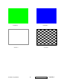
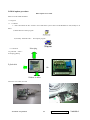
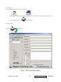
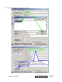
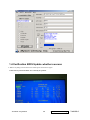
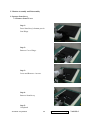
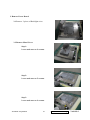
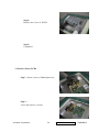
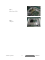
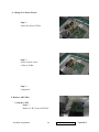
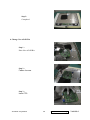
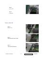
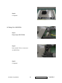
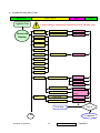
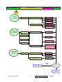
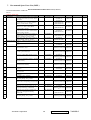
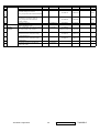
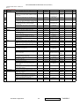
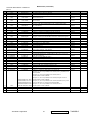
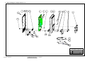
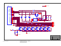
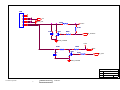
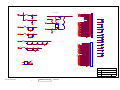
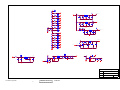
1
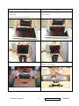
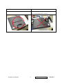
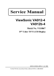
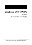
Service Manual
ViewSonic VA912/b-3
Model No. VS10931
19” Color TFT LCD Display
( VA912/b- 3_SM Rev. 1a Oct. 2005)
ViewSonic 381 Brea Canyon Road, Walnut, California 91789 USA - (800) 888-8583
Copyright
Copyright © 2005 by ViewSonic Corporation. All rights reserved. No part of this publication may be
reproduced, transmitted, transcribed, stored in a retrieval system, or translated into any language or
computer language, in any form or by any m eans, electronic, mechanical, magnetic, optical, chemical,
manual or otherwise, without the prior written permission of ViewSonic Corporation.
Disclaimer
ViewSonic makes no representations or warranties, either expressed or implied, with respect to the
contents hereof and specifically disclaims any warranty of merchantability or fitness for any particular
purpose. Further, ViewSonic reserves the right to revise this publication and to make changes from
time to time in the contents hereof without obligation of ViewSonic to notify any person of such revision
or changes.
Trademarks
Optiquest is a registered trademark of ViewSonic Corporation.
ViewSonic is a registered trademark of ViewSonic Corporation.
All other trademarks used within this document are the property of their respective owners.
Revision History
Revision
1a
SM Editing Date ECR Number
10/12/05
Description of Changes
Initial Release
ViewSonic Corporation
Editor
G. Han
Confidential-Do Not Copy VA912/b-3
I
1. Precautions and Safety Notices
1
2. Specification
5
3. Front Panel Function Control Description
10
4. Circuit Description
16
5. Adjustment Procedure
18
6. Troubleshooting Flow Chart
42
7. Recommended Spare Parts List
48
8. Exploded Diagram and Exploded Parts List
53
9. Block Diagram
55
10. Schematic Diagrams
56
11. PCB Layout Diagrams
69
ViewSonic Corporation
Confidential-Do Not Copy VA912/b-3
II
1. Precautions and Safety Notices
1. Appropriate Operation
(1) Turn off the product before cleaning.
(2) Use only a dry soft cloth when cleaning the LCD panel surface.
(3) Use a soft cloth soaked with mild detergent to clean the display housing.
(4) Use only a high quality, safety approved AC/DC power cord.
(5) Disconnect the power plug from the AC outlet if the product will not be used for a long period of time.
(6) If smoke, abnormal noise, or strange odor is present, immediately switch the LCD display off.
(7) Do not touch the LCD panel surface with sharp or hard objects.
(8) Do not place heavy objects on the LCD display, video cable, or power cord.
(9) Do not use abrasive cleaners, waxes or solvents for your cleaning.
(10) Do not operate the product under the following conditions:
- Extremely hot, cold or humid environment.
- Areas containing excessive dust and dirt.
- Near any appliance generating a strong magnetic field.
- In direct sunlight.
2. Caution
No modification of any circuit should be attempted. Service work should only be performed after you are thoroughly
familiar with all of the following safety checks and servicing guidelines.
3. Safety Check
Care should be taken while servicing this LCD display. Because of the high voltage used in the inverter circuit, the
voltage is exposed in such areas as the associated transformer circuits.
4. LCD Module Handling Precautions
4.1 Handling Precautions
(1) Since front polarizer is easily damaged, pay attention not to scratch it.
(2) Be sure to turn off power supply when connecting or disconnecting input connector.
(3) Wipe off water drops immediately. Long contact with water may cause discoloration or spots.
(4) When the panel surface is soiled, wipe it with absorbent cotton or other soft cloth.
(5) Since the panel is made of glass, it may break or crack if dropped or bumped on hard surface.
(6) Since CMOS LSI is used in this module, take care of static electricity and ensure human earth when handling.
(7) Do not open or modify the Module Assembly.
(8) Do not press the reflector sheet at the back of the module in any direction.
(9) In the event that a Module must be put back into the packing container slot after it was taken out of the
container, do not press the center of the CCFL Reflector edge. Instead, press at the far ends of the
CFL Reflector edge softly. Otherwise the TFT Module may be damaged.
(10) At the insertion or removal of the Signal Interface Connector, be sure not to rotate or tilt the Interface
Connector of the TFT Module.
(11) After installation of the TFT Module into an enclosure (LCD monitor housing, for example), do not twist or
ViewSonic Corporation
1
Confidential-Do Not Copy
VA912/b-3
bend the TFT Module even momentarily. When designing the enclosure, it should be taken into consideration
that no bending/twisting forces may be applied to the TFT Module from outside. Otherwise the TFT Module
may be damaged.
(12) The cold cathode fluorescent lamp in the LCD contains a small amount of mercury. Please follow local
ordinances or regulations for disposal.
(13) The LCD module contains a small amount of materials having no flammability grade. The LCD module
should be supplied with power that complies with the requirements of Limited Power Source
(IEC60950 or UL1950), or an exemption should be applied for.
(14) The LCD module is designed so that the CCFL in it is supplied by a Limited Current Circuit (IEC60950
or UL1950). Do not connect the CCFL to a Hazardous Voltage Circuit.
ViewSonic Corporation
2
Confidential-Do Not Copy
VA912/b-3
Correct methods :
Incorrect Methods :
Only touch the metal-frame of the panel or the front cover
Surface of the panel is pressed by fingers & this may
of the monitor.
cause “ MURA “
Do not touch the surface of the polarizer .
Take out the monitor with cushion
Take out the monitor by grasping the LCD panel.
That may cause “ MURA“.
ViewSonic Corporation
3
Confidential-Do Not Copy
VA912/b-3
Correct Methods :
Incorrect Methods :
Place the monitor on a clean & soft foam pad .
Place the monitor on foreign objects .
That could scratch the surface of panel
ViewSonic Corporation
4
Confidential-Do Not Copy
VA912/b-3
2. Specification
2-1General Specifications
Test Resolution & Frequency
1280x1024 @ 60Hz
Test Image Size
Full Size
Factory Default:
Contrast and Brightness Controls
Contrast = 70%, Brightness = 100%
2.2 VIDEO INTERFACE
Analog Input Connector
DB-15 (Analog), refer the appendix A
Digital Input Connector
DVI-D 24pin, refer the appendix B
Default Input Connector
Defaults to the first detected input
Video Cable Strain Relief
Equal to twice the weight of the monitor for five minutes
Video Cable Connector DB-15 Pin out
Compliant DDC 2B
Video Signals
1.
Video RGB (Analog)
2.
DVI (Digital)
Separate
Video Impedance
75 Ohms (Analog)
Maximum PC Video Signal
950 mV with no damage to monitor
Maximum Mac Video Signal
1250 mV with no damage to monitor
Sync Signals
TTL
DDC 2B
Compliant with Revision 1.3
Sync Compatibility
Separate Sync
Shall be compatible with all PC type computers,
Video Compatibility
Macintosh computers, and after market video cards
640 x 350*, 640 x 480, 720 x 400* (640 x 400*), 800 x
600, 832 x 624, 1024 x 768, 1152 x 870, 1280 x 720,
1280 x 960, 1280 x 1024
Resolution Compatibility
* The image vertical size might not be full screen.
But the image vertical position should be at the center.
Exclusions
ViewSonic Corporation
Not compatible with interlaced video
5
Confidential-Do Not Copy
VA912/b-3
2-3
POWER SUPPLY
Power Supply (Adapter)
Part Number: 27-D003115
Input Voltage Range
100 TO 240 VAC
Input Frequency Range
50 TO 60 HERTZ
Short Circuit Protection
Output can be shorted without damage
Over Current Protection
3.3~4.5 A typical at 5 VDC
Leakage Current
3.5 mA (Max) at 254VAC / 60Hz
EFFICIENCY
80 % typical at 115 VAC Full Load
Fuse
Internal and not user replaceable
Power Dissipation
58 (Max) Watt
Max Input AC Current
1.8 A rms @ 100 VAC,
INRUSH CURRENT (COLD START)
120A(max) @ 240VAC , 50Hz
Shall start and function properly when under full load,
Power Supply Cold Start
with all combinations of input voltage, input frequency,
and operating temperature
Shall be able to withstand an EN61000-4-4 ± 2KV
Power Supply Transient Immunity
transient test with no damage
Shall be able to withstand ±2KV (L-L) and ± 2.3KV
Power Supply Line Surge Immunity
(L-PE) with no damage
Shall be able to function properly, without reset or visible
Power Supply Missing Cycle Immunity
screen artifacts, when ½ cycle of AC power is randomly
missing at nominal input
The power supply shall not produce audible noise that
would be detectable by the user. Audible shall defined
Power Supply Acoustics
to be in compliance with ISO 7779 (DIN EN27779:1991)
Noise measurements of machines acoustics. Power
Switch noise shall not be considered
Separate 3-prong NEMA 5-15P type plug. Length =
US Type Power Cable
1.8m. Connects to display.
Color = Black
Schuko CEE7-7 type plug.
European Type Power Cable
Length = 1.8m, Connects to display.
Color = Black
Separate 3-prong type plug.
CCC Type Power Cable
Length = 1.8m. Connects to display.
Color = Black
Power Saving Operation(Method)
VESA DPMS Signaling
Power Consumption
ON Mode < 58 W (max)
ViewSonic Corporation
6
Confidential-Do Not Copy
VA912/b-3
ACTIVE OFF < 2 W
Recovery Time
2-4
ON MODE = N/A, ACTIVE OFF < 3 SEC
ELECTRICAL REQUIREMENT
Horizontal / Vertical Frequency
Horizontal Frequency
30 – 82 KHZ
Vertical Refresh Rate
50 – 85* HZ.
Maximum Pixel Clock
135 MHz (EDID file is 140MHz)
Sync Polarity
Independent of sync polarity.
Timing Table
Item
Timing
Analog
Digital
1
640 x 350 @ 70Hz, 31.5kHz
Yes
Yes
2
640 x 400 @ 60Hz, 31.5kHz
Yes*
Yes
3
640 x 400 @ 70Hz, 31.5kHz
Yes
Yes
4
640 x 480 @ 60Hz, 31.5kHz
Yes
Yes
5
640 x 480 @ 67Hz, 35.0kHz
Yes
Yes
6
640 x 480 @ 72Hz, 37.9kHz
Yes
Yes
7
640 x 480 @ 75Hz, 37.5kHz
Yes
Yes
8
640 x 480 @ 85Hz, 43.27kHz
Yes
Yes
9
720 x 400 @ 70Hz, 31.5kHz
Yes
Yes
10
800 x 600 @ 56Hz, 35.1kHz
Yes
Yes
11
800 x 600 @ 60Hz, 37.9kHz
Yes
Yes
12
800 x 600 @ 75Hz, 46.9kHz
Yes
Yes
13
800 x 600 @ 72Hz, 48.1kHz
Yes
Yes
14
800 x 600 @ 85Hz, 53.7kHz
Yes
Yes
15
832 x 624 @ 75Hz, 49.7kHz
Yes
Yes
16
1024 x 768 @ 60Hz, 48.4kHz
Yes
Yes
17
1024 x 768 @ 70Hz, 56.5kHz
Yes
Yes
18
1024 x 768 @ 72Hz, 58.1kHz
Yes
Yes
19
1024 x 768 @ 75Hz, 60.0kHz
Yes
Yes
20
1024 x 768 @ 85Hz, 68.67kHz
Yes
Yes
21
1152 x 870 @ 75Hz, 68.7kHz
Yes
Yes
22
1280 x 1024 @ 60Hz, 63.4kHz
Yes
Yes
23
1280 x 1024 @ 75Hz, 79.97kHz
Yes
No
24
1280x 720 @ 60Hz, 45kHz (HDTV)
Yes
Yes
Note 1:When Vertical frequency at 85Hz or resolution, the vertical image size might not be full screen. But the
ViewSonic Corporation
7
Confidential-Do Not Copy
VA912/b-3
vertical image position should be at the center.
Note2: *: The vertical image size might not be full screen.
2-5
AUDIO INTERFACE (SPEAKER SPECIFICATION)
Line input connection
3.5 mm stereo jack
Line input signal
1.0Vrms@1kHz
Line input impedance
10k ohm
Maximum power output (Electric)
2W
Signal to Noise Ratio
72db
Frequency response
F0 -20kHz (F0 : Lowest resonant freq.)
Distortion
<8% THD @1kHz
There should be no audible vibration with volume at
Vibration
100%. (Input signal within 1 Vrms)
There should be no affect on the screen image
Screen image
stability under any conditions
Connector PC99 requirement Audio in
Lime Green pantone # 577C
Cable type / length
3.5mm stereo cable / 1.8m length
Note: There is no guarantee <1 W power
Audio DPMS
consumption in Active Off mode, when the Audio
Cable is connected
2-6
TFT LCD PANEL
Panel Source Identify
(1) ID label - The panel code “B” for CMO panel should be shown on the lower right side of ID label. (See
Figure 2)
(2) UPC label - The panel code “B” for CMO panel should be shown on the lower right side of UPC label. (See
Figure 3)
ViewSonic Corporation
8
Confidential-Do Not Copy
VA912/b-3
Panel Characteristics:
Model number
A190E3
Type
TN type with RSDS interface
Active Size
376.32 (H) x 301.056 (V)
Pixel Arrangement
RGB Vertical Stripe
Pixel Pitch
0.294 mm
GLASS TREATMENT
Anti Glare (Hard coating 3H)
# OF BACKLIGHTS
4 CCFL (L type); Edge Light BLU
BACKLIGHT LIFE
50,000 Hours (min)
Luminance (Center) –
280 cd/m2 (Typ after 15 minute warm up)
Condition:
180 cd/m2 (M in after 15 minute warm up)
CT = 6500K, Contrast = Max, Brightness = Max
U = 76% (typ), 67% (M in).
Brightness Uniformity (13 Points)
U = Min Luminance in 13 points / Ma x Luminance in 13
points
Contrast Ratio
450 (typ), 250 (min)
Color Depth
16 million colors (6 bit + 2 bit FRC)
@ CR>10
Viewing Angle (Horizontal)
Typical:
Minimum:
@ CR>5
150
130
@ CR>10
VIEWING ANGLE (VERTICAL)
Typical:
Typical:
Minimum:
130
Typical:
TBD
Minimum:
TBD
Response Time
8ms (Tr= 2 ms, Tf = 6 ms) (typ)
10% -90% @ Ta=25°C
18 ms (Tr= 7 ms, Tf = 11 ms) (max)
Panel Defects
Please see Panel Quality Specifications.
9
TBD
@ CR>5
Minimum: 110
ViewSonic Corporation
TBD
Confidential-Do Not Copy
VA912/b-3
3. Front Panel Function Control Description
Adjusting the Screen Image
Use the buttons on the front control panel to display and adjust the OSD controls which display
on the screen. The OSD controls are explained at the top of the next page and are defined in
“Main Menu Controls” on page 10.
Main Menu
with OSD controls
Front Control Panel
shown below in detail
Scrolls through menu options and
adjusts the displayed control.
Also a shortcut to display the Contrast
adjustment control screen.
Displays the Main Menu or
exits the control screen and
saves adjustments.
Displays the control screen
for the highlighted control.
Also toggles between two
controls on some screens.
Also a shortcut to toggle
analog and digital connection.
Power light
Green = ON
Orange = Power Saving
Audio Mute
button turns
the sound off
Standby Power
On/Off
ViewSonic Corporation
10
Confidential - Do Not Copy
VA912/b-3
Do the following to adjust the display setting:
1. To display the Main Menu, press button [1].
NOTE: All OSD menus and adjustment screens disappear automatically after about 15
seconds. This is adjustable through the OSD timeout setting in the setup menu.
2. To select a control to adjust, pressSorTto scroll up or down in the Main Menu.
3. After the desired control is selected, press button [2]. A control screen like the one shown
below appears.
The command line at the bottom of the
control screen tells what to do next from
this screen. You can toggle between control
screens, adjust the selected option, or exit
the screen.
4. To adjust the setting, press the up S or down T buttons.
5. To save the adjustments and exit the menu, press button [1] twice.
The following tips may help you optimize your display:
• Adjust the computer's graphics card so that it outputs a 1280 x 1024 @ 60Hz video signal to
the LCD display. (Look for instructions on “changing the refresh rate” in the graphics card's
user guide.)
• If necessary, make small adjustments using H. POSITION and V. POSITION until the
screen image is completely visible. (The black border around the edge of the screen should
barely touch the illuminated “active area” of the LCD display.)
ViewSonic Corporation
11
Confidential-Do Not Copy
VA912/b-3
Main Menu Controls
Adjust the menu items shown below by using the up S and down T buttons.
Control
Explanation
Auto Image Adjust sizes and centers the screen image automatically.
Contrast adjusts the difference between the image background (black level)
and the foreground (white level).
Brightness adjusts background black level of the screen image.
Input Select toggles between inputs if you have more than one computer
connected to the VA912/VA912b.
Audio Adjust
Volume increases the volume, decreases the volume, and mutes the audio.
Mute temporarily silences audio output.
Color Adjust provides several color adjustment modes, including preset color
temperatures and a User Color mode which allows independent adjustment of
red (R), green (G), and blue (B). The factory setting for this product is 6500K
(6500 Kelvin).
9300K-Adds blue to the screen image for cooler white (used in most office
settings with fluorescent lighting).
6500K-Adds red to the screen image for warmer white and richer red.
5400K-Adds green to the screen image for a darker color.
ViewSonic Corporation
12
Confidential - Do Not Copy
VA912/b-3
Control
Explanation
5000K-Adds blue and green to the screen image for a darker color.
User Color Individual adjustments for red (R), green (G), and blue (B).
1. To select color (R, G or B) press button [2].
2. To adjust selected color, pressSandT.
Important: If you select RECALL from the Main Menu when the product is
set to a Preset Timing Mode, colors return to the 6500K factory preset.
Information displays the timing mode (video signal input) coming from the
graphics card in the computer, the LCD model number, the serial number, and
the ViewSonic® website URL. See your graphics card’s user guide for
instructions on changing the resolution and refresh rate (vertical frequency).
NOTE: VESA 1280 x 1024 @ 60Hz (recommended) means that the resolution
is 1280 x 1024 and the refresh rate is 60 Hertz.
Manual Image Adjust Sub-menu
H. Size (Horizontal Size) adjusts the width of the screen image.
H./V. Position (Horizontal/Vertical Position) moves the screen image left or
right and up or down.
ViewSonic Corporation
13
Confidential-Do Not Copy
VA912/b-3
Control
Explanation
Fine Tune sharpens the focus by aligning text and/or graphics with pixel
boundaries.
NOTE: Try Auto Image Adjust first.
Sharpness adjusts the clarity and focus of the screen image.
Setup Menu displays the menu shown below:
Language Select allows the user to choose the language used in the menus and
control screens.
Resolution Notice allows the user to enable or disable this notice.
If you enable the Resolution Notice shown above and your computer is set at a
resolution other than 1280 x 1024, the following screen appears.
OSD Position allows the user to move the OSD menus and control screens.
OSD Timeout sets the length of time the OSD screen is displayed. For example,
with a “30 second” setting, if a control is not pushed within 30 seconds, the
display screen disappears.
ViewSonic Corporation
14
Confidential - Do Not Copy
VA912/b-3
Control
Explanation
OSD Background allows the user to turn the OSD background On or Off.
Memory Recall returns the adjustments back to factory settings if the display is
operating in a factory Preset Timing Mode listed in the Specifications of this
manual.
ViewSonic Corporation
15
Confidential-Do Not Copy
VA912/b-3
4. Circuit Description
Circuit Description
1. Power supply (DC/DC Converter)
The AAT1109 is a one-channel step-up PWM controller incorporating a soft-start and a short circuit protection
(SCP) function. This device consists of an on-chip voltage reference, error amplifier, pulse width modulation
controller, under-voltage lockout protection, soft-start, and
short circuit protection circuits.
ViewSonic Corporation
16
Confidential - Do Not Copy
VA912/b-3
2. Micro Controller
The MTV312M micro-controller is an 8051 CPU core embedded device especially tailored for CRT/LCD Monitor
applications. It includes an 8051 CPU core, 1024-byte SRAM, 14 built-in PWM DACs , VESA DCC interface,
4-channel A/D converter , and a 64K-byte internal program FLASH-ROM.
3. TSU57AK
The TSU57AK is a high performance, and fully integrated graphics process IC solution for LCD monitors with
resolution up to SXGA. It is configured with an integrated triple-ADC/PLL, a high quality scaling engine, an
on-screen display controller, a built-in output clock generator, a panel timing controller (TCON), an integrated DVI
receiver, and RSDS display interface. To further reduce system costs, the TSU57AK also integrates intelligent power
management control capability for green-mode requirements and spread-spectrum support for EMI management.
ViewSonic Corporation
17
Confidential-Do Not Copy
VA912/b-3
5. Adjusting Procedure
A. Function Test and Alignment Procedure
5.1 All Modes Reset
You should do “All Model Reset” (Refer to Chap 3. Hot Keys for Function Controls) first. This action will allow
you to erase all end-user’s settings and restore the factory defaults.
5.2 Auto Image Adjust
The Auto Adjust is aimed to offer a best screen quality by built-in ASIC. For optimum screen quality, the user
has to adjust each function manually.
A.Turn the computer and LCD monitor on.
B. Press the ‘Auto’ button on monitor keypad to Auto Adjust.
C. The LCD monitor will start the Auto Adjust process automatically and run for 10 consecutive seconds, during
which time you will notice the image change.
5.3 Firmware
Test Patten : Burn in Model (Refer to Chap3. Hot Keys for Function Control)
-Make sure the F/W is the latest version.
5.4 DCC
Test Patten: EDID program
-Make sure it can pass test program.
5.5 Window Shut Down
Test Signal: 1280*1024@60Hz
Test Pattern:
Checkered Pattern Every One Pixel (50%Green & 50%Blue)
Inspection Item: Flicker, Mura
5.6 Window BG
Test Signal: 1280*1024@60Hz
Test Pattern:
Window standard pattern
Inspection Item: Line Defect, Function Defect & Mura
ViewSonic Corporation
18
Confidential-Do Not Copy
VA912/b-3
5.7 25 Gray
Test Signal: 1280*1024@60Hz
Test Pattern:
Full Screen 25% White (Gray)
Inspection Item: Particle, Line Defect & Mura
5.8 50 Gray
Test Signal: 1280*1024@60Hz
Test Pattern:
Full Screen 50% White (Gray)
Inspection Item: Bright Dot, Particle, Line Defect & Mura
5.9 White Box
Test Signal: 1280*1024@60Hz
Test Pattern:
Window standard pattern
Inspection Item: Particle, Line Defect, Power, Image Remain & Mura
5.10 Black Box
Test Signal: 1280*1024@60Hz
Test Pattern:
Window standard pattern
Inspection Item: Bright Dot, Line Defect & Power
ViewSonic Corporation
19
Confidential-Do Not Copy
VA912/b-3
5.11 RED
Test Signal: 1280*1024@60Hz
Test Pattern:
Full Screen Red
Inspection Item: Bright Dot, Partial & Line Defect
5.12 Green
Test Signal: 1280*1024@60Hz
Test Pattern:
Full Screen Green
Inspection Item: Bright Dot, Partial & Line Defect
5.13 Blue
Test Signal: 1280*1024@60Hz
Test Pattern:
Full Screen Green
Inspection Item: Bright Dot, Partial & Line Defect
5.14 Gray_Scale_0-100_V256
Test Signal: 1280*1024@60Hz
Test Pattern:
Vertical 64 (256) Gray Scale (Right → Left,From 0 to 100% White)
Inspection Item: Line Defect & Function Defect
ViewSonic Corporation
20
Confidential-Do Not Copy
VA912/b-3
5.15 Gray_Scale_0-100_H256
Test Signal: 1280*1024@60Hz
Test Pattern:
Horizontal 64(256) Gray Scale (Up → Down,From 0 to 100% White)
Inspection Item: Line Defect & Function Defect
5.16 Block Window
Test Signal: 1280*1024@60Hz
Test Pattern:
Black block at the center
Inspection Item: Cross Talk & Optical Character
5.17 Black_Tile
Test Signal: 1280*1024@60Hz
Test Pattern:
Black tile under white background
Inspection Item: Function Defect & Image Remain
ViewSonic Corporation
21
Confidential-Do Not Copy
VA912/b-3
5-18. Function Test Display pattern
Item
Pattern
1
Gray_Scale_0-100_V
Description
Remark
Vertical 64 (256) Gray Scale (右→左,From 0 to
Figure 1
100% White)
Horizontal 64 (256) Gray Scale (上→下,From 0
2
Gray_Scale_0-100_H
Figure 2
to 100% White)
3
Black
Full Screen Black
Figure 3
4
Red
Full Screen 50% Red
Figure 4
5
Green
Full Screen 50% Green
Figure 5
6
Blue
Full Screen 50% Blue
Figure6
7
White
Full Screen White
Figure7
8
Black_Tile
Black Tile Under White Background
Figure 8
FIGURE 1
FIGURE 2
Figure 3
ViewSonic Corporation
Figure 4
22
Confidential-Do Not Copy
VA912/b-3
Figure 5
FIGURE 5
FIGURE 6
FIGURE 7
ViewSonic Corporation
FIGURE 8
23
Confidential-Do Not Copy
VA912/b-3
B. BIOS update procedure
BIOS Update User Guide
BIOS U FLOW FOR GENESIS
1.1 Program:
1. 1. 1. Software
a. Please download the file “ M-Star” from CMO E-Sir system. There are ISP & BIOS two files, kindly see as
below.
a) ISPACK.EXE: Main program
b) Ancillary .ISPACK.EXE :Description program
1.1. 2.Hardwar
Point plug
•D_Sub cable (15Pin)
•Point plug [24Pin]
D_Sub cable
OR
Without to affect
1.1.3 Join VGA Cable, PC BASE, see the example picture as below.
ViewSonic Corporation
24
Confidential-Do Not Copy
VA912/b-3
1.2 Installation:
A. Please install the programs respectively as below.
B. ISP & BIOS software file to be about to produce the next. (If the file existence already, needn’t to set up.
C. repeat.) This system is applied to Win 95/98/NT/2000.
Isp.lnk
1.3 ISP Execution
1. Settings:
Double Click
Isp.lnk
Fig.1: ISP Tool Main Menu
ViewSonic Corporation
25
Confidential-Do Not Copy
VA912/b-3
2. When ISP Tool executing at the first time, it is required to enter Security
Data Please press
, then input related information as Fig.2.
4C
7C 4C 77
For A190E3
Key in “OK”
3. Select correct Micro Controller as Fig.3.
Step 2
Load MCU File
Step 1
Select MTV312M64
ViewSonic Corporation
26
Confidential-Do Not Copy
VA912/b-3
4. Installation software, Select
want download
correct file
Step 3 Example :
The path of software
Step 4
Press RUN
ViewSonic Corporation
27
Confidential-Do Not Copy
VA912/b-3
1.4.Verification BIOS Update whether success
5. When everything is done. Please turn off the power and restart it again.
Check Factory Mode and make sure it already be updated.
ViewSonic Corporation
28
Confidential-Do Not Copy
VA912/b-3
C. Monitor Assembly and Disassembly
1. Separate Stand Assy
1.1 Remove Stand Cover
Step 1 :
Press Stand Assy’s bottom part in
Seat Hinge.
Step 2 :
Remove Cover Hinge.
Step 3 :
Loose and Remove 4 screws.
Step 4:
Remove Stand Assy.
Step 5:
Completed
ViewSonic Corporation
29
Confidential-Do Not Copy
VA912/b-3
2. Separate Rear Cover (Rear Case Assy)
Loosen and remove 5 screws.
Separate Bezel hooks to take Bezel and Rear Cover apart.
Step 1 :
Loose and remove 2 screws.
Step 2 :
Separate Bezel hooks to take
Bezel and Rear Cover apart.
Step 3 :
Remove Rear Cover.
Step 4 :
Completed
ViewSonic Corporation
30
Confidential-Do Not Copy
VA912/b-3
3. Remove Power Board
3.1 Remove 2 pieces of Backlight wires.
3.2 Remove Metal Cover
Step 1 :
Loose and remove 4 screws.
Step 2 :
Loose and remove 2 screws.
Step 3 :
Loose and remove 4 screws.
ViewSonic Corporation
31
Confidential-Do Not Copy
VA912/b-3
Step 4 :
Remove the Cover of X-PCB.
Step 5 :
Completed
3.3 Remove Power PCBA
Step 1 : Insert 2 pieces of Backlight wires.
Step 2 :
Loose and remove 4 screws.
ViewSonic Corporation
32
Confidential-Do Not Copy
VA912/b-3
Step 3 :
Remove Power PCBA.
Step 4 :
Completed
ViewSonic Corporation
33
Confidential-Do Not Copy
VA912/b-3
4. Change New Power Board
Step 1 :
Insert New Power PCBA.
Step 2 :
Fasten 4 fixed screws
of Power PCBA .
Step 3 :
Completed
5. Remove AD PCBA
5.1 Remove FFC
Step 1 :
Remove 2 FFC from AD PCBA.
ViewSonic Corporation
34
Confidential-Do Not Copy
VA912/b-3
Step 2 :
Remove FFC
5.2 Remove AD PCBA
Step 1 :
Loose and remove 4 screw
Step 2 :
Remove AD PCBA.
ViewSonic Corporation
35
Confidential-Do Not Copy
VA912/b-3
Step 3 :
Completed
6. Change New AD PCBA
Step 1 :
Place New AD PCBA.
Step 2 :
Fasten 4 screw.
Step 3 :
Insert FFC.
ViewSonic Corporation
36
Confidential-Do Not Copy
VA912/b-3
Step 4 :
Insert 2 FFC.
Step 5 :
Completed
7 Remove OSD PCBA
Step 1 :
Remove FFC.
Step 2 :
Separate both Audio Cable.
Step 3 :
Take OSD PCBA apart.
ViewSonic Corporation
37
Confidential-Do Not Copy
VA912/b-3
Step 4 :
Completed.
8. Change New OSD PCBA
Step 1 :
Place New OSD PCBA.
Step 2 :
Insert Audit Cable to connectors
of OSD PCBA.
Step 3 :
Completed.
ViewSonic Corporation
38
Confidential-Do Not Copy
VA912/b-3
9. Add Cover to AD PCB Heatsink
Step 1 :
Join the cover hooks of X-PCB.
Step 2 :
Fasten the 4 screws.
Step 3 :
Fasten 2 screws.
Step 4 :
Fasten the 4 screws.
Step 5 :
Completed
ViewSonic Corporation
39
Confidential-Do Not Copy
VA912/b-3
10. Rear Assy Assembly
Step 1 :
Place Rear Cover.
Step 2 :
Join Rear Cover with Bezel.
Step 3 :
Fasten 2 screws.
Step 4 :
Completed
ViewSonic Corporation
40
Confidential-Do Not Copy
VA912/b-3
11. Stand Assy Assembly
Step 1 :
Place Stand Assy .
Step 5 :
Fasten 4 screws to fixed Stand Assy.
Step 6 :
Insert Cover Hinge.
Step 7 :
Place Stand Assy.
ViewSonic Corporation
41
Confidential-Do Not Copy
VA912/b-3
6. Trouble Shooting Flow Chart
Defect Mode
Failure Analysis
Light On Test
Repair
Testing
※ Panel Change” Should be Performed to Level 3 Repair stage
Missing Line
Abnormal
Display
Check PCB
AD/B Change
Check Panel
Panel Change
Check Panel
Panel Change
Bright Dot
Dark Dot
Backlight
Light Leakage
Mura
Image Sticking
Brightness spot
Particle
Dot Defect
No display
Check PCB
AD/B Change
P/B Change
CNT/B Change
Check Panel
Panel Change
Check Wire
D-sub cable
change
Noise
Check PCB
AD/B Change
Check Panel
Panel Change
N
Next Step
A
ViewSonic Corporation
TEST
Completed
42
Confidential-Do Not Copy
VA912/b-3
Defect Mode
Failure Analysis
A
Repair
Testing
“ Panel Chan
e” Should be Performed to Level 3 Repair stage
Check PCB
Flicker
AD/B Change
P/B Change
Gray value
display
R.G.B display
Check Panel
Panel Change
Check PCB
AD/B Change
Check Panel
Panel Change
Check PCB
AD/B Change
abnormal
CNT/B Change
Check Panel
Check Wire
Display Shut
Check PCB
Down
Panel Change
D-sub cable
change
AD/B Change
P/B Change
No signal
Check Panel
Panel Change
Check PCB
AD/B Change
CNT/B Change
Check Wire
Power on
Display
abnormal
D-sub cable change
Check PCB
AD/B Change
Check Panel
Panel Change
Next Step
NG
TEST
Completed
ViewSonic Corporation
43
Confidential-Do Not Copy
VA912/b-3
Defect Mode
Failure Analysis
Repair
Testing
※ “ Panel Change” Should be Performed to Level 3 Repair stage
ON/OF
No Power
Check PCB
AD/B Change
Abnormal
P/B Change
CNT/B Change
Check Wire
PW cable Change
OSD cable Change
LED display
abnormal
Check PCB
LED Off
AD/B Change
LED Dark
P/B Change
LED Abnormal
OSD cable Change
LED Flicker
Check Wire
Power wire connector
Cable change
Abnormal
Keyboard
Check PCB
Unavailable
AD/B Change
P/B Change
Check Wire
OSD cable Change
NG
TEST
Next Step
Completed
ViewSonic Corporation
44
Confidential-Do Not Copy
VA912/b-3
Defect Mode
Failure Analysis
Repair
Testing
※ “ Panel Change” Should be Performed to Level 3 Repair stage
Abnormal BIOS
Can’t Input
Check PCB
&OSD
AD/B Change
CNT/B Change
Check Wire
Can’t Reader
Other Abnormal
Display
Display Shut
Check PCB
Down
D-sub cable change
AD/B Change
P/B Change
CNT/B Change
Display flicker
Check Panel
Panel Change
Check PCB
AD/B Change
(tapping )
CNT/B Change
Check Panel
Next Step
P/B Change
NG
TEST
Completed
ViewSonic Corporation
45
Confidential-Do Not Copy
VA912/b-3
u
Trouble Shooting Analysis
Check the information in this section to see if the problems can be solved before requesting repair.
Note:The consumers are only allowed to solve the problems described as below. Any unauthorized
product modification, or failure to follow instructions supplied with the product will end the warranty
immediately.
l
No image
u
Make sure power button is ON.
u
Check whether the LCD monitor and computer power cords are plugged and whether there is a
supply of power.
l
No Signal Input
u
l
Check the signal connection between the computer and LCD monitor.
“Out of Range”
u
Check the computer image output resolution and frequency and compare the value with the
preset values (Please refer to [Appendix-Display Mode]).
l
Fuzzy Image
u
l
Image too bright
u
l
l
l
l
Adjust brightness and contrast by OSD.
Image too dark
u
l
Adjust Phase.
Adjust brightness and contrast by OSD.
Irregular image
u
Check the signal connection between the computer and LCD monitor.
u
Perform Auto Adjust.
Distorted image
u
Reset the LCD monitor
u
Take off e xtra accessories (such as signal extension cord).
Image is not centered
u
Use OSD Image Menu to adjust H_Position and V_Position.
u
Check image size setting.
u
Perform Auto Adjust.
Size is not appropriate
ViewSonic Corporation
46
Confidential-Do Not Copy
VA912/b-3
l
u
Use OSD Image Menu to adjust H_Position and V_Position.
u
Check image size setting.
u
Perform Auto Adjust.
u
Use OSD Color Menu to adjust color setting.
Color too dark
u
l
Dark area distorted
u
l
Use OSD Color Menu to adjust color setting.
Use OSD Color Menu to adjust color setting.
White color is not white
u
Use OSD Color Menu to adjust color setting.
ViewSonic Corporation
47
Confidential-Do Not Copy
VA912/b-3
7.
Recommend Spare Parts List (RSPL)
RECOMMENDED SPARE PARTS LIST (VA912-3)
ViewSonic Model Number: VS10931-1W
Rev: 1a
Serial No. Prefix: PUQ
Description
Ref. P/N
Item
ECR/ECN ViewSonic P/N
Location Universal number#
Adapter, Lips Without Audio, DAC-19M001
A-00004021
Accessories:
27-D003115
27-D003115
BF, Ver:00 A, 19 V/2.5 A, 5 V/3 A, 4L, 4.9
1
mA, 2380 V
32E1818018
A-00002059
Power Code, CEE, SP-023+IS-14, H05VV-F,
32E1818018
(AJ0E3H1E1F/2F)
3G, 0.75mm2, CT-12, L=1800+/-50mm, I2
(AJ0E3H1K1F/2F)
SHENG, 18AWG, Black, No Bag
Power Code, UL, SVT#18/3C, 75℃, LPA-00000458
32E1818015
32E1818015
30B+LS-13, L=1830+/-50mm, Black,
(AJ0E3H1A1F/2F)
3
Linetek, 18AWG, No Bag
A-00002058
Power Cord CCC, 300/500V, 0.75mm2, 3C,
32E1818013
32E1818013
PC-323+COC-01, L=1830+/-50mm, Black,
(AJ0E3H1C1F/2F)
4
Linetek, 18AWG, No Bag
A-00002057
Power Cord, BSI, H05VV-F, 0.75mm2, 3C,
32E1818060
32E1818060
LP-60L+LS-60, L=1830+/-50mm, Black,
(AJ0E3H1K1F/2F)
5
18AWG, PSB Mark, Linetek, No Bag
32-D001922
Power Cord, VCTF 3G 0.75mm^2 CNS CTA-00004047
32-D001922
6
(AJ0E3H1W1F/2F)
08, Black, BSMI, 1800 mm, I Sheng
B-00004022
Board Assembly: PCBA for , A190E3, A190E3-H-S1, 301-72,
35-D004062
35-D004062
7
Rev.07
B-00004023
PCBA for , A190E3, A190E3-T-K, 303-02,
35-D002998
35-D002998
8
Rev.31
40-D003819
Bezel Assy, A190E3-H0F, SILVER
C-00004025
(AJ0E3H1A.C.E.K.W2F 40-D003819
PANTONE 877C, Injex
9
)
40-D003812
Cover Hinge, A190E3-H0F, ABS PA-757N,
C-00004026
(AJ0E3H1A.C.E.K.W2F 40-D003812
BLACK C_J91A11B5, Injex
10
)
40-D003818
Rear Assy, A190E3-H0F, BLACK C, Injex
C-00004028
(AJ0E3H1A.C.E.K.W2F 40-D003818
11
)
40-D003821
Seat Assy, A190E3-H0F, BLACK C, Hontech
C-00004030
(AJ0E3H1A.C.E.K.W2F 40-D003821
Precision Industry
12
)
40-D003820
Stand Assy, A190E3-H0F, BLACK C,
C-00004032
(AJ0E3H1A.C.E.K.W2F 40-D003820
Hontech Precision Industry
13
)
Audio Cable, A150X2, 18AWG, 180cm,
CB-00000544
Cables:
32F2818004
32F2818004
14
Black, JCE
FFC_X, 0.50x45x62xCx(5/5)x(0.175x0.3), 45
CB-00004034
32-D000557
32-D000557
15
Pins, no AL foil
Monitor Cable, A150X2, 30AWG, 180cm,
CB-00000547
32F3018003
32F3018003
16
Black, JCE
17
32-D003899
32-D003899
FFC-OSD, 22 Pins, TennRich
CB-00004035
77-D004154
DC-00004036
Documentation: Carton Label for , A190E3-H0F, 20 mmx20
77-D004154
18
mm, Chang Huang, VSC_VA912-3
77-D004123
Carton Label for , A190E3-H0F, 76.2
DC-00004037
(AJ0E3H1A.C.E.K.W2F 77-D004123
mmx76.2 mm, Chang Huang, VSC(VA912-3)
19
)
20
7741519181
7741519181
Label, Bar-Code Labe, 55*13mm
DC-00002073
76-D004095
MENU for VSC_VA912-3, Paper, 1C, YiDC-00004039
(AJ0E3H1C.E.K.W1F/2 76-D004095
Ching Special Printing, A190E3-H0F
21
F)
MENU for VSC_VA912-3+Caution Card,
DC-00004040
76-D004134
76-D004134
Paper, 1C, Yi-Ching Special Printing,
(AJ0E3H1A1F/2F)
22
A190E3-H0F
77-D004087
Safety Label for , A190E3-H0F, 120 mmx50
DC-00004041
(AJ0E3H1A.C.E.K.W2F 77-D004087
mm, Chang Huang, VSC_VA912-3
23
)
ViewSonic Corporation
48
Confidential-Do Not Copy
VA912/b-3
Q'ty
1
1
1
1
1
1
1
1
1
1
1
1
1
1
2
1
1
1
1
1
1
1
1
Item
24 Hardware:
25
Description
ECR/ECN ViewSonic P/N
Screw, M3*P0.5*4, f 5.5*2
HW-00000553
Screw, M3*P1.27*12, f 5.5*2
HW-00000556
SCREW, M4, P=0.7 mm, L=15 mm, Special
HW-00002442
Thin Head, Phillips Cross Recess,
Screw_with_Washer, SHYE CHING SCREW
Ref. P/N
42A9930008
42A9990005
Location Universal number#
42A9930008
42A9990005
Q'ty
2000
2000
42-D000314
42-D000314
2000
42-D000649
42-D000649
2000
42A9940007
42A9940007
2000
7345511002
7345511002
1
78-D004088
(AJ0E3H1A.C.E.K.W2F 78-D004088
)
1
26
27
28
Miscellaneous:
29
Packing
Material:
SCREW, M4, P=0.7 mm, L=8 mm, Round
Head, Phillips Cross Recess, plate Ni,
Screw_with_Washer, SHYE CHING
SCREW, head D8
Stand-Off 4 #-40*11.8
Tape, Security Tape, OPP,
L900xW50x0.045mm, VSC
Carton, A190E3-H0F, 536 mmx148 mmx475
mm, Chen Ti Paper, VSC_VA912-3
HW-00004042
M-00000559
M-00000560
P-00004043
30
31
32
33
34
P-00004045
Cushion, A190E3-H0F, PE_LD, White, 530
mmx140 mmx50 mm, N/A, Hwa Chang,
PE_Foam(BOTTOM)
Cushion, A190E3-H0F, PE_LD, White, 530
mmx140 mmx50 mm, N/A, Hwa Chang,
PE_Foam(TOP)
Inner Box, 456x290x38mm, A190E1-H01
PE Foam Bag, Protector, 570*600*0.13,
A190E1-H01, white
ViewSonic Corporation
78-D003913
78-D003913
1
78-D003911
78-D003911
1
7841935111
7841935111
1
7841919921
7841919921
1
P-00004046
P-00000594
P-00000595
49
Confidential-Do Not Copy
VA912/b-3
RECOMMENDED SPARE PARTS LIST (VA912b-3)
ViewSonic Model Number: VS10931-1W
Rev: 1a
Serial No. Prefix: PUR
Description
Ref. P/N
Location Universal number#
Item
ECR/ECN ViewSonic P/N
Adapter, Lips Without Audio, DAC-19M001 BF, Ver:00
A-00004021
Accessories:
27-D003115
27-D003115
A, 19 V/2.5 A, 5 V/3 A, 4L, 4.9 mA, 2380 V
1
Power Code, CEE, SP-023+IS-14, H05VV-F, 3G,
A-00002059
32E1818018
32E181801
0.75mm2, CT-12, L=1800+/-50mm, I-SHENG, 18AWG,
(AJ0E3H1E1F/2F)
8
Black, No Bag
(AJ0E3H1K1F/2F)
2
Power Code, UL, SVT#18/3C, 75℃, LP-30B+LS-13,
A-00000458
32E1818015
32E181801
L=1830+/-50mm, Black, Linetek, 18AWG, No Bag
(AJ0E3H1A1F/2F)
5
3
Power Cord CCC, 300/500V, 0.75mm2, 3C, PCA-00002058
32E1818013
32E181801
323+COC-01, L=1830+/-50mm, Black, Linetek, 18AWG,
(AJ0E3H1C1F/2F)
3
4
Power Cord, BSI, H05VV-F, 0.75mm2, 3C, LP-60L+LSA-00002057
32E1818060
32E181806
60, L=1830+/-50mm, Black, 18AWG, PSB Mark,
(AJ0E3H1K1F/2F)
0
5
Linetek, No Bag
32-D001922
32A-00004047
Power Cord, VCTF 3G 0.75mm^2 CNS CT-08, Black,
6
(AJ0E3H1W1F/2F)
D001922
BSMI, 1800 mm, I Sheng
35-D004062
PCBA for , A190E3, A190E3-H-S1, 301-72, Rev.07
B-00004022
35-D004062
7 Board Assembly:
35-D002998
8
35-D002998
PCBA for , A190E3, A190E3-T-K, 303-02, Rev.31
B-00004023
40-D003822
40Bezel Assy, A190E3-H0F, Midnight Gray, Injex
C-00004024
Cabinets:
9
(AJ0E3H1A.C.E.K.W1F) D003822
40-D003808
40Cover Hinge, A190E3-H0F, ABS PA-757N, Midnight
C-00004027
10
(AJ0E3H1A.C.E.K.W1F) D003808
Gray_H93828B5, Injex
40-D003817
40Rear Assy, A190E3-H0F, Midnight Gray, Injex
C-00004029
11
(AJ0E3H1A.C.E.K.W1F) D003817
40-D003815
40Seat Assy, A190E3-H0F, Midnight Gray, Hontech
C-00004031
12
(AJ0E3H1A.C.E.K.W1F) D003815
Precision Industry
40-D003816
40Stand Assy, A190E3-H0F, Midnight Gray, Hontech
C-00004033
13
(AJ0E3H1A.C.E.K.W1F) D003816
Precision Industry
Audio Cable, A150X2, 18AWG, 180cm, Black, JCE
CB-00000544
32F2818004
32F2818004
14 Cables:
CB-00004034
FFC_X, 0.50x45x62xCx(5/5)x(0.175x0.3), 45 Pins, no
32-D000557
32-D000557
15
AL foil
Monitor Cable, A150X2, 30AWG, 180cm, Black, JCE
CB-00000547
32F3018003
32F3018003
16
32-D003899
17
32-D003899
FFC-OSD, 22 Pins, TennRich
CB-00004035
Carton Label for , A190E3-H0F, 76.2 mmx76.2 mm,
DC-00004038
Documentation:
77-D004122
77Chang Huang, VSC(VA912b-3)
(AJ0E3H1A.C.E.K.W1F) D004122
18
7741519181
19
7741519181
Label, Bar-Code Labe, 55*13mm
DC-00002073
76-D004095
MENU for VSC_VA912-3, Paper, 1C, Yi-Ching Special
DC-00004039
76(AJ0E3H1C.E.K.W1F/2F
Printing, A190E3-H0F
D004095
20
)
MENU for VSC_VA912-3+Caution Card, Paper, 1C, YiDC-00004040
76-D004134
76Ching Special Printing, A190E3-H0F
(AJ0E3H1A1F/2F)
D004134
21
77-D004094
77Safety Label for , A190E3-H0F, 120 mmx50 mm, Chang
DC-00004048
22
(AJ0E3H1A.C.E.K.W1F) D004094
Huang, VSC_VA912b-3
42A9930008
23 Hardware:
42A9930008
Screw, M3*P0.5*4, f 5.5*2
HW-00000553
42A9990005
24
42A9990005
Screw, M3*P1.27*12, f 5.5*2
HW-00000556
SCREW, M4, P=0.7 mm, L=15 mm, Special Thin Head,
HW-00002442
Phillips Cross Recess, Screw_with_Washer, SHYE
42-D000314
42-D000314
CHING SCREW
25
SCREW, M4, P=0.7 mm, L=8 mm, Round Head, Phillips
HW-00004042
42-D000649
42-D000649
Cross Recess, plate Ni, Screw_with_Washer, SHYE
26
CHING SCREW, head D8
42A9940007
27
42A9940007
Stand-Off 4 #-40*11.8
M-00000559
Tape, Security Tape, OPP, L900xW50x0.045mm, VSC
M-00000560
7345511002
7345511002
28 Miscellaneous:
Carton, A190E3-H0F, 536 mmx148 mmx475 mm, Chen
P-00004044
78-D004092
78Packing Material:
Ti Paper, VSC_VA912b-3
(AJ0E3H1A.C.E.K.W1F) D004092
29
Cushion, A190E3-H0F, PE_LD, White, 530 mmx140
P-00004045
78-D003913
78-D003913
mmx50 mm, N/A, Hwa Chang, PE_Foam(BOTTOM)
30
Cushion, A190E3-H0F, PE_LD, White, 530 mmx140
P-00004046
78-D003911
78-D003911
31
mmx50 mm, N/A, Hwa Chang, PE_Foam(TOP)
Inner
Box,
456x290x38mm,
A190E1-H01
P-00000594
7841935111
7841935111
32
PE Foam Bag, Protector, 570*600*0.13, A190E1-H01,
P-00000595
7841919921
7841919921
33
white
ViewSonic Corporation
50
Confidential-Do Not Copy
VA912/b-3
Q'ty
1
1
1
1
1
1
1
1
1
1
1
1
1
1
2
1
1
1
1
1
1
1
2000
2000
2000
2000
2000
1
1
1
1
1
1
BOM LIST (VA912/b-3)
ViewSonic Model Number: VS10931-1W
Rev: 1a
Item ViewSonic P/N
Ref. P/N
1
#N/A
MJ0E501K01
2
#N/A
L3J005XXXX
Description
19" Semi Product,19E5-L01,Default
19"E5 TN PS Asahi 0.7mm glass
CF Polarizer M190E5,383.15x307.85x0.215,135°,Optimax LPTHL56-T12AGA1SU
TFT Polarizer M190E5,380.52x304.13x0.215,135°,Optimax LPTHL56-T12SU
Driver IC,Scan,A170E1,HX8633CPD400,256Channel
Driver IC,COF,Data,HX8002CB97,COF,A190E3-H&M190E5L01,384Channel
ACF,AC-4251FY-16,100M/RL
ACF,PCB,AC-9825R-35,100000 mmx1.5 mm
ACF,COG,AC-8405Z-23 1.5mmX100M,100000 mmx1.5 mm
PCBA for ,A190E3-H,A190E3-H-X,301-03,Rev.03
Silicone,TORAY/-9187L,白色,330g
3
#N/A
7414119023
4
5
#N/A
#N/A
7414119024
36-D001339
6
7
8
9
10
11
#N/A
#N/A
#N/A
#N/A
#N/A
#N/A
36X8002971
7344191017
73-D002676
73-C000047
35-D002646
7349951002
12
13
14
15
16
17
18
#N/A
#N/A
#N/A
CB-00004034
#N/A
HW-00000556
HW-00000553
PJ0EFH0Q06
44-D003904
41-D002813
32-D000557
41-D000546
42A9990005
42A9930008
19
20
21
HW-00004042
#N/A
#N/A
42-D000649
41-D000632
73-D004702
22
23
24
25
26
27
28
29
A-00004021
C-00004030
B-00004023
CB-00004035
HW-00002442
M-00000559
#N/A
#N/A
27-D003115
40-D003821
35-D002998
32-D003899
42-D000314
42A9940007
73-D001960
73-D002812
Olympic,A190E3,Function BOM,D-sub+DVI+Audio,Morning Star,
Backlight Unit,A190E3
Metal Frame Front Assy,A190E3,assy
FFC,0.50x45x62xCx(5/5)x(0.175x0.3),45 Pins
Cover AD Assy,A190E3,ASSY
Screw,M3*P1.27*12
Screw,M3*P0.5*4
SCREW,M4,P=0.7 mm,L=8 mm,Round Head,Phillips Cross
Recess,plate Ni,Screw_with_Washer
PCBA Cover Assy,A190E3,ASSY
Isolated Tape,PET,147 mmx137 mmx0.1 mm
Lips Without Audio,DAC-19M001 BF,Ver:00 A,19 V/2.5 A,5 V/3
A,4L,4.9 mA,2380 V
Seat Assy,A190E3-H0F,BLACK C
PCBA for ,A190E3,A190E3-T-K,303-02,Rev.31
FFC,22 Pins
SCREW,M4,P=0.7 mm,L=15 mm,Special Thin Head
Stand-Off 4 #-40*11.8
Spacer,tape,BLACK,308 mmx2 mmx0.1 mm
Spacer,polyester film,black,379 mmx2.5 mmx0.08 mm
30
B-00004022
35-D004062
PCBA for ,A190E3,A190E3-H-S1,301-72,Rev.07
31
32
33
#N/A
CB-00000544
CB-00000547
PJ0EAAS000(A1F.A2F)
PJ0EACS000(C1F.C2F)
PJ0EAET000(E1F.E2F)
PJ0EAKU000(K1F.K2F)
PJ0EAW5000(W1F.W2F)
32F2818004
32F3018003
34
#N/A
32-D001922
ViewSonic Corporation
Location
Q'ty
common
1
1
common
1
common
common
1
1
common
common
common
common
common
common
10
0.00398
0.00398
0.00398
1
0.4
common
common
common
common
1
1
1
2
1
common
15
common
common
common
1
1
1
common
common
common
common
1
1
1
1
4
4
2
2
common
1
Olympic,19",Accessory BOM,D-sub+Audio,USA 3 pin,Black,Power
built-in;RoHS
Olympic,19",Accessory BOM,D-sub+Audio,China 3
pin,Black,Power built-in;RoHS
Olympic,19",Accessory BOM,D-sub+Audio,European / Korea 2
pin,Black,Power built-in;RoHS
Olympic,19",Accessory BOM,D-sub+Audio,None,Black,Two power
cords of UK & EU for VSC,Power built-in;RoHS
Olympic,19",Accessory BOM,D-sub+Audio,Taiwan 3
pin,Black,Power built-in;RoHS
Audio Cable,A150X2,18AWG,180cm,Black,JCE
common
Monitor Cable,A150X2,30AWG,180cm,Black,JCE
common
1
1
1
Power Cord,VCTF 3G 0.75mm^2 CNS CT-08,Black,BSMI,1800 mm
1
51
Confidential-Do Not Copy
W1F.2F
VA912/b-3
Item
ViewSonic P/N
Ref. P/N
35
36
37
38
39
#N/A
C-00004025
C-00004028
C-00004032
C-00004026
PJ0EI1F300(A1F)
PJ0EI2F300(A2F)
PJ0EI1F303(C1F)
PJ0EI2F303(C2F)
PJ0EI1F301(E1F)
PJ0EI2F301(E2F)
PJ0EI1F302(K1F)
PJ0EI2F302(K2F)
PJ0EI1F304(W1F)
PJ0EI2F304(W2F)
40-D003819
40-D003818
40-D003820
40-D003812
40
#N/A
10-D003929
41
#N/A
10-D003930
42
43
44
45
46
47
48
49
50
51
52
53
54
55
56
57
58
59
#N/A
P-00002378
#N/A
DC-00004041
#N/A
#N/A
#N/A
DC-00004036
P-00004045
P-00004046
#N/A
P-00004043
#N/A
#N/A
#N/A
#N/A
DC-00004039
#N/A
10-D003931
73-D001222
7345511002
77-D004087
77-D004093
7741519181
7741513161
77-D004154
78-D003913
78-D003911
7841935111
78-D004088
7841919921
7841595111
7841995111
78-D001493
76-D004095
79-D003912
ViewSonic Corporation
Description
Olympic,A190E3,ID BOM,D-sub+DVI+Audio,USA,Black,VSC,
Olympic,19",ID BOM,D-sub+DVI+Audio,USA,Silver Black,VSC,
Olympic,A190E3,ID BOM,D-sub+DVI+Audio,China,Black,VSC,
Olympic,A190E3,ID BOM,D-sub+DVI+Audio,China,Silver
Black,VSC,
Olympic,A190E3,ID BOM,Dsub+DVI+Audio,European,Black,VSC,
Olympic,A190E3,ID BOM,D-sub+DVI+Audio,European,Silver
Black,VSC,
Olympic,A190E3,ID BOM,D-sub+DVI+Audio,UK,Black,VSC,
Olympic,A190E3,ID BOM,D-sub+DVI+Audio,UK,Silver
Black,VSC,
Olympic,A190E3,ID BOM,D-sub+DVI+Audio,TWN,Black,VSC,
Olympic,A190E3,ID BOM,D-sub+DVI+Audio,TWN,Silver
Black,VSC,
Bezel Assy,A190E3-H0F,SILVER PANTONE 877C
Rear Assy,A190E3-H0F,BLACK C
Stand Assy,A190E3-H0F,BLACK C
Cover Hinge,A190E3-H0F,ABS PA-757N
Software (EDID_DSUB),A190E3,Ver.NRVSCxxxxA00,ViewSonic,Checksum(xx),Anal
og Port
Software
(EDID_DVI),A190E3,Ver.NRVSCxxxxD00,ViewSonic,Checksum(x
x),DVI Port
Software
(BIOS),A190E3,Ver.NR19E3HS3000,ViewSonic,Checksum(xxxx),
RSDS,Dual+Audio
Panel Protector Film,A190E2-H06,mylar
Tape,Security Tape,OPP,L900xW50x0.045mm,VSC
Safety Label for ,A190E3-H0F
SN Label for ,A190E3-H0F
Label,Bar-Code Labe
Label,Pallet Barcode Label
Carton Label for ,A190E3-H0F
Cushion,A190E3-H0F,PE_LD,White,530 mmx140 mmx50 mm
Cushion,A190E3-H0F,PE_LD,White,530 mmx140 mmx50 mm
Inner Box,456x290x38mm, A190E1-H01
Carton,A190E3-H0F
PE Foam Bag,Protector,570*600*0.13,A190E1-H01,white
Corner Protector
Separator,1130x955x11,A190E1-H01
Pallet,A170E1-H01,Wooden,1150 mmx920 mmx135 mm
MENU for VSC_VA912-3,Paper,1C,A190E3-H0F
Shipping Package Information for ,A190E3-H0F,VSC
52
Confidential-Do Not Copy
Location
Q'ty
A.C.E.K.W2F
A.C.E.K.W2F
A.C.E.K.W2F
A.C.E.K.W2F
1
1
1
1
1
common
1
common
1
common
common
common
A.C.E.K.W2F
A.E.K.W2F
common
common
common
common
common
common
A.C.E.K.W2F
common
common
common
common
C.E.K.W2F
common
VA912/b-3
1
1
0.058
1
1
1
0.021
1
1
1
1
1
1
0.083
0.021
0.021
1
1
8.
Exploded Diagram and Exploded Parts List
ViewSonic Corporation
Model
Title
Date
ViewSonic Corporation
53
Confidential - Do Not Copy
VA912/b-3
Rev:
EXPLODED PARTS LIST (VA912/b-3)
ViewSonic Model Number: VS10931-1W
Rev: 1a
Item
ViewSonic P/N
Ref. P/N
1
#N/A
PJ0EFH0Q06
2
C-00004025
40-D003819
2-1
#N/A
40-D003809
2-2
#N/A
40-D003811
2-3
#N/A
40-D003805
2-4
#N/A
33-D000377
2-5
#N/A
42-D001524
2-6
#N/A
77-D000226
2-7
#N/A
77-D000224
3
#N/A
73-D004605
4
#N/A
73-D005094
5
C-00004028
40-D003818
5-1
#N/A
40-D003813
5-2
#N/A
41-D003804
5-3
HW-00000557
42A9930017
5-4
#N/A
40-D000227
6
HW-00000556
42A9990005
7
C-00004032
40-D003820
8
HW-00002442
42-D000314
9
C-00004026
40-D003812
10
C-00004030
40-D003821
10-1
#N/A
40-D003801
10-2
#N/A
40A1769201
ViewSonic Corporation
Description
Q'ty
ISM_A190E3_HAT
1
Bezel Assy,A190E3-H0F,SILVER PANTONE 877C
1
BEZEL
1
LENS
1
KEYPAD
1
SPEAKER 4 ohm 2W
2
SCREW T2.5*10L
4
VSC BIRDLOGO
1
VSC NAME PLATE
1
MYLAR PCBX
1
MYLAR LIGHT LEAKAGE
1
Rear Assy,A190E3-H0F,BLACK C
1
REAR
1
SUPPORT PLATE
1
SCREW T3*8L
1
RUBBER CAP
4
Screw,M3*P1.27*12,
2
Stand Assy,A190E3-H0F,BLACK C
1
SCREW,M4,P=0.7 mm,L=15 mm
4
COVER HINGE , A190E3-H0F
1
Seat Assy,A190E3-H0F,BLACK C
1
SEAT
1
RUBBER FOOT
6
54
Confidential-Do Not Copy
VA912/b-3
9. Block Diagram
Speaker
OSD Key Pad / Audio Out
Audio In
3.3V
DVI-D
Digital Video
Main Board
D-sub
Analog Video
LCD Module
Signal
DC/DC
DC-5V
DC-19V
AC Power
ViewSonic Corporation
LIPS
Backlight
55
Confidential - Do Not Copy
VA912/b-3
10.
Schematic Diagrams
V5A
VGA_5V
DDC_CLK
DDC_DAT
DDC_CLK
DDC_DAT
V5A_ESD
RIN
GNDR
GIN
GNDG
SOG
BIN
GNDB
HSYNC
VSYNC
RIN
GNDR
GIN
GNDG
SOG
BIN
GNDB
HSYNC
VSYNC
VGA
OR0N
OR0P
OR1N
OR1P
OR2N
OR2P
V5A_ESD
RIN
GNDR
GIN
GNDG
SOG
BIN
GNDB
HSYNC
VSYNC
OG0N
OG0P
OG1N
OG1P
OG2N
OG2P
B3
R+
RG+
GB+
BCLK+
CLK-
R+
RG+
GB+
BCLK+
CLK-
V5A_ESD
DVI
V5A
R+
RG+
GB+
BCLK+
CLK-
OB0N
OB0P
OB1N
OB1P
OB2N
OB2P
OCLKP
OCLKN
V5A
B4
B7
OSD
V5A
LED_OR
LED_GR
SOURCE_SELECT
MENU
KEY_DOWN
KEY_UP
AUTO_ADJ
PWR_SW
LED_OR
LED_GR
SOURCE_SELECT
MENU
KEY_DOWN
KEY_UP
AUTO_ADJ
PWR_SW
V5A
AUDIO_ON
AUDIO_ON
INV_ON/OFF
DCDC_ON/OFF
PANEL_ON/OFF
VCM_PWM
XAO
OPTION1
OPTION1
OPTION2
OPTION2
ER0N
ER0P
ER1N
ER1P
ER2N
ER2P
DDC_CLK
VGA_5V
DDC_DAT
OPTION1
OPTION2
MCU
LED_OR
LED_GR
SOURCE_SELECT
CSZ
MENU
SCL
KEY_DOWN
SDA
KEY_UP
HWRESET
AUTO_ADJ
INT
PWR_SW
AD0
V5A
AUDIO_ON
AD3
INV_ON/OFF
AD1
AD2
DCDC_ON/OFF
PANEL_ON/OFF
VCM_PWM
XAO
CSZ
SCL
SDA
HWRESET
INT
AD0
AD3
AD1
AD2
VOL1
SCALER
CSZ
SCL
SDA
HWRESET
INT
AD0
AD3
AD1
AD2
INV_ADJ
VOL1
VOL1
B5
EG0N
EG0P
EG1N
EG1P
EG2N
EG2P
EB0N
EB0P
EB1N
EB1P
EB2N
EB2P
ECLKP
ECLKN
ESTH
OSTH
DCDC_ON/OFF
VGH
VGH
VGL
DC/DC
VGL
V18C
V33C
VAA
VAA
V5
V5A
PANEL_INTERFACE
B10
B1
B2
STB
POL
STV
CKV
OE
GVON
GVOFF
OR0N
OR0P
OR1N
OR1P
OR2N
OR2P
OR0N
OR0P
OR1N
OR1P
OR2N
OR2P
OG0N
OG0P
OG1N
OG1P
OG2N
OG2P
OG0N
OG0P
OG1N
OG1P
OG2N
OG2P
OB0N
OB0P
OB1N
OB1P
OB2N
OB2P
OB0N
OB0P
OB1N
OB1P
OB2N
OB2P
OCLKP
OCLKN
OCLKP
OCLKN
ER0N
ER0P
ER1N
ER1P
ER2N
ER2P
ER0N
ER0P
ER1N
ER1P
ER2N
ER2P
EG0N
EG0P
EG1N
EG1P
EG2N
EG2P
EG0N
EG0P
EG1N
EG1P
EG2N
EG2P
EB0N
EB0P
EB1N
EB1P
EB2N
EB2P
EB0N
EB0P
EB1N
EB1P
EB2N
EB2P
ECLKP
ECLKN
ECLKP
ECLKN
ESTH
OSTH
ESTH
OSTH
XAO
STB
POL
STV
CKV
OE
GVON
GVOFF
STB
POL
STV
CKV
OE
GVON
GVOFF
VGH
VGL
VAA
VCM
B6
V5A
V33C
V5
VAA
V5A
V18C
INVERTER I/F
V33C
B9
POWER
INV_ON/OFF
V33P
GMA[1..14]
PANEL_ON/OFF
GMA[1..14]
VCM_PWM
GMA[1..14]
VCM
VCM
V33P
V33P
V18C
V33C
INV_ADJ
INV_ADJ
ViewSonic Corporation
Model
TOP
Title
Date
Confidential - Do Not Copy
ViewSonic Corporation
56
VA912/b-3
Rev:
V5A1
V5A
1
V5A
TP
VAA
VAA
VAA1
1
TP
VGH
VGH1
VGH
1
VGL
1
TP
VGL
VGL1
DCDC_ON/OFF
TP
2
D34
CP36
1
3
QP18
RP16
RP14
D3
2
2
CP4
1
3
ZDP6
3
CP2
CP28
CP6
CP11
RP20
2
1
D2
GND_POWER
CP9
2
1
CP15
CP3
RP15
VGL
1
3
CP25
RP19
GND_POWER
3
GND_POWER
RP12
QP17
1
2
VAA
CP1
RP31
V5A
V5
LP3
FP1
V5
1
2
GND_POWER
+
CP17
GND_POWER
QP13
DP1
1
2
2
CP16
VAA
3
CP13
LP4
CP14
1
RP48
LP5
RP49
LP6
3
RP8
RP7
GND_POWER
QP2
GND_POWER
1
GND_POWER
2
[INV_GND]
V5A
V5A
GND_POWER
CP10
RP11
GND_POWER
CP18
RP32
1
2
RP3
IN-
SCP
OSC
7
RP1
FB
VCC
UP1
8
GND_POWER
GND
(High --> Enable)
6
2
1
5
QP4
DCDC_ON/OFF
OUT BR/CTL
3
3
1
GND_POWER
4
2
RP6
GND_POWER
RP37
CP21
CP19
CP20
GND_POWER
CP37
1
CE
SCP
UP2
RR1
IN-
FB
GND_POWER
8
3
2
7
OUT
VCC
OSC
GND
5
6
4
GND_POWER
CP38
RP50
CP39
RP52
RP51
RP53
CP40
ViewSonic Corporation
RP54
GND_POWER
Model
GND_POWER
DC/DC
Title
Date
ViewSonic Corporation
57
Confidential - Do Not Copy
VA912/b-3
Rev:
V5A_ESD
V5A_ESD
CON1
R6
V5A
11
3
19
22
V5A
2
1
R7
18
17
10
9
2
1
13
12
5
4
21
20
23
24
2
2
D7
D5
D8
3
D4
U2
1
2
3
4
1
1
DAT0+
DAT0DAT1+
DAT1DAT2+
DAT2DAT3+
DAT3DAT4+
DAT4DAT5+
DAT5clk+
clk-
R5
2
1/3shield
2/4shield
0/5shield
clk shield
25
26
27
29
28
8
15
6
7
14
16
1
R
G
B
RGB GND
HSYNC
VSYNC
SYNC GND
DDC SCL
DDC SDA
+5V
HPD
C163
NC
NC
NC
GND
VCC
VCLK
SCL
SDA
R9
R10
R11
8
7
6
5
R12
GND_POWER
GND_POWER
R13
R+
RG+
GB+
BCLK+
CLK-
R14
R15
R16
R17
R18
R19
3
C38
C37
2
3
3
1
1
C36
C35
D16
D15
1
2
C34
C33
D14
1
1
2
2
C32
R20
D13
3
1
2
C31
V5A_ESD
2
R213
D12
3
3
3
3
1
1
V5A
D11
2
D10
D9
2
GND_POWER
D17
C39
GND_POWER
GND_POWER
ViewSonic Corporation
Model
DVI INTERFACE
Title
Date
ViewSonic Corporation
58
Confidential - Do Not Copy
VA912/b-3
Rev:
CN2
1
2
3
4
5
6
7
8
V5
GND_INV
R198
V33C
C162
3
R199
Q19
R200
1
2
INV_ON/OFF
GND_POWER
V33C
R196
R195
3
V33C
C30
Q18
R197
INV_ADJ
2
1
GND_POWER
ViewSonic Corporation
Model
INVERTER I/F
Title
Date
Confidential - Do Not Copy
ViewSonic Corporation
59
VA912/b-3
Rev:
GND_POWER
VCPU
C172
C171
R218
R22
SDA
R139
03/08/04
R140
R219
SDA1
SCL1
C46
C47
V5A
36
37
15
LED
R35
43
44
35
39
38
GND_POWER
5
6
Avoid entering the
self-test mode of the
MCU.
4
VDD3
8
VDD
HSCL/P3.0/RX
HSDA/P3.1/TX
P3.2/INT0
ISDA/P3.4/T0
ISCL/P3.5/T1
VBLANK/P4.0
HBLANK/P4.1
STOUT/P4.2
DA0/P5.0
DA1/P5.1
DA2/P5.2
DA3/P5.3
DA4/P5.4
DA5/P5.5
DA6/P5.6
AD0/P6.0
AD1/P6.1
AD2/P6.2/HLFHI
AD3/P6.3
DA10/P6.4
DA11/P6.5
DA12/P6.6
DA13/P6.7
HSYNC
VSYNC
DA7/HCLAMP
HLFHO/DA8
HALFV/DA9
AD0
AD1
AD2
AD3
3
2
1
42
41
40
34
27
26
16
9
30
31
32
33
NC
NC
GND_POWER
R28 R29
VCPU
2
D19
1 2
3
Q1
V5A
MTV312M
V5A
R30
R31
V5A
R32
R33
R34
Q2
1
GND_POWER
5V_ON/OFF
R36
5V_ON/OFF
GND_POWER
R37
Q3
GND_POWER
V5A
2
3
GND_POWER
L8
GND_POWER
R42
OPTION1
OPTION2
INV_ON/OFF
MENU
KEY_DOWN
KEY_UP
SOURCE_SELECT
AUTO_ADJ
PWR_SW
LED_GR
LED_OR
AUDIO_ON
R193
XAO
VCM_PWM
LED
V5A
GND_POWER
10/20
V5A
V5A
R44
U4
R43
R46
R45
8
DCDC_ON/OFF
1
7
V5A
3
Q6
R50
C49
SCL1
2
R49
VGA_5V
1
29
28
19
13
14
C44
3
R26
R27
RST
17
18
20
21
22
23
24
25
2
7
X1
GND_POWER
P1.0
P1.1
P1.2
P1.3
P1.4
P1.5
P1.6
P1.7
1
12
GND_POWER
X2
VSS
C45
2
GND_POWER DDC_CLK
DDC_DAT
INT
11
R24
Y2
1
D18
R25
U3
C42
C43
1
CSZ
HWRESET
R23
10
ZDP7
2
SCL
C40
C41
SDA1
R47
6
R48
5
VCC
A0
WP
A1
SCL
A2
SDA
GND
1
C48
2
3
4
GND_POWER
Q7
C50
1
PANEL_ON/OFF
(PANEL POWER CONTROL)
GND_POWER
VCPU
2
R52
3
R51
GND_POWER
DDC_DAT
DDC_CLK
CN8
1
2
3
4
GND_POWER
ViewSonic Corporation
Model
MCU
Title
Date
Confidential - Do Not Copy
ViewSonic Corporation
60
VA912/b-3
Rev:
V5A
5
6
7
8
5
6
7
8
V5A
R53
4
3
2
1
R54
4
3
2
1
RP47
RP46
CN3
22
21
20
19
18
17
16
15
14
13
12
11
10
9
8
7
6
5
4
3
2
1
LP11
MENU
KEY_DOWN
KEY_UP
SOURCE_SELECT
AUTO_ADJ
4
3
2
1
4
3
2
1
4
3
2
1
5
6
7
8
5
LP9 6
7
8
5
6
7
8
LP10
LED_G
LED_O
PWR_SW
AUDIO_ON
VOL1
OPTION1
OPTION2
4
3
2
1
4
3
2
1
V5A
R179
CP34
5
6
7
8
3
5
6
7
8
Q15
3
R181
LED_O
1
2
LED_OR
AUD_L
AUD_R
1
Q14
2
CP33
GND_POWER
V5A
R214
R215
R182
AUD_L
AUD_R1
1
1
R217
3
L24
1
R184
1
L23
LED_G
2
LED_GR
L21
L22
3
Q16
2
R216
L20
Q17
AUD_L1
J1
AUD_G1
C169
1
C167
GND_AUD
GND_AUD
AUD_R
C170
C168
GND_AUD
ViewSonic Corporation
Model
OSD INTERFACE
Title
Date
Confidential - Do Not Copy
ViewSonic Corporation
61
VA912/b-3
Rev:
V33B
CN4
(3-STEP)
L9
XAO
OE
CKV
VSD
V33P
VGH_P
PANEL_VGH
3 Q8
2
C51
STV
VGD
PANEL_VGL
1
R55
STV
XAO
OE
CKV
GND_POWER
PANEL_VGH
VGD
L10
R56
VGD
R57
R58
VCOM
C52
GVON
2
GND_POWER
C54
C53
GVOFF
R59
GND_POWER
L12
VGL
ZD1
OB2P
OB2N
OB1P
OB1N
OB0P
OB0N
POL
STB
OCLKN
OCLKP
GVOFF
GND_POWER
VGL
1
4
5
B_S
Q9
3
B_D
6
A_D
B_G
1
A_S
VGH_P
VGH
A_G
L11
VGH
OSTH
GND_POWER
2
GVON
GND_POWER
OG2P
OG2N
OG1P
OG1N
OG0P
OG0N
OR2P
OR2N
OR1P
OR1N
OR0P
OR0N
PANEL_VGL
C55
C56
OSTH
OB2P
OB2N
OB1P
OB1N
OB0P
OB0N
POL
STB
OCLKN
OCLKP
OG2P
OG2N
OG1P
OG1N
OG0P
OG0N
OR2P
OR2N
OR1P
OR1N
OR0P
OR0N
1
2
3
4
5
6
7
8
9
10
11
12
13
14
15
16
17
18
19
20
21
22
23
24
25
26
27
28
29
30
31
32
33
34
35
36
37
38
39
40
41
42
43
44
45
1
2
3
4
5
6
7
8
9
10
11
12
13
14
15
16
17
18
19
20
21
22
23
24
25
26
27
28
29
30
31
32
33
34
35
36
37
38
39
40
41
42
43
44
45
VSD1
VSD
1
VSA
1
VSA1
VCOM1
VCOM
1
VGD
1
VGD1
P_VGH1
PANEL_VGH
1
P_VGL1
PANEL_VGL 1
STB1
STB
1
POL
1
ESTH
1
POL1
GND_POWER
GND_POWER
ESTH1
L13
VCM
VCOM
VCM
OSTH1
CN5
C57
C58
C60
C59
C61
VSD
ESTH
EB2P
EB2N
EB1P
EB1N
EB0P
EB0N
GND_POWER
L14
VAA
VSA
VAA
ECLKN
ECLKP
C63
C62
C64
GMA1
GMA2
GMA3
GMA4
GMA5
GMA6
GMA7
GND_POWER
VCOM
ESTH
EB2P
EB2N
EB1P
EB1N
EB0P
EB0N
ECLKN
ECLKP
GMA1
GMA2
GMA3
GMA4
GMA5
GMA6
GMA7
VSA
GMA8
GMA9
GMA10
GMA11
GMA12
GMA13
GMA14
EG2P
EG2N
EG1P
EG1N
EG0P
EG0N
U5
4
NC
VSS
VDD
5
CD
OUT
3
GND_POWER
2
1
1
V33B
R60
ER2P
ER2N
ER1P
ER1N
ER0P
ER0N
2
XAO
XAO
GMA8
GMA9
GMA10
GMA11
GMA12
GMA13
GMA14
EG2P
EG2N
EG1P
EG1N
EG0P
EG0N
ER2P
ER2N
ER1P
ER1N
ER0P
ER0N
1
2
3
4
5
6
7
8
9
10
11
12
13
14
15
16
17
18
19
20
21
22
23
24
25
26
27
28
29
30
31
32
33
34
35
36
37
38
39
40
41
42
43
44
45
1
2
3
4
5
6
7
8
9
10
11
12
13
14
15
16
17
18
19
20
21
22
23
24
25
26
27
28
29
30
31
32
33
34
35
36
37
38
39
40
41
42
43
44
45
1
OSTH
STV1
1
STV
CKV1
1
CKV
OE1
OE
1
GVON
1
GVON1
GVOFF1
1
GVOFF
GND_POWER
ViewSonic Corporation
Model
PANEL I/F
Title
Date
Confidential - Do Not Copy
ViewSonic Corporation
62
VA912/b-3
Rev:
VPREF1
VPREF
1
R61
R64
GMA1
V33A1
GMA1
1
V5A
R65
TP
VS1
V33A
1
GMA1
U6
L15
GMA2
Vin
Vout
1
GMA2
2
GMA2
R67
C71
C70
R70
GMA3
C73
C72
GMA3
1
VS3
(PANEL VCC)
V33A
1
GND
R66
VS2
3
V5A
GMA3
R71
GND_POWER
R72
V33C1
GMA4
GMA4
1
TP
VS4
GMA4
U8
1
R73
L16
3
VIN
GMA5
GND
R74
VS5
VOUT
VOUT
V33C
2
4
V33C
(SCALER VCC)
1
1
GMA5
GMA5
R201
C80
C79
C78
C81
R202
GMA6
GMA6
1
VS6
R203
GMA6
GND_POWER
R204
VS7
GMA7
1
GMA7
V18V1
PP11
GMA7
R76
TP
R75
R79
VCN
VPREF
L17
U10
D21
D20
1
2
2
1
3
VIN
GND
1
R80
VCN1
VOUT
VOUT
V18C
2
4
V18C
(SCALER Core VCC)
1
R81
1
PP12
C91
C93
C92
C94
R82
GND_POWER
GMA8
GMA8
1
VS8
R83
GMA8
R86
GMA9
GND_POWER
GMA9
1
VS9
R87
GMA9
R88
GMA10
GMA10
1
VS10
GMA10
R89
R90
VS11
GMA11
V33A
1
GMA11
R91
(Panel VCC)
GMA11
3 Q10
2
R92
C100
R96
GMA12
V33P
1
GMA12
1
VS12
R97
GMA12
R93
1
GMA13
GMA13
R98
C104
C105
QP19
1
PANEL_ON/OFF
2
GMA13
R206
C103
3
R205
VS13
C106
R207
GMA14
GMA14
1
VS14
R208
GMA14
GND_POWER
GND_POWER
VCM1
VOP1
GND
2
4
R99
VPREF
R104
1
VSCM
3
2
C110
U14A
+
1
C107
VCM
C109
R101
R103
VCM
R100
C108
VSCN
VSCM_ADJ
5
6
-
R106
+
U14B
7
GND_POWER
C111
R105
VSCN_OUT
VCN
-
R107
4
C112
R102
GND_POWER
VOP
VPREF
2
4
8
VOUT
VOUT
VOUT
VOUT
C113
4
VIN
GND
3
8
1
VOP
VAA
VIN
1
9.99V
L18
VAA
3
VOP
U13
1
U12
V5A
C114
C115
R108
3
GND_POWER
Q11
GND_POWER
GND_POWER
GND_POWER
GND_POWER
GND_POWER
GND_POWER
2
VCM_PWM
VCM_PWM 1
GND_POWER
ViewSonic Corporation
Model
POWER
Title
Date
Confidential - Do Not Copy
ViewSonic Corporation
63
VA912/b-3
Rev:
R+
RG+
GB+
BCLK+
CLK-
R+
RG+
GB+
BCLK+
CLK-
40
41
43
44
46
47
49
50
52
R1
VDVI
VDD
18
87
97
117
11
21
84
94
104
114
126
VPO
VDDC
VDDC
VDDC
VDDC
VDDP
VDDP
VDDP
VDDP
VDDP
VDDP
VDDP
AVDD_PLL
45
51
35
VDPLL
53
55
65
RIN0
RIN0M
GIN0
GIN0M
SOGIN0
BIN0
BIN0M
HSYNC0
VSYNC0
AVDD_DVI
AVDD_DVI
63
62
60
59
61
58
57
37
38
AVDD_MPLL
RIN
GNDR
GIN
GNDG
SOG
BIN
GNDB
HSYNC
VSYNC
RIN
GNDR
GIN
GNDG
SOG
BIN
GNDB
HSYNC
VSYNC
VPLLVDVI
AVDD
AVDD
U1
VAD
GA1P
GA1N
GA2P
GA2N
GA3P
GA3N
R+
RG+
GB+
BCK+
CKREXT
BA1P
BA1N
BA2P
BA2N
BA3P
BA3N
CLKAP
CLKAN
C6
66
CSZ
69
SCL
71
SDA
70
HWRESET 32
INT
72
AD0
30
AD3
31
AD1
77
AD2
78
CSZ
SCL
SDA
HWRESET
INT
AD0
AD3
AD1
AD2
73
74
INV_ADJ
RB1P
RB1N
RB2P
RB2N
RB3P
RB3N
REFM
NC
GB1P
GB1N
GB2P
GB2N
GB3P
GB3N
NC
NC
BB1P
BB1N
BB2P
BB2N
BB3P
BB3N
CLKBP
CLKBN
ALE/CSZ
RDZ/SCL
WRZ/SDA
HWRESETZ
INT
AD0/GPO6
AD3/GPO5
AD1/EINV
AD2/OINV
PWM0
PWM1
C22
33
106
107
108
109
110
111
112
113
OR2P
OR2N
OR1P
OR1N
OR0P
OR0N
98
99
100
101
102
103
OG2P
OG2N
OG1P
OG1N
OG0P
OG0N
88
89
90
91
92
93
118
119
OB2P
OB2N
OB1P
OB1N
OB0P
OB0N
OCLKP
OCLKN
16
17
22
23
24
25
ER2P
ER2N
ER1P
ER1N
ER0P
ER0N
OR2P
OR2N
OR1P
OR1N
OR0P
OR0N
ESP
OSP
XIN
Y1
L1
C3
GND_POWER
OB2P
OB2N
OB1P
OB1N
OB0P
OB0N
OCLKP
OCLKN
7
8
9
12
13
14
15
122
123
124
125
128
1
4
5
120
121
EG2P
EG2N
EG1P
EG1N
EG0P
EG0N
ESTH
OSTH
83
82
81
80
79
28
29
GVON1
STB
STV
CKV
OE
POL1
GVOFF
L2
C4
C5
GND_POWER
EB2P
EB2N
EB1P
EB1N
EB0P
EB0N
ECLKP
ECLKN
V33C
VDVI
L3
D1
C7
C8
C9
C10
ESTH
OSTH
POL
R186
STB
STV
CKV
OE
R187
GVOFF
GVON
R188
GNDC
GNDC
GNDC
GNDC
GND_POWER
GVON
POL
V33C
VDPLL
L4
C12
V33C
V5A
VPLL
EG2P
EG2N
EG1P
EG1N
EG0P
EG0N
EB2P
EB2N
EB1P
EB1N
EB0P
EB0N
ECLKP
ECLKN
75
76
V33C
ER2P
ER2N
ER1P
ER1N
ER0P
ER0N
19
86
96
116
GNDP
GNDP
GNDP
GNDP
GNDP
GNDP
GNDP
10
20
85
95
105
115
127
56
64
68
36
R3
AVSS_DVI
AVSS_DVI
AVSS_DVI
GND_POWER
BUSTYPE
AVSS_PLL
R2
BYPASS
AVSS_LPLL
39
42
48
6
54
3
2
C24
GND_POWER
GPO0
GPO1
GPO2
GPO3
GPO4
DDC1_DAT/GPO7
DDC1_CLK/GPO8
XOUT
AVSS
AVSS
AVSS
AVSS_MPLL
34
C2
C1
R185
C23
VAD
V33C
OG2P
OG2N
OG1P
OG1N
OG0P
OG0N
REFP
C11
67
NC
NC
RA1P
RA1N
RA2P
RA2N
RA3P
RA3N
C13
VOL_ADJ1
1
R209
Q20
GND_POWER
R138
GND_POWER
V5A
VOL1
1
C164
2
1
3
V5A
GND_POWER
R210
VOL1
R212
R211
+ C165
C166
V33C
VPO
L5
V33C
C14
C15
C16
C17
C18
C19
C20
C21
GND_POWER
GND_POWER
V18C
VDD
L6
V18C
C25
C26
C27
C28
C29
ViewSonic Corporation
GND_POWER
Model
SCALER
Title
Date
Confidential - Do Not Copy
ViewSonic Corporation
64
VA912/b-3
Rev:
R109
11
DDC_DAT
R110
1
6
2
7
3
8
4
9
5
10
12
13
14
15
C116
R111
R113
C117
R112
R115
C118
R114
C119
R116
R117
R118
C120
BIN
SOG
R119
C121
RIN
GIN
C122
CN7
R120
C123
GNDR
GND_POWER
C124
R121
GNDG
D22
R123
3
1
D23
D24
D26
12/15/2003
2
2
2
V5A_ESD
C158
C159
GND_POWER
Most of Customers Recommended.
R124
2
GND_POWER
V5A_ESD
C157
GND_POWER
GNDB
1
1
D25
DDC_CLK
C125
3
3
R122
R125
D32
HSYNC
R126
1
C126
GND_POWER
GND_POWER
R127
2
VSI
GND_POWER
R128
VSYNC
D33
C127
1
R129
HSYNC1
TP
VSYNC1
TP
1
HSYNC
GND_POWER
GND_POWER
R130
CLK_DDC
VSYNC
GND_POWER
DDC_CLK
R131
DAT_DDC
1
VGA_5V
VGA_5V
DDC_DAT
2
(0603/100)
V5A
L19
D29
V5A
03/08/04
D30
VGA_5V
03/08/04
C128
2
2
R133
1
2
2
D27
D28
R134
D31
C129
R135
1
1
1
1
12/15/2003
R136
GND_POWER
NC
NC
NC
GND
VCC
VCLK
SCL
SDA
8
7
6
5
GND_POWER
3
U15
1
2
3
4
VGA_5V
R137
GND_POWER
ViewSonic Corporation
GND_POWER
Model
VGA
Title
Date
Confidential - Do Not Copy
ViewSonic Corporation
65
VA912/b-3
Rev:
11.
ViewSonic Corporation
66
PCB Layout Diagrams
Confidential - Do Not Copy
VA912/b-3
* Reader’s Response*
Dear Readers:
Thank you in advance for your feedback on our Service Manual, which allows continuous improvement
of our products. We would appreciate your completion of the Assessment Matrix below, for return to
ViewSonic Corporation.
Assessment
A. What do you think about the content of this Service Manual?
Unit
Excellent
Good
Fair
Bad
Excellent
Good
Fair
Bad
1. Precautions and Safety Notices
2. Specification
3. Front Panel Function Control Description
4. Circuit Description
5. Adjustment Procedure
6. Troubleshooting Flow Chart
7. Recommended Spare Parts List
8. Exploded Diagram and Exploded Parts List
9. Block Diagrams
10. Schematic Diagrams
11.PCB Layout Diagrams
B.
Are you satisfied with this Service Manual?
Item
1. Service Manual Content
2. Service Manual Layout
3. The form and listing
C. Do you have any other opinions or suggestions regarding this service manual?
Reader’s basic dada:
Name:
Company:
Title:
Add:
Tel:
E- mail:
Fax:
After completing this form, please return it to ViewSonic Quality Assurance in the USA at facsimile
1-909-839-7943. You may also e-mail any suggestions to the Director, Quality Systems & Processes
([email protected])
ViewSonic Corporation
67
Confidential-Do Not Copy
VA912/b-3