1
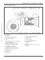
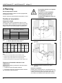
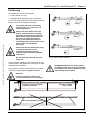
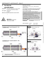
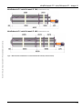
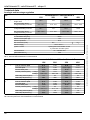
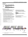
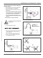
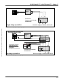
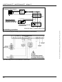
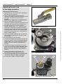
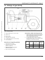
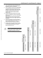
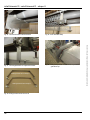
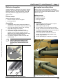
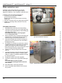
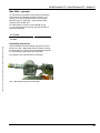
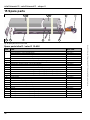
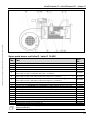
BROCSCH115.1 Contents 1 2 Introduction ................................................................................................................ 3 Your Safety ................................................................................................................ 3 SCHWANK GmbH Bremerhavener Str. 43 • 50735 Cologne • Germany Postfach 62 02 49 • 50695 Cologne • Germany Tel.: + (49) (0) 221- 7176 0 Fax: + (49) (0) 221- 7176 288 Internet: www.schwank.de Schwank companies in: Austria ▪ Benelux ▪ Canada ▪ Czech Republic ▪ France ▪ Germany ▪ Great Britain ▪ Hungary ▪ Poland ▪ Romania ▪ Russia ▪ USA ▪ Distribution in more than 40 countries worldwide Version 004 infra_calor D shape U Australia 43/13 Technical specification subject to change Notes for your safety .................................................................................................................... 3 3 Scope of Delivery ...................................................................................................... 4 4 Planning ..................................................................................................................... 6 Position of suspension .................................................................................................................. 6 Positioning .................................................................................................................................... 7 Air supply / Exhaust Requirements .............................................................................................. 8 5 Legal Requirements ................................................................................................ 11 6 Operating ................................................................................................................. 11 Switching on the heater .............................................................................................................. 11 Switching off the heater .............................................................................................................. 11 Fault ............................................................................................................................................ 11 Maintenance ............................................................................................................................... 11 7 Technical specification ............................................................................................ 12 Technical data ............................................................................................................................ 14 8 Operating description .............................................................................................. 15 9 Assembly instructions .............................................................................................. 16 10 Installation instructions ........................................................................................... 20 Gas-pipe-system and mounting of heaters ................................................................................. 20 Electrical installation (wiring diagram) ....................................................................................... 22 11 Commissioning instructions ................................................................................... 25 Adjusting nominal thermal load at single-stage operation .......................................................... 25 Adjusting thermal load at two-stage operation........................................................................... 26 Adjusting thermal load for modulating operation ........................................................................ 27 12 Service guide / Trouble shooting ............................................................................ 28 13 Change of gas family ............................................................................................... 29 14 Accessories ............................................................................................................. 30 Ball guards .................................................................................................................................. 30 Reflector elongation .................................................................................................................... 33 Set angled mounting tubes ......................................................................................................... 33 Water protection cover ............................................................................................................... 34 Gas filter - groups ....................................................................................................................... 35 15 Spare parts .............................................................................................................. 36 Spare parts infra D / calor D 15-40U .......................................................................................... 36 Spare parts burner unit infra D / calor D 15-40U ........................................................................ 37 16 AGA Certification ..................................................................................................... 38 17 EC type examination certificate ............................................................................... 39 18 EC declaration of conformity .................................................................................. 41 infraSchwank D / calorSchwank D - shape U 1 Introduction Thank you for choosing a high efficiency SCHWANK radiant tube. Your infraSchwank D / calorSchwank D is a modern and low-pollution tube heater for economic and comfortable heating of industrial and commercial buildings. The design and operation of the heater are according to the requirements of the existing standards. Version 004 infra_calor D shape U Australia 43/13 Technical specification subject to change Please read this manual carefully before using the heater. Please follow carefully all instructions and warnings. The manufacturer will not be held responsible for damages resulting from installation errors or failure to comply with the manufacturer’s instructions. Grey marked text shows information to two-stage or modulating operation for tube heaters infraSchwank D / calorSchwank D Follow carefully all warnings in chapter 2 “Your Safety”. These tube heaters are constructed exclusively for the application of large industrial and commercial space heating. Any other use is not permitted and therefore Schwank is not liable for any improper use. Notes for your safety This appliance is designed according to the requirements of the existing standards. Nevertheless it is possible that dangers for you and others result from the installation and/or operating errors. To avoid this, please read and follow the instructions carefully. General Notes Only use the radiant tube if it is in a technically faultless condition. This manual is an integral and essential part of the product and must be given to the user. Keep the manual near the heater. Any person pursuing any of the following tasks must read this manual: operating assembling installation commissioning maintenance / trouble shooting You need an explicit permission from the manufacturer for any kind of changes and reconstruction. Use original spare parts only. 2 Your Safety You will find the following symbols in this manual: Danger! Note that you and others can be hurt. Safety for the electrical equipment Danger of electrical shocks! Electrical shocks can be very dangerous! The electrical installation must be carried out by a qualified service engineer following the existing national and international standards. Check the electrical equipment regularly. Defect wires etc. must be replaced immediately. Attention! Note that the appliance can be damaged. Danger! Note that electrical shocks can be very dangerous. Pay attention while working on the electrical equipment. The appliance must be cut off from the power supply while working with the electrical equipment. Make sure that nobody can connect the appliance to the power supply while you are installing or maintaining the unit. After-sales Service For all installation operations, start-up, gas changes, etc. always consult a qualified service engineer. In case of doubt, please contact: Advice! You find additional instructions about the application/handling of the heater. Mr. John Balass Devex Systems Pty Limited 5/83 Bassett St Mona Vale NSW 2103 Tel: 02 9997 2811 Fax: 02 9997 7852 E-mail: [email protected] 3 infraSchwank D / calorSchwank D - shape U 3 Scope of Delivery reflector long turnaround box turbulator reflector short suspension bracket burner unit tube flange packing Radiant tube infraSchwank D / calorSchwank D 20U Scope of Delivery The radiant tube infraSchwank D / calorSchwank D consists of: Accessories Control box with on/off switch and indicator lamp Burner-unit with gas-burner, pre-mixing chamber, ignition and control unit, firing device, gas combination valve (single-, two-stage or modulating), air differential pressure switch, electrical plug connection and fan Temperature regulating device Radiant tubes with turnaround box, flange packing Supply air- / exhaust flue-system Corrosion resistant reflector with end cap and brackets for hanging (calorSchwank D: isolated reflectors) Brackets for wall mounting of angled position (15-30°) for infraSchwank D / calorSchwank D Gas cock (gas connection) Gas hose connection Gas filter Flue gas adapter Ball protection grids (for sport halls) Reflector elongations Set for angled mounting Water protection cover (stainless steel) 4 Version 004 infra_calor D shape U Australia 43/13 Technical specification subject to change Fig 1: tube bar infraSchwank D / calorSchwank D - shape U Version 004 infra_calor D shape U Australia 43/13 Technical specification subject to change Structure of the burner unit Fig. 2: Burner unit 1. Controller 2. Air differential pressure switch 3. Fan air restrictor plate 4. Fan 5. Air baffle plate (only 15 / 20 / 30 / 40U) 6. Gas combination valve (single-, two-stage or modulating) 14. Ignition and ionisation electrode 15. Ignition cable 16. Ionisation cable 17. 3-pin power supply socket 18. Locking screw 19. Venturi 7. Test nipple connection pressure 20. Burner baffle (only 15 / 20 / 30 / 40U) 8. Test nipple nozzle pressure 21. Gasket 9. Adjustment screw nozzle pressure 10. Adjustment screw start step valve 11. Inspection glass 12. Burner cup 13. Burner nozzle 5 infraSchwank D / calorSchwank D - shape U 4 Planning Do not place articles on or against this appliance. Room temperature control Do not use or store flammable materials near this appliance. Radiant tube heating-systems must be equipped with a temperature control. Do not spray aerosols in the vicinity of this appliance while it is in operation. Section heating is allowed without temperature control. Position of suspension Suspension height Radiant tubes must be positioned so that no one in the radiation area is exposed to an extreme high heat level. This is ensured when the minimum suspension heights shown in the following table are adhered to: Suspension height in m 2 (max. radiation 200 W/m ) A = horizontal B = angled (30°) 3.5m 4.0m 4.8m 5.5m 3.1m 3.6m 4.3m 4.9m 60 (15U) 75.9 (20U) 115.9 (30U) 155.8 (40U) Tab 1: Key: Minimum suspension heights A = Minimum height when hanging horizontally B = Minimum height when hanging angled b [cm] Fig 3: Suspension heights and distances for horizontal application d [cm] Type a [cm] infra calor infra calor 15 U 110 20 10 50 15 15 20 U 110 20 10 50 15 15 30 U 130 20 10 50 15 15 40 U 170 25 10 50 25 15 Tab 2: c [cm] Safe distances Key: a = Minimum radial safety distance (inside radiation area) b = Minimum upper safety distance when hanging horizontally c = Minimum upper safety distance when hanging angled d = Minimum lateral distance to supply pipes outside radiation area Distances to flammable materials in the radiant area Radiant tubes must be positioned so that the surface temperature of components with flammable materials, flammable equipment, stored flammable materials not exceed 65°C above ambient. 6 Fig 4: Suspension heights and distances for angled application Direction of radiation Radiant tubes infraSchwank D / calorSchwank D can be positioned horizontal or at an angle (max. 30° from vertical). For this purpose suspension steel chains and cables are installed at the suspension brackets. Version 004 infra_calor D shape U Australia 43/13 Technical specification subject to change Nominal thermal load in MJ/h (type) infraSchwank D / calorSchwank D - shape U Positioning The radiant tube can be mounted with chains (links min. 4 mm) adjustable steel cable (Schwank accessories) If you chose chains please use bolts with lock nuts for fixing the chain to the suspension bracket. wrong Version 004 infra_calor D shape U Australia 43/13 Technical specification subject to change The radiant tube has to be fixed by vertical chains etc. to the roof or to supporting devices. Chains and steel cables have to be fixed in vertical direction or slightly diagonally outwards above the fixing points of the suspension brackets to the roof or to supporting devices. Fixing of the suspension cables or chains diagonally inwards to the centre of the heater is not permitted (see Fig 5). wrong Please note that the radiant tube being in operation expands several centimetres because of thermal expansion. Avoid therefore inflexible suspension. Do not use fixing elements like open hooks etc. Hang the heater in balance. We recommend the use of turnbuckles or adjustable steel cable grips for ease of adjustment and balance. Fixing points for chains or steel cables on the heater are shown in Fig. 8 and 9 on pages 12 and 13. correct Fig 6: Slope of radiant tube heater SCHWANK GmbH will not accept liability for damages caused by incorrect mounting of the burner unit. Correct mounting is the responsibility of the installer. Attention! If you do not align the burner unit correctly the device can be damaged. x x Correct = vertical or slightly diagonally outwards 15/20/30U: x=15mm 40U: x=20mm Wrong = diagonally inwards Fig 5: Chains and steel cable mounting 7 infraSchwank D / calorSchwank D - shape U Air supply / Exhaust Requirements Air supply / exhaust systems The calculation of air supply / exhaust requirements of a building heated by radiant tube heaters is subject of Australia Standard AS 5601. Please follow local bylaws as well. For the radiant tube infraSchwank D / calor SchwankD the following air supply / exhaust systems are possible: Please see the max. lengths of combustion air supplyand exhaust flue pipe on page 9 (Tab 3, point 3). 1. Indirect flue into the room (Type A3 without exhaust system, combustion air from inside the room) Place of Installation 2. Flued with individual exhaust system, combustion air from inside the room (Type B23) The room to be heated must have an air volume of minimum 10 m³ for each kW of the nominal thermal load of the installed heater. 3. Flued with individual exhaust system, combustion air from outside the room (Type C) Air supply (combustion air from inside the room, types A3 and B23) 4. Flued with flue collecting system and central flue fan – combustion air either from inside or from outside (according to EN 777, Type D) In halls and buildings with a normal air change by means of joints and gaps it is not necessary to install additional equipment to ensure combustion air supply. 1. Indirect flue into the room (Type A3 without exhaust system combustion air from inside the room) The exhaust air of the tube heater has to be conducted from the inside of the room to the outside. Conduction of the exhaust air may be carried out with one of the following 3 methods: a) Thermal ventilation: Combustion air and exhaust air are to be conducted through fixed outlets positioned on the roof or on the walls of the building. b) Mechanical ventilation: Combustion air and exhaust air are to be conducted through one or more fans positioned on the roof or on the walls of the building. c) Natural ventilation: Combustion air and exhaust air are to be conducted through outlets as a result of differences in pressure and in temperature between the internal and external side of a building. For exact dimensioning and positioning of supply air and exhaust air outlet of the building according AS 5601 or please contact Schwank GmbH 8 Version 004 infra_calor D shape U Australia 43/13 Technical specification subject to change Heating installations with combustion air from inside the room are only allowed in rooms without string air pollution. Otherwise use system with combustion air from outside (type C). infraSchwank D / calorSchwank D - shape U 2. Exhaust flue with individual exhaust system combustion air from inside the room (Type B23) 4. Exhaust flue with flue collecting system and central flue fan (according to EN 777, Type D) Only use this system in rooms with no air pollution and without relevant pressure differences to outside. Otherwise use type C. The heating installation must not exceed 10 radiant tubes. The exhaust air of each tube is collected via a central collecting tube system by a central flue fan and led to the chimney. Planning, construction and layout of such installations must be carried out by Schwank employees, as well as commissioning. The strict observance of the Schwank layout-drawings and calculation figures are the precondition of the manufacturer’s warranty. 3. Exhaust flue with individual exhaust system combustion air from outside the room (Type C) Combustion air and exhaust air are to be conducted by a temperature stable, concentric pipe from a wall or roof entrance. Version 004 infra_calor D shape U Australia 43/13 Technical specification subject to change Max. length of the concentric pipe can be 6 m plus two 90° elbows. The concentric pipe ends at a bifurcated pipe. Please ensure that the connection for exhaust air between heater and bifurcated pipe is a flexible pipe. Do not use back-pressure valves or dampers in the exhaust flue. If the radiant tubes will be installed without their individual flue fans, please note that it could be necessary to install in the collecting tube behind each radiant heater a damper or a pressure-balancing device. This ensures a precise regulation and an even exhaust flue of each radiant tube. See technical instruction infraSchwank D / calorSchwank D with flue collecting system infraSchwank D/ calorSchwank D, shape U Max. length max. number between heater Ø of of elbows and roof/wall air/exhaust flue (90°) entrance 6m 2 100 mm Tab 3: air / exhaust flue 9 infraSchwank D / calorSchwank D - shape U Indirect flue into the room with flue gas diverter Installation with indirect flue into the room must be mounted with flue gas diverter to avoid flow back of flue gas in combustion air stream. Note that the flue gas diverter (code no. 126 7018 0) is mounted in a position so that the flue gas is diverted from the burner. flue gas diverter with right mounting position Fig 7: Flue less appliance with flue gas diverter 10 Version 004 infra_calor D shape U Australia 43/13 Technical specification subject to change To prevent CO2 impingement on wall when configured as an indoor flue less appliance a clearance of 1200mm from the flue outlet is required. infraSchwank D / calorSchwank D - shape U 5 Legal Requirements 6 Operating We recommend that these installation guidelines should be observed with the relevant Building Standards Regulations of your country. Comply with any local by-laws and the current IEE Wiring Regulations. Version 004 infra_calor D shape U Australia 43/13 Technical specification subject to change Notwithstanding their limited scope, the appliance should be installed by a competent person in accordance with the relevant provisions of the Gas Safety (Installation and Use) Regulations. Caution must also be taken of any obligations arising from the Health and Safety of Work Act. Full compliance with all relevant regulations, including amendments in force at the time of installation is a requirement of our warranty. The installation must be carried out by a qualified engineer following the manufacturer’s instructions. SCHWANK will not accept liability damages caused by improper assembly and/ or operating of the heater. Proper assembly and operation is the responsibility of the user. Switching on the heater Switch on the heater. The main switch is on the control box. After a pre-purge period of about 25 sec. the ignition starts. Switching off the heater Switch off the heater. If the radiant tube is controlled by a thermostat the heater will be switched on and off automatically. Fault If no flame is reported during the pre-purge period and the safety time (approx. 30 sec.) the heater repeats the ignition process. If there is no flame after the second ignition process the radiant tube switches off automatically and is locked. Investigation and repair must be carried out by authorized personnel. After clearance of the fault the heater can be reset. Lock release (Reset) Interrupt the electric power supply for 3 seconds. Maintenance Maintenance and servicing of the appliance must be carried out by authorised personnel and not less than once a year. Servicing of the heater is essential for continued efficient operation. After any servicing, the heater must be recommissioned as detailed in Chapter 12. 11 infraSchwank D / calorSchwank D - shape U 7 Technical specification Appliance Automatic heating device, heat transfer by mean of infrared dark radiation. Fuel Types Natural gas Propane Electrical connection Single phase A.C. 230 V, N, PE - 50Hz (cycles) (approx. 80 VA) Power supply for the heater and fan are connected to the socket of the burner box. To set the burner box free of voltage, it is only necessary to remove the plug of the power supply. Max. connection pressure Natural Gas: 5.0kPa Exhaust gas Connection Flue gas pipe connection Ø 100 at exit of tube Gas connection 15-30U 40U Type Natural Gas LPG 15-40U 1.13kPa 2.75kPa R=1/2’’ male R=3/4’’ male Detail A infraSchwank D / calorSchwank D 15U Cross dimensions at burner unit 15-40U A=80mm (all dimensions in mm) Detail A / B infraSchwank D / calorSchwank D 20U (all dimensions in mm) Fig 8: 12 Measurements infraSchwank D / calorSchwank D 15U and 20U (view from below) Detail B Cross dimensions reflector valid for all types Version 004 infra_calor D shape U Australia 43/13 Technical specification subject to change Attention! The connection cable for the lifting magnet of 2-stage gas combination valve must connect from the connection box (230 V/50 Hz) to the provided luster terminal inside of the burner unit. The connection cable for the lifting magnet of modulating gas combination valve must connect direct from the modulation box to the lifting magnet. The distance between modulation box and burner unit should be < 1,5m. Minimum connection pressure in front of valve infraSchwank D / calorSchwank D - shape U infraSchwank D / calorSchwank D 30U (all dimensions in mm) Version 004 infra_calor D shape U Australia 43/13 Technical specification subject to change infraSchwank D / calorSchwank D 40U (all dimensions in mm) Fig 9: Measurements infraSchwank D / calorSchwank D 30U and 40U (view from below) 13 infraSchwank D / calorSchwank D - shape U Technical data for single and two-stage regulation Gas 15U Natural gas Gas consumption [MJ/h] 1) single state Propane 2) infraSchwank D / calorSchwank D 20U 30U 40U 59.9 75.9 115.9 155.8 Gas consumption [MJ/h] 2-stage/modulating max./min. 59.9 - 44.7 75.9 - 57.2 115.9 - 87.9 155.8 - 119.9 Gas consumption [MJ/h] 2-stage/modulating max./min. 58.7 74,4 113.5 152.6 Gas consumption [MJ/h] 2-stage/modulating max./min. 58.7 - 43.8 74.4 - 56.0 113.5 - 86.1 152.6 - 117.4 54 / 68 75 / 95 92 / 119 130 / 171 Weight infra / calor [kg] of air/exhaust flue [mm] Electrical consumption [W] Ø 100 104 IP 20 Electrical protection 3 R /4 “ R½“ Gas connection (male) 230 V/ 50 Hz ~ Ignition / Control Spark ignition and ionisation control by automatic controller system CE - 0085 BO 0037 7652 CE-Identification AGA Certification no. 3 1) Hi,B = 37.8 MJ/m / 2) Hi,B = 95.8 MJ/m 3 Tab 4: Technical data infraSchwank D / calorSchwank D infraSchwank D / calorSchwank D 15U 20U 30U 40U Gas Burner nozzle [mm] Fan air restrictor plate Air baffle plate Burner baffle plate Nozzle pressure [kPa] Natural gas 1) 1-stage 2-stage Start step pressure [kPa] Start step adjustment [°] Burner nozzle [mm] Fan air restrictor plate Air baffle plate Burner baffle plate Nozzle pressure [kPa] 1-stage 2-stage Start step pressure [kPa] Start step adjustment [°] Propane 2) 3 1) Hi,B = 37.8 MJ/ m / 2) Hi,B = 95.8 MJ/m 3 3.75 D 15 D 15 Ø 50 0.87 0.87 / 0.6 0.4 MIN 2.30 D 15 D 15 Ø 50 2.4 2.4 / 1.4 1.2 MAX *) IA= inlet angle plate Tab 5: Function parts burner unit infraSchwank D / calorSchwank D 14 4.10 D 20 D 20 Ø 50 0.87 0.87 / 0.6 0.4 MIN 2.50 D 20 D 20 Ø 50 2.4 2.4 / 1.4 1.2 MAX 5.35 D 30 D 30 + spin Ø 65 0.87 0.87 / 0.6 0.4 MIN 3.15 D 30 D 30 + spin Ø 65 2.4 2.4 / 1.4 1.2 MAX 6.25 D 40 D 40 U / 0.87 0.87 / 0.6 0.3 MIN 3.60 D 40 D 40 U Ø 65 2.4 2.4 / 1.4 1.2 MAX Version 004 infra_calor D shape U Australia 43/13 Technical specification subject to change Electrical supply infraSchwank D / calorSchwank D - shape U 8 Operating description Start-up If heat demand exists, the fan will start up automatically. A differential pressure arises in the burner box, which is reported to the ignition unit via the differential pressure switch. After a pre-purge period of about 25 seconds the automatic ignition starts (max. ignition time 5 sec.). The twin solenoid valve with pressure regulator opens the gas supply to the burner in 2 steps. The burner flame is controlled by an ionisation electrode. The ignition is switched off, if the ionisation electrode reports a flame to the ignition and control unit within the safety time. Version 004 infra_calor D shape U Australia 43/13 Technical specification subject to change If the ignition process fails, the ignition unit repeats the start-up for one more time. Operation A very long laminar flame is created in the first tube by the special burner construction. The hot flue heats the tube surface while being fed through the tubes by the fan. The hot tubes emit long-waved infrared radiation which is directed to the room by the reflector construction. The radiant tube infraSchwank D / calorSchwank D work with a closed combustion system. The combustion air is taken from the room or from the outside. The flue is evacuated indirectly into the room or directly by the exhaust pipe or by a special air/exhaust pipe system. For optimal adaption of heaters´ performance to the heat demand of the building heaters are offered in 2-stage or modulating operation. Start and ignition of the heater has always to be in full load. After a time of minimal 1 minute the heater can be switched to small step. Fault If no flame is reported during the pre-purge period (including 1 repetition of ignition process), the ignition unit will switch off the radiant tube and will lock it. Investigation and repair must be carried out by authorized personnel only. After clearance of the fault, the interlock can be reset. The lock release can carried out by an interruption of the electric power supply for 3 sec. A new start-up begins. If no flame signal is reported to the ignition and control unit during operation, the solenoid valve shuts and stops the gas supply immediately. A new start-up process is repeated. Troubleshooting: page 28 Monitoring of the combustion air supply The combustion air supply is permanently controlled by the differential pressure switch during the operation. If the differential pressure switch is not in rest position during the start-up the operation will not start. If the operating contact is not closed during the pre-purge the system will set in interference release. If combustion air supply fails during operation (lack of air), the differential pressure switch will close the gas combination valve and stop the gas supply. A new startup process is to be repeated. . 15 infraSchwank D / calorSchwank D - shape U 9 Assembly instructions infraSchwank D / calorSchwank D 15U Tools you need • hexagonal wrench or ratchet (width: 10, 13) • socket wrench (width: 7 and 8) Note before mounting Note the distance measure of suspension brackets. Flanges are mounted with flange packing (each 4 screws/washers/lock washers/nuts M8). Start mounting the heater at the turnaround box connection. Tube with turbulator (with paint mark) has to be mounted behind the turnaround box (flow direction). The paint mark showing to the turnaround box! Tube bars have to be fixed by nuts/lock washers/3Dwashers M8 on the suspension bracket. First the reflector will be fixed on the U-bend connection by self-tapping screws. For insulated reflectors (calorSchwank D) the reflector end with notch on sides shows to the turnaround box. Accessory: Flue gas adapter code no. 126 7035 0 Adapter is mounted at the end of the tube with gasket. Flue gas connection (Type B23, C): version stainless steel: Note that the flue gas flexible pipe is mounted at the end of the tube with gasket. The other reflector ending will be shoved under the clip of the suspension brackets. Reflector and front plate have to be fixed by self-tapping screws. Mounting of burner unit with valve on the top. Flue gas diverter Fig. 10: Mounting of infraSchwank D / calorSchwank D 15U (all dimensions in mm) 16 Version 004 infra_calor D shape U Australia 43/13 Technical specification subject to change Turn welding line of the tubes to the side. Indirect flue into the room (Type A3): Flue gas diverter code no. 126 70180 Note that the flue gas diverter is mounted in a position so that the flue gas is diverted from the burner. infraSchwank D / calorSchwank D - shape U Assembly infraSchwank D / calorSchwank D 20U Tools you need • hexagonal wrench or ratchet (width: 10, 13) • socket wrench (width: 7 and 8) Note before mounting Note the distance measures of suspension brackets. Flanges are mounted with flange packing (each 4 screws/washers/lock washers/nuts M8). Version Version004 004infra_calor infra_calorDDshape shapeUUAustralia Australia43/13 43/13Technical Technicalspecification specificationsubject subjecttotochange change Version 004 infra_calor D shape U Australia 43/13 Technical specification subject to change Start mounting the heater at the turnaround box connection. Turn welding line of the tubes to the side. Tube with turbulator (with paint mark) has to be mounted behind the turnaround box (flow direction). The paint mark showing to the turnaround box! Tube bars have to be fixed by nuts/3D-washers/lock washers M8 on the suspension brackets. Start the reflector mounting at the turnaround box connection with the longest reflector L=3000mm. Reflector will be fixed on the turnaround box connection by self-tapping screws. For insulated reflectors (calorSchwank D) the reflector end with notch on sides shows to the turnaround box. Indirect flue into the room (Type A3): Flue gas diverter code no. 126 70180 Note that the flue gas diverter is mounted in a position so that the flue gas is diverted from the burner. Accessory: Flue gas adapter code no. 126 7035 0 Adapter is mounted at the end of the tube with gasket. Flue gas connection (Type B23, C): version stainless steel: Note that the flue gas flexible pipe is mounted at the end of the tube with gasket. The other reflector endings will be shoved under the clips of the suspension brackets. The short reflector L=1500mm is mounted at the front of the heater. Reflectors will be jointly fixed by 3x M 5 screws and self-locking nuts. Reflector and front plate have to be fixed by selftapping screws. Mounting of burner unit with valve on the top. Fig. 11: Mounting of infraSchwank D / calorSchwank D 20U (all dimensions in mm) Flue gas diverter 17 infraSchwank D / calorSchwank D - shape U Assembly infraSchwank D / calorSchwank D 30U Tools you need • hexagonal wrench or ratchet (width: 10, 13) • socket wrench (width: 7 and 8) hand rivet tool, drill machine, drill 4.9mm Note before mounting Fig. 12: Mounting of infraSchwank D / calorSchwank D 30U (all dimensions in mm) Flue gas diverter 18 Version 004 infra_calor D shape U Australia 43/13 Technical specification subject to change Note the distance measures of suspension brackets. Indirect flue into the room (Type A3): Flanges are mounted with flange packing Flue gas diverter code no. 126 70180 (each 4 screws/washers/lock washers/nuts M8). Note that the flue gas diverter is mounted in a Start mounting the heater at the turnaround box position so that the flue gas is diverted from the connection. burner. Turn welding line of the tubes to the side. Accessory: Tube with turbulator (with paint mark) has to be Flue gas adapter code no. 126 7035 0 mounted behind the turnaround box (flow direction). Adapter is mounted at the end of the tube with The paint mark showing to the turnaround box! gasket. Supporting sleeve for first flange connection: Insert half of the supporting sleeve into first heater Flue gas connection (Type B23, C): tube (slot on top). Drill Ø 4.9mm hole through the version stainless steel: tube and sleeve and fix it by rivet. Mount the second Note that the flue gas flexible pipe is mounted at the tube and fix the sleeve by the rivet as well. Fix the end of the tube with gasket. rivets always in the opposite position lateral to the tube. Use only stainless rivets. Tube bars have to be fixed by nuts / 3D washers / lock washers M8 on the suspension brackets. Start the reflector mounting at the turnaround box connection. Reflector will be fixed on the turnaround box connection by self-tapping screws. For insulated Supporting sleeve reflectors (calorSchwank D) the reflector end with 4 rivets (stainless steel) 4,8mm notch on sides shows to the turnaround box. hole to drill 4,9mm The other reflector endings will be shoved under the clips of the suspension brackets. Reflectors will be jointly fixed by 3x M 5 screws and self-locking nuts. Reflector and front plate have to be fixed by selftapping screws. Mounting of burner unit with valve on the top. infraSchwank D / calorSchwank D - shape U Assembly infraSchwank D / calorSchwank D 40U Tools you need • hexagonal wrench or ratchet (width: 10, 13) • socket wrench (width: 7 and 8) Version Version004 004infra_calor infra_calorDDshape shapeUUAustralia Australia43/13 43/13Technical Technicalspecification specificationsubject subjecttotochange change Version 004 infra_calor D shape U Australia 43/13 Technical specification subject to change Note before mounting Note the distance measures of suspension brackets. Flanges are mounted with flange packing (each 4 screws/washers/lock washers/nuts M8). Start mounting the heater at the turnaround box connection. Turn welding line of the tubes to the side. Tube with turbulator (with paint mark) has to be mounted behind the turnaround box (flow direction). The paint mark showing to the turnaround box! Tube bars have to be fixed by nuts/3D-washers/lock washers M8 on the suspension brackets. Start the reflector mounting at the turnaround box connection. Reflector will be fixed on the turnaround box connection by self-tapping screws. For insulated reflectors (calorSchwank D) the reflector end with notch on sides shows to the turnaround box. The other reflector endings will be shoved under the clips of the suspension brackets. Reflectors will be jointly fixed by 3x M 5 screws and self-locking nuts. Reflector and front plate have to be fixed by self-tapping screws. Mounting of burner unit with valve on the top. Fig. 13: Mounting of infraSchwank D / calorSchwank D 40U (all dimensions in mm) Indirect flue into the room (Type A3): Flue gas diverter code no. 126 70180 Note that the flue gas diverter is mounted in a position so that the flue gas is diverted from the burner. Accessory: Flue gas adapter code no. 126 7035 0 Adapter is mounted at the end of the tube with gasket. Flue gas connection (Type B23, C): version stainless steel: Note that the flue gas flexible pipe is mounted at the end of the tube with gasket. Flue gas diverter 19 infraSchwank D / calorSchwank D - shape U 10 Installation instructions pressure drop value of the Schwank gas-pipe-systems see table 7. Minimum connection pressures in front of valve infraSchwank D / calorSchwank D shape U Danger of fire and explosion! Unprofessional handling of gas pipes, gas connections and the appliance can produce gas leaks. It is highly dangerous if gas is ignited! Working on gas pipes and the appliances is only allowed by approved installers. Mount the flexible connection, so that it can compensate the longitudinal expansion of the tube. nozzle pressure start step pressure [kPa] single stage [kPa] two stage max. - min. [kPa] [kPa] 15 - 40U 1.13 0.87 0.87 - 0.6 0.4 - 0.5 Propane* 15 - 40U 2.75 2.4 2.4 - 1.4 1.2 Natural gas* * Natural gas: HS,B: 37,8 MJ/m3 Propane: HS,B 95.8 MJ/m3 Tab 6: min. connection pressures with single and two stage regulation in front of gas combination valve Pressure drop Schwank gas-pipe-systems infraSchwank D / calorSchwank D shape U Natural gas a Propane type gas pipe system 15 - 30U 1/2" / L=800mm pressure drop [kPa] 0.2 40U 3/4" / L=800mm 0.25 15 - 30U 1/2" / L=800mm 0.1 40U 3/4" / L=800mm 0.1 Tab 7: Pressure drop Schwank gas-pipe-systems b The max. connection pressure for natural gas is 5.0kPa! Fig 14: Longitudinal expansion Gas-pipe-system and mounting of heaters In case of contaminated gas pipes and generally at gas pipes of welded black steel have to be mounted gas filter - groups directly in front of the heater (see page 35). All gas installation work must be carried out only by an authorised person in accordance with standard AS 5601. Additional installation notices of national or local institutions must be observed. The pipe must be dimensioned in a way that the minimum connection pressure in front of the gas combination valve of the individual devices is available at the nominal thermal load of the entire system, according to table 6. Please consider the pressure drop of the upstream mounted gas connection and gas filter. For the detailed 20 Flexible final connections to the heater must either a) hose assembly to AS/NZS 1869 of a suitable size, temperature and pressure rating or b) a limited flexibility connector to AS 4631 of a suitable size. Version 004 infra_calor D shape U Australia 43/13 Technical specification subject to change Only use flexible connections for the radiant tube regarding: • gas • electricity and • air (if necessary) type min. connection pressure infraSchwank D / calorSchwank D - shape U Note the following points while installing the gas-pipe-system: Use only gas lines as per national standards. 430 mm (+/- 10%) Never hang heaters on the gas pipes. Mount a manual gas cock upstream of every radiant tube. Close all gas cocks before carrying out the leak test and disconnect the connection between the gas cock and the burner to avoid damages to the gas regulator and gas combination valve. Fig 16: lateral connection 90° bend Clean gas pipes before the installation of the heater. Reconnection after pressure control and expansion. 430 mm (+/- 10%) Please observe the national standards. Connect the heater with an approved flexible hose. a = 320 mm +/- 10% h = 150 mm h: allowable height displacement for mounting Use the following hose length: 15-30U R ½“ length 800mm 40U R ¾“ length 800mm Mount only a flexible hose with 90° bend or with 2 x 90° elbow with 180° bend according to fig. 15, 16 and 17. Keep the specified installation dimensions. Wrong mounting of flexible hoses shown in Fig. 18 (sketches to) Fig. 17: Alternative flexible hose 180° -bend with 2 x 90° elbow 430 mm (+/- 10%) Version 004 infra_calor D shape U Australia 43/13 Technical specification subject to change Fig. 16: lateral connection 90° bend 430 mm (+/- 10%) Fig 15: Stand connection 90° bend Fig 18: Wrong mounting of flexible hoses 21 infraSchwank D / calorSchwank D - shape U Gas connection has to be positioned in the axle of the heater. Otherwise torsional forces will operate on the hose! Avoid twisting of the flexible hose! (When tightening the union, counter hold the nipple on the hose.) Pay attention that the flexible hose will not be mechanically damaged by tools etc. Do not buckle the hose. Do not mount damaged flexible hoses! Damaged hoses can break due to the movement of the heater. Electrical installation (wiring diagram) Isolate the electrical supply while working at the electrical equipment of the appliance and safeguard the appliance against unintentional connection to the circuit. The gas supply and electrical cable must be situated on the outside of the radiation and combustion heat. Only use heat-resistant cables near the tubes. Electrical connection Single stage operation Route the connection cable (power supply) to the three-pin plug and connect the cables (see Fig. 19, page 23). Plug in the three-pin plug into the socket of the burner box. Connect the plug of the fan into the corresponding socket at the burner box. Pay attention of the correct polarity! If the polarity is incorrect, the firing device will not note any ionisation signal! You find the three-pin socket for the electrical supply on the burner box. 22 Route the connection cable (power supply burner unit) to the three-pin plug and connect the cables (see Fig. 20, page 23). The connection cable of the modulation spool connects by a branch box (see Fig.20, page 23). Plug in the three-pin plug into the socket of the burner box. Connect the plug of the fan into the corresponding socket at the burner box. Start and ignition of the heater has always to be in full load. After a time of minimal 1 minute the heater can be switched to small step. You find the three-pin socket for the electrical supply on the burner box. The connection cable of the modulation spool is screw on the gas combination valve. Version 004 infra_calor D shape U Australia 43/13 Technical specification subject to change Danger of electric shock! Electric shocks are highly dangerous! Working at the electrical equipment of the appliance is only allowed by professional personnel observing the current IEE regulations. Electrical connection two stage operation infraSchwank D / calorSchwank D - shape U Gas valve VK 4105C 1 Burner unit PE 2 L PE N Control box Thermocontrol Plus M / unoSchwank L single-stage operation N PE Electrical supply 1~230Volt, 50Hz, N, PE Version Version004 004infra_calor infra_calorDDshape shapeUUAustralia Australia43/13 43/13Technical Technicalspecification specificationsubject subjecttotochange change Version 004 infra_calor D shape U Australia 43/13 Technical specification subject to change Fig. 19: Connecting diagram single-stage regulation infraSchwank D / calorSchwank D Gas valve VK4115Q / VK 4105Q with lifting magnet 2-stage Burner unit 1 PE 2 Connection box 21 22 20 Time delay 1minute ignition for max. load (integrated in control box duoSchwank and Thermocontrol Plus M) L1 L2 N PE Control box Thermocontrol Plus M / duoSchwank L1 two-stage operation N PE Electrical supply 1~230Volt, 50Hz, N, PE Fig. 20: Connecting diagram two-stage regulation infraSchwank D / calorSchwank D 23 infraSchwank D / calorSchwank D - shape U GVK VK 4105N with modulating lifting magnet Burner unit 1 PE 2 o Modulation Box (distance to burner unit < 1,5m) Time delay 1minute ignition for max. load (integrated in moduSchwank and Thermocontrol Plus M) L1 L2 N PE Control box Thermocontrol Plus M / moduSchwank L1 N P Electrical supply 1~230Volt, 50Hz, N, PE modulating operation Fig 22: Wiring diagram burner unit infraSchwank D / calorSchwank D 24 Version 004 infra_calor D shape U Australia 43/13 Technical specification subject to change Fig. 21: Connecting diagram modulating operation infraSchwank D / calorSchwank D infraSchwank D / calorSchwank D - shape U 11 Commissioning instructions Before commissioning Only authorised personnel can curry out this operation. The correct operation and fixing of the heater is prerequisite for the warranty. Checking gas lines and flue system is not included in this service. Check the function of the following equipment: Version Version004 004infra_calor infra_calorDDshape shapeUUAustralia Australia43/13 43/13Technical Technicalspecification specificationsubject subjecttotochange change Version 004 infra_calor D shape U Australia 43/13 Technical specification subject to change Exhaust flue Combustion air supply Control unit Safety equipment Safety of electrical circuit Pay attention when commissioning! Vaporization of remaining grease of metal units may cause greasy mist. This kind of mist disperses after approx. 30 minutes. During this time the room has to be ventilated. Adjusting nominal thermal load at single-stage operation Attention! The pressure control unit is preadjusted on natural gas / propane. Do not put the appliance into operation uncontrolled. Adjusting the nozzle pressure 1. Open first the gas cock which is at the end of the flexible gas hose (Fig.23, page 26). 2. Open the test nipple connection pressure. Connect the pressure measuring instrument to the test nipple and determine the connection pressure. Close the test nipple after the measurement! 3. Open the test nipple nozzle pressure. Connect the pressure measuring instrument to the test nipple and determine the nozzle pressure. 4. Turn the adjusting screw on the pressure regulator slowly in the “+” or “-” -direction while continuously watching the pressure measuring instrument. Stop turning as soon as the required nozzle pressure is reached. The required nozzle pressure for natural 3 gas H (Wo,B =50.0 MJ/m ) is shown in table 5 page 14. 5. Remove the protection cap A (see Fig. 24, page 26). 6. Put the radiant tube into operation 7. Turn the adjusting screw B (see Fig. 25, page 26) on the pressure regulator slowly in the “+” or “-” direction while continuously watching the pressure measuring instrument. Stop turning as soon as the required nozzle pressure is reached. 8. Put the protection cap A on the valve after the adjusting. 9. Close the test nipple after the measurement and check if the test nipple is gas-tight. Checking adjustment 1. Turn the adjustment screw slightly to “-“ -direction. Nozzle pressure must drop immediately. If this does not happen, you must readjust the jet pressure until the point is reached at which a decrease or increase in the nozzle pressure is noticeable on the measuring instrument. 2. Close test nipple after the measurement! 3. Remove the measuring instrument and check if the test nipple is gas-tight. 25 infraSchwank D / calorSchwank D - shape U Adjusting thermal load at two-stage operation Fig 23: A B Fig 24: C Fig 25: 26 Gas cock with integrated TSD Adjusting screw nozzle pressure single stage gas combination valve D E Adjusting screw nozzle pressure with lifting magnet two stage gas combination valve Version 004 infra_calor D shape U Australia 43/13 Technical specification subject to change Adjusting the nozzle pressure 1. Open first the gas cock at the end of the flexible gas hose (Fig.23, page 26). 2. Open the test nipple connection pressure. Connect the pressure measuring instrument to the test nipple and determine the connection pressure. Close the test nipple after the measurement! 3. Open the test nipple nozzle pressure. Connect the pressure measuring instrument to the test nipple and determine the nozzle pressure. 4. Turn the adjusting screw on the pressure regulator slowly in the “+” or “-” -direction while continuously watching the pressure measuring instrument. Stop turning as soon as the required nozzle pressure is reached. The required nozzle 3 pressure for natural gas H (Wo,B =50.0 MJ/m ) is shown in table 5 page 14. 5. Take off the plastic cap E (see Fig. 25, page 26) from the lifting magnet (lift the cap with a small screw-driver) 6. Put the radiant tube into operation. 7. The electrical supply must activate for burner unit and lifting magnet to adjust the nozzle pressure of max. load. Turn the outer adjusting screw C (width 8) until the required nozzle pressure is reached. 8. The electrical supply must activate only for the burner unit to adjust the nozzle pressure of min. load. Turn the inner adjusting screw D (screwdriver 6x1) until the required nozzle pressure is reached. 9. Checking adjustment nozzle pressure as described by the single stage performance. 10. Close test nipple after the measurement and and check if the test nipple is gas-tight. 11.Put the plastic cap E on the lifting magnet. infraSchwank D / calorSchwank D - shape U Version Version004 004infra_calor infra_calorDDshape shapeUUAustralia Australia43/13 43/13Technical Technicalspecification specificationsubject subjecttotochange change Version 004 infra_calor D shape U Australia 43/13 Technical specification subject to change Adjusting thermal load for modulating operation Adjusting the nozzle pressure 1. Open first the gas cock which is at the end of the flexible gas hose (Fig.23, page 26). 2. Open the test nipple connection pressure. Connect the pressure measuring instrument to the test nipple and determine the connection pressure. Close the test nipple after the measurement! 3. Open the test nipple nozzle pressure. Connect the pressure measuring instrument to the test nipple and determine the nozzle pressure. 4. Turn the adjusting screw on the pressure regulator slowly in the “+” or “-” -direction while continuously watching the pressure measuring instrument. Stop turning as soon as the required nozzle pressure is reached. The required nozzle 3 pressure for natural gas H (Wo,B =50.0 MJ/m ) is shown in table 5 page 14. 5. Take off the plastic cap A (see Fig. 26, page 27) from the lifting magnet. 6. Put the radiant tube into operation. In case a different value has to be set the output current value in the Modulation Box has to be changed. Please follow below mentioned procedure [e.g. 12 / 8.5 mbar]: 7. Switch the jumper at the ThermoControl Plus M to “Modulation” 8. Switch on the “Chimney sweeper” mode at the ThermoControl Plus M 9. Ensure that the input pressure at the gas pressure regulator is sufficient enough [e.g. 15 mbar] 10.Push the “+/-“ button (button block “B”) so that the measured nozzle pressure will be 1 mbar below the required minimum value (e.g. 7.5 mbar). If the value cannot be adjusted, the mechanical limitation at the lifting magnet (large adjusting screw B, Fig. 26) needs to be amended. Afterwards continue with adjusting to the required minimum value 11.To adjust the maximum pressure, the jumper has to be switched to “Max”. With the “+/-“ buttons adjust the value to 1 mbar above the required maximum pressure (e.g. 13 mbar). In case the value cannot be adjusted the mechanical limitation of the lifting magnet (small adjusting screw C, Fig. 26) needs to be amended. Afterwards continue with adjusting to the required minimum value. 12. Check the minimum value and re-switch the jumper to “min” position and adjust the value if necessary (e.g. 7.5 mbar). 13. Adjustment of the mechanical pressure range of the lifting magnet: Place the jumper of the Modulation Box to the “N” position. “Chimney sweeper” mode needs to be still switched on. Disconnect the power supply (clamp 7 / 8, Fig. 27) of the Modulation Box or the connector of the lifting magnet. Adjust the minimum value to the required nozzle pressure (e.g. 8.5 mbar) at the lifting magnet. Re-connect the electrical connection at the Modulation Box (clamp 7 / 8) or the connector of the lifting magnet and adjust the required maximum value (e.g. 12mbar) at the lifting magnet. 14. Switch off the “chimney sweeper” mode. 15. Close test nipple after the measurement and and check if the test nipple is gas-tight. 16. Put the plastic cap A on the lifting magnet Fig. 26: Section of modulating lifting magnet Fig. 27: Modulation Box 27 infraSchwank D / calorSchwank D - shape U 12 Service guide / Trouble shooting Maintenance and annual check Any deviations must be fixed immediately. Defect parts must be changed directly. Pressure switches, pressure regulators, valves and safety- and ignition devices can only be maintained by the manufacturer or authorized personnel. A regular maintenance is the requirement for a faultless operation of the appliance. According to the National Standard Regulations, heating-systems with radiant tubes must be checked at least once a year. Maintenance and trouble shooting is only allowed by professional personnel that is competent and instructed in radiant tubes. Trouble Shooting fault • Fault in electrical supply • Thermostat "OFF" • Connection of ignition- and ionisation electrode is wrong Check the surface of radiant tubes Check the pollution and sooting of tubes clean (if necessary) • Differential pressure switch is defect or out of order (contact must be open) Check tightness of the tube system including connection to the burner unit Check the air/flue-system clean (if necessary) Control goes in fault position during prepurge period • Flame signal wrongfully caused by electrical defect of control Check the gas connection Leakage-test • Pressure differential is not sufficient Check the connection pressure, nozzle pressure and start step Control goes in fault position during the safety time • No flame (no ignition, valve doesn't open, no gas) Check gas filter in case of reduced line pressure, in case of pollution change filter set • No or poor flame signal (flame does not stick, bad insulation of the flame detector, no contact between burner and earth connection) Check the safety functions of the ignition- and ionisation-controls Check the valve functions Check the function of the pressure switch • W rong polarity Check the electrical connections Control goes into • Flame is off fault position during operation • Check the slope of the tubes (3 mm/m in direction of the turn around box connection) Contact of differential pressure switch opens Flame signal is poor Check the flexible gas hose and electrical connection to the burner unit Check the room temperature control Check the distances to any flammable materials Check the air/flue ventilation of the room Remove condensation water in the tube Check correct connection of the reflectors Check if the fan impeller runs correctly and is free of any damages Check the tight fit of the fan venturi Check connection and tightness of the fan to the burner unit 28 • In case of doubt, please contact: Mr. John Balass Devex Systems Pty Limited 5/83 Bassett St Mona Vale NSW 2103 Tel: 02 9997 2811 Fax: 02 9997 7852 Version 004 infra_calor D shape U Australia 43/13 Technical specification subject to change No gas (check pre- and nozzle pressure) Burner does not start Maintenance must include the following checks: reason • infraSchwank D / calorSchwank D - shape U Version 004 infra_calor D shape U Australia 43/13 Technical specification subject to change 13 Change of gas family Fig 28: Change of gas family Burner baffle (only 15 / 20 / 30 / 40U) Instruction to adjust start step pressure Burner cup 1. Adjust the start step pressure with the regulation screw, the pressure rise and the opening time can be changed between set limits. 2. The start step pressure must be set as the specified values in tab 8. Turn it clockwise with a screwdriver to increase the start step. Burner nozzle Regulation screw start step Air baffle plate (only 15 / 20 / 30 / 40U) Fan air restrictor Instruction to change the gas family 1. Change the burner nozzle 2. Adjust the new nozzle pressure (see tab. 5, page 14) 3. Adjust the new start step pressure (see tab 8, page 29 ) infraSchwank D / calorSchwank D shape U start step gas type adjustment pressure regulation screw [kPa] 15 30U MIN 0.4 Natural gas 40 U MIN 0.3 Propane 15 - 40U MAX 1.2 Tab 8: Setting regulation screw start step 4. Stick on the new rating label 29 infraSchwank D / calorSchwank D - shape U 14 Accessories Ball guards Ball protection grids acc.18032-3 for using heaters in sport halls (grid 40x40mm). Delivery scope Mounting set complete for each type of heater existing of: infra/calorSchwank D shape U 15U 20U 30U 40U 2x 2x Ball protection grid L=1443mm Ball protection grid L=1843mm 2x Ball protection grid L=2203mm 1x Ball protection grid L=2963mm 1x 1x 2x 1x 1x 1x 1x Front protection cover burner 1x 1x 1x 1x Protection grid burner end side 1x 1x 1x 1x End bracket with stud bolts M8 1x 1x 1x 1x Holding bracket (1x infra D +1x calor D) 1x 1x 1x Angled bracket with stud bolt M8 4x 4x 6x 8x Clamp 6x 6x 8x 10x Set fixing material 1x 1x 1x 1x Assembling (Description for heater infra/calorSchwank D 30 U, other types similar) 5. Assembling segments ball protection grids starts on the turnaround box (last suspension bracket for shape L). Put first segment ball protection grid L=2963 mm from below on end bracket and angled brackets of the next suspension bracket – Put clamps on stud bolts M8 and mount with self-locking nuts Mount clamp loose on one stud bolt of angled bracket for further assembling next protection grid (Fig. 33, page 32). 6. Put next segment ball protection grid L= 1843mm from below on angled brackets and mount clamp with self-locking nuts M8, clamp and angled bracket connect two segments ball protection grid to each other. Mount clamp loose on one stud bolt of angled bracket for further assembling next protection grid. 7. Put next segment ball protection grid L= 1843mm from below on angled brackets and mount clamps with self-locking nuts M8 Last segment ball protection grid L= 1843mm protects the burner unit at the bottom. 1. Mounting heater as usually acc. manual (see chapter 9, page 16 - 19). 2. Fix end bracket at inner side of turnaround box, open and close again 4 nuts M8 (Fig. 30, page 32) 3. Fix two angled brackets at each tube hanger (screws M8 x 60, nuts) (Fig. 31, page 32) Screw on angled brackets at the inner holes of suspension bracket. 4. 30 Holding bracket put loose on the first reflector (view from burner unit) and screw together with two angled brackets (screws M8 x 60, nuts), holding bracket remain axially movable NOTE: Use the right holding bracket – difference infraSchwank D or calorSchwank D – both in the delivery scope (Fig. 32, page 32)! Version 004 infra_calor D shape U Australia 43/13 Technical specification subject to change Protection grid burner top infraSchwank D / calorSchwank D - shape U 8. version stainlessAfter finish assembling of all ball protection grids fix holding bracket with 3x self-tapping screws on the reflector. 9. Push on protection grid burner top from behind over ball protection grid and burner up to the suspension bracket. Note that the lower short bending is on the left side in view from behind. Fix burner protection grid burner top with supplied cable straps or similar at bottom protection grid. Version Version004 004infra_calor infra_calorDDshape shapeUUAustralia Australia43/13 43/13Technical Technicalspecification specificationsubject subjecttotochange change Version 004 infra_calor D shape U Australia 43/13 Technical specification subject to change 10. Protection grid burner top has to be cut holes depends on installation on-site for flue system and may be gas line. Connect flue system pipes and gas line. NOTE: Select the cutouts large enough to compensate the thermal length expansion of the heater! 11. Insert front protection cover burner between front cover plate reflector and burner unit and fix it with supplied cable straps or similar on protection grid burner top (Fig. 34, page 32). 12. Protection grid burner end side has to be cut hole depends on installation on-site for gas line. Fix with supplied cable straps or similar on protection grid burner top. Please note the required number and length of segments ball protection grids for each type of heater. Compare this to the tabular and graphical overview. Fig. 29: Overview of ball guards 31 infraSchwank D / calorSchwank D - shape U Fig. 33: Loose mounted clamp Fig. 31: Fixed angled bracket on suspension bracket Fig. 34: Fixing front protection cover burner on protection grid burner top Holding bracket calor D shape U Holding bracket infra D shape U Fig. 32: Holding bracket infra D and calor D 32 Version 004 infra_calor D shape U Australia 43/13 Technical specification subject to change Fig. 30: Fixed end bracket on turnaround box infraSchwank D / calorSchwank D - shape U Reflector elongation Set angled mounting tubes Vertical elongation of reflectors b=415mm for thermal protection. The numbers reflector elongation (single sheets) is depend on required protection (one side both side, protection length) and the power of the radiant heater. Bracket to ensure form and position of reflectors when the heater is mounted angled (>15°). Bracket to mount at each junction point reflector/reflector, not at reflector end caps. Delivery scope Delivery scope Reflector elongation consist of numbers of sheet reflector elongation mounting material Mounting set consist of numbers of brackets mounting material Assembling Version Version004 004infra_calor infra_calorDDshape shapeUUAustralia Australia43/13 43/13Technical Technicalspecification specificationsubject subjecttotochange change Version 004 infra_calor D shape U Australia 43/13 Technical specification subject to change Assembling 1. Assembling and mounting tubes with reflectors complete acc. manual (see chapter 9, page 16-19). 2. Fix screws with distance sleeve and mounting angles A at hangers as required. 3. Mount end bracket B at turn around box. 4. Put reflector elongation sheet B on mounting angle A. Screw both parts together with the added clip C and screw/nut M8 and lock a nut to ensure the reflector elongation sheets. 5. Fix reflector elongation sheets to another with screw/nut M8. 1. Assembling and mounting of tubes complete (without reflectors) acc. manual (see chapter 9, page 16-19). 2. Lay first reflector on turn around box and first hanger, fix it at turn around box with two screws. 3. Fix angled bracket D with screws and nuts M8 at first hanger, bracket under reflector. 4. Put on next reflector, reflectors are fixed to another by 3 screws/nuts M5, middle screw through angled bracket. 5. Further assembling as usually acc. to manual. At heaters with axial reflector elongation the last suspension bracket on the burner side must be mounted at the junction point reflector/reflector end plate. D D A C B C Fig 35, 36: Assembling order reflector elongation Fig 37, 38: Assembling order set angled mounting 33 infraSchwank D / calorSchwank D - shape U Water protection cover Protection cover of the burner unit 15-40U with electrical protection class IP 55 against water or aggressive mediums, cover complete in stainless steel. In delivery scope a mounting set existing of: Protection cover with inlet air adapter (premounted and sealed), hinged cover plate and premounted surrounding rubber seal Gas inlet connection with union fitting (premounted) Gasket for mounting water protection cover and radiant tube Assembly instruction Divide gas inlet connection at the union fitting 2. Install with sealant the half of the divided gas inlet connection with coupling fitting to male thread gas connection burner unit. Note 40kW: First replace reducing nipple ¾“x ½“ from burner unit! 3. Mount complete burner including burner baffle into protection box, front fixing bolt at burners flange reaches through front of the protection box. 4. Pass other half gas inlet connection through PG gland and connect with burner unit. Union fitting first tighten by hand. 5. Stick gasket on protection box with silicon. Mount complete protection box with burner unit inside at radiant tube flange with gasket between tube flange and protection box. Fix front fixing bolt of the burner unit tight with flange radiant tube. 6. Tighten union fitting of the gas inlet connection with tool. 7. Assemble electrical connection through PG grand and connect with device plug, if necessary pass cable for 2-stage or modulating regulation through the second PG grand. 8. Fit tight the counter nuts of all PG glands. 9. Connect the heater with an approved flexible gas hose. Note 40kW: Mount reducing nipple ¾“x ½“on outer thread gas inlet connection with sealant! 10. Start tube heater, check gas pressures. 11. Close cover plate water protection box with two wing screws. 34 Fig. 39: Mounted burner unit in protection cover with gas inlet and electrical connections Fig. 40: Complete mounted and closed water protection cover Version 004 infra_calor D shape U Australia 43/13 Technical specification subject to change 1. infraSchwank D / calorSchwank D - shape U Gas filter - groups To avoid technical problems with the gas combination valves which are caused by pollution of dust or rust coming out of the gas pipe should to be mounted a gas filter-group ¾“ (gas filter + premounted double nipple) for tube heater 40U. For tube heaters 15-30U a similar gasfilter-group ½“ has to be ordered in case the gas pipe is made of black steel (welded). gas filter-group Rp ½“ for 15-30U gas filter-group Rp 3/4“ for 40U code no: 192 0756 0 code no: 192 0757 9 Version Version004 004infra_calor infra_calorDDshape shapeUUAustralia Australia43/13 43/13Technical Technicalspecification specificationsubject subjecttotochange change Version 004 infra_calor D shape U Australia 43/13 Technical specification subject to change Assembly instruction Direct installation between flexible gas pipe and valve burner unit, with a slight radial slope for better cleaning the filter bottom! In case of strong polluted filter pad use the corresponding spare part set for gas filter. Pay attention to the flow direction of the filter! Fig 41: Mounted gas filter-group at tube heater 35 infraSchwank D / calorSchwank D - shape U 15 Spare parts Fig. 42: Spare parts infra D / calor D 20U Pos. Part 1 Art.-No. Burner unit infra D / calor D 15 Natural gas 126 7165 0 Burner unit infra D / calor D 20 Natural gas 126 7151 0 Burner unit infra D / calor D 30 Natural gas 126 7153 0 Burner unit infra D / calor D 40 Natural gas 126 7155 0 2 Radiant tube L 3050mm infra D / calor D (not in figure 42) 126 7020 0 3 Radiant tube L 3050mm with turbulator infra D / calor D (not in figure 42) 126 7055 0 4 Radiant tube L 4540mm infra D / calor D 126 4722 0 5 Radiant tube L 4540mm infra D / calor D with turbulator 126 7056 0 6 Radiant tube L 5950mm infra D / calor D (not in figure 42) 126 7199 0 7 Radiant tube L 5950mm stainless steel with welded flanges (not in figure 42) 126 7220 0 8 Radiant tube L 3050mm with burner flange (not in figure 42) [only for heringbone systems] 126 7069 0 9 Radiant tube L 4540mm with burner flange (not in figure 42) [only for heringbone systems] 126 7070 0 10 Radiant tube L 5950mm with burner flange (not in figure 42) [only for heringbone systems] 126 7408 0 11 Gasket between tubes and burner infra D / calor D 126 7048 0 12 Turnaround box 126 7015 0 13 Reflector infra D shape U (L 3000mm) 126 7011 0 14 Reflector calor D shape U (L 3000mm) 126 7062 0 15 Reflector short infra D 20U (L 1500mm) 126 7221 0 16 Reflector short calor D 20U (L 1500mm) 126 7234 0 17 Suspension bracket infra D / calor D shape U 126 7012 0 18 Tube bar 126 4529 5 19 Mounting set infra D / calor D 15U (not in figure 42) 126 7102 0 20 Mounting set infra D / calor D 20U (not in figure 42) 126 7129 0 21 Mounting set infra D / calor D 30U (not in figure 42) 126 7103 0 22 Mounting set infra D / calor D 40U (not in figure 42) 126 7116 0 36 Version 004 infra_calor D shape U Australia 43/13 Technical specification subject to change Spare parts infra D / calor D 15-40U Version 004 infra_calor D shape U Australia 43/13 Technical specification subject to change infraSchwank D / calorSchwank D - shape U Fig. 43: Spare parts burner unit Spare parts burner unit infra D / calor D 15-40U Pos. Part Art.No. 1 Spark igniter with ionisation cable 127 0246 9 2 Ignition wiring with plug 126 7021 0 3 Controller Microgas P25 126 7495 0 4 Pressure switch DL1E with damping nozzle 192 0217 8 5 Spare part gas valve cpl. premounted – replacement HONEYWELL for SIT infra D / calor D 15-40U / 1-stage with cable valve – in cardboard 126 7532 1 6 Spare part gas valve cpl. premounted - replacement HONEYWELL for SIT 2-stage / Natural gas infra D / calor D 15-40U / with cable for valve and 2-stage coil – in cardboard 126 7536 1 7 Spare part gas valve cpl. premounted - replacement HONEYWELL for SIT 2-stage / Propane infra D / calor D 15-40U / with cable for valve and 2-stage coil – in cardboard 126 7536 2 8 9 10 11 12 13 14 15 16 17 18 19 Connection cable lifting magnet modulating valve (not in figure 43) Spare part gas valve HONEYWELL for HONEYWELL 1-stage VK 4105C Spare part gas valve HONEYWELL for HONEYWELL 2-stage / Natural gas VK 4115Q 2004 Spare part gas valve HONEYWELL for HONEYWELL 2-stage / Propane VK 4105Q 2010 Spare part gas valve HONEYWELL for HONEYWELL modulating VK 4105N 2054 Burner cup aluminum complete infra D / calor D 15-30U Burner cup steel complete infra D / calor D 40U Natural gas Fan complete with venturi infra D / calor D 15-40U with transport lock - in cardboard Gas filter complete ½“ (for infra D / calor D 15–30U) (not in figure 43) Gas filter complete ¾“ (for infra D / calor D 40U)(not in figure 43) Spare part kit for gas filter ½“ (not in figure 43) Spare part kit for gas filter ¾“ (not in figure 43) 169 1019 0 192 0765 0 192 0766 0 192 0766 1 192 0761 0 126 7239 0 126 7219 0 126 7684 0 192 0756 0 192 0757 9 192 0758 0 192 0759 0 The reducing nipple reducing nipple ¾” to ½” installed on site for heaters 40U has to be used again (position 5-7). 37 infraSchwank D / calorSchwank D - shape U 16 AGA Certification Version 004 infra_calor D shape U Australia 43/13 Technical specification subject to change 38 Version 004 infra_calor D shape U Australia 43/13 Technical specification subject to change infraSchwank D / calorSchwank D - shape U 17 EC type examination certificate 39 infraSchwank D / calorSchwank D - shape U Version 004 infra_calor D shape U Australia 43/13 Technical specification subject to change 40 Version Version004 004infra_calor infra_calorDDshape shapeUUAustralia Australia43/13 43/13Technical Technicalspecification specificationsubject subjecttotochange change Version 004 infra_calor D shape U Australia 43/13 Technical specification subject to change infraSchwank D / calorSchwank D - shape U 18 EC declaration of conformity 41