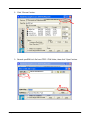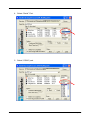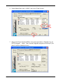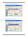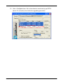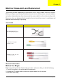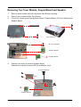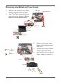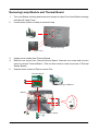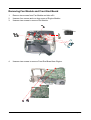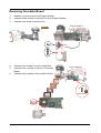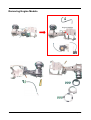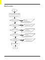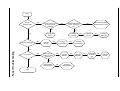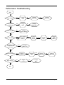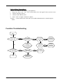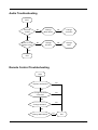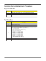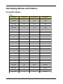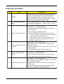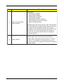
1
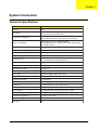
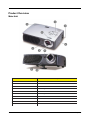
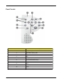
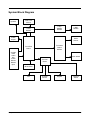
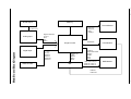
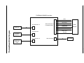
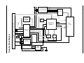
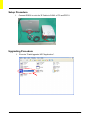
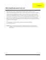
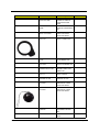
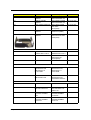
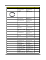
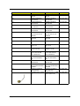
Acer PD721 Service Guide Service guide files and updates are available on the CSD web; for more information, please refer to http://csd.acer.com.tw Service CD P/N: N/A Revision History Please refer to the table below for the updates made on Acer Altos PD721 service guide. Date II Chapter Updates Copyright Copyright © 2001 by Acer Incorporated. All rights reserved. No part of this publication may be reproduced, transmitted, transcribed, stored in a retrieval system, or translated into any language or computer language, i in any form or by any means, electronic, mechanical, magnetic, optical, chemical, manual or otherwise, without the prior written permission of Acer Incorporated. Disclaimer The information in this guide is subject to change without notice. Acer Incorporated makes no representations or warranties, either expressed or implied, with respect to the contents hereof and specifically disclaims any warranties of merchantability or fitness for any particular purpose. Any Acer Incorporated software described in this manual is sold or licensed "as is". Should the programs prove defective following their purchase, the buyer (and not Acer Incorporated, its distributor, or its dealer) assumes the entire cost of all necessary servicing, repair, and any incidental or consequential damages resulting from any defect in the software. Acer is a registered trademark of Acer Corporation. Intel is a registered trademark of Intel Corporation. Pentium and Pentium II/III are trademarks of Intel Corporation. Other brand and product names are trademarks and/or registered trademarks of their respective holders. III Conventions The following conventions are used in this manual : IV Screen messages Denotes actual messages that appear on screen. NOTE Gives bits and pieces of additional information related to the current topic. WARNING Alerts you to any damage that might result from doing or not doing specific actions. CAUTION Gives precautionary measures to avoid possible hardware or software problems. IMPORTANT Reminds you to do specific actions relevant to the accomplishment of procedures. Preface Before using this information and the product it supports, please read the following general information. 1. This Service Guide provides you with all technical information relating to the BASIC CONFIGURATION decided for Acer's "global" product offering. To better fit local market requirements and enhance product competitiveness, your regional office MAY have decided to extend the functionality of a machine (e.g. add-on card, modem, or extra memory capability). These LOCALIZED FEATURES will NOT be covered in this generic service guide. In such cases, please contact your regional offices or the responsible personnel/channel to provide you with further technical details. 2. Please note WHEN ORDERING FRU PARTS, that you should check the most up-to-date information available on your regional web or channel. If, for whatever reason, a part number change is made, it will not be noted in the printed Service Guide. For ACER-AUTHORIZED SERVICE PROVIDERS, your Acer office may have a DIFFERENT part number code to those given in the FRU list of this printed Service Guide. You MUST use the list provided by your regional Acer office to order FRU parts for repair and service of customer machines. V VI Table of Contents Chapter 1 System Introduction........................................................................... 1 Technical Specification................................................................................................. 1 Product Overview......................................................................................................... 3 System Block Diagram............................................................................................... 6 Chapter 2 Firmware Upgrade.............................................................................. 10 Setup Procedure.................................................................................................. 11 Upgrading Procedure............................................................................................ 11 Chapter 3 Machine Disassembly and Replacement................................................ 17 Tool Needed......................................................................................................... 17 General Information.............................................................................................. 17 Removing Top Cover Module, Keypad Board and Speaker........................................ 18 Removing AV Module and Connector Board............................................................ 20 Removing Lamp Ballast and Power Supply..............................................................21 Removing Lamp Module and Thermal Board............................................................ 22 Removing Fan Module and Front End Board............................................................23 Removing Formatter Board.................................................................................... 24 Removing Engine Module...................................................................................... 25 Chapter 4 Troubleshooting........................................................................................... 26 Equipment Needed.............................................................................................. 26 Main Procedure.......................................................................................... 27 Power Troubleshooting................................................................................ 28 Performance Troubleshooting.......................................................................29 Function Troubleshooting............................................................................ 30 Audio Troubleshooting.................................................................................31 Remote Control Troubleshooting.................................................................. 31 Function Test and Alignment Procedure................................................................ 32 Equipment Needed.................................................................................... 32 Test Condition...........................................................................................32 Test Display Modes and Patterns......................................................................... 33 Compatible Modes.................................................................................... 33 Function Test Display Pattern.................................................................... 35 Inspection Procedure......................................................................................... 37 Chapter 5 FRU (Field Replaceable Unit) List ...................................................... 39 i Chapter 1 System Introduction Technical Specification Item 1 Description Display DLPTM Resolution Native XGA (1024x768), SXGA (1280x1024) compressed Computer Compatibility IBM PC and Compatibles, Apple Macintoash, iMac, and VESA Standards SXGA, XGA, SVGA, VGA(resizing) Video Compatibility NTSC M(3.58/4.43), PAL (B/D/G/H/I/M/N), SECAM(B/D/G/K/K1/L), HDTV(720p, 1080i), EDTV(480p), SDTV(480i), 576i/p Aspect Ratio 4 : 3 Native, 5 : 4 / 16 : 9 Compatible Contrast Ratio (Typical) 2000 : 1 Displayable Colors 16.7 Million Colors Brightness (Typical) 2,300 ANSI Lumens Projection Lens F / 2.44~2.69, f=28.8~34.5mm 1 : 1.12 Manual Zoom and Manual Focus Projection Screen Size (Diagonal) 23" (0.58m)~246"(6.25m) Projection Distance 3.74' (1.14m)~32.8' (10m) Horizontal Scan Rate 15~100 kHz Vertical Refresh Scan Rate 43~120 Hz Lamp Type 250W User Replaceable UHP Lamp Lamp Life 2,000 Hours Keystone Correction +/-16 Degrees Weight 6.6 lbs (3kg) Dimension 277 x 225 x 85mm (10.9" x 8.9" x 3.3") Remote Mouse Control Remote Control with Mouse Function & Laser Pointer Power Supply AC Input 100-240V auto-switching power supply Power Consumption 320 Watts Operation Temperature 5oC~35oC / 41oF~95oF Noise Level (Typical) 32 dB in Normal Operation Uniformity 90% Chapter 1 Item Description Computer Input - 1 HDB 15-Pin D-Sub (VGA/Component/HDTV input port) - 1 DVI Connector - 2 Audio Mini Jack (1 for 15-pin D-SUB, 1 for DVI) I/O Connectors AV Input - 1 Mini DIN for S-Video Input Connector - 1 RCA Jack for Composite Video Input Connector - 1 Audio Mini Jack for S-Video/Composite Video Output - 1 Mini D-SUB 15-Pin for Monitor Loop Through - 1 Audio Mini Jack for monitor loop through - 1 Remote Mouse Port AC Power Cord 15-Pin VGA Signal Cable (1.8M) RCA Composite/HDTV Video Cable S-Video Signal Cable Wireless Remote Control with mouse function and laser pointer Standard Accessories AA Tu[e Batteroes X 2 for remote multi-language user's guide (CD-ROM) multi-language quick start card lens cap soft carrying bag Audio cable jack/RCA Y cable for remote control (support USB/Com port) Chapter 1 2 Product Overview Main Unit Item 3 Description 1 Panel Control 2 Power Connector Power Switch 3 Connection Ports 4 Focus Ring 5 Zoom Lens 6 Zoom Ring 7 S p e a ke r 8 Remote Control Receiver 9 Elevator Button 10 Elevator Foot Chapter 1 Panel Control Item Chapter 1 Description 1 Lamp Warning LED 2 Temperature Warning LED 3 Volume 4 Mute 5 Menu (On/Off) 6 Four Directional Select Keys 7 Enter 8 Zoom 9 Re-sync 10 Source 11 Power / Standby 4 Connection Ports Item 5 Description 1 RS232 Input Connector 2 Audio Input for Video 3 Composite Video Input Connector 4 S-Video Input Connector 5 Audio Input for DVI 6 DVI Input Connector 7 Audio Input for Computer 8 PC Analog Signal / HDTV / Component Video Connector 9 Audio Output Connector 10 Monitor Loop-through Connector 11 Remote Mouse Input Connector 12 Power Switch 13 Power Connector Chapter 1 System Block Diagram Speaker Inter Lock Switch Lamp Ballast Module LVPS Module D-Sub Output LAMP Module Photo Sensor Formatter Board Module Front-End Board S-Video Video Audio DVI D-Sub Mouse RS232 Input Color Wheel Thermal Board IR Receiver Fan Chapter 1 Thermal Sensor Keypad Thermal Switch 6 Chapter 1 Memory D-Sub output Thermal Board KDS (0-3) KDR (0-2) ERR Standby-1 R.G.B.H.Vsync Digital R.G.B data H.Vsync SDA SCL GCLK Image Process Main Board Block Diagram Digital Input Video Decoder y (0-7) UV (0-7) GM-VHS GM-VVS GM-VPEN GM-VCLK Standby out 7 Sec RESET MCLK DCLK MIS ECOMODE LVPS Module LAMP Lit Digital R.G.B Data DCLK0 DENR DVS DHS LAMP ON / Lamp Lit RESET# / Lamp Lit RESET0 / Lamp Lit DMD Module LAMP-IN LAMP-OUT 7 Analog Input 8 THERMAL BOARD Interface STB ECON KEY 7PIN 3P Connector *4 20P Connector to Formatter Board MAIN BOARD LAMPMISS POWER 15V, 5VA STANDBY ERR_OUT IR_ON 2P Connector THERMAL SWITCH 4P Connector *2 16P Connector KEY PAD THERMAL SENSOR LM75 Chapter 1 Thermal Board Block Diagram FAN 1-4 ERR_OUT Chapter 1 +5V +12V VCC2 (DMD) VCC2 (ASIC) VOFFSET VCC2,VOFFSET,VBIAS VERSET GENERATION VBIAS VRESET RESET ASIC MBIASRST (16) DATA (8) FPGA CLK DATAPATH FORMATTER DPF2A DPF2A CONTROL INPUTCLK VOLTAGE ENABLES BIAS BIN BIAS/RESET CONTROL DMD CONTROL PBUS2 FPGA CLK VSYNCZ DMD CLK SDRAM CLK DMD DATA(0..63) DMD 0.7” XGA DATA(0..63) MENORY CONTROL A HSYNCZ CONTROL FPGA ACTDATA TFIELD MENORY MENORY ADDRESS ADDRESS A(12) A(12) MENORY ADDRESS B(12) OLACT MENORY CONTROL B SYNCVAL DMD CONTROL LAMP CONTROL&STATUS CWRSTZ COLOR WHEEL INDEX SDRAM A SDRAM B VSYNCZ, RESETZ FLASH PROGRAMMING HEADER IIC BUS HITACHI DOWNLOAD HEADER MICRO CONTROLLER CLKIN COLOR WHEEL CONTROL ALLEGRO MOTOR CONTROL COLOR WHEEL STATUS COLOR WHEEL DRIVE 9 CUSTOMER INTERFACE CONNECTOR Formatter Block Diagram CLOCK OSC ADDRESS (19) CONFIG/ SEQUENCE PROM Chapter 2 Firmware Upgrade This chapter provides the equipment needed, setup and upgrading procedure for Firmware upgrade. Equipment Needed Item Description Bootcode.axe Bootcode.hex Configdata.hex Gui.hex RomCode.axe Software Flasher.hex pwSDK.inf ChkSum.txt Flasher.hex DISPSUM.exe FlashUpgrader MFC Application Fixture : - Cable RS-232 (Blue To Mini Din 3PIN 1800mm) (P/N : 42.86301.001, Rev.A) Hardware PC PD721 Projector Chapter 2 10 Setup Procedure 1. Connect RS232 to mini din 3P Cable to COM1 of PC and PD721. COM1 DFP Port Upgrading Procedure 1. 11 Execute “FlashUpgrader MFC Application”. Chapter 2 2. Click “Choose” button. PD721-V05-2002.08.13\ 3. Search <pwSDK.inf> file from PD721 F/W folder, then click “Open” button. PD721-V05-2002.08.13 1 2 Chapter 2 12 4. Select “Serial” Port. PD721-V05-2002.08.13 5. Select “COM1” port. PD721-V05-2002.08.13 13 Chapter 2 6. Select Baud Rate to be “115200”, then click “Flash” button. PD721-V05-2002.08.13 1 2 7. Plug in the Power Cord to PD721, then press and hold on “Standby” key on PD721 keypad (Note : The Firmware upgrade program will be stop if you havn’t hold the standby button.) PD721-V05-2002.08.13 Chapter 2 14 8. Downloading <Flasher.hex> and <Gui.hex> files. PD721-V05-2002.08.13 9. Keep on downloading <RomCode.hex> file. PD721-V05-2002.08.13 15 Chapter 2 10. After <Configdata.hex> file is downloaded, await starting up PD721 (about 2-3 seconds), then finish the upgrading procedure. PD721-V05-2002.08.13 Chapter 2 16 Chapter 3 Machine Disassembly and Replacement This section provides disassembly procedures for PD721 Micro Portable XGA DLP Projector. Before you begin any of these procedures, be sure to turn off the power, computer system, and other attached devices; then disconnect the power cable from the electronically outlet. Moreover, when you disassemble the projector, be sure to put the screws in a safe place and separate them according to grouping. Tool Needed Item PHOTO Long Nose Nipper (Left) Angle Cutting Nipper (Right) Hex Sleeves 5mm (Top) Screw Bit (-) 101 Screw Bit (+) : 107, 102, 101 (from top to bottom) General Information Before You Begin Before proceeding with the disassembly procedure, make sure that you do the following: 1. Turn off the power to the system and all peripherals. 2. Unplug the AC adapter and all power and signal cables from the system. 3. Anti-static wrist strap. 17 Chapter 3 Removing Top Cover Module, Keypad Board and Speaker 1. 2. 3. Remove three screws and one long screw from Bottom Housing. Remove four screws beside Top Housing. Lift up Top Housing and unplug three wires to Thermal Board, IR Cover Module and Speaker Board. Top Housing Bottom Housing IR Cover Module Speaker Board Keypad Board 4. Unscrew one screw to remove Speaker Board Unscrew four screws to remove IR Cover Module, Vent. IR Cover Module Vent Speaker Board Chapter 3 18 5. Tear off Keypad Light Insulator, then remove four screws of Keypad Board and tear off 3M Tape then unscrew two screws of Speaker Holders to remove speaker. Speaker Rubber Left Speaker Keypad Board Speaker Holder Tape 3M J350 17*60mm Speaker Rubber Right Keypad Light Insulator 19 Chapter 3 Removing AV Module and Connector Board 1. 2. Turn over Bottom Housing and remove four screws from Bottom Housing. Unscrew two screws of Label Connector Module to remove Label Connector Module and remove two screws from Connector Cover Clamp. Take off Side Vent. Connector Cover Clamp Bottom Housing Side Vent 3. 4. Remove two screws and four long screws from Label Connector Module. Unscrew four screws of Connector Board to remove it. Connector Board Connector Board Label Connector Module Chapter 3 20 Removing Lamp Ballast and Power Supply 1. 2. 3M Tape Remove two screws from Lamp Housing. Unplug one wire to Lamp. Tear of 3M Tape, unplug three wires and unscrew four screws of Ballast Bracket to remove Ballast Module. Lamp Housing Lamp Ballast Insulator Ballast Bracket 3. 4. Power 5. Remove two screws from Power Socket Bracket and take off it. Loosen one screw of Power supply from grounding. Unscrew four hex screws of Power Supply to remove it. Power Insulator 21 Chapter 3 Removing Lamp Module and Thermal Board 1. 2. Turn over Bottom Housing and loosen two screws of Lamp Cover from Bottom Housing and take off Lamp Cover. Loosen three screws of Lamp to remove Lamp. Lamp Bottom Housing Lamp Cover 3. 4. 5. Unplug seven cables from Thermal Board. Remove one screw from Thermal Sensor Board. Unscrew one screw and one hex screw to remove Thermal Board. (The one hex screw is under one screw of Thermal Sensor Board) Unscrew three screws of Fan to remove Fan. Thermal Board Engine Module Bracket Fan Thermal Sensor Board Chapter 3 22 Removing Fan Module and Front End Board 1. 2. 3. Remove two screws from Fan Module and take off it. Unscrew four screws and one long screw of Engine Module. Unscrew two screws to remove Fan Module. Fan 4. Unscrew two screws to remove Front End Board from Engine. Front End Board 23 Chapter 3 Removing Formatter Board 1. 2. 3. Unscrew one hex screw from Engine Module. Unscrew three screws to remove Fan from Engine Module. Unscrew one screw to remove Fan. Engine Module Fan 4. 5. 6. Unscrew two screws to remove Heat Sink. Unscrew four screws to remove Formatter Board. Unscrew two screws to remove Safe Switch. Engine Module Safe Switch Formatter Board Heat Sink Chapter 3 24 Removing Engine Module Engine Module 25 Chapter 3 Chapter 4 Troubleshooting This chapter provides technicians and people who have an electronic background a primary description about maintaining the product. Moreover, you can get the appropriate operation to solve some complicated problems of component repairing and professional problems. The Troubleshooing section focus on below items: 1. Power Troubleshooing 2. Performance Troubleshooting 3. Function Troubleshooting 4. Audio Troubleshooting 5. Remote Control Troubleshooting Equipment Needed Item PD721 Projector VESA M1 to VGA Cable PC (Personal Computer) Audio Input, Video Input Screw Drivers Chapter 4 26 Main Procedure Start Connect Power cord, analog or digital signal and audio signal, then turn power on Is Lamp light on ? No A. Power Troubleshooting Yes Is Image OK ? No B. Image Performance Troubleshooting Yes Is function OK? No C. Function Troubleshooting Yes Is Audio OK? No D. Audio Troubleshooting Yes Is Remote Control OK? No E. Remote Control Troubleshooting Yes No Fault Found End 27 Chapter 4 28 Start Is LED indicator OK? No Check power cord & input power voltage Yes No Yes Is Fan working? Yes Supply AC Power No Change DC-DC Reassembly lamp Replacement Cover No Lamp Replacement Cover assembly OK? No Change Ballast Change Thermal BD No No Change DC-DC No Change Main BD Change Fan Module Is Lamp lit? Yes No Can hear the sound of lamp ignition Change Ballast No Change Main BD No Change Thermal BD No Change DC-DC Yes Reassembly Lamp Module End No No Replace Lamp Module Chapter 4 Power Troubleshooting Yes Performance Troubleshooting Start Have image? No Change M/B No Change DMD Board Yes Change M/B No Change DMD Board Change DMD CHIP No Yes Have garbage pattern? No Uniformity OK? Change Engine Module No Yes Is color OK? Color Adjust No Procedure * Note 1 No Change Photo Sensor No No Change M/B Change DMD Board Yes Dot defect isnt compliant with the spec.? Yes Change DMD CHIP No Have line bar? Yes Adjust frequency No Change M/B No Change DMD Board No Change DMD CHIP No Have noise? Yes Adjust tracking No Change M/B No End 29 Chapter 4 Color Adjust Procedure : * Notice : PC shall run R.G.B. gray scale pattern. 1. Power on. Press Up, Up, Left button when the No Signal show on the screen. 2. Choose Display Source 3. Choose Color Wheel Index. 4. Press Left or Right button to adjust. 4Note 1 : It may need to be used when you replace Main Board or Optical Engine alone. Function Troubleshooting Start Does OSD show up? No Is KeyPad Board OK? Yes No Can function be adjusted? Yes End Chapter 4 No Is Keypad Board ok? Yes Change Main Board No Change Remote Controller No Change Key Pad Board Yes Is Remote Controller OK? Change Battery Yes Change Main Board No Change Keypad Board 30 Audio Troubleshooting Start Can hear sound? No Change Main Board No Change Spearker No Change Speaker No Change M/B Yes Sound is clear without noise? Yes End Remote Control Troubleshooting Start Yes Replace the battery No Yes Change Remote Controller No Yes Change IR Board No Change Main Board 31 Yes End Chapter 4 Function Test and Alignment Procedure Equipment Needed Item Description 1 IBM PC with XGA resolution (Color Video Signal & Pattern Generator) 2 VCR with Multi-system (NTSC/PAL/SECAM) 3 Chroma meter Minolta CL-100 4 Hi-Pot Test Condition Item Chapter 4 Description 1 Circumstance Brightness : Dark room less than 60 lux 2 Inspection Distance : 2.0m 3 Screen Size : 60 inches diagonal (wide) 4 Before function test and alignment, each PD721 should be run-in and warmedup for at least 30 minutes with following conditions. 1.) In room temperature 2.) With cycled display colors (R,G,B,White) 3.) With cycled display modes 640*350 (H=31.5 KHz, V=70 Hz) 640*400 (H=31.5 KHz, V=70 Hz) 640*480 (H=37.5 KHz, V=75 Hz) 720*400 (H=31.5 KHz, V=70 Hz) 800*600 (H=53.7 KHz, V=85 Hz) 800*600 (H=37.9 KHz, V=60 Hz) 1024*768 (H=48.4 KHz, V=60 Hz) 1024*768 (H=68.7 KHz, V=85 Hz) 5 Test Display Mode & Pattern 6 Function Test and Alignment Procedure 32 Test Display Modes and Patterns Compatible Modes Analog : 33 Resolution V-Sync(Hz ) H-Sync(KHz ) Compatibility 640 x 350 70 31.5 VGA 640 x 350 85 37.9 VGA 640 x 400 70 31.5 VGA 640 x 400 85 37.9 VGA 640 x 480 60 31.5 VGA 640 x 480 72 37.9 VGA 640 x 480 75 37.5 VGA 640 x 480 85 43.3 VGA 720 x 400 70 31.5 VGA 720 x 400 85 37.9 VGA 800 x 600 56 35.2 SVGA 800 x 600 60 37.9 SVGA 800 x 600 72 48.1 SVGA 800 x 600 75 46.9 SVGA 800 x 600 85 53.7 SVGA 1024 x 768 43.4 35.5 XGA 1024 x 768 60 48.4 XGA 1024 x 768 70 56.5 XGA 1024 x 768 75 60.0 XGA 1024 x768 85 68.7 XGA 640 x 480 66.66 34.98 MAC LC 13" 640 x 480 66.68 35 MAC II 13" 832 x 624 74.55 49.725 MAC 16" 1024 x 768 75 60.24 MAC 19" 1152 x 870 75.06 68.68 MAC 640 x 480 60 31.35 MAC G4 640 x 480 120 68.03 MAC G4 1024 x 768 120 97.09 MAC G4 640 x 480 117 60 i Mac DV 800 x 600 95 60 i Mac DV 1024 x 768 75 60 i Mac DV Chapter 4 Digital : Chapter 4 Resolution V-Sync(Hz ) H-Sync(KHz ) Compatibility 640 x 350 70 31.5 VGA 640 x 350 85 37.9 VGA 640 x 400 70 31.5 VGA 640 x 400 85 37.9 VGA 640 x 480 60 31.5 VGA 640 x 480 72 37.9 VGA 640 x 480 75 37.5 VGA 640 x 480 85 43.3 VGA 720 x 400 70 31.5 VGA 720 x 400 85 37.9 VGA 800 x 600 56 35.2 SVGA 800 x 600 60 37.9 SVGA 800 x 600 72 48.1 SVGA 800 x 600 75 46.9 SVGA 800 x 600 85 53.7 SVGA 1024 x 768 43 35.5 XGA 1024 x 768 60 48.4 XGA 1024 x 768 70 56.5 XGA 1024 x 768 75 60.0 XGA 34 Function Test Display Pattern Item Test Content 1 Frequency & Tracking 2 Pattern Fine Line Moire Remark Eliminate visual wavy noise. Figure 1 Contrast/BrightneGray Scale ss Gray levels should be distinguishable. Figure 2 3 R, G, B and White R, G, B and Color White Color Performance Each R, G, B color should be normal. Figure 3~6 4 Screen Uniformity & Flicker Full White Should be compliant with the spec. Figure 6 5 Dead/Blemish Pixel R, G, B, White, The numbers of dead/blemish Dark, Blue pixels should be compliant with the 180, Gray 30 sp e c. Boundary Boundary Frame 6 Fine Line Morie Pattern (Figure 1) R. Color Pattern (Figure 3) 35 Specification Figure 3~9 Horz. and Vert. position of video Figure shuld be adjustable to be within the 10 screen frame. Contrast & Brightness (Figure 2) G. Color Pattern (Figure 4) Chapter 4 B. Color Pattern (Figure 5) Dark Pattern (Figure 7) Blue 180 Pattern (Figure 9) Chapter 4 Full White Pattern (Figure 6) Gary 30 Pattern (Figure 8) Boundary Frame (Figure 10) 36 Inspection Procedure N o. Description 1 RESET Please press "Menu" button on the projector panel to enter "Factory Reset" Function then choose "YES" and press "Enter" to see if it works. This action will allow you to erase all end-user's settings and restore the original factory setting. 2 Hi-Pot and Grounding Test - Hi-Pot Specification : 1.5kVAC, 10mA, 2 seconds. - Grounding Specification : 12VDC, 25A, 0.1 ohm. Clock and Clock Phase Test Signal : 1024*768 @ 85Hz Test Pattern : Line Moire Pattern - Check and see if image sharpness and focus is well performed. - If not, readjust by following steps. 1.) Enter "Digital Conversion" menu and select "Clock" Function to adjust the total pixel number of pixel clock in one line period. 2.) Then select "Clock Phase" Function and use right or left arrow key to adjust the value to minimize video flicker. 4 R, G, B and White Colors Contrast Test Signal : 1024*768 @ 85Hz Test Pattern : 64 or 16 R, G, B and White colors Intensities Pattern - Please check and see if each colors is normal and distinguishable. - If not, please return the unit to repair area. 5 Screen Uniformity and Flicker Test Signal : 1024*768 @ 85Hz Test Pattern : Full White Pattern - Please check and see if it's in normal condition. - If not, please return the unit to repair area. Dead Pixel/Blemish Pixel Test Signal : 1024*768 @ 85Hz Test Pattern : Gray 30, Blue 180, White, Dark, Red, Green and Blue Pattern - Please check and see if there are dead pixels on DMD chip. - The total numbers and distance of dead pixels should be complaint with specification. 3 6 37 Item Chapter 4 N o. 7 Item Check for Secondary Display Modes Description Test signal : - 640*350 @ 70/85Hz - 640*400 @ 70/85Hz - 640*480 @ 72/75/85Hz - 720*400 @ 70/85Hz - 800*600 @ 56/60/72/75/85Hz - 1024*768 @ 43.4/60/70/75/85Hz - 1280*1024 @ 60/75Hz Normally when the primary mode 1024*768 @ 85Hz is well adjusted and complaint with the specification, then the secondary display modes will be great possibility to be complaint with the specification. But we still have to check with general test pattern to make sure every secondary modes is complaint with specification. 8 Chapter 4 Factory Reset After final QC step, we have to erase all saved change again and restore the factory defaults. Please select and enter "Factory Reset " Function to see if it is workable. This action will allow you erase all end-user's settings and restore the original factory setting. 38 Chapter 5 FRU (Field Replaceable Unit) List This chapter gives you FRU ( Field Replaceable Unit ) listing in global configuration of PD721. Refer to this chapter whenever ordering for parts to repair or for RMA ( Return Merchandise Authorization ). Please note that WHEN ORDERING FRU PARTS, you should check the most up-to-date information available on your regional web or channel. For whatever reasons a part number change is made, it will not be noted on the printed Service Guide. For ACER AUTHORIZED SERVICE PROVIDERS, your Acer office may have a DIFFERENT part number code from those given in the FRU list of this printed Service Guide. You MUST use the local FRU list provided by your regional Acer office to order FRU parts for repair and service of customer machines. You might be able to access the website to obtain the latest spare parts information: http://aicsl.acer.com.tw/spl/ NOTE: To scrap or to return the defective parts, you should follow the local government ordinance or regulations on how to dispose it properly, or follow the rules set by your regional Acer office on how to return it. Chapter 5 39 FRU List Photo Part Name Description P/N ACCESSORY N/A REMOTE CONTROLLER ACCESSORY REMOTE CONNTROLLER EZPRO 735(NEUTRAL) 25.320VH.001 N/A BAG W/CUSHION INSIDE SOFT CASE SOFT CARRY BAG FOR 47.720VH.014 ACER PD720 N/A PCBA THERMAL SENSOR BOARD PCBA THERMAL SENSOR BD EZPRO 730/735 ID=91 55.310VH.009 N/A PCBA MAIN BOARD ASSY PCBA MAIN BOARD EP755 FOR ACER (PD720) 55.721VH.001 N/A PCBA THERMAL BOARD EZPRO 755/ H55 FOR SUNON PCBA THERMAL BOARD EZPRO 755/ H55 FOR SUNON 55.721VH.002 N/A PCBA CONNECTOR-AV BOARD PCBA CONNECTOR-AV BOARD EP757 55.721VH.003 N/A PCBA DMD-BOARD PCBA DMD BOARD EP757 55.721VH.004 PCBA KEYPAD BOARD PCBA KEYPAD BOARD EzPro 755 55.720VH.006 PCBA SPEAKER BOARD PCBA SPEAKER BOARD EzPro 755 55.720VH.007 BOARD N/A 40 PCBA THERMAL PCBA THERMAL SENSOR BOARD ID=90 SENSOR BOARD EzPro 755 ID=90 55.720VH.008 PCBA IR-SENSOR BOARD 55.720VH.009 PCBA IR-SENSOR BOARD CALLAS Chapter 5 Photo Part Name Description P/N CABLES N/A Y CABLE MINI DIN 8P TO USB “A” TYPE/DSUB 1.8M Y CABLE MINI DIN 8P TO USB “A” TYPE/DSUB 1.8M CARUSO 50.720VH.001 N/A CABLE W.A 24PIN 2.0P W.A 24PIN 2.0P 324 EZPRO 755 50.720VH.002 IR FRONT CABLE W.A 3P W.A 3P#26 IR FRONT EzPro 755 50.720VH.003 N/A CABLE W.A 4PIN 2.0P W.A 4PIN 2.0P 326 EZPRO 755 50.720VH.004 N/A LVPS-BALLAST POWER W.A 2PIN #20 LVPSCABLE W.A 2PIN BALLAST POWER EZPRO 755 50.720VH.005 IR BACK W.A 3P W.A 3P #26 IR BACK EzPro 755 50.720VH.006 FFC CABLE 16P 0.5MM L=20CM CABLE FFC 16P 0.5MM L=20CM EP755 50.720VH.007 BALLAST TO LVPS CABLE W.A 5PIN 1.0P W.A 5PIN 1.0P #28 BALLAST TO LVPS EP755 50.720VH.008 FFC CABLE 10PIN PITCH=1.0 L=100MM CABLE FFC 10PIN PITCH=1.0 L=100MM EP755 50.720VH.009 N/A Chapter 5 41 Photo Part Name Description P/N N/A ENGINE TO HEAT SINK WIRE 22AWG W.A ENGINE TO HEAT SINK EMI WIRE 22AWG EP757 50.721VH.001 N/A LPP TO VIDEO CABLE 1500MM CABLE RCA 1500MM LPP-VIDEO 50.310VH.006 N/A S-VHS CABLE 2M CABLE S-VHS 2M EZPRO 600 50.310VH.007 N/A VGA CABLE 15P 1.8M 3C+5 BLACK CABLE VGA 15P 1.8M 3C+5 BLACK 50.321VH.005 N/A MINI JACK TO RCA CABLE 1800MM CABLE MINI JACK TO RCA 1800MM 50.721VH.002 N/A DVI TO VGA CABLE 1.8M CABLE DVI(WHITE)TO VGA (BLUE) 1.8M EZPRO 735 50.320VH.007 N/A POWER CORD 1830MM(EUROPE) CABLE POWER CORD 1830MM SP30+IS14 (EUROPE) 27.720VH.001 N/A POWER CORD 1830MM CABLE PWOER CORD EUR.(UK) 1830MM SP-023+IS14 EUR.(UK) 27.720VH.003 N/A POWER CORD 1800MM CABLE PWOER CORD BLACK (SWISS) AC 6FT BLACK (SWITZERLAND)FOR ACER 27.720VH.005 N/A POWER CORD 1830MM CABLE POWER CORD (US,TWN) 1830MM SP30+IS14 (US,TWN) 27.720VH.002 N/A POWER CORD 1800MM CABLE POWER CORD (AUSTRALIA) 1800MM (AUSTRALIA) 27.721VH.001 N/A POWER CORD 2000MM(CHINA) CABLE POWER CORD 2M 220V (CHINA) 27.720VH.004 IR COVER BACK IR COVER BACK PC RED EzPro 755 42.720VH.001 IR COVER FRONT IR COVER FRONT PC RED EZPRO 755 42.720VH.002 CASE/COVER/BRACLET ASSEMBLY N/A 42 Chapter 5 Photo Part Name Description P/N ZOOM RING BASE PC+ABS ZOOM RING BASE PC+ABS EzPro 755 42.720VH.003 FOCUS RING PC+ABS CS-CT52A FOCUS RING PC+ABS CS-CT52A, 53A EP755 FOR ACER 42.720VH.004 FRONT COVER PC+ABS CS-CT52A FRONT COVER PC+ABS CS-CT52A EP755 FOR ACER 42.720VH.005 CONNECTOR COVER CLAMP CONNECTOR COVER CLAMP PC+ABS EZPRO 755 42.720VH.006 SIDE VENT PC+ABS SDIE VENT PC+ABS EzPro 755 42.720VH.007 KEYPAD PC+ABS HIGHT GLOSSY KEYPAD PC+ABS HIGHT GLOSSY EP755 FOR ACER 42.720VH.008 N/A LED LENS PC CLEAR SINGLE LED LENS PC CLEAR SINGLE EZPRO 755 42.720VH.009 N/A LED LENS PC CLEAR TWIN LED LENS PC CLEAR TWIN EZPRO 755 42.720VH.010 Chapter 5 43 Photo 44 Part Name Description P/N N/A CONNECTOR AV COVER PC+ABS CONNECTOR AV COVER PC+ABS CSCT53A EP755 FOR ACER 42.720VH.011 N/A THERMAL BOARD STAND THERMAL BOARD 42.720VH.012 STAND PC+ABS EZPRO 755 N/A FAN GUIDE FRONT NORYL CS-CT52A FAN GUIDER FRONT NORYL CS-CT52A EP755 FOR ACER 42.721VH.001 SPEAKER HOLDER SECC 1.0t SPEAKER HOLDER SECC 1.0t EzPro 610 42.720VH.013 N/A AXIAL FAN BRACKET AL0.8T AXIAL FAN BRACKET AL0.8T EZPRO 755 33.720VH.001 N/A BALLAST BRACKET SECC 0.8T BLLAST BRACKET SECC 0.8T EZPRO 755 33.720VH.002 N/A POWER SOCKET BRACKET SECC 0.8T POWER SOCKET BRACKET SECC 0.8T EZPRO 755 33.720VH.003 N/A DMD FAN GUIDE PLATE DMD FAN GUIDE PLATE 33.721VH.001 SECC 1T SECC 1T EP757 N/A MAIN BOARD EMI SHELTER AL H56 MAIN BOARD EMI SHELTER AL H56 33.721VH.002 N/A ELEVATOR MODULE CS-CT53A BUY ASSY ELEVATOR MODULE CS-CT53A EP755 FOR ACER 42.721VH.002 LENS CAP MODULE CS-CT52A BUY LENS CAP MODULE CS-CT52A EP755 FOR ACER 42.720VH.015 N/A DMD CONTACT HOUSING CONTACT HOUSING FOXCONN FOR DDR XGA 42.721VH.003 N/A LVPS ASSY ASSY LVPS QUASAR EP757 42.721VH.004 Chapter 5 Photo Part Name Description P/N N/A BACK IR COVER MODULE ASSY BACK IR COVER MODULE EZPRO 755 42.721VH.005 N/A FRINT IR COVER MODULE ASSY FRONT COVER MODULE EZPRO 755 42.721VH.006 N/A LAMP COVER MODULE ASSY LAMP COVER FOR ACER PD721(RMA) 42.721VH.007 N/A BOTTOM HOUSING MODULE ASSY BTM HSG FOR ACER PD721(RMA) 60.721VH.001 TOP HOUSING MODULE ASSY TOP HOUSING MODULE PD720 FOR ACER (RMA) 60.720VH.002 N/A DMD 0.7 INCH XGA 12 DEGREE SDR TYPE A DMD 0.7 INCH XGA 12 DEGREE SDR TYPE A 57.520VH.001 N/A ENGINE MODULE ASSY ENGINE MODULE EP755 PHILIPS(RMA) 57.721VH.001 N/A LAMP MODULE LAMP MODULE EC.72101.001 N/A SUNON DC BRUSHLESS FAN GM1205PHV1-A 50*50*15MM SUNON DC BRUSHLESS FAN GM1205PHV1-A 50*50*15MM 23.720VH.001 N/A MISC FAN SUNON GM1207PKV3-AR SUNON DC BRUSHLESS FAN GC054006VH-8 EP757 23.721VH.001 DIGITAL LIGHT DEVICE FAN MISCELLANEOUS N/A TAPE 3M J350 17*60MM TAPE 3M J350 17*60MM 47.310VH.003 N/A INSULATOR FOR BALLAST FRPP 0.5T INSULATOR FOR BALLAST FRPP 0.5T EZPRO 755 47.720VH.002 N/A MAIN BOARD SUPPORT RUBBER 5.0T MAIN BOARD SUPPORT RUBBER 5.0T EP755 47.720VH.003 N/A MAIN BOARD SUPPORT RUBBER 5.5*20.5.0T MAIN BOARD SUPPORT RUBBER 5.5*20.5.0T 47.720VH.004 Chapter 5 45 Photo N/A Part Name Description P/N LVPS MODULE SUPPORT RUBBER 15*15*5.0T LVPS MODULE SUPPORT RUBBER 15*15*5.0T 47.720VH.005 ZOOM RING SILICONE RUBBER ZOOM RING SILICONE RUBBER EzPro 755 47.720VH.009 N/A SPEAKER RUBBER INSULATOR LEFT SPEAKER RUBBER INSULATOR LEFT EZPRO 755 47.720VH.010 N/A SPEAKER RUBBER INSULATOR RIGHT SPEAKER RUBBER INSULATOR RIGHT EZPRO 755 47.720VH.011 N/A WASHER-ZN CARUSO WASHER-ZN CARUSO 47.720VH.013 N/A LABEL NAMEPLATE AL ACER LABEL NAMEPLATE AL ACER 47.721.VH.001 N/A KEYPAD LIGHT INSULATOR KEYPAD LIGHT INSULATOR EZPRO 755 47.721VH.002 N/A LAMP COVER LIGHT INSULATOR SILICONE 1.0T LAMP COVER LIGHT INSULATOR SILICONE 1.0T EZPRO 47.721VH.003 N/A CONNECTOR BOARD MYLAR FRPP 0.3T CONNECTOR BOARD MYLAR FRPP 0.3T EZPRO 755 47.721VH.004 N/A INSULATOR FOR LVPS ERPP 0.5T INSULATOR FOR LVPS ERPP 0.5T EZPRO 757 47.721VH.005 N/A SPACER SUPPORTS SPACER SUPPORTS SCB-5 47.721VH.006 N/A HEX I/O 440UNC8H58L7.5 NI HEX I/O 440UNC8H58L7.5NI 86.721VH.001 N/A SCREW HEX L=60MM M3*8 EP755 SCREW HEX L=60MM M3*8 EP755 86.721VH.002 N/A SCREW PAN MECH M3*8-BLACK SCREW PAN MECN M3*8-4BLACK 86.110VH.014 N/A HEX SPACER L=58MM COPPER EZPRO 755 HEX SPACER L=58MM COPPER EZPRO 755 86.721VH.003 N/A HEX SPACER L=40MM COPPER EZPRO 755 HEX SPACER L=40MM COPPER EZPRO 755 86.721VH.004 N/A HEX COPPER SPRING WASHER HEX COPPER SPRING WASHER 86.721VH.005 N/A SCREW I/O STEEL #440UNC*H4*L5.5 NYLOK SCRW I/O STEEL #440UNC*H4*L5.5 NYLOK 86.520VH.006 SCREWS 46 Chapter 5 Photo Part Name Description P/N N/A SCREW PAN MECH M3*4 NI SCREW PAN MECH M3*4 NI 86.320VH.003 N/A SCREW PAN MECH M2*4 BLACK SCREW PAN MECH M2*4 BLACK 86.721VH.006 N/A SCREW PAN MECH M2*5 BLACK SCRWE PAN MECH M2*5 BLACK 86.721VH.007 N/A SCREW PAN MECH M3*12 BLACK SCRWE PAN MECH M3*12 BLACK 86.721VH.008 N/A SCREW CAP MECH M3*6 BLACK SCREW CAP MECH M3*6 BLACK 86.721VH.009 N/A SCREW FLAT MECH M2*3 BLACK NYLOK CARUSO SCREW FLAT MECH M2*3 BLACK NYLOK CARUSO 86.721VH.010 N/A SCREW PAN TAP M2.6*5 NI SCREW PAN TAP M2.6*5 NI 86.721VH.011 N/A SCREW PAN TAP M3*6 SCREW PAN TAP M3*6 86.721VH.012 N/A SCREW FLAT TAP M4.5*11 NI SCREW FLAT TAP M4.5*11 NI 86.721VH.013 N/A SCREW FLAT HEAD TAP M1.7*2.5 NI SCREW FLAT HEAD TAP M1.7*2.5 NI 86.520VH.012 N/A WASHER FLAT 7*3.2*0.25T NYLON WITH ADHESIVE WASHER FLAT 7*3.2*0.25T NYLON WITH ADHESIVE 86.721VH.014 N/A SCREW P/F MECH M3*5 BLACK EZPRO 755 SCREW P/F MECH M3*5 BLACK EZPRO 755 86.720VH.001 N/A SCREW PAN MECH M3*8 BLACK SCREW PAN MECH M3*8 BLACK 86.720VH.002 N/A SCREW PAN MECH SCREW PAN MECH 86.720VH.003 M4*5 COLOR W/TOOTH M4*5 COLOR W/TOOTH WASHER WASHER N/A SCREW FLAT MECH M2.6*6 BLACK SCREW FLAT MECH M2.6*6 BLACK 86.720VH.004 SPEAKER D36 H=19MM SPEAKER D36 H=19MM 86.720VH.005 2W 2W 8 Ω EzPro 755 Chapter 5 47