1
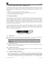
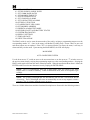
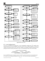
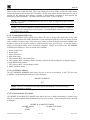
Compact Wireless Controller
Model CXT-N4X and CXT-N7
Integrated Alarm & Control System
Operator’s Installation and Instruction Manual
Covers all Model CXT Control Units
DETCON, Inc.
4055 Technology Forest Bvd. Suite 100,
The Woodlands, Texas 77381
Ph.281.367.4100 / Fax 281.298.2868
www.detcon.com
April 10, 2012 • Document #3756 • Revision 0.0
Model X40
This page left intentionally blank
Shipping Address: 4055 Technology Forest Bvd. Suite 100, The Woodlands Texas 77381
Mailing Address: P.O. Box 8067, The Woodlands Texas 77387-8067
Phone: 888.367.4286, 281.367.4100 • Fax: 281.292.2860 • www.detcon.com • [email protected]
Model X40 Instruction Manual
Rev. 0.0
ii
Model X40
Table of Contents
1.
Introduction............................................................................................................................................1
1.1
1.2
2.
Installation..............................................................................................................................................3
2.1
2.2
2.3
3.
4.
Description ..................................................................................................................................................... 1
System Operation ........................................................................................................................................... 2
NEMA 4 units ................................................................................................................................................ 3
NEMA 7 Units................................................................................................................................................ 4
Initial Start-Up................................................................................................................................................ 5
Secure Digital Card ...............................................................................................................................6
System Operation and Configuration ..................................................................................................7
4.1
Operator Interface........................................................................................................................................... 7
4.1.1
4.1.2
4.1.3
4.1.4
4.2
4.3
5.
6.
7.
PROG Switch ...........................................................................................................................7
“u” Up Arrow Switch..............................................................................................................7
“v” Down Arrow Switch .........................................................................................................7
ENTER and RESET/ACK Switch .............................................................................................7
Normal Operation........................................................................................................................................... 8
Menu Functions.............................................................................................................................................. 8
4.3.1
Auto Configure System...........................................................................................................10
4.3.2
Set # of Channels, AO-4s, RL-4s (Alarm Stations) ................................................................11
4.3.3
Set # of CXT sensors and RXT-320s (Wireless Function Only).............................................11
4.3.4
Set RF Silence and RF Sleep (Wireless Function Only) ........................................................12
4.3.5
Set COMM Baud Rates ..........................................................................................................12
4.3.6
Set Modbus Timeouts .............................................................................................................12
4.3.7
Set Channel Data ...................................................................................................................13
4.3.8
Set Channel Alarms ...............................................................................................................14
4.3.9
Set Low Battery Alarms .........................................................................................................15
4.3.10 Set Relay (Alarm) Functions..................................................................................................15
4.3.11 Flashing Blue LED Codes .....................................................................................................16
4.3.12 Set Modbus Address...............................................................................................................16
4.3.13 Inhibit & Alarm Test Mode....................................................................................................16
4.3.14 RF Link Quality and Battery Status (Wireless Function Only) .............................................17
4.3.15 System Diagnostics ................................................................................................................17
4.3.16 Display Settings .....................................................................................................................18
4.3.17 Time and Date........................................................................................................................18
4.3.18 View TWA & Peak .................................................................................................................19
Troubleshooting Guide........................................................................................................................20
Warranty ..............................................................................................................................................20
Specifications........................................................................................................................................21
7.1
7.2
Spare Parts.................................................................................................................................................... 21
Revision Log ................................................................................................................................................ 22
Table of Figures
Figure 1 Model CXT-N4X Controller .............................................................................................................1
Figure 2 Model CXT-N7 Controller................................................................................................................1
Figure 3 CXT Controller PCA........................................................................................................................2
Model X40 Instruction Manual
Rev. 0.0
iii
Model X40
Figure 4 CXT-N4X Controller Mounting and Dimensional View .................................................................3
Figure 5 CXT-32-N7 Controller ......................................................................................................................4
Figure 6 Model 100 Terminal Board ...............................................................................................................5
Figure 7 Model 100 Terminal Board Rotary Switches....................................................................................5
Figure 8 Magnetic Programming Tool ............................................................................................................7
Figure 9 Front Panel User Interface.................................................................................................................8
Figure 10 Menu Flow Chart...........................................................................................................................10
List of Tables
Error! No table of figures entries found.
Model X40 Instruction Manual
Rev. 0.0
iv
Model X40
This page left intentionally blank
Shipping Address: 4055 Technology Forest Bvd. Suite 100, The Woodlands Texas 77381
Mailing Address: P.O. Box 8067, The Woodlands Texas 77387-8067
Phone: 888.367.4286, 281.367.4100 • Fax: 281.292.2860 • www.detcon.com • [email protected]
Model X40 Instruction Manual
Rev. 0.0
v
Model X40
1.
Introduction
1.1 Description
The Detcon CXT controller is a multi-channel gas detection controller designed to serve as a host monitor
and for a wireless network of up to 32 CXT Sensors and a variety of wireless alarm stations. The CXT
controller, sensors and alarm stations utilize radios based upon the IEEE 802.15.4 standard that operate at
2.4 GHz using DSSS encoding for robustness. These units are designed for low power operation using
Detcon rechargeable battery packs.
The CXT controller utilizes a non-intrusive magnetic interface and displays the real time status of every
sensor on a backlit LCD. Typical sensor status includes channel number, gas concentration, device tag (gas
type) and alarm/fault status. Each channel provides three alarm levels (Alarm 1, Alarm 2 and Alarm 3) and
fault for which the present status can be shown via the front panel LED indicators. Additional features
include Alarm Inhibit, Alarm Reset and Alarm Silence (Acknowledge) functions.
Figure 1 Model CXT-N4X Controller
The CXT controller is available in NEMA 4 and NEMA 7 enclosures. The units come with their own
internal battery power and are self sustaining, with the only invasive procedure being to change or charge
the batteries. NEMA 4 units have an external battery charger that connects via a Cannon Plug on the side
of the unit. NEMA 7 units use a replaceable battery pack that is accessible by removing the cover on the
condulet.
Figure 2 Model CXT-N7 Controller
Model X40 Instruction Manual
Rev. 0.0
Page 1 of 23
Model X40
1.2 System Operation
The heart of the CXT controller is the non-intrusive magnetic interface with backlit LCD display. The
controller communicates with sensors and alarm stations using RS-485 Modbus™ RTU protocol
distributed over a wireless network. The CXT controller includes a wireless transceiver that communicates
directly with Detcon’s CXT sensors and Detcon Wireless Alarm Stations using the RXT-320 Transceivers.
Figure 3 CXT Controller PCA
Alarm values and fault conditions can be field-configurable via the magnetic user interface to cause an
assigned relay output or bank of relay outputs to fire, thus triggering external alarm devices. As gas alarm
or fault conditions clear, the assigned relay or bank of relay outputs will return to their normal states.
NOTE: All relays controlled by the CXT must be remotely mounted with their own
transceiver. These relays are typically part of the wireless alarm stations, but can be RL-4
modules connected to an RXT-320 transceiver.
The CXT controller can be configured for various CXT sensors and wireless alarm stations at the Detcon
factory based on application specific information provided by the customer on the Configuration Form. It
must be verified that the correct quantity and type of sensors have been purchased to support the customer’s
configuration requirements. On the Configuration Form, the customer should supply all site-specific
information:
1)
2)
3)
4)
5)
6)
Number of gas channels
Detcon sensor model number for each channel
Range, units, and gas type for each channel
Alarm level(s) for each gas channel
Device Tag for each channel
Assignment and set-up information for each alarm station or RL-4 module
NOTE: The set-up configuration is fully field-configurable and can be executed by the user in
the field. Refer to section 4 System Operation and Configuration. Modifications to the set-up
configuration are expected to take place at the customer’s site due to requirement changes
and/or system expansions.
Model X40 Instruction Manual
Rev. 0.0
Page 2 of 23
Model X40
2.
Installation
2.1 NEMA 4 units
The CXT-N4X controller is housed in a NEMA 4X water/corrosion proof stainless steel enclosure for
indoor/outdoor use. Securely mount the Model CXT-N4X enclosure per the mounting dimensions
provided in Figure 4 Power is provided by a battery pack. that can be charged by an external battery
charger. No other outside connections or wiring is utilized, as the unit is self contained.
14
Mounting
Bracket
12.00"
10"
4.2"
3.72"
Ø0.27"
12.75"
13.75"
11.0"
Figure 4 CXT-N4X Controller Mounting and Dimensional View
The CXT-N4X controller is battery powered, and thus is self sustaining. An external Battery Charger is
included to charge the internal batteries when needed. The battery charger connects to a cannon plug
provided on the side of the unit. The battery charger is AC powered, and a 100~240VAC 50~60Hz power
source is required for operation.
NOTE: The battery charger is meant to charge the unit’s batteries, and should not be used to
operate the unit for any length of time.
When the unit is turned on by the On/Off switch mounted on the left side of the unit, the unit will begin
normal operation after a brief power-up diagnostic sequence.
Model X40 Instruction Manual
Rev. 0.0
Page 3 of 23
Model X40
2.2 NEMA 7 Units
The Model CXT-32-N7 controller is housed in an explosion proof NEMA 7 enclosure for indoor/outdoor
use and comes neatly packaged and mounted on a mounting plate designed for 2~3” pole mounting.
Securely mount the Model CXT-32-N7 per the mounting dimensions provided in Figure 5. No outside
connections are expected for operation.
24.75"
3.5"
16.75"
Typ.
CXT Controller
8.25" 11"
J-Box w/ Transceiver
and interconnect
terminal board
Intrinsically Safe
Reset Switch.
Figure 5 CXT-32-N7 Controller
The CXT-N7 controller is battery powered, and thus is self sustaining. The battery pack is removable for
charging or replacement with a freshly charged battery pack. With the battery installed, the unit will
automatically begin normal operation after a brief power-up diagnostic sequence.
NOTE: The battery charger is meant to charge the unit’s batteries, and should not be used to
operate the unit for any length of time.
The NEMA 7 CXT Controller utilizes the RXT-320 Transceiver, and the Model 100 Terminal Board. The
Terminal Board is mounted in the condulet/J-Box (See Figure 5). The terminal board includes connector
plugs for the following:
J1 4-Pin Connector – Modbus Out (Wireless Transceiver Option)
J2 6-Pin Header – Wireless Transceiver Programming Header
J3 6-Beau Connector – used for battery operation or display interface dependant on sensor configuration
J4 4-Pin Connector – Modbus In
J5 6-Pin Connector – used for Display interface with battery/wireless configurations
J6 4-Pin Connector – Sensor connections
J7 4-Pin Connector – Auxiliary power in and mA out.
J8 6-Pin Connector – Wireless Transceiver
J9 5-Pin Header – Terminal Board Programming
Model X40 Instruction Manual
Rev. 0.0
Page 4 of 23
Model X40
S
S
E
L
E
R
I
W
V
/
W
︶
V
4
2
D A
N
G
B
︵
︶
2 A D
N
N
I
A M G
R
W
P
7
J
V
4
2
2
W
S
D
A N
G
1
J
B
N
IR
RA
EL
WO
OS
P
2
J
8
J
T
US
OS
E
SL
UE
BR
DI
OW
M
︵
U N
B
/ G
/
W W
SM
SA
E
LR
EG
RO
IR
WP
1 K N
B
N B
/
I /
W W
A
6
J
4
J
1
W
S
V D
4 N
2 G
A
B
R
O
S
N
E
S
N
I
S
U
B
D
O
M
5
J
L A 1
C D P
S S S
2
P
S
1
P
J
MM
RA
ER
TG
O
R
P
R D
W N
P G
Y
A
L
P
S
I
D
9
L
Figure 6 Model 100 Terminal Board
The Model 100 Terminal Board also contains two rotary switches which are used to set the Modbus™
address for the RXT-320 wireless transceiver of the CXT controller. If not already set from the Detcon
factory, set the address to F0h. Access the terminal board and locate the switches shown in Figure 1. The
MSD (most significant digit) ‘F’ is represented by the top rotary switch (closest to the J1 connector) and
the LSD (least significant digit) ‘0’ is represented by the bottom rotary switch (closest to the J2 connector).
Figure 7 Model 100 Terminal Board Rotary Switches
2.3 Initial Start-Up
The CXT controller will power up as soon as power is applied. There is no external power switch on
NEMA 7 units so power is applied when the battery pack is installed. NEMA 4 units have a power
ON/OFF switch located on the left side of the unit, and power is applied when the switch is energized.
When power is applied to the unit, the unit will boot up and display the company name, model, firmware
version and COMM ports available. It will proceed to poll Modbus™ addresses of any attached devices.
The display will show up to 8 channels at one time. The LCD will then refresh and display the next 8
channels and so on until the LCD cycles back to the first 8 channels and repeats the process. This is
considered normal operation.
If a previous configuration does not exist, the user will need to manually configure the network from the
user-interface. After the unit has been configured, the unit will begin normal operation. If the unit has
been configured properly, the unit will display the current status of the devices that it is connected to.
Model X40 Instruction Manual
Rev. 0.0
Page 5 of 23
Model X40
3.
Secure Digital Card
The CXT controller has a feature that allows data logging when a secure digital (SD) memory card is
installed. The SD card must be installed in the SD slot (J9) on the back of the controller’s PCA before the
controller is powered up. The controller will notify the user if a successful installation of the card was
achieved upon power up. The controller will automatically format the card and create the necessary files
for data logging. See section 4.3.18 for more information regarding the data logging feature.
Model X40 Instruction Manual
Rev. 0.0
Page 6 of 23
Model X40
System Operation and Configuration
4.
The setup of the controller is critical for proper operation. Modbus™ addresses must be correct on all the
devices connected to the controller before the controller will acknowledge them. The number of sensors
must be entered into the controller to allow it to communicate with them. Four basic areas need to be
configured:
¾ The number of sensors must be determined before setup begins.
¾ The sensor’s channel information must be configured to match the sensor connected.
¾ Relay modules and banks must be configured.
4.1 Operator Interface
The operator interface of the CXT controller is accomplished via four internal magnetic switches located
above the controller’s backlit LCD display. The four switches offer a non-intrusive interface and allow for
complete configuration of the controller. These switches are labeled: PROG, “u” (Up Arrow), “v” (Down
Arrow) and ENTER. The ENTER switch also doubles as a RESET/ACK switch from the Main Display
only (Not in Menu Mode). With reference to the Menu Flow Chart (See Figure 10), it is easy to learn how
to navigate the menus and make changes.
The magnetic programming tool (See Figure 8) is used to operate the magnetic switches. Switch action is
defined as a momentary contact (hold) on a switch marker (⊗). For momentary contact, the programming
magnet is briefly held on the switch marker (⊗) and then removed. This action will be referred to as a
“swipe” for the remainder of this manual.
Figure 8 Magnetic Programming Tool
4.1.1
PROG Switch
From the Main Display, the PROG switch enters into the Main Menu. Once inside the Main Menu, the
PROG switch acts as an “Escape” switch that moves backwards in the menu flow chart.
NOTE: While in Main Menu mode there are no updates to gas readings and hence no alarms
will take place.
4.1.2
“u” Up Arrow Switch
This switch moves the user up the Main Menu flow chart. It is also used to change selected entries
within menu selections in the upward direction.
4.1.3
“v” Down Arrow Switch
This switch moves the user down the Main Menu flow chart. It is also used to change selected entries
within menu selections in the downward direction.
4.1.4
ENTER and RESET/ACK Switch
This switch has multi-purpose use. The ENTER function is used to accept selections within all menu
screens. The switch is also used to execute the Reset and Acknowledge functions. The Reset function
releases all latched relays if they have cleared the alarm/fault condition. The Acknowledge function
will disengage any silenceable relays that are in a currently active state. This is typically used to
Model X40 Instruction Manual
Rev. 0.0
Page 7 of 23
Model X40
silence alarms once the end-user has assessed the alarm condition. The RESET/ACKNOWLEDGE
function of the switch is only applicable from the Main Display and not while in Main Menu mode.
m
e
t
s
y
S
l
o
r
t
n
o
C
&
m
r
a
l
A
d
e
t
a
r
g
e
t
n
I
Figure 9 Front Panel User Interface
NOTE: The controller automatically times out of Main Menu mode and returns to the Main
Display after 15 seconds of inactivity.
NOTE: The RESET/ACKNOWLEDGE function is applicable from the Main Display only.
4.2 Normal Operation
The Main Display is a 1¼” x 6” backlit LCD that has 4 lines by 40 characters. In normal operation, the
configured channels are displayed up to 8 channels at a time. The LCD displays will refresh itself about
every 10 seconds and will display the next 8 channel group and so on until the LCD cycles back to the first
8 channel group and repeats the process. When the CXT is in alarm, the display will stay on the channel
group with the channel in alarm. If two or more channels in different groups are in alarm, the display will
cycle through all the groups with alarms. The user can manually advance to the next group using the arrow
switches. Each channel’s information is shown as:
XX>
YYY “Device Tag”
Where ‘XX’ is the channel number, ‘YYY’ is the current gas concentration value, and “Device Tag” is the
description of the sensor. If any channel is in an alarm condition, “XX> YYY IN ALARM#” will be
displayed for that channel. If any gas channel is in fault, “XX> YYY IN FAULT” is displayed for that
channel. If any channel is not communicating that channel will display “XX> 0 COMM ERR”.
Four LED indicators on the front panel show alarm and fault alarm status. The LED’s represent ALM 1
(yellow), ALM 2 (yellow), ALM 3 (red) and FAULT (blue) and are labeled respectively.
4.3 Menu Functions
The CXT controller setup is accomplished through the MAIN MENU. The MAIN MENU consists of 18
menu items:
1) AUTO CONFIGURE SYSTEM
2) SET # OF CHANNELS/AO4S/RL4S/ALARM STATIONS
Model X40 Instruction Manual
Rev. 0.0
Page 8 of 23
Model X40
3)
4)
5)
6)
7)
8)
9)
10)
11)
12)
13)
14)
15)
16)
17)
18)
SET # OF RXT-320S
SET RF SILENCE AND RF SLEEP
SET COMM BAUD RATES
SET MODBUS TIMEOUTS
SETUP CHANNEL DATA
SET CHANNEL ALARMS
SET LOW BATTERY ALARMS
SET RELAY FUNCTION
FLASHING BLUE LED CODES
SET MODBUS ADDRESS
INHIBIT & ALARM TEST MODE
RF LINK QUALITY AND BATTERY STATUS
SYSTEM DIAGNOSTICS
DISPLAY SETTINGS
TIME AND DATE
VIEW TWA & PEAK
The PROG switch is used to enter the menu mode of the unit by swiping a programming magnet over the
corresponding marker “⊗”. Once in the menus, all Modbus™ polling stops. Sensor values are not read
and alarm outputs are not updated. If the CXT is in alarm when the user enters the menu, it will stay in
alarm until they exit the menu. Upon entering the MAIN MENU, the LCD will display:
MAIN MENU
AUTO CONFIGURE SYSTEM
Use the down arrow “v” switch to move to the next menu item or use the up arrow “u” switch to move to
the previous menu item by swiping the programming magnet over the corresponding markers. Swiping the
PROG switch again will return the unit to normal operation. When the appropriate Menu Item is found, the
ENTER switch is used to enter that menu item by swiping the ENTER marker.
NOTE: The CXT automatically times out of Main Menu mode and returns to the Main
Display after 15 seconds of inactivity. While in Main Menu mode, there are no updates to gas
readings.
NOTE: The LCD has a backlight that will automatically turn off after a user-defined amount
of inactivity. The LCD backlight will come on automatically as soon as any magnetic switch is
activated. This is a feature designed to save on power.
There are 18 Main Menu items and their functional descriptions are discussed in the following sections.
Model X40 Instruction Manual
Rev. 0.0
Page 9 of 23
Model X40
MAIN DISPLAY
MAIN MENU
NORMAL OPERATION
SET LOW BATTERY ALARMS
TTE(DD:HH:MM): ##:##:##
SOC(%): ###%
Multiple Relays
(Fault, Alm1, Alm2, Alm3)
MAIN MENU
AUTO CONFIGURE SYSTEM
MAIN MENU
SET # OF CHANNELS/AO4S/
RL4S/ALARM STATIONS
MAIN MENU
CHANNELS: ##
AO4S: #
RXT-320S:##
RL4/ALM BANK 1: #
RL4/ALM BANK 2: #
MAIN MENU
SET RELAY FUNCTION
CHANNELS: ##
AO4S: #
BANK 1: #
BANK 2: #
MAIN MENU
FLASHING BLUE LED CODES
RXT 320S: ##
SET # OF RXT-320S
MAIN MENU
SET RF SILENCE
AND RF SLEEP
RF SILENCE: ON/OFF
RF SLEEP: ##:##
RF SLEEP: ON/OFF
MAIN MENU
MAIN MENU
MAIN MENU
Sensor Comm Errors
Sensor Faults
AO4 Comm Errors
RL4 Comm Errors
RXT-320 Comm Errors
RXT-320 Battery Fault
RXT-320 Low Battery Alarm
Inhibit Test Mode Status
MODBUS ADDRESS: ###
SET MODBUS ADDRESS
INHIBIT & ALARM TEST MODE
SET COMM BAUD RATES
LATCHING (Bank1): Y/N
ENERGIZED (Bank1): Y/N
SILENCEABLE (Bank1): Y/N
LATCHING (Bank2): Y/N
ENERGIZED (Bank2): Y/N
SILENCEABLE (Bank2): Y/N
COMM1 BAUD RATE: ####
COMM2 BAUD RATE: ####
INHIBIT MODE: #:##
INHIBIT MODE: START/STOP
ALARM TEST MODE: ON/OFF
Multiple Transceivers
MAIN MENU
SET MODBUS TIMEOUTS
RESPONSE TIMEOUT: ####
INTERPOLL DELAY: ####
MAIN MENU
RF LINK QUALITY AND
BATTERY STATUS
Multiple Channels
MAIN MENU
SYSTEM DIAGNOSTICS
MAIN MENU
SETUP CHANNEL DATA
SLAVE ID: ## in hex
DEVICE TYPE: XXXXXX
ANALOG INPUT: #
DECIMAL POINT: #
RANGE: #####
TYPE: XXXXXXXXX
RL4 BANK: XXX
MAIN MENU
DISPLAY SETTINGS
Multiple Channels
MAIN MENU
SET CHANNEL ALARMS
ALM1 LEVEL: ##
ALM1 ASCENDING: Y/N
ALM2 LEVEL: ##
ALM2 ASCENDING: Y/N
ALM3 LEVEL: ##
ALM3 ASCENDING: Y/N
MAIN MENU
TIME AND DATE
MAIN MENU
VIEW TWA & PEAK
RF LINK: ###%
BATTERY: ##D ##H ##M
LCD DISPLAY TEST
LED DRIVER TEST
EXT RESET SWITCH TEST
RELAY DRIVER TEST
MODBUS DRIVER TEST
BRIGHTNESS: ###
BACKLIGHT TIMEOUT: #:##
CONTRAST: ###
TIME: HH:MM:SS
DATE: MM/DD/YY
DATE,TIME,CHANNEL,
TWA:######,PEAK: ######
Figure 10 Menu Flow Chart
4.3.1
Auto Configure System
The AUTO CONFIGURE SYSTEM menu is used to automatically configure the CXT controller when
other Detcon devices have been installed as part of the control system. When this feature is activated, the
controller will search for Detcon CXT sensors, RL-4 modules, AO4 modules and RXT-320 transceivers by
polling the Network for these particular device types. Upon entering this menu, the LCD will display:
CONFIGURATION SUMMARY
CHANNELS:##
AO4S:##
RXT-320S:##
RL4/ALM ST BANK1:##
RL4/ALM ST BANK2:##
[RUN SYSTEM AUTO CONFIGURE]
Swipe the ENTER marker to initiate the search. The CXT controller will perform an incremental search
for available sensors starting with Modbus™ address 01h. The search will continue until Modbus™
Model X40 Instruction Manual
Rev. 0.0
Page 10 of 23
Model X40
address 7Fh is reached or until it is terminated by swiping the ENTER marker which will save the serial
sensors found up to that point and proceed to search for available RL4 modules starting with Modbus™
address 80h. The search will continue until Modbus™ address 87h is reached or until it is terminated by
swiping the ENTER marker which will save the RL4 modules found up to that point and proceed to search
for available AO4 modules starting with Modbus™ address A1h. (AO4 Modules will not be attached to
these units and this setup can be skipped if desired.) The search will continue until Modbus™ address A8h
is reached or until it is terminated by swiping the ENTER marker. The search will continue for available
CXT sensor transceivers and RXT-320 Transceivers starting with Modbus™ address 01h. The search will
continue until Modbus™ address 8Fh is reached or until it is terminated by swiping the ENTER marker
which will save the CXT sensor transceivers and RXT-320 Transceivers found up to that point.
To Abort Auto Configure, swipe of the PROG marker at any time while in search mode and the unit will
cancel the search and restore the default settings. Any devices found up during Auto Configure will not be
saved.
4.3.2
Set # of Channels, AO-4s, RL-4s (Alarm Stations)
The SET # OF CHANNELS/AO4S/RL4S/ALARM STATIONS menu allows the user to set the number of
active channels (1-32), the number of AO-4 modules (0-8) and the number of RL-4 modules and alarm
stations (0-4) each for Bank1 and Bank2. The number of active channels should match the number of
sensors being connected to the controller. AO4’s are not used with the CXT controller, and the AO4 value
should be set to ‘0’. Upon entering this menu, the LCD will display:
NOTE: It is possible to include RL-4 modules in the CXT configuration, but these modules
must be remotely mounted with their own transceiver for network identification.
SET # OF CHANNELS/AO4S/RL4S:
CHANNELS:##
AO4S:#
RL4 MODULES/ALARM STATIONS
BANK1:#
BANK2:#
These values can be changed by swiping the magnet over the markers of the up or down arrows to move
the arrow prompt “→” to the desired function. A swipe over the ENTER marker will select the function
indicated by the arrow prompt “→” and the value can be changed by swiping over the markers of the up or
down arrows. Another swipe over the ENTER marker will save the selected value.
NOTE: The number of activated channels can be less than (but not greater than) the
controller’s maximum input capacity (32 sensors).
4.3.3
Set # of CXT sensors and RXT-320s
The SET # OF RXT-320S menu is used to automatically search for all available CXT sensors and RXT320 transceivers in the network. Upon entering this menu, the LCD will display:
SETUP RXT-320S:
RXT 320S IN NETWORK:##
[CONFIGURE]
Swipe the ENTER marker to initiate the search. The CXT controller will perform an incremental search
for available CXT sensors and RXT-320’s starting with Modbus™ address 1 (decimal). The search will
continue until Modbus™ address 143 is reached, or until the search is terminated by swiping the ENTER
marker which will save the CXT sensors and RXT-320’s found up to that point.
Model X40 Instruction Manual
Rev. 0.0
Page 11 of 23
Model X40
To abort the search, swipe the PROG marker while in search mode. The unit will abort the search and will
not save any CXT sensors or RXT-320’s found up to that point.
4.3.4
Set RF Silence and RF Sleep
The SET RF SILENCE AND RF SLEEP menu allows the user to initiate radio silence over the whole
network. Radio silence terminates communication between all the RXT-320 transceivers in the network.
This menu also allows the user to initiate RF sleep for a set amount of time. This sleep function lets the
CXT controller broadcast a sleep command to all of the CXT sensors and RXT-320 transceivers in the
network and is used as a power saving feature. Upon entering this menu, the LCD will display:
RF SILENCE AND SLEEP
RF SILENCE:
|
RF SLEEP:
|
##:##
XXX
|
SLEEP:XXX
Swipe the magnet over the markers of the up or down arrows to move the arrow prompt “→” to the desired
location. A swipe over the ENTER marker for RF SILENCE and SLEEP will toggle the value between ON
and OFF. For the sleep timer, a swipe over the ENTER marker will select the function indicated by the
arrow prompt “→” and the value can be changed by swiping over the markers of the up or down arrows.
Another swipe over the ENTER marker will save the selected value. The sleep timer has a range from 0 –
5 minutes and is set in minutes and seconds.
RF Silence is used to prevent the radios from possibly interfering with other RF devices on site (such as
remote detonators). Once set to ON, it will stay on until the user turns it OFF. In RF silence, the sensors
are not monitored and no alarms can be activated. When sleep is enabled, the sensors are each polled once,
and then the wireless transceivers are turned off for the sleep period. Once the sleep period expires, the
transceivers are turned back on and the sensors are polled once more. This cycle repeats indefinitely. The
sensors are not updated and the alarms are not activated while the wireless network is asleep. The longer
the sleep time, the longer the possible delay between alarm conditions occurring and the alarms being
activated. However, a longer sleep period will increase the battery run time.
4.3.5
Set COMM Baud Rates
The SET COMM BAUD RATES menu displays the current baud rate settings for COMM1 (master) and
COMM2 (slave). Upon entering this menu, the LCD will display:
SET COMM BAUD RATES:
COMM1 BAUD RATE:9600
COMM2 BAUD RATE:9600
NOTE: SET COMM BAUD RATE is not utilized with the CXT controller. Both the
COMM1 Master and COMM2 Slave should be set to 9600 and not changed. Changing these
settings may cause the unit to become inoperative.
4.3.6
Set Modbus Timeouts
The SET MODBUS TIMEOUTS menu allows the user to set the response timeout for Modbus™
communications and the inter-poll delay. Upon entering this menu, the LCD will display:
SET MODBUS TIMEOUTS:
RESPONSE TIMEOUT:###
INTERPOLL DELAY:###
Model X40 Instruction Manual
Rev. 0.0
Page 12 of 23
Model X40
These values can be changed by swiping the magnet over the markers of the up or down arrows to move
the arrow prompt “→” to the desired function. A swipe over the ENTER marker will select the function
indicated by the arrow prompt “→” and the value can be changed by swiping over the markers of the up or
down arrows. Another swipe over the ENTER marker will save the selected value.
Response timeout is the amount of time in milliseconds the CXT controller will wait for a sensor to
respond to a poll request. Ten missed poll responses will result in the sensor being declared in COMM
ERR. Inter-poll delay is the amount of time in milliseconds the CXT will wait after receiving a poll
response from one sensor before it polls the next sensor. The range of values for the response timeout is
100-1000 milliseconds and 10-255 milliseconds for the inter-poll delay. The recommended value for the
response timeout is 500 and 150 for the inter-poll delay.
4.3.7
Set Channel Data
The SETUP CHANNEL DATA menu allows configuration of each channel represented by its assigned
sensor. When a sensor is being added to the controller, its information will need to be added or modified in
this menu. The information to be configured is the SLAVE ID, DEVICE TYPE, ANALOG INPUT,
DECIMAL POINT, RANGE, TYPE and RL4 BANK. Upon entering this menu, the LCD will display:
CHANNEL 1 DATA:
SLAVE ID:##
DEVICE TYPE:XXX
ANALOG INPUT:#
DECIMAL POINT:#
RANGE:#####
TYPE:XXXXXXXXX
RL4 BANK:XXX
A flashing cursor will appear on SLAVE ID. Swiping the magnet over the markers of the up or down
arrows will move the flashing cursor to the desired function. A swipe over the ENTER marker will select
the function indicated by the flashing cursor and the value can be changed by swiping over the markers of
the up or down arrows. Another swipe over the ENTER marker will save the selected value and return to
the flashing cursor.
The SLAVE ID is the Modbus™ address in hex of the sensor being assigned to that channel. This will be a
Modbus™ slave device to the CXT controller.
NOTE: For Detcon CXT sensors, the SLAVE ID is the Modbus™ address of its transceiver as
well as the address of the sensor.
The DEVICE TYPE values available are 100, 600, 700, CXT Sensor, DA4/DI4 or RXT-320. The values
of 100, 600 and 700 correspond to Detcon serial sensor models. The DA4/DI4 value represents analog
sensors. The RXT-320 value represents Detcon’s wireless transceiver when its analog inputs are used.
CXT refers to the sensor type that is utilized with the CXT controller. Choose the appropriate value
corresponding the sensor or device being assigned to the indicated channel.
The DECIMAL POINT value can be 0, 1 or 2. It corresponds to the number of digits displayed to the right
of the decimal point of the gas concentration value displayed. Typically, if the sensor range is less than 10,
this value will be ‘2’. If the sensor range is between 10 and 25, then this value will usually be ‘1’. The
DECIMAL POINT value should be ‘0’ if the sensor range is greater than 25.
The RANGE value can be selected from 1-10,000 and corresponds to the gas range value of the sensor.
NOTE: If the range is changed, the alarm levels will have to be reset!
The TYPE value is an alphanumeric string of nine characters and corresponds to the tag that is displayed
with the gas concentration value. This field is normally used to define the gas concentration units and the
gas type. When changing this value, the first alphanumeric character to be modified will be indicated by an
Model X40 Instruction Manual
Rev. 0.0
Page 13 of 23
Model X40
underscore and can be changed by swiping the magnet over the markers of the up or down arrows. A swipe
over the ENTER marker will select the displayed value and the next character to be changed will be
indicated by the underscore. Follow these same steps to input all nine characters. The last swipe over the
ENTER marker will return to the flashing cursor.
The RL4 BANK value can be 1, 2 or ALL and defines the alarm bank that a channel is related to, whether
it’s associated with Bank1, Bank2 or both. If there is more than one channel, a swipe of the down arrow
marker while the flashing cursor is on RL4 BANK will scroll the display to the next channel allowing for
its configuration. To return to the previous channel, a swipe of the up arrow marker should be performed
while the flashing cursor is on SENSOR TYPE.
NOTE: It is possible to include RL-4 modules in the CXT configuration, but these modules
must be remotely mounted with their own RXT-320 transceiver.
4.3.8
Set Channel Alarms
The SET CHANNEL ALARMS menu allows configuration of each channel’s alarms. The information to
be configured is the ALM1 LEVEL, ALM1 ASCENDING, ALM2 LEVEL, ALM2 ASCENDING, ALM3
LEVEL and ALM3 ASCENDING. Upon entering this menu, the LCD will display:
CHANNEL 1 ALARMS:
ALM2 LEVEL:
##
ALM2 ASCENDING: X
ALM3 LEVEL:
##
ALM3 ASCENDING: X
ALM1 LEVEL:
##
ALM1 ASCENDING: X
A flashing cursor will appear on ALM1 LEVEL. Swiping the magnet over the markers of the up or down
arrows will move the flashing cursor to the desired function. A swipe over the ENTER marker will select
the function indicated by the flashing cursor and the value can be changed by swiping over the markers of
the up or down arrows. Another swipe of the ENTER marker will save the selected value and return to the
flashing cursor.
All sensors have three alarm settings. These are labeled ‘ALM1’, ‘ALM2’, and ‘ALM3” for Alarm 1,
Alarm 2, and Alarm 3 respectively. The alarm level values are pre-determined by the user and set for each
sensor depending on the range. These values represent the alarm level set points and can be entered in 5%
increments of the full-scale range selected for that channel.
The alarm relays can also be configured for ascending or descending mode. In ascending mode the relay
will be activated when the concentration is above the alarm threshold. The alarm relays can also be
activated in descending mode. In this mode, the alarm relays will activate when the concentration is below
the alarm threshold. Typically alarms are ascending, with the exception of oxygen sensors. The alarm
ascending level can be either Y (Yes) or N (No).
If there is more than one channel, a swipe of the down arrow marker while the flashing cursor is on ALM3
ASCENDING will scroll the display to the next channel allowing for its configuration. To return to the
previous channel, a swipe of the up arrow marker should be performed while the flashing cursor is on
ALM1 LEVEL.
NOTE: If there is no intention of using a gas alarm relay, a setting of 0 will make it inactive.
NOTE: Any channels that are in alarm or fault will not display the device tag on the Main
Display.
NOTE: If the channel range is changed, the alarm set points must be re-entered!
Model X40 Instruction Manual
Rev. 0.0
Page 14 of 23
Model X40
4.3.9
Set Low Battery Alarms
The SET LOW BATTERY ALARMS menu allows the user to set low battery alarm thresholds for Detcon
Smart Battery Packs used with CXT sensors and RXT-320 transceivers. Upon entering this menu, the LCD
will display:
LOW BATTERY ALARM:
TTE(DD:HH:MM): |
SOC(%):
##:##:##
|
##%
| ALARM STATIONS ONLY
TTE represents the time to empty and will be displayed in days, hours and minutes. SOC represents the
state of charge and will be displayed as a percentage value. To change the TTE and/or SOC values, swipe
the magnet over the markers of the up or down arrows to move the cursor to the desired field. A swipe
over the ENTER marker will select the field indicated by the cursor and enclose the value in brackets.
While in brackets, the value can be changed by swiping over the markers of the up or down arrows.
Another swipe over the ENTER marker will save the selected value. A swipe of the PROG marker at any
time while setting the TTE or SOC will escape out of the current field with no changes saved.
The recommended value for the TTE should be set to 5 days and applies to all smart battery pack powered
devices. The SOC value applies to alarm stations only and the recommended value should be set to 25%.
When any battery in the network falls below the set thresholds, the blue LED on the controller will be
activated and begin flashing. Refer to Section 4.3.11 to access the RXT-320 LOW BATTERY ALARM
fault code which will indicate the CXT sensors and RXT-320’s that have fallen below the thresholds by
displaying their corresponding hexadecimal Modbus™ address.
CXT sensors that are not powered by a smart battery pack will create a low battery alarm whenever the
voltage to the sensor falls below 5V. This value is not adjustable.
4.3.10 Set Relay (Alarm) Functions
NOTE: All relays controlled by the CXT must be remotely mounted with their own
transceiver. These relays are typically part of the wireless alarm stations, but can be RL-4
modules connected to an RXT-320 transceiver.
The SET RELAY FUNCTION menu allows for configuration of the relays in Bank1 and Bank2 of the
CXT controller. The information to be configured is LATCHING, ENERGIZED and SILENCEABLE for
both Bank1 and Bank2. Upon entering this menu, the LCD will display:
FAULT RELAY SETUP: BANK 1 & 2
LATCHING:X
LATCHING:X
ENERGIZED:X
ENERGIZED:X
SILENCEABLE:X
SILENCEABLE:X
The fields on the left side of the display correspond to Bank1 and the fields on the right side of the display
correspond to Bank2. The first relay to be displayed will be the FAULT relay followed by ALARM1,
ALARM2 and ALARM3. A flashing cursor will appear on LATCHING for Bank1. Swiping the magnet
over the markers of the up or down arrows will move the flashing cursor to the desired function. A swipe
over the ENTER marker will select the function indicated by the flashing cursor and the value can be
changed by swiping over the markers of the up or down arrows. Another swipe over the ENTER marker
will save the selected value and return to the flashing cursor. A swipe of the down arrow marker while the
flashing cursor is on SILENCEABLE for Bank2 will scroll the display to the next relay allowing for its
configuration. To return to the previous relay, a swipe of the up arrow marker should be performed while
the flashing cursor is on LATCHING for Bank1.
Model X40 Instruction Manual
Rev. 0.0
Page 15 of 23
Model X40
There are four relay outputs per bank. Three relay outputs are used for ALM1, ALM2 and ALM3 and the
fourth relay output is used for the FAULT condition. All four relay outputs in both banks must be set-up to
account for the following three settings: Latching or Non-Latching, Energized or De-Energized and
Silenceable or Non-Silenceable. The values selected can be either Y (Yes) or N (No).
NOTE: It is generally recommended to set the FAULT relay as energized so that it will trip
upon loss of power.
NOTE: The FAULT condition is assigned to the FAULT relay as a standard. It cannot be
disengaged in the configuration of the controller. The Main Display will show IN FAULT for
any channel that is in fault.
4.3.11 Flashing Blue LED Codes
The FLASHING BLUE LED CODES menu allows the user to interpret the fault status of the CXT
controller when the blue fault LED is illuminated. Upon entering this menu, the LCD will display any fault
codes available. Perform a swipe of the down arrow marker to scroll the display to the next available code.
Perform a swipe of the up arrow marker to scroll the display to the previous code. To exit this menu, a
swipe over the PROG marker can be performed at anytime. If there are no fault codes, NO ERRORS
FOUND will be displayed. There are 8 fault codes available:
1. Sensor Comm Errors
2. Sensor Faults
3. AO4 Comm Errors
4. RL4 Comm Errors
5. CXT Sensor or RXT-320 Comm Errors
6. CXT Sensor or RXT-320 Battery Fault (The battery fault can be acknowledged by swiping the magnet
over the RESET/ACK marker)
7. CXT Sensor or RXT-320 Low Battery Alarm
8. Inhibit/Test Mode Status
4.3.12 Set Modbus Address
The SET MODBUS ADDRESS menu allows the user to set the serial address of the CXT slave port
(COMM2). Upon entering this menu, the LCD will display:
MODBUS ADDRESS:
###
NOTE: The CXT Controller does not utilize the RS-485 Modbus™ slave port, this port
address should not be changed.
4.3.13 Inhibit & Alarm Test Mode
The INHIBIT & ALARM TEST MODE menu allows the user to inhibit functionality of alarms in the
network as well as simulate alarm conditions and verify relay contacts. Upon entering this menu, the LCD
will display:
INHIBIT & ALARM TEST MODE
INHIBIT MODE:
|
ALARM TEST MODE:
#:##
|
START
|
OFF
Model X40 Instruction Manual
Rev. 0.0
Page 16 of 23
Model X40
These values can be changed by swiping the magnet over the markers of the up or down arrows to move
the arrow prompt “→” to the desired function. A swipe over the ENTER marker will select the function
indicated by the arrow prompt “→” and the value can be changed by swiping over the markers of the up or
down arrows. Another swipe over the ENTER marker will save the selected value.
The INHIBIT MODE has a timer range from 0-60 minutes. Once the timer value has been entered in
minutes and seconds, select START and all relay outputs on the network will be disabled until the timer
reaches 0 or is manually stopped by the user.
When turned ON, the ALARM TEST MODE simulates alarm conditions by incrementing the gas readings
from 0 for all active gas channels at 5% full scale. When full scale is reached, the readings will decrement
back to 0 and the unit will exit the test mode. The test mode can also be terminated at any time during the
test cycle by turning OFF the alarm test mode. As the readings cross their respective alarm set points, the
relays will fire according to their configuration.
4.3.14 RF Link Quality and Battery Status
The RF LINK QUALITY AND BATTERY STATUS menu displays the network RF link quality between
the RXT-320 transceiver of the CXT controller and of the RXT-320 transceivers of the wireless sensors
configured to the CXT controller. This menu also displays the battery life of the Smart Battery Packs
powering the RXT-320’s of the wireless sensors. Upon entering this menu, the LCD will display:
F0> -----------------01> RF LINK:##%
BATTERY:DC POWER
BATTERY:##D ##H ##M
The first line corresponds to the information of the CXT controller’s transceiver (indicated by the
transceiver’s Modbus™ address ‘F0’) and will only show the BATTERY status since there is no link
quality available. The other lines correspond to the CXT sensors and RXT-320 transceiver information of
the devices controlled by the CXT on the network. Each transceiver available will be identified by its
Modbus™ address followed by the RF LINK value and BATTERY status. The RF LINK value is a
percentage representing the RF link quality between the controller’s transceiver and the CXT sensor or
RXT-320 transceiver. The BATTERY status display will be: ‘##D ##H ##M’ if the device is powered by a
smart battery pack, the DC voltage applied to the CXT sensor if the CXT sensor is not powered by a smart
battery pack, or ‘DC POWER’ if the RXT-320 transceiver is powered by a DC power source other than a
Smart Battery Pack. The ‘##D ##H ##M’ value corresponds to the days, hours and minutes of life
remaining for the Smart Battery Pack connected to the device’s transceiver. The battery life is only
displayed in D/H/M when the remaining life is less than 45 days. If it is more than 45 days, it is displayed
as a percentage of battery life remaining. Refer to Section 4.3.9 for setting thresholds that triggers a low
battery fault and alerts the user of a low battery state.
NOTE: While in the RF LINK QUALITY AND BATTERY STATUS menu, the controller
performs a complete Modbus™ poll cycle and automatically times out of the menu and returns
to Main Menu mode after 60 seconds of inactivity.
4.3.15 System Diagnostics
The SYSTEM DIAGNOSTICS menu performs function tests for the LCD display, the panel LED’s, the
external reset switch, the relays and Modbus™ interface. Upon entering this menu, the CXT controller will
automatically initiate a function test that displays every pixel of the 4 line, 40 character LCD display. The
controller then performs a function test of the LED drivers by activating all four LED’s. After the LED
test, the controller will initiate a test for the external reset switch which lets the user know when the reset
switch is pressed. The user will be prompted to “press (swipe) enter key (marker) to continue” which will
initiate the relay driver test and the controller will then reset all the relays and turn on the alarm 1 relay.
The user will be prompted to “press (swipe) any key (marker)” which will turn on the alarm 2 relay. The
Model X40 Instruction Manual
Rev. 0.0
Page 17 of 23
Model X40
user will be prompted again to “press any key” and the alarm 3 relay will be turned on. The user will be
prompted again to “press any key” and the fault relay will be turned on. The user will be prompted again to
“press any key” and all the relays will be reset. The user will then be prompted to connect COMM1
(master) to COMM2 (slave) for a Modbus™ loop back test and “press any key” to continue. This will
initiate test 1 of 4 which performs a Modbus™ communication test at 4800 baud rate. The test will
perform 127 iterations and indicate the number of errors received if any. The user has the option to abort
the test at any time by “pressing any key”. Once test 1 is complete or has been aborted by the user, test 2 of
4 will initiate automatically and perform 127 iterations of the Modbus™ communication test at 9600 baud
rate. Test 3 of 4 will follow at 19200 baud rate and finally test 4 of 4 will be performed at 38400 baud rate.
All four tests can be terminated at any time by the user. When these tests are completed the display will
revert back to the SYSTEM DIAGNOSTICS menu.
NOTE: The Modbus™ loop back test cannot be performed on the CXT controllers, as the
COMM2 (slave) port is not accessible to the user. This test should be aborted by the user.
4.3.16 Display Settings
The DISPLAY SETTINGS menu allows the user to customize the brightness, contrast and backlight
duration of the display. Upon entering this menu, the LCD will display:
DISPLAY SETTINGS
BRIGHTNESS: ###
BACKLIGHT TIMEOUT: #:##
CONTRAST: ###
These values can be changed by swiping the magnet over the markers of the up or down arrows to move
the arrow prompt “→” to the desired function. A swipe over the ENTER marker will select the function
indicated by the arrow prompt “→” and the value can be changed by swiping over the markers of the up or
down arrows. Another swipe over the ENTER marker will save the selected value. Values for brightness
and contrast can range between 0 and 100. Available values for the backlight timeout function are OFF, 10
seconds, 30 seconds and 1-5 minutes. The backlight timeout is the amount of time the user has before the
LCD backlight will turn off while in the Main Display due to inactivity.
4.3.17 Time and Date
The TIME AND DATE menu allows the user to set the time and date for the controller. Upon entering this
menu, the LCD will display:
TIME AND DATE:
##:##:##
|
##:##:##
|
[TIME]
DATE
The time will be displayed as military time (24hrs) in hours, minutes and seconds. The date will be
displayed as the month, day and two digit year. If the time and/or date are not correct, they can be changed
as follows. To set the time, verify TIME is selected (enclosed in brackets) and swipe the magnet over the
ENTER marker to enter the SET TIME menu. Swipe the magnet over the markers of the up or down
arrows to move the arrow prompt “→” to the desired field. A swipe over the ENTER marker will select the
field indicated by the arrow prompt “→” and the value can be changed by swiping over the markers of the
up or down arrows. Another swipe over the ENTER marker will save the selected value. Once the desired
values have been set, move the arrow prompt to “Update Time” and swipe the ENTER marker to update
the time with the changes entered. To set the date, swipe the magnet over the marker of the down arrow
and verify DATE is selected (enclosed in brackets). Swipe the magnet over the ENTER marker to enter the
SET DATE menu. Swipe the magnet over the markers of the up or down arrows to move the arrow prompt
Model X40 Instruction Manual
Rev. 0.0
Page 18 of 23
Model X40
to the desired field. A swipe over the ENTER marker will select the field indicated by the arrow prompt
and the value can be changed by swiping over the markers of the up or down arrows. Another swipe over
the ENTER marker will save the selected value. Once the desired values have been set, move the arrow
prompt to “Change Date” and swipe the ENTER marker to update the date with the changes entered. A
swipe of the PROG marker at any time while setting the time or date will escape out of the current menu
with no changes saved.
4.3.18 View TWA & Peak
The VIEW TWA & PEAK menu allows the user to view the recorded time weighted average (TWA) and
peak readings for each channel represented by its assigned gas sensor. To use this menu function, a secure
digital (SD) memory card must be installed in the SD slot of the CXT controller board (J9). The data is
recorded on the SD card with the date, time, channel number, TWA and peak readings every time the
controller polls a sensor. Upon entering this menu, the user can view the data recorded from the SD card
and is displayed as:
<File Name>:
MM/DD/YY, HH:MM:SS, Channel #, TWA #, PEAK #
Example:
TWA_P08.CSV:
05/17/11,23:00:09,17, 51, 100
The sensor readings are continuously logged to the SD card. This data can also be viewed by removing the
SD card and inserting it in a laptop using the Detcon Log File Viewer application. Refer to the Detcon Log
File Viewer instruction manual for more information.
Model X40 Instruction Manual
Rev. 0.0
Page 19 of 23
Model X40
5.
Troubleshooting Guide
Problem
Unit will not Power Up
Relays are not firing
Alarms on constantly
Alarm Firing causes unit to ‘LockUp’
Potential Fix
→ Check for correct AC or DC voltage selection.
→ Check for correct VAC and VDC powering configuration.
→ Check that the alarm relays are configured properly
→ Insure that no channels are set to ascending or descending
incorrectly.
→ Check that Alarm Annunciators current draw does not
exceed the on-board Power Supply limitations. Replace with
external Power Supply if necessary.
Contact the Detcon Service Department for further troubleshooting assistance at 281-367-4100.
6.
Warranty
Detcon, Inc., as the manufacturer, warrants under intended normal use each new Model CXT-N4X
controller to be free from defects in material and workmanship for a period of one year from the date of
shipment to the original purchaser. Should the controller fail to perform in accordance with published
specifications within the warranty period, return to Detcon, Inc., for necessary repairs or replacement. All
warranties and service policies are FOB the Detcon facility located in The Woodlands, Texas.
Model X40 Instruction Manual
Rev. 0.0
Page 20 of 23
Model X40
7.
Specifications
System Specifications
Capacity:
Warranty:
32 Sensors
One year
Electrical Specifications
N4X, N7 Input Voltage:
Power Consumption:
RFI/EMI Protection:
Electrical Classification:
Battery Operation.
CXT Controller and transceiver
Complies with EN61326
NEMA 4X or NEMA 7
Mechanical Specifications
Display:
Dimensions:
1 ¼” x 6” Backlit LCD
CXT-32-N1P – 10.5” W x 8” H x 12” D
CXT-08-N4X – 11.85” W x 13.75” H x 6.5” D
CXT-32-N4X – 16” W x 17.85” H x 8.5” D
CXT-32-N7 – 11.05” W x 9.15” H x 2.78” D
Operating Temperature Range: -20°C to +70°C
Wireless Specifications
Frequency:
Range:
Spread Spectrum:
Modulation:
Sensitivity:
ISM 2.4GHz
Indoor/No Line of Sight – 1,000ft
Outdoor RF Line of Sight (with directional antenna) – 3 Miles
Digital-Sequence Spread Spectrum (DSSS)
0-QPSK
-102dBm (1% PER)
7.1 Spare Parts
Part Number
Spare Parts
327-000000-000
960-202200-000
Programming Magnet
Condensation prevention packet (replace annually)
976-0003BC-000
949-005142-200
500-005176-000
NEMA 4 Units
Battery Charger for NEMA 4 units
CXT Drop-In Control Assembly
CXT Battery PCA
976-000320-316
976-0BP303-012
976-000304-004
500-005168-200
NEMA 7 units
RXT-320 Wireless Transceiver
Battery Pack for NEMA 7 units
Quad Battery Charger for 976-0BP303-012 battery packs.
Model 100 Terminal Board
Model X40 Instruction Manual
Rev. 0.0
Page 21 of 23
Model X40
7.2 Revision Log
Revision
Date
0.0
04/10/12
Changes made
Initial Release.
Shipping Address: 4055 Technology Forest Bvd. Suite 100, The Woodlands Texas 77381
Mailing Address: P.O. Box 8067, The Woodlands Texas 77387-8067
Phone: 888.367.4286, 281.367.4100 • Fax: 281.292.2860 • www.detcon.com • [email protected]
Model X40 Instruction Manual
Rev. 0.0
Approval
LU
Page 22 of 23