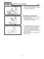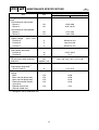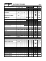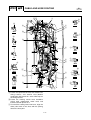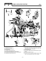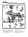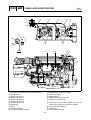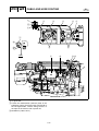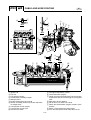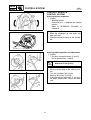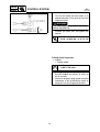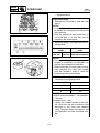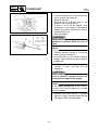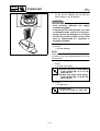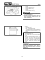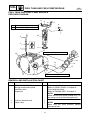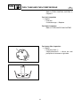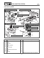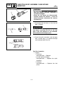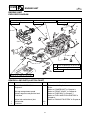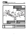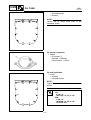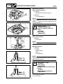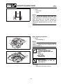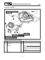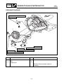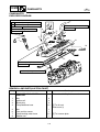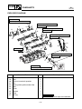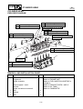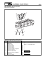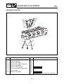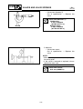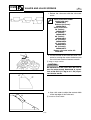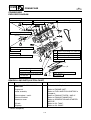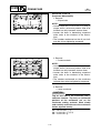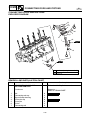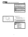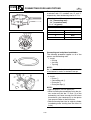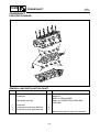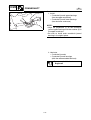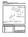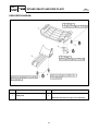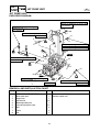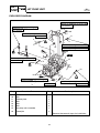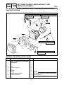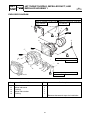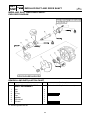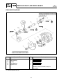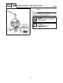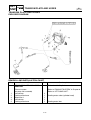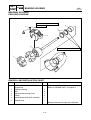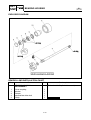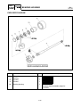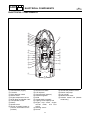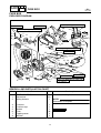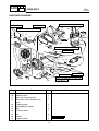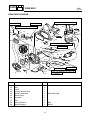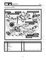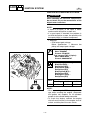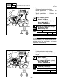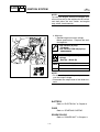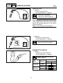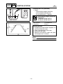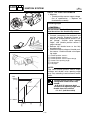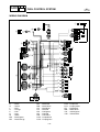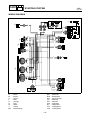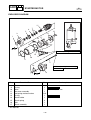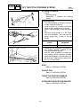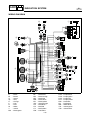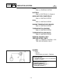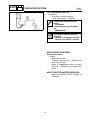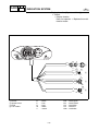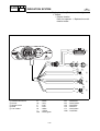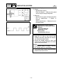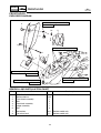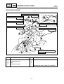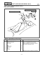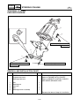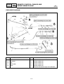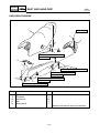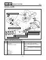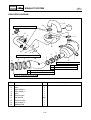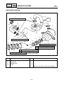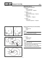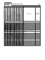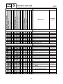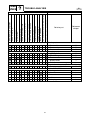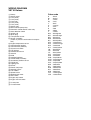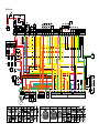
1
WaveRunner
VX110 Sport
VX110 Deluxe
SERVICE MANUAL
*LIT186160291*
LIT-18616-02-91
F1K-28197-1H-11
E
NOTICE
This manual has been prepared by Yamaha primarily for use by Yamaha dealers and their trained
mechanics when performing maintenance procedures and repairs to Yamaha equipment. It has
been written to suit the needs of persons who have a basic understanding of the mechanical and
electrical concepts and procedures inherent in the work, for without such knowledge attempted
repairs or service to the equipment could render it unsafe or unfit for use.
Because Yamaha has a policy of continuously improving its products, models may differ in detail
from the descriptions and illustrations given in this publication. Use only the latest edition of this
manual. Authorized Yamaha dealers are notified periodically of modifications and significant
changes in specifications and procedures, and these are incorporated in successive editions of this
manual.
A10001-0*
WaveRunner
VX110 Sport, VX110 Deluxe
SERVICE MANUAL
©2005 by Yamaha Motor Corporation, USA
1st Edition, January 2005
All rights reserved.
Any reprinting or unauthorized use
without the written permission of
Yamaha Motor Corporation, USA
is expressly prohibited.
Printed in USA
LIT-18616-02-91
E
HOW TO USE THIS MANUAL
MANUAL FORMAT
All of the procedures in this manual are organized in a sequential, step-by-step format. The information has been compiled to provide the mechanic with an easy to read, handy reference that contains
comprehensive explanations of all disassembly, repair, assembly, and inspection operations.
In this revised format, the condition of a faulty component will precede an arrow symbol and the
course of action required will follow the symbol, e.g.,
• Bearings
Pitting/scratches → Replace.
To assist you in finding your way through this manual, the section title and major heading is given at
the top of every page.
ILLUSTRATIONS
The illustrations within this service manual represent all of the designated models.
CROSS REFERENCES
The cross references have been kept to a minimum. Cross references will direct you to the appropriate section or chapter.
E
IMPORTANT INFORMATION
In this Service Manual particularly important information is distinguished in the following ways.
The Safety Alert Symbol means ATTENTION! BECOME ALERT! YOUR SAFETY IS
INVOLVED!
WARNING
Failure to follow WARNING instructions could result in severe injury or death to the machine
operator, passenger(s), a bystander, or a person inspecting or repairing the watercraft.
CAUTION:
A CAUTION indicates special precautions that must be taken to avoid damage to the watercraft.
NOTE:
A NOTE provides key information to make procedures easier or clearer.
IMPORTANT:
This part has been subjected to change of specification during production.
E
HOW TO USE THIS MANUAL
1 To help identify parts and clarify procedure steps, there are exploded diagrams at the start of
each removal and disassembly section.
2 Numbers are given in the order of the jobs in the exploded diagram.
3 Symbols indicate parts to be lubricated or replaced (see “SYMBOLS”).
4 A job instruction chart accompanies the exploded diagram, providing the order of jobs, names of
parts, notes in jobs, etc.
5 Dimension figures and the number of parts, are provided for fasteners that require a tightening
torque.
Example:
Bolt or screw size
10 × 25 mm
: M10 (D) × 25 mm (L)
D
L
6 Jobs requiring more information (such as special tools and technical data) are described
sequentially.
E
1
A50001-1-4
2
GEN
INFO
SYMBOLS
Symbols 1 to 9 are designed to indicate the
content of a chapter.
SPEC
3
1
2
3
4
5
6
7
8
9
4
INSP
ADJ
FUEL
5
6
JET
PUMP
POWR
7
General Information
Specifications
Periodic Inspection and Adjustment
Fuel System
Power Unit
Jet Pump Unit
Electrical System
Hull and Hood
Trouble Analysis
8
–
ELEC
9
+
HULL
HOOD
Symbols 0 to E indicate specific data.
0
0
A
B
C
D
E
TRBL
ANLS
A
B
C
D
Special service tool
Specified oil or fluid
Specified engine speed
Specified tightening torque
Specified measurement
Specified electrical value
(resistance, voltage, electric current)
T.
R.
E
Symbols F to I in an exploded diagram indicate the grade of lubricant and the lubrication
point.
F
E
G
H
A
I
1104J
1280B
J
M
K
GM
L
LT
LT
271
242
M
N
LT
572
SS
F Apply Yamaha 4-stroke motor oil
G Apply water resistant grease
(Yamaha grease A, Yamaha marine grease)
H Apply ThreeBond 1104J or ThreeBond 1280B
I Apply molybdenum disulfide grease
Symbols J to N in an exploded diagram indicate the type of sealant or locking agent and
the application point.
J
K
L
M
N
Apply Gasket Maker
Apply LOCTITE 271 (red)
Apply LOCTITE 242 (blue)
Apply LOCTITE 572
Apply silicone sealant
NOTE:
Additional symbols may be used in this manual.
E
A30000-0
INDEX
GENERAL INFORMATION
SPECIFICATIONS
PERIODIC INSPECTION AND
ADJUSTMENT
FUEL SYSTEM
POWER UNIT
JET PUMP UNIT
GEN
INFO
SPEC
INSP
ADJ
FUEL
POWR
JET
PUMP
–
ELECTRICAL SYSTEM
HULL AND HOOD
TROUBLE ANALYSIS
+
ELEC
HULL
HOOD
TRBL
ANLS
1
2
3
4
5
6
7
8
9
GEN
INFO
E
CHAPTER 1
GENERAL INFORMATION
IDENTIFICATION NUMBERS ......................................................................... 1-1
PRIMARY l.D. NUMBER ...........................................................................1-1
ENGINE SERIAL NUMBER ...................................................................... 1-1
JET PUMP UNIT SERIAL NUMBER .........................................................1-1
HULL IDENTIFICATION NUMBER (H.l.N.)............................................... 1-1
SAFETY WHILE WORKING...................................................................... 1-2
FIRE PREVENTION .................................................................................. 1-2
VENTILATION ........................................................................................... 1-2
SELF-PROTECTION................................................................................. 1-2
PARTS, LUBRICANTS, AND SEALANTS ................................................ 1-2
GOOD WORKING PRACTICES ............................................................... 1-3
DISASSEMBLY AND ASSEMBLY ............................................................ 1-4
SPECIAL SERVICE TOOLS ...........................................................................1-5
MEASURING............................................................................................. 1-5
REMOVAL AND INSTALLATION.............................................................. 1-7
1
2
3
4
5
6
7
8
9
GEN
INFO
IDENTIFICATION NUMBERS
E
A60700-0*
IDENTIFICATION NUMBERS
PRIMARY l.D. NUMBER
The primary l.D. number is stamped on a label
attached to the inside of the engine compartment.
Starting primary l.D. number:
F1K: 800101
ENGINE SERIAL NUMBER
The engine serial number is stamped on a
label attached to the engine unit.
Starting serial number:
6D3: 1000001
JET PUMP UNIT SERIAL NUMBER
The jet pump unit serial number is stamped on
a label attached to the intermediate housing.
HULL IDENTIFICATION NUMBER
(H.l.N.)
The H.l.N. is stamped on a plate attached to
the aft deck.
1-1
GEN
INFO
SAFETY WHILE WORKING
E
SAFETY WHILE WORKING
To prevent and accident or injury and to
ensure quality service, follow the safety procedures provided below.
FIRE PREVENTION
Gasoline is highly flammable.
Keep gasoline and all flammable products
away from heat, sparks, and open flames.
VENTILATION
Gasoline vapor and exhaust gas are heavier
than air and extremely poisonous. If inhaled in
large quantities they may cause loss of consciousness and death within a short time.
When test running an engine indoors (e.g., in a
water tank), be sure to do so where adequate
ventilation can be maintained.
SELF-PROTECTION
Protect your eyes by wearing safety glasses or
safety goggles during all operation involving
drilling and grinding, or when using an air compressor.
Protect your hands and feet by wearing protective gloves or safety shoes when necessary.
PARTS, LUBRICANTS, AND
SEALANTS
Use only genuine Yamaha parts, lubricants,
and sealants or those recommended by
Yamaha, when servicing or repairing the
watercraft.
1-2
GEN
INFO
SAFETY WHILE WORKING
E
Under normal conditions, the lubricants mentioned in this manual should not harm or be
hazardous to your skin. However, you should
follow these precautions to minimize any risk
when working with lubricants.
1. Maintain good standards of personal and
industrial hygiene.
2. Change and wash clothing as soon as
possible if soiled with lubricants.
3. Avoid contact with skin. Do not, for example, place a soiled rag in your pocket.
4. Wash hands and any other part of the
body thoroughly with soap and hot water
after contact with a lubricant or lubricant
soiled clothing has been made.
5. To protect your skin, apply a protective
cream to your hands before working on the
watercraft.
6. Keep a supply of clean, lint-free cloths for
wiping up spills, etc.
GOOD WORKING PRACTICES
1. The right tools
Use the recommended special service
tools to protect parts from damage. Use
the right tool in the right manner—do not
improvise.
2. Tightening torques
Follow the tightening torque specifications
provided throughout the manual. When
tightening nuts, bolts, and screws, tighten
the large sizes first, and tighten fasteners
starting in the center and moving outward.
1-3
GEN
INFO
SAFETY WHILE WORKING
E
3. Non-reusable parts
Always use new gaskets, seals, O-rings,
oil seals, cotter pins, circlips, etc., when
installing or assembling parts.
DISASSEMBLY AND ASSEMBLY
1. Use compressed air to remove dust and
dirt during disassembly.
2. Apply engine oil to the contact surfaces of
moving parts during assembly.
3. Install bearings with the manufacture identification mark in the direction indication in
the installation procedure. In addition, be
sure to lubricate the bearings liberally.
4. Apply a thin coat of water-resistant grease
to the lip and periphery of an oil seal
before installation.
5. Check that moving parts operate normally
after assembly.
1-4
GEN
INFO
SPECIAL SERVICE TOOLS
E
SPECIAL SERVICE TOOLS
Using the correct special service tools recommended by Yamaha, will aid the work and
enable accurate assembly and tune-up. Improvisations and using improper tools can damage the equipment.
1 90890-06583
2
NOTE:
• For U.S.A. and Canada, use part numbers
starting with “J-”, “YB-”, “YM-”, “YS-”, “YU-” or
“YW-”.
• For other countries, use part numbers starting with “90890-”.
90890-06584
MEASURING
3
1 Dial gauge stand
P/N. 90890-06583
2 Dial gauge needle
P/N. 90890-06584
3 Dial gauge stand set
P/N. YB-06585
90890-06585
4 Dial indicator gauge
P/N. YU-03097
Dial gauge set
P/N. 90890-01252
5 Pocket tester
P/N. YU-03112
90890-03112
6 Digital multimeter
P/N. YU-34899-A
7 Digital circuit tester
P/N. 90890-03174
8 Fuel pressure gauge adapter
P/N. YW-06842
90890-06842
9 Fuel pressure gauge
P/N. YB-06766
90890-06786
YB-06585
90890-06585
4 YU-03097
90890-01252
5 YU-03112
6
7 90890-03174
8 YW-06842
90890-03112
9 YB-06766
YU-34899-A
90890-06842
90890-06786
1-5
GEN
INFO
0 90890-06582
B YU-33223-1
SPECIAL SERVICE TOOLS
A YU-03017
90890-06759
90890-03160
C YU-39991
D 90890-03172
E YM-34487
F YB-06867 (-06767)
G YB-06870 (-06770)
H YB-06848
I YB-06877 (-06777)
J YB-35956-A
90890-06754
90890-06870 (-06770)
90890-06877 (-06777)
0 Compression gauge extension
P/N. 90890-06582
A Cylinder gauge set
P/N. YU-03017
90890-06759
B Compression gauge
P/N. YU-33223-1
90890-03160
C Peak voltage adapter
P/N. YU-39991
D Peak voltage adapter B
P/N. 90890-03172
E Spark checker
P/N. YM-34487
Ignition tester
P/N. 90890-06754
F Test harness (2 pins)
P/N. New: YB-06867
Current: YB-06767
Test harness FWY-2 (2 pins)
P/N. New: 90890-06867
Current: 90890-06767
G Test harness (3 pins)
P/N. New: YB-06870
Current: YB-06770
Test harness SMT250-3 (3 pins)
P/N. New: 90890-06870
Current: 90890-06770
H Test harness (6 pins)
P/N. YB-06848
Test harness FSW-6A (6 pins)
P/N. 90890-06848
I Test harness (3 pins)
P/N. New: YB-06877
Current: YB-06777
Test harness HM090-3 (3 pins)
P/N. New: 90890-06877
Current: 90890-06777
J Lower unit pressure/vacuum tester
P/N. YB-35956-A
Vacuum/pressure pump gauge set
P/N. 90890-06756
90890-06867 (-06767)
90890-06848
90890-06756
1-6
E
GEN
INFO
SPECIAL SERVICE TOOLS
E
K Yamaha diagnostic system
P/N. 60V-85300-02-00
L Yamaha diagnostic system
P/N. 60V-WS853-03
K 60V-85300-02-00
L 60V-WS853-03
REMOVAL AND INSTALLATION
1 YB-01426
90890-01426
1 Oil filter wrench
P/N. YB-01426
90890-01426
2 Coupler wrench
P/N. YW-06551
90890-06551
3 Sheave holder
P/N. YS-01880-A
90890-01701
4 Rotor puller
P/N. YM-01082
90890-01080
5 Universal magneto and rotor holder
P/N. YU-01235
Rotor holder
P/N. 90890-01235
6 Bearing housing needle bearing installer
(reduction drive gear)
P/N. YB-06111
2 YW-06551
90890-06551
3 YS-01880-A
4 YM-01082
5 YU-01235
6 YB-06111
90890-01701
90890-01235
90890-01080
1-7
GEN
INFO
SPECIAL SERVICE TOOLS
7 YB-06276-B
8 90890-06657
9 YM-01253
0 YM-04114 (ø19 mm)
90890-04019
A YM-04111 (ø4.0 mm)
90890-04111 (ø4.0 mm)
YM-04116 (ø4.5 mm)
90890-04116 (ø4.5 mm)
7 Forward gear bearing cup installer
(reduction drive gear)
P/N. YB-06276-B
8 Ball bearing attachment
(reduction drive gear)
P/N. 90890-06657
9 Valve spring compressor
P/N. YM-01253
90890-04019
0 Valve spring compressor attachment
P/N. YM-04114 (ø19 mm)
90890-04114 (ø19 mm)
YM-04108 (ø22 mm)
90890-04108 (ø22 mm)
A Valve guide remover
P/N. YM-04111 (ø4.0 mm)
90890-04111 (ø4.0 mm)
YM-04116 (ø4.5 mm)
90890-04116 (ø4.5 mm)
B Valve guide installer
P/N. YM-04112 (ø4.0 mm)
90890-04112 (ø4.0 mm)
YM-04117 (ø4.5 mm)
90890-04117 (ø4.5 mm)
C Valve guide reamer
P/N. YM-04113 (ø4.0 mm)
90890-04113 (ø4.0 mm)
YM-04118 (ø4.5 mm)
90890-04118 (ø4.5 mm)
D Valve seat cutter
Intake
P/N. 90890-06813 (60°)
90890-06814 (45°)
90890-06815 (30°)
Exhaust
P/N. 90890-06315 (60°)
90890-06312 (45°)
90890-06328 (30°)
90890-04114 (ø19 mm)
YM-04108 (ø22 mm)
90890-04108 (ø22 mm)
B YM-04112 (ø4.0 mm)
90890-04112 (ø4.0 mm)
YM-04117 (ø4.5 mm)
90890-04117 (ø4.5 mm)
C YM-04113 (ø4.0 mm)
90890-04113 (ø4.0 mm)
YM-04118 (ø4.5 mm)
90890-04118 (ø4.5 mm)
D 90890-06813 (60°)
90890-06814 (45°)
90890-06815 (30°)
90890-06315 (60°)
90890-06312 (45°)
90890-06328 (30°)
1-8
E
GEN
INFO
SPECIAL SERVICE TOOLS
E Valve seat cutter holder
P/N. 90890-06811 (ø4.0 mm)
90890-06812 (ø4.5 mm)
F Neway valve seat cutter kit
P/N. YM-91044
G Piston ring compressor
P/N. YM-08037
90890-05158
H Drive shaft holder (impeller)
P/N. YB-06151
Drive shaft holder 5 (impeller)
P/N. 90890-06519
I Slide hammer and adapters
(jet pump bearing and reduction drive
gear)
P/N. YB-06096
J Stopper guide plate (jet pump bearing)
P/N. 90890-06501
K Bearing puller assembly
(jet pump bearing and reduction drive
gear)
P/N. 90890-06535
L Stopper guide stand
(jet pump bearing and reduction drive
gear)
P/N. 90890-06538
M Driver rod L3
(jet pump bearing and reduction drive
gear)
P/N. 90890-06652
N Bearing housing needle bearing remover
(jet pump bearing)
P/N. YB-06112
O Needle bearing attachment
(jet pump bearing, oil seal, and reduction
drive gear)
P/N. 90890-06614, 90890-06653
Ball bearing attachment
(jet pump oil seal)
P/N. 90890-06634
E 90890-06811 (ø4.0 mm) F YM-91044
90890-06812 (ø4.5 mm)
G YM-08037
90890-05158
H YB-06151
I YB-06096
J 90890-06501
K 90890-06535
L 90890-06538
M 90890-06652
N YB-06112
O 90890-06614
90890-06519
E
90890-06653
90890-06634
1-9
GEN
INFO
SPECIAL SERVICE TOOLS
P YB-06085
Q 90890-06631
R YB-06071
S 90890-06606
T YB-06552
U YB-06156
90890-06552
E
P Outer race installer—forward gear
(jet pump oil seal and reduction drive gear)
P/N. YB-06085
Q Ball bearing attachment
(jet pump oil seal and reduction drive gear)
P/N. 90890-06631
R Driver handle—large
(intermediate shaft, jet pump, and
reduction drive gear)
P/N. YB-06071
S Driver rod LS
(intermediate shaft, jet pump, and
reduction drive gear)
P/N. 90890-06606
T Crankshaft holder (intermediate shaft)
P/N. YB-06552
Crankshaft holder 20 (intermediate shaft)
P/N. 90890-06552
U Bearing outer race attachment
(intermediate shaft and reduction drive
gear)
P/N. 90890-06624, 90890-06628
V Roller bearing installer/remover
(intermediate shaft bearing and oil seals)
P/N. YB-06432
90890-06624
90890-06626
V YB-06432
1-10
SPEC
E
CHAPTER 2
SPECIFICATIONS
GENERAL SPECIFICATIONS ....................................................................... 2-1
MAINTENANCE SPECIFICATIONS ............................................................... 2-3
ENGINE .................................................................................................... 2-3
JET PUMP UNIT ......................................................................................2-6
HULL AND HOOD .................................................................................... 2-6
ELECTRICAL ............................................................................................ 2-7
TIGHTENING TORQUES .............................................................................. 2-10
SPECIFIED TORQUES...........................................................................2-10
GENERAL TORQUE ............................................................................... 2-15
CABLE AND HOSE ROUTING ..................................................................... 2-16
1
2
3
4
5
6
7
8
9
SPEC
GENERAL SPECIFICATIONS
E
GENERAL SPECIFICATIONS
Item
Model code
Hull
Engine/jet
Dimensions
Length
Width
Height
Dry weight
Maximum capacity
Performance
Maximum output
Maximum fuel consumption
Cruising range
Engine
Engine type
Displacement
Bore × stroke
Compression ratio
Exhaust system
Lubrication system
Cooling system
Starting system
Ignition system
Ignition timing
Spark plug model
(manufacturer)
Spark plug gap
Battery capacity
Generator output
Drive unit
Propulsion system
Jet pump type
Impeller rotation
Transmission
Jet thrust nozzle horizontal
angle
Jet thrust nozzle trim angle
Reverse system
Model
Unit
VX110 Sport
VX110 Deluxe
F1K
6D3
mm (in)
mm (in)
mm (in)
kg (lb)
Person/kg (lb)
3,220 (126.8)
1,170 (46.1)
1,150 (45.3)
325 (716)
3/240 (530)
kW (PS) @ r/min
l/h (US gal/h,
lmp gal/h)
h
81.0 (110) @ 8,000
28.0 (7.4, 6.2)
3
cm (cu. in)
mm (in)
Degree
2.1
4-stroke, L4, DOHC
1,052 (64.2)
76.0 × 58.0 (2.99 × 2.28)
11.4:1
Wet exhaust
Dry sump
Water cooled
Electric starter
TCI
BTDC 5–BTDC 35
CR9EB (NGK)
mm (in)
V/Ah
A @ r/min
0.7–0.8 (0.028–0.031)
12/19
12–21 @ 6,000
Degree
Jet pump
Axial flow, single stage
Counterclockwise (viewed from rear)
Constant mesh 1-speed
24 + 24
Degree
3
—
2-1
Reverse gate
SPEC
GENERAL SPECIFICATIONS
Item
Fuel and oil
Fuel type
Minimum fuel rating
Fuel tank capacity
Engine oil type
Engine oil grade
Engine oil quantity
(without oil filter replacement)
(with oil filter replacement)
E
Model
Unit
VX110 Sport
PON*
RON*
L
(US gal, Imp gal)
API
SAE
L
(US qt, Imp qt)
L
(US qt, Imp qt)
L
(US qt, Imp qt)
VX110 Deluxe
Regular unleaded gasoline
86
90
60 (15.9, 13.2)
4-stroke motor oil
SE, SF, SG, SH, SJ, SL
10W-30, 20W-40, 20W-50
4.3 (4.5, 3.8)
2.0 (2.1, 1.8)
2.2 (2.3, 1.9)
PON*: Pump Octane Number = (Motor Octane Number + Research Octane Number)/2
RON*: Research Octane Number
2-2
SPEC
MAINTENANCE SPECIFICATIONS
E
MAINTENANCE SPECIFICATIONS
ENGINE
Item
Cylinder head
Warpage limit
Compression pressure*1
Cylinder
Bore size
Taper limit
Out-of-round limit
Wear limit
Camshaft
Drive system
Intake A
Exhaust A
Intake and exhaust B
Camshaft cap inside diameter
Camshaft journal diameter
Intake
Exhaust
Camshaft-journal-to-camshaftcap clearance
Maximum camshaft runout
Timing chain
Model/number of links
Tensioning system
Valves, valve seats, valve guides
Valve clearance (cold)
Intake
Exhaust
Valve dimensions
Valve head diameter A
Intake
Exhaust
Model
Unit
VX110 Sport
VX110 Deluxe
mm (in)
0.1 (0.004)
kPa
(kgf/cm2, psi)
1,150 (11.5, 164)
mm (in)
mm (in)
mm (in)
mm (in)
76.000–76.015 (2.9921–2.9927)
0.08 (0.003)
0.05 (0.002)
76.100 (2.9961)
mm (in)
mm (in)
mm (in)
mm (in)
Chain drive
31.15 (1.226)
30.75 (1.211)
25.00 (0.984)
24.5 (0.9646)
mm (in)
mm (in)
mm (in)
24.46–24.47 (0.9630–0.9634)
24.44–24.45 (0.9622–0.9626)
0.05–0.06 (0.0020–0.0024)
mm (in)
0.03 (0.0012)
92RH2015-130/130
Automatic
mm (in)
mm (in)
0.11–0.20 (0.0043–0.0079)
0.25–0.34 (0.0098–0.0134)
mm (in)
mm (in)
22.9–23.1 (0.9016–0.9094)
24.4–24.6 (0.9606–0.9685)
*1 Measuring conditions:
Ambient temperature 20 °C (68 °F), wide open throttle, with spark plugs removed from all
cylinders.
The figures are for reference only.
2-3
SPEC
MAINTENANCE SPECIFICATIONS
Item
Valve face width B
Intake
Exhaust
Valve seat width C
Intake
Exhaust
Valve margin thickness D
Intake
Exhaust
Valve stem diameter
Intake
Exhaust
Valve guide inside diameter
Intake
Exhaust
Valve-stem-to-valve-guide
clearance
Intake
Exhaust
Valve stem runout
E
Model
Unit
VX110 Sport
VX110 Deluxe
mm (in)
mm (in)
1.91–2.64 (0.0752–0.1039)
1.91–2.64 (0.0752–0.1039)
mm (in)
mm (in)
0.90–1.10 (0.0354–0.0433)
0.90–1.10 (0.0354–0.0433)
mm (in)
mm (in)
0.85–1.15 (0.0335–0.0453)
0.85–1.15 (0.0335–0.0453)
mm (in)
mm (in)
3.975–3.990 (0.1565–0.1571)
4.465–4.480 (0.1758–0.1764)
mm (in)
mm (in)
4.000–4.012 (0.1575–0.1580)
4.500–4.512 (0.1772–0.1776)
mm (in)
mm (in)
mm (in)
0.010–0.037 (0.0004–0.0015)
0.020–0.047 (0.0008–0.0019)
0.01 (0.0004)
Valve spring
Free length
Intake
mm (in)
Exhaust
mm (in)
Installed length
Intake
mm (in)
Exhaust
mm (in)
Tilt limit
Intake
Degree/mm (in)
Exhaust
Degree/mm (in)
Piston
Piston-to-cylinder clearance
mm (in)
Piston diameter
mm (in)
Measuring point H*
mm (in)
Wear limit
mm (in)
Piston pin boss inside diameter
mm (in)
2-4
38.90 (1.53)
40.67 (1.60)
34.50 (1.36)
35.00 (1.38)
2.5/1.7 (0.067)
2.5/1.8 (0.071)
0.10–0.11 (0.0039–0.0043)
75.895–75.910 (2.9880–2.9886)
5 (0.2)
0.170 (0.0067)
17.002–17.013 (0.6694–0.6698)
SPEC
MAINTENANCE SPECIFICATIONS
Item
B
B
Model
Unit
Piston pins
Outside diameter
Wear limit
Piston ring
Top ring
T
Type
Dimension (B × T)
End gap (installed)
Ring groove clearance
2nd ring
Type
T
Dimensions (B × T)
End gap (installed)
Ring groove clearance
Oil ring
Dimensions
T
(B × T)
End gap (installed)
Ring groove clearance
Connecting rod
Big end oil clearance
Bearing color code
Small end inside diameter
Crankshaft
E
VX110 Sport
VX110 Deluxe
mm (in)
mm (in)
16.991–17.000 (0.6689–0.6693)
16.986 (0.6687)
mm (in)
mm (in)
mm (in)
Barrel
0.90 × 2.75 (0.04 × 0.11)
0.32–0.44 (0.0126–0.0173)
0.030–0.065 (0.0012–0.0026)
mm (in)
mm (in)
mm (in)
Taper
0.80 × 2.80 (0.03 × 0.11)
0.43–0.58 (0.0169–0.0228)
0.020–0.055 (0.0008–0.0022)
mm (in)
1.50 × 2.60 (0.06 × 0.10)
mm (in)
mm (in)
0.10–0.35 (0.0039–0.0138)
0.040–0.160 (0.0016–0.0063)
mm (in)
0.016–0.040 (0.0006–0.0016)
1. Brown 2. Black 3. Blue 4. Green
17.005–17.018 (0.6695–0.6700)
B
B
B
mm (in)
B
A
Crank width A
Deflection limit B
Crankshaft journal oil clearance
Bearing color code
Throttle body
Type/quantity
Manufacturer
ID mark
Trolling speed
mm (in)
mm (in)
mm (in)
304.8–306.0 (12.00–12.05)
0.03 (0.0012)
0.004–0.028 (0.0002–0.0011)
3. Red/Red 4. Red/Brown 5. Red/Black
6. Red/Blue 7. Red/Green
IM-230/1
Mikuni
6D300
1,550–1,750
r/min
2-5
SPEC
MAINTENANCE SPECIFICATIONS
Item
Fuel pump
Pump type
Fuel pressure
Oil filter
Oil filter type
Oil pump
Oil pump type
Rotor tip clearance
(scavenge pump)
Oil pump housing clearance
Rotor (feed pump)
Rotor (scavenge pump)
E
Model
Unit
VX110 Sport
kPa
(kgf/cm2, psi)
VX110 Deluxe
Electrical
320–327 (3.2–3.3, 46–47)
Cartridge type
mm (in)
Trochoid
0.09–0.15 (0.0035–0.0059)
mm (in)
mm (in)
0.09–0.17 (0.0035–0.0067)
0.09–0.15 (0.0035–0.0059)
JET PUMP UNIT
Item
Jet pump
Impeller material
Number of impeller blades
Impeller pitch angle
Impeller clearance
Impeller clearance limit
Drive shaft runout limit
Model
Unit
VX110 Sport
VX110 Deluxe
Stainless steel
3
21.2
0.35–0.45 (0.0138–0.0177)
0.6 (0.0236)
0.3 (0.0118)
Degree
mm (in)
mm (in)
mm (in)
HULL AND HOOD
Item
Free play
Throttle lever free play
Model
Unit
VX110 Sport
mm (in)
VX110 Deluxe
4–7 (0.16–0.28)
2-6
SPEC
MAINTENANCE SPECIFICATIONS
E
ELECTRICAL
Item
Battery
Type
Capacity
Specific gravity
ECM unit
(B/R – R/Y, B/W – R/Y,
B/Y – R/Y, B/G – R/Y)
Output peak voltage lower limit
@cranking (loaded)
@2,000 r/min (loaded)
@3,500 r/min (loaded)
Stator
Pickup coil
(W/B – B/O)
Output peak voltage
@cranking (unloaded)
@cranking (loaded)
@2,000 r/min (loaded)
@3,500 r/min (loaded)
Lighting coil
(G – G)
Output peak voltage
@cranking (unloaded)
@2,000 r/min (unloaded)
@3,500 r/min (unloaded)
Pickup coil resistance
(W/B – B/O)
Lighting coil resistance (G – G)
Minimum charging current
Ignition coil
Primary coil resistance
@20 °C (68 °F)
Secondary coil resistance
@20 °C (68 °F)
Rectifier/regulator
(R – B)
Output peak voltage
@3,500 r/min (unloaded)
Model
Unit
VX110 Sport
VX110 Deluxe
V/Ah
Fluid
12/19
1.28
V
V
V
90
130
140
V
V
V
V
8.0
6.9
19.4
25.1
V
V
V
Ω (color)
7.8
24.5
41.6
459–561
Ω (color)
A @ r/min
0.23–0.29
14 @ 6,000
Ω
1.19–1.61
kΩ
8.5–11.5
V
13.0
2-7
SPEC
MAINTENANCE SPECIFICATIONS
Item
Starter motor
Type
Output
Rating
Brush length
Wear limit
Commutator undercut
Limit
Commutator diameter
Limit
Starter relay
Rating
Thermoswitch
ON temperature (engine)
OFF temperature (engine)
ON temperature (exhaust)
OFF temperature (exhaust)
Engine temperature sensor
Engine temperature sensor
resistance
(B/Y – B/Y)
@ 20 °C (68 °F)
@ 100 °C (212 °F)
Speed sensor
Output voltage (on pulse)
Output pulse/one full turn
Throttle position sensor
Output voltage
@ throttle valve fully closed
Sensor 1
@ throttle valve fully opened
Sensor 2
Accelerator position sensor
Output voltage
@ throttle lever fully closed
Sensor 1
Sensor 2
@ throttle lever fully opened
Sensor 1
Sensor 2
E
Model
Unit
VX110 Sport
VX110 Deluxe
kW
Seconds
mm (in)
mm (in)
mm (in)
mm (in)
mm (in)
mm (in)
Constant mesh
0.8
30
12.5 (0.49)
6.5 (0.26)
0.7 (0.03)
0.2 (0.01)
28.0 (1.10)
27.0 (1.06)
Seconds
30
°C (°F)
°C (°F)
°C (°F)
°C (°F)
84–90 (183–194)
70–84 (158–183)
80–86 (176–187)
66–80 (151–176)
kΩ
kΩ
54.2–69.0
3.12–3.48
V
11.6
2
V
0.45–0.95
V
4.60–4.70
V
V
0.50–0.90
0.35–1.05
V
V
3.75–4.35
3.50–4.50
2-8
SPEC
MAINTENANCE SPECIFICATIONS
Item
Accelerator position sensor resistance*1
@ throttle lever fully closed
Sensor 1
Sensor 2
@ throttle lever fully opened
Sensor 1
Sensor 2
Cam position sensor
Output voltage
(G/O – B/O)
Position A
Position B
Position C
Fuel sender
Fuel sender resistance
Position A
Position B
Oil pressure switch
Oil pressure switch continuity
pressure
Fuel injector
Fuel injector resistance*1
@ 20 °C (68 °F)
Fuse
Rating
Main
Main and fuel pump relay
Main and fuel pump relay
Electronic control throttle
valve relay
Remote control unit
(Deluxe model only)
E
Model
Unit
VX110 Sport
VX110 Deluxe
kΩ
kΩ
0.50–0.90
0.35–10.50
kΩ
kΩ
3.75–4.35
3.60–4.50
V
V
V
More than 4.8
Less than 0.8
More than 4.8
Ω
Ω
133.5–136.5
5–7
kPa
(kgf/cm2, psi)
128 (1.28, 18.2)–167 (1.67, 23.8)
Ω
11.5–12.5
V/A
V/A
V/A
V/A
12/30
12/20
12/10
12/10
V/A
12/3
*1: The figures are for reference only.
2-9
SPEC
TIGHTENING TORQUES
E
TIGHTENING TORQUES
SPECIFIED TORQUES
M8
—
M6
M6
4
1
1
2
—
—
2
—
—
2
Bolt
M10
4
Bolt
M6
3
Bolt
M8
4
Bolt
M8
11
17
17
7.8
7.6
3.4
3.4
3.4
3.4
2.0
15
39
3.7
7.6
22
22
35
22
22
35
1.7
1.7
0.78
0.76
0.34
0.34
0.34
0.34
0.2
1.5
3.9
0.37
0.76
2.2
2.2
3.5
2.2
2.2
3.5
12
12
5.6
5.5
2.5
2.5
2.5
2.5
1.4
11
28
2.7
5.5
16
16
25
16
16
25
*1: For details, refer to the tightening procedures in this manual.
2-10
LT
Bolt
—
Bolt
Bolt
572
2
2
LT
M8
M5
242
Bolt
Screw
LT
2
271
M8
4-7
4-10
4-10
LT
Bolt
4-7
271
2
E
M6
LT
Bolt
4-7
4-7
4-7
4-7
4-7
4-7
4-10
572
M8
—
—
—
—
M8
LT
Bolt
Nut
—
Nut
Nut
Bolt
4-1
4-1
572
M5
4-1
5-1
3-17
5-1
5-8
5-8
5-8
LT
Screw
1
2
2
4
4
4
1
1
2
4
2.3
4.6
4.3
2.7
0.9
1.1
12
11
1.8
4.7
12
9.4
6.4
13
11
28
9.4
2.5
242
1st
2nd
1st
Inner exhaust joint clamp
2nd
1st
*1
2nd
Exhaust pipe 2
3rd
1st
Exhaust pipe end
2nd
1st
Exhaust pipe 1
2nd
3rd
1st
Exhaust manifold
2nd
3rd
—
—
0.32
0.64
0.59
0.37
0.12
0.15
1.7
1.5
0.25
0.65
1.7
1.3
0.88
1.8
1.5
3.9
1.3
0.35
LT
Intake manifold bracket/
wiring harness bracket 1
Fuel rail
Sensor assembly
Engine
Engine unit
Oil filter
Coupling cover
Thermoswitch (exhaust)
Outer exhaust joint
clamp
1st
2nd
1st
2nd
Nut
—
3.2
6.4
5.9
3.7
1.2
1.5
17
15
2.5
6.5
17
13
8.8
18
15
39
13
3.5
Refer to
page
5-9
572
Intake manifold
9
LT
Air filter case
Air filter case bracket
Air intake hose clamp
Throttle cable
Accelerator position sensor
Throttle body assembly
—
Remarks
5-10
242
Air filter case cover
Nut
Tightening torque
N•m kgf•m ft•lb
LT
Fuel system
1st
Retainer/fuel pump
module
2nd
Fuel filler neck/rubber seal
Fuel filter hose clamp
Thread
Q’ty
size
5-10
242
Part
name
Part to tightened
5-11
TIGHTENING TORQUES
Drain plug (engine oil)
Strainer
1st
2nd
Drive coupling
Reduction drive gear
case
1st
2nd
1st
2nd
Starter motor lead
Starter motor
Generator cover
Flywheel magneto
Starter clutch
1st
2nd
M5
9
Bolt
M5
3
Bolt
M6
2
Bolt
M6
24
Screw
M4
M6
1
6
M8
4
Bolt
M8
1
Bolt
M6
2
—
—
1
Bolt
M6
2
Bolt
M8
5
Nut
Bolt
—
M8
1
2
Bolt
M10
8
Bolt
Bolt
M10
M8
1
6
Bolt
2-11
LT
Bolt
572
8
LT
M6
572
Bolt
LT
2
572
M6
LT
Bolt
572
2
LT
M10
5-12
572
Bolt
5-12
LT
2
5-15
572
1st
2nd
—
5-15
E
Oil pump assembly
Nut
5-12
5-15
E
Anode
1
5-15
E
Oil cooler cover
M6
LT
Oil strainer
Bolt
5-12
5-15
572
Baffle plate
5
5-15
E
Oil breather plate
M10
LT
Oil tank cover
Bolt
5-12
5-15
572
Bracket (coupling cover)
3
5-21
5-21
5-21
LT
Oil tank stay
M6
5-12
572
Oil tank
Bolt
LT
Plastic tie/collar
1st
2nd
1st
2nd
1st
2nd
3rd
1st
2nd
3rd
1st
2nd
1st
2nd
1st
2nd
1st
2nd
1st
2nd
1st
2nd
2
Refer to
page
5-24
572
Oil tank
M6
LT
Ground lead box
Bolt
Remarks
5-24
572
1st
2nd
Tightening torque
N•m kgf•m ft•lb
3.7 0.37 2.7
7.6 0.76 5.5
7.6 0.76 5.5
15
1.5
11
39
3.9
28
3.7 0.37 2.7
7.6 0.76 5.5
2.0
0.2
1.4
15
1.5
11
39
3.9
28
2.0
0.2
1.4
15
1.5
11
39
3.9
28
3.7 0.37 2.7
7.6 0.76 5.5
3.7 0.37 2.7
7.6 0.76 5.5
1.9 0.19 1.4
4.4 0.44 3.2
1.9 0.19 1.4
4.4 0.44 3.2
3.7 0.37 2.7
7.6 0.76 5.5
3.7 0.37 2.7
7.6 0.76 5.5
3.8 0.38 2.7
10
1.0
7.2
15
1.5
11
28
2.8
20
13
1.3
9.4
3.7 0.37 2.7
7.6 0.76 5.5
28
2.8
20
3.7 0.37 2.7
7.6 0.76 5.5
15
1.5
11
28
2.8
20
4.9 0.49 3.5
18
1.8
13
15
1.5
11
50
5.0
36
75
7.5
54
24
2.4
17
5-24
5-33
5-33
A
LT
Oil separator
Thread
Q’ty
size
572
Part
name
Part to tightened
E
E
SPEC
5-33
5-33
5-33
TIGHTENING TORQUES
Nut
—
5
—
Bolt
—
1
2
1
Anode cover
Bolt
Oil pan
Bolt
Bolt
—
M6
—
M6
M8
M6
M6
15
10
Bolt
M9
10
Bolt
—
M6
—
1
1
Nut
—
8
Lower crankcase
Oil pipe
Oil filter bolt
Connecting rod cap
1st
2nd
1
*1: For details, refer to the tightening procedures in this manual.
2-12
LT
242
LT
242
242
LT
LT
242
LT
572
LT
572
5-54
5-54
5-71
5-71
5-71
E
3
E
—
E
Nut
5-54
E
2
E
—
E
Nut
5-41
5-43
5-43
5-43
5-43
5-43
5-43
5-54
E
6
1
2
10
18
2
2
3
E
M6
M6
M6
M6
M6
M7
M7
M6
E
Bolt
Bolt
Bolt
Bolt
Bolt
Bolt
Bolt
Bolt
5-41
LT
1
5-36
5-36
5-36
5-41
5-41
5-41
572
M6
0.49 3.5
1.4
10
1.4
10
1.3
9.4
0.76 5.5
1.0
7.2
0.37 2.7
0.76 5.5
1.2
8.7
1.0
7.2
1.0
7.2
1.0
7.2
1.0
7.2
2.4
17
2.4
17
1.0
7.2
2.0
14
140 ± 5°
20
2.0
14
121 ± 5°
20
2.0
14
105 ± 5°
15
1.5
11
7.6 0.76 5.5
8.4 0.84 6.1
12
1.2
8.7
20
2.0
14
12
1.2
8.7
12
1.2
8.7
7.8 0.78 5.6
Loosen completely
15
1.5
11
±
49 5°
12
1.2
8.7
35
3.5
25
20
2.0
14
120 ± 5°
LT
Bolt
4.9
14
14
13
7.6
10
3.7
7.6
12
10
10
10
10
24
24
10
20
572
2
2
3
4
4
1
5-36
LT
M5
M6
M6
—
M6
M6
3.5
Refer to
page
271
Bolt
Bolt
Bolt
—
Bolt
Bolt
0.49
LT
4.9
572
1
LT
M5
Remarks
572
Bolt
1st
2nd
Cylinder head*1
1st
2nd
1st
2nd
Engine temperature sensor
Thermoswitch (engine)
Oil pressure switch
1st
2nd
3rd
4th
Tightening torque
N•m kgf•m ft•lb
M
5-71
5-71
5-71
E
Washer/pickup coil lead and
lighting coil lead
Pickup coil
Holder (wiring harness)
Lighting coil
Spark plug
Ignition coil
Cam position sensor
1st
Cooling water pipe
2nd
Cylinder head cover
Timing chain tensioner cap bolt
Timing chain tensioner
Exhaust camshaft cap
Intake camshaft cap
Exhaust camshaft sprocket
Intake camshaft sprocket
Thread
Q’ty
size
5-71
E
Part
name
Part to tightened
E
5-74
5-74
E
SPEC
5-80
SPEC
TIGHTENING TORQUES
Part to tightened
Part
name
Jet pump unit
Steering cable joint
Ride plate
Nut
Bolt
Intake grate
Bolt
Thread
Q’ty
size
Tightening torque
N•m kgf•m ft•lb
Reverse gate
Reverse gate ball joint
Reverse gate spring
Bolt
Nut
Nut
M8
—
—
—
—
Bolt
Bolt
M8
M10
2
1
1
1
1
2
4
17
14
15
7.8
7.8
1.2
2.2
15
40
Bolt
M6
4
6.6
0.66
4.8
Bolt
Impeller
Nut
Bolt
Driven
coupling
—
M6
M22
—
M8
3
1
4
4
7.8
75
26
17
0.78
7.5
2.6
1.7
5.6
54
19
12
M24
1
36
3.6
26
—
2
4.2
0.42
3.0
6-18
4
2
4
4
2
2
2
4
1
1
4
3
20
1.1
1.1
3.7
3.4
3.4
1.2
17
6.9
20
16
16
2.0
0.11
0.11
0.37
0.34
0.34
0.12
1.7
0.69
2.0
1.6
1.6
14
0.8
0.8
2.7
2.5
2.5
0.9
12
5.0
14
12
12
8-1
Screw
Screw
Screw
Bolt
Bolt
Ball joint
Bolt
Bolt
Bolt
M8
M4
M5
M6
M5
M5
M5
M8
—
M8
M8
M8
Bolt
M6
2
6.9
0.69
5.0
Nut
—
1
5.9
0.59
4.3
2-13
6-3
LT
LT
LT
6-1
LT
LT
572
LT
572
LT
6-8
6-8
6-15
6-18
6-19
LT
242
242
LT
LT
LT
LT
572
LT
572
6-6
271
LT
271
LT
572
6-5
6-5
6-5
6-5
6-3
6-6
6-6
271
6-3
572
271
6-3
8-23
LT
242
572
LT
LT
242
LT
8-1
8-4
8-4
8-4
8-20
8-20
8-20
8-21
8-21
271
LT
572
LT
572
8-1
LT
Lower handlebar cover
Throttle lever assembly
Handlebar switch assembly
Grip end
Steering column
Steering cable ball joint
Steering arm
Steering sensor
Spacer
Shift cable holder
(Deluxe model only)
Shift cable seal
(Deluxe model only)
Screw
12
10
11
5.6
5.6
0.9
1.6
11
29
6-1
242
Upper handlebar cover
Bolt
1.7
1.4
1.5
0.78
0.78
0.12
0.22
1.5
4.0
LT
2
242
M8
Clamp
Hull and hood
Handlebar holder
4.9
LT
Bolt
Driven coupling
0.68
572
Bracket
Jet thrust nozzle
Nozzle/bracket
Water inlet cover/water inlet
strainer
Cap
Impeller
Transom plate
Intermediate housing cover
6.8
242
Bolt
Nut
6-3
6-1
242
Rubber plate
Spout hose clamp
4.9
12
5.5
29
2.7
5.6
29
572
Bolt
4
1
4
4
2
0.68
1.7
0.76
4.0
0.37
0.78
4.0
Refer to
page
Jet pump unit assembly
Screw
2
6.8
17
7.6
40
3.7
7.8
40
Remarks
—
M8
M6
M10
M5
M6
M10
M6
—
Speed sensor
1
4
E
8-23
TIGHTENING TORQUES
Spout
Protector (bow)
Bow eye
Drain plug/packing
Engine mount
Engine damper
Tightening torque
N•m kgf•m ft•lb
Remarks
Refer to
page
1
3.8
0.38
2.7
Nut
—
1
6.5
0.65
4.7
8-23
Nut
—
1
6.8
0.68
4.9
8-23
Nut
Bolt
Nut
Bolt
Bolt
Bolt
Bolt
Nut
—
M6
—
M6
M5
M6
M6
—
1
1
1
2
2
4
2
4
5.9
6.9
5.9
6.9
1.9
6.9
6.9
15
0.59
0.69
0.59
0.69
0.19
0.69
0.69
1.5
4.3
5.0
4.3
5.0
1.4
5.0
5.0
11
Screw
M5
2
3.7
0.37
2.7
Bolt
M5
4
3.9
0.39
2.8
Bolt
M6
1
6.9
0.69
5.0
Bolt
Bolt
M6
M6
8
2
6.9
8.0
0.69
0.8
5.0
5.8
Nut
—
2
15
1.5
11
8-16
Nut
Nut
Nut
Bolt
Bolt
—
—
—
—
M6
1
4
2
1
2
4.2
6.9
15
26
6.4
0.42
0.69
1.5
2.6
0.64
3.0
5.0
11
19
4.6
8-17
8-28
8-28
8-28
8-28
Nut
—
6
5.4
0.54
3.9
8-31
—
—
—
—
—
—
2
1
2
—
2
Bolt
M8
2.7
2.7
2.7
1.7
1.7
12
Nut
—
15
1.5
11
8-36
Nut
Nut
Bolt
Screw
Bolt
Bolt
—
—
M6
M5
M8
M6
10
2
4
1
5
2
4
8
2
0.37
0.37
0.37
0.24
0.24
1.6
8-31
8-31
8-31
—
3.7
3.7
3.7
2.4
2.4
16
5.4
6.9
13
2.0
17
6.6
0.54
0.69
1.3
0.2
1.7
0.66
3.9
5.0
9.4
1.4
12
4.8
8-36
8-36
8-36
8-36
8-38
8-38
2-14
LT
LT
572
LT
LT
LT
242
572
8-11
8-11
8-16
LT
LT
LT
LT
572
572
8-11
271
8-11
572
8-23
8-23
8-23
8-8
8-8
8-8
8-8
8-8
LT
LT
8-23
572
242
572
572
LT
—
572
Nut
LT
572
8-31
LT
Cleat
Thread
Q’ty
size
572
Shift cable locknut
(Deluxe model only)
Steering cable locknut
(steering column side)
Steering cable locknut
(jet pump side)
Steering cable seal
Steering cable bracket
Speed sensor lead grommet
Hinge assembly
Hood lock assembly
Hinge assembly
Lid lock hook
Mirror (Deluxe model only)
Shift handle lever
(Deluxe model only)
Multifunction meter
Engine hatch cover
(Deluxe model only)
Engine hatch cover
Detent plate
Shift lever bracket
(Deluxe model only)
Pilot water outlet
Hand grip
Seat bracket
Seat lock projection
Seat lock assembly
Plate/rubber hose/exhaust
valve
Hose clamp 1
Hose clamp 2
Joint clamp 1 and 4
1st
Joint clamp 2 and 3
2nd
Sponson
Part
name
LT
Part to tightened
E
271
SPEC
8-36
SPEC
TIGHTENING TORQUES
Slant detection switch
Rectifier/regulator
Brush assembly/spacer
Starter motor rear cover
Remote control transmitter
cover
Nut A
Bolt B
8 mm
10 mm
12 mm
14 mm
17 mm
M5
M6
M8
M10
M12
M8
2
ø6
Tapping
screw
Bolt
Nut
Bolt
Tapping
screw
17
15
4.0
8.8
18
1.7
1.5
0.4
0.88
1.8
12
11
2.9
6.4
13
2
3.9
0.39
2.8
7-2
M8
—
M5
2
1
2
4.0
8.8
6.4
0.4
0.88
0.64
2.9
6.4
4.6
7-7
7-39
7-39
ø2
6
0.1
0.01
0.1
LT
Bolt
Refer to
page
572
2
4
4
LT
—
—
M6
Remarks
7-2
7-2
7-7
572
1st
2nd
Bracket
Nut
Nut
Bolt
Tightening torque
N•m kgf•m ft•lb
LT
Electrical
Fuse box
Fuse box bracket
ECM
Thread
Q’ty
size
7-7
572
Part
name
Part to tightened
E
7-64
GENERAL TORQUE
General torque
specifications
N•m kgf•m ft•lb
5.0
0.5
3.6
8.0
0.8
5.8
18
1.8
13
36
3.6
26
43
4.3
31
This chart specifies tightening torques for standard fasteners with a standard ISO thread
pitch. Tightening torque specifications for special components or assemblies are provided in
applicable sections of this manual. To avoid
warpage, tighten multi-fastener assemblies in
a crisscross fashion and progressive stages
until the specified tightening torque is reached.
Unless otherwise specified, tightening torque
specifications require clean, dry threads.
Components should be at room temperature.
2-15
SPEC
CABLE AND HOSE ROUTING
E
CABLE AND HOSE ROUTING
ÈÉ
1
G
A
F
K
E
B
J
K-K
D
K
A-A
2
3
A
B
K
J
1
J
B-B
C
B
J-J
B
4
A
C
I
C-C
C
I
I-I
D
D
A
5
6
5
6
D-D
I
I
2
I
E
E
F
F
0
Ê
H-H
7
H
H
H
B
G
7
6
2
E-E
8
G
7
6
A
G-G
F-F
0 9
1
2
3
4
5
6
7
8
9
0
A
B
C
D
E
F
G
H
I
J
K
Fuel tank breather hose
Steering cable
Throttle cable
Fuse box
Starter motor lead
Positive battery lead
Negative battery lead
Battery
Cooling water outlet hose
Shift cable (Deluxe model only)
Speed sensor lead
2-16
Cooling water inlet hose
Fuel hose
Electric fuel pump
Accelerator position sensor
Antenna lead (Deluxe model only)
Remote control unit lead (Deluxe model only)
Bilge hose joint
Cooling water hose joint
Cooling water pilot outlet hose
Accelerator position sensor lead
SPEC
CABLE AND HOSE ROUTING
ÈÉ
E
1
G
A
F
K
E
B
J
K-K
D
K
A-A
2
3
A
B
K
J
1
J
B-B
C
B
J-J
B
4
A
C
I
C-C
C
I
I-I
D
D
A
5
6
5
6
D-D
I
I
2
I
E
E
F
F
0
Ê
H-H
7
H
H
H
B
G
7
6
2
E-E
8
G
7
6
A
G-G
F-F
0 9
È Fasten the speed sensor lead, fuel sender lead,
wiring harness, and antenna lead (Deluxe
model only) with plastic tie 1 at the white tape on
the wiring harness.
É Fasten the steering sensor lead, handlebar
switch lead, multifunction meter lead, and
buzzer lead with plastic tie 2.
Ê To install the cooling water inlet hose, align the
white paint mark on the hose with the parting
line on the hose joint.
2-17
SPEC
CABLE AND HOSE ROUTING
12
Ï
J
A
3
4
C
Ð
J
M
B
4
890
567
C
D
E
A
H
F
H-H
B
C
D
H
I
Ó
G
HGF
E I
P
Ô
0
G-G
Ð
A
O
È
Ê
Q
I
Ò
É
L
Õ
A
G
5
F
E
È
Ë
E
É
N
Î
Í
D
1
2
3
4
5
6
7
8
9
0
A
K
P
G
Ñ
J
B
C
D
E
F
G
H
I
J
K
L
Multifunction meter
Handlebar switch lead
Buzzer
Shift cable (Deluxe model only)
Fuel hose
Relay assembly
Fuse box
ECM
Positive battery lead
Flushing hose
Cooling water outlet hose
2-18
B
Ì
Bilge hose
Battery breather hose
Battery
Negative battery lead
Starter motor lead
Speed sensor lead
Steering cable
Remote control unit lead (Deluxe model only)
Fuel tank breather hose
Antenna lead (Deluxe model only)
Ventilation hose
SPEC
CABLE AND HOSE ROUTING
12
Ï
J
A
3
4
C
Ð
J
M
B
4
890
567
C
D
E
A
H
F
H-H
B
C
D
H
I
Ó
G
HGF
E I
P
Ô
0
G-G
Ð
A
O
È
Ê
Q
I
Ò
É
L
Õ
A
G
5
F
E
È
Ë
E
É
N
Î
Í
D
M
N
O
P
Q
K
P
G
Ñ
J
B
Ì
É Fasten the speed sensor lead, fuel sender lead,
wiring harness, and antenna lead (Deluxe
model only) with plastic tie 1 at the white tape on
the wiring harness.
Ê Deluxe model
Ë Sport model
Ì To remote control unit (Deluxe model only)
Í Fasten the antenna lead and wiring harness
with a plastic tie at the white tape. (Deluxe
model only)
Î To engine unit (Deluxe model only)
Water separator
Electric fuel pump
Oil separator breather hose (to air intake duct)
Wiring harness
Cooling water inlet hose
È Fasten the steering sensor lead, handlebar
switch lead, multifunction meter lead, and
buzzer lead with plastic tie 2.
2-19
SPEC
CABLE AND HOSE ROUTING
12
Ï
J
A
3
4
C
Ð
J
M
B
4
890
567
C
D
E
A
H
F
H-H
B
C
D
H
I
Ó
G
HGF
E I
P
Ô
0
G-G
Ð
A
O
È
Ê
Q
I
Ò
É
L
Õ
A
G
5
F
E
K
P
G
Ñ
J
È
Ë
E
É
N
Î
Í
D
Ï To ventilation socket
Ð To fuel tank
Ñ Point the arrow on the cover toward the fuel
tank.
Ò Fasten the fuel hose with a plastic tie.
Ó To fuse box
Ô Fasten the wiring harness with a plastic tie at
the white tape.
Õ To ECM
2-20
B
Ì
SPEC
CABLE AND HOSE ROUTING
Ñ
E
2
Ò
2
Ê
8
2
Ó
A
Ê
B
C
5
6
Ì
4
Ê
ÎÏ
Í
2
7
F
É
8
Ë
3
F
C
2
E
E
D
A
B
Ô
1
È
2
2
Ð
2
2
Õ
2
2
F-F
1
2
3
4
5
6
7
8
E-E
D
È To install the cooling water outlet hose, align the
white paint mark on the cooling water hose with
the projection of the hose joint.
É To transom plate
Ê Fasten the cooling water outlet hose with a plastic tie.
Ë 25–45 mm (0.98–1.77 in)
Ì Fasten the oil separator breather (to oil tank)
hose and cooling water hose with a holder.
Cooling water inlet hose
Cooling water hose
Cooling water outlet hose
Flushing hose
Cylinder head breather hose
Oil separator breather hose (to oil tank)
Oil separator breather hose (to air intake duct)
Cooling water pilot outlet hose
2-21
SPEC
CABLE AND HOSE ROUTING
Ñ
E
2
Ò
2
Ê
8
2
Ó
A
Ê
B
C
5
6
Ì
4
Ê
ÎÏ
Í
2
7
F
É
8
Ë
3
F
C
2
E
E
D
A
B
Ô
1
È
2
2
Ð
2
2
Õ
2
2
F-F
E-E
D
Ñ Install the cooling water hose with the white
paint mark facing up.
Ò To cooling water pilot outlet
Ó Face the ends of the hose clamp towards the
bow.
Ô Install the hose onto the cooling water pipe until
the pipe reaches the curve in the hose.
Õ Insert the plastic tie completely into the hole in
the boss on the cylinder block.
Í Fasten the oil separator breather hose (to air
intake duct) and cooling water hose with a
holder.
Î Face the ends of the hose clamp towards the
starboard (right) side of the watercraft.
Ï Insert the cooling water hose to the paint mark.
Ð To install the cooling water hose, align the white
paint mark on the cooling water hose with the
arrow mark of the hose joint.
2-22
SPEC
CABLE AND HOSE ROUTING
1
3
E
4
5
6
7
È
2
É
Í
D
8
E
F
A-A
8
9
AB
0
A
A
C
Ê
Ë
Ì
1
2
3
4
5
6
7
8
9
0
A
Î
B
C
D
E
F
Oil separator breather hose (to air intake duct)
Wiring harness
Ignition coil lead #1
Ignition coil lead #2
Ignition coil lead #3
Ignition coil lead #4
Cam position sensor
Ignition coil
ECM
Rectifier/regulator
Oil pressure switch coupler
Thermoswitch (exhaust) coupler
Ground lead plate
Wiring harness
Thermoswitch (exhaust) lead
Oil pressure switch lead
È Fasten the oil separator breather hose (to air
intake duct) at the paint mark with a holder.
É 15–25 mm (0.59–0.98 in)
Ê To fuse box
Ë To multifunction meter
2-23
SPEC
CABLE AND HOSE ROUTING
1
3
E
4
5
6
7
È
2
É
Í
D
8
E
F
A-A
9
8
AB
0
A
Ê
Ë
Ì
Î
Ì To generator
Í Fasten the thermoswitch (exhaust) lead at the
protective sleeve, the oil pressure switch lead at
the corrugated tube, and the wiring harness at
the tape on the harness with a plastic tie.
Î 60–80 mm (2.36–3.15 in)
2-24
A
C
SPEC
CABLE AND HOSE ROUTING
Ð
Ú
0
E
2
5
D-D
Î
Ï
6
3
4
1
A-A
D
A
D
Ì
Í
Ì
Ù
Ë
Ê
Ë
A
É
È
9
8
5
5
C-C
B-B
Ñ
Ì
B
Ñ ÌÑ
C
Ò
Ô
Ó
Õ
7
B
C
Ö
×
Ø
1
2
3
4
5
6
7
È To engine temperature sensor
É To thermoswitch (engine)
Ê Route the engine thermoswitch lead and engine
temperature sensor lead through the corrugated
tube.
Ë More than 10 mm (0.39 in)
Ì Do not leave any slack in the lead.
Í Attach the thermoswitch (engine) coupler to the
bracket.
Î Attach a joint connector to the bracket.
Ï Pass the fuel injector leads under the fuel rail.
Ignition coil
Fuel rail
Fuel injector coupler
Throttle body assembly coupler
Wiring harness
Engine temperature sensor lead
Sensor assembly (intake air pressure and intake
air temperature)
8 Cam position sensor coupler
9 Cam position sensor lead
0 Oil pressure switch
2-25
SPEC
CABLE AND HOSE ROUTING
Ð
Ú
0
E
2
5
D-D
Î
Ï
6
3
4
1
A-A
D
A
D
Ì
Í
Ì
Ù
Ë
Ê
Ë
A
É
È
9
8
5
5
C-C
B-B
Ñ
Ì
B
Ñ ÌÑ
C
Ò
Ô
Ó
Õ
7
B
C
Ö
×
Ø
Õ Pass fuel injector lead #4 under the sensor
assembly (intake air pressure and intake air
temperature) lead.
Ö To oil pressure switch
× To thermoswitch (exhaust)
Ø To ground lead plate
Ù Bow end
Ú Make sure that the rubber boot is fitted properly
without any folds.
Ð Insert the plastic tie completely into the hole in
the engine hanger.
Ñ Fasten the wiring harness to a bracket on the
fuel rail with a plastic tie.
Ò Fasten the wiring harness and cam position
sensor within the range shown in the illustration
with a plastic tie.
Ó Split in wiring harness
Ô To cam position sensor
2-26
INSP
ADJ
E
CHAPTER 3
PERIODIC INSPECTION AND ADJUSTMENT
MAINTENANCE INTERVAL CHART .............................................................. 3-1
PERIODIC SERVICE .......................................................................................3-2
CONTROL SYSTEM ................................................................................. 3-2
Steering column inspection .................................................................3-2
Steering cable inspection and adjustment .......................................... 3-2
Throttle cable inspection and adjustment............................................3-4
Shift cable inspection and adjustment (Deluxe model only)................ 3-5
Trolling speed inspection .................................................................... 3-6
FUEL SYSTEM.......................................................................................... 3-7
Fuel line inspection .............................................................................3-7
Water separator inspection .................................................................3-8
POWER UNIT............................................................................................ 3-8
Valve clearance adjustment ................................................................3-8
Engine oil level check........................................................................3-14
Engine oil change — using oil changer............................................. 3-16
Air filter element clean....................................................................... 3-18
Spark plug inspection........................................................................3-20
ELECTRICAL .......................................................................................... 3-22
Battery inspection.............................................................................. 3-22
JET PUMP UNIT .....................................................................................3-25
Impeller inspection ............................................................................3-25
Water inlet strainer inspection........................................................... 3-25
BILGE PUMP........................................................................................... 3-26
Bilge strainer inspection .................................................................... 3-26
GENERAL ...............................................................................................3-26
Drain plug inspection.........................................................................3-26
Lubrication points .............................................................................. 3-26
1
2
3
4
5
6
7
8
9
INSP
ADJ
MAINTENANCE INTERVAL CHART
E
MAINTENANCE INTERVAL CHART
The following chart should be considered strictly as a guide to general maintenance intervals.
Depending on operating conditions, the intervals of maintenance should be changed.
THEREAFTER
PAGE
EVERY
10 hours 50 hours 100 hours 100 hours 200 hours
6
12
12
24
months months months months
Inspect, clean, adjust
3-20
Lubricate
3-26
Inspect
3-7
Inspect, clean
3-7
Inspect
3-6
Inspect
—
Flush
*1
—
Inspect, clean
—
Clean
3-26
Inspect
3-25
Inspect, adjust
3-2
MAINTENANCE INTERVAL
ITEM
Spark plug
Lubrication points
Fuel system
Fuel tank
Trolling speed
Throttle shaft
Cooling water passages
Water inlet strainer
Bilge strainer
Impeller
Jet thrust nozzle angle
Shift cable and
mechanism
(Deluxe model only)
Throttle cable
Stern drain plugs
Battery
Rubber coupling
Engine mount
Nuts and bolts
Air filter
Engine oil
Engine oil filter
Valve clearance
INITIAL
Inspect, adjust
3-5
Inspect, adjust
Inspect, replace
Inspect
Inspect
Inspect
Inspect
Inspect, replace
Replace
Replace
Inspect, adjust
3-4
3-26
3-22
—
5-7
—
3-18
3-14
3-16
3-8
*1: After every use
3-1
INSP
ADJ
CONTROL SYSTEM
E
PERIODIC SERVICE
CONTROL SYSTEM
Steering column inspection
1. Inspect:
• Steering column
Excessive play → Replace the steering
column.
Refer to “STEERING COLUMN” in
Chapter 8.
Inspection steps:
• Move the handlebar up and down and
back and forth.
• Check the excessive play of the handlebar.
Steering cable inspection and adjustment
1. Inspect:
• Jet thrust nozzle distances a and b
Out of specification → Adjust.
Difference of distances a and b:
Maximum 5 mm (0.2 in)
Measurement steps:
• Set the control grip to the neutral position.
• Turn the handlebar lock to lock.
• Measure distances a and b.
• If the difference of distances a and b is
not within specification, adjust the cable
joint.
3-2
INSP
ADJ
CONTROL SYSTEM
E
2. Adjust:
• Steering cable joint
(steering column end)
Adjustment steps:
• Set the control grip to the neutral position.
• Loosen the locknut 1.
• Disconnect the cable joint 2 from the ball
joint 3.
• Turn the cable joint 2 in or out to adjust
the steering cable length c.
c
Steering cable length c:
218.8 mm (8.61 in)
NOTE:
• Check that the sum of lengths c and d is
581.8 ± 1 mm (22.91 ± 0.04 in).
• If the sum of lengths c and d is out of
specification, adjust length d, and then
check the jet thrust nozzle distances
again.
d
WARNING
The cable joint must be screwed in more
than 8 mm (0.31 in).
• Connect the cable joint and tighten the
locknut.
T.
Locknut:
6.8 N • m (0.68 kgf • m, 4.9 ft • lb)
R.
NOTE:
Adjust the cable joint at the jet pump end.
Refer to “REMOTE CONTROL CABLES AND
SPEED SENSOR LEAD” in Chapter 8.
3-3
INSP
ADJ
CONTROL SYSTEM
E
Throttle cable inspection and adjustment
NOTE:
Before adjusting the throttle lever free play,
check the trolling speed.
1. Measure:
• Throttle lever free play a
Out of specification → Adjust.
Throttle lever free play a:
4–7 mm (0.16–0.28 in)
• Throttle cable length b
Out of specification → Adjust.
Throttle cable length b:
18.4 ± 1 mm (0.72 ± 0.04 in)
NOTE:
• Check that the throttle cable length b is 18.4
± 1 mm (0.72 ± 0.04 in). Adjust if necessary.
• Adjust the throttle lever free play at the throttle lever end of the throttle cable.
b
2. Adjust:
• Throttle lever free play a
Adjustment steps:
a. Remove the handlebar cover.
b. Loosen the locknut 1.
c. Turn the adjuster 2 in or out until the
specified free play is obtained.
Turn in
Free play is increased.
Turn out
Free play is decreased.
d. Tighten the locknut 1.
NOTE:
If the throttle cable free play cannot be
adjusted properly, replace the throttle cable.
3-4
INSP
ADJ
CONTROL SYSTEM
E
e. Install the handlebar cover.
T.
R.
Lower handlebar cover screw:
3.7 N • m (0.37 kgf • m, 2.7 ft • lb)
LOCTITE 242
Upper handlebar cover screw:
1.1 N • m (0.11 kgf • m, 0.8 ft • lb)
WARNING
After adjusting the free play, turn the handlebar to the right and left and make sure
that the trolling speed does not increase.
Shift cable inspection and adjustment
(Deluxe model only)
1. Check:
• Reverse gate stopper lever position
Incorrect → Adjust.
Checking steps:
• Set the shift lever to the reverse position.
• Check that the reverse gate 1 contacts
the stopper 2.
2. Adjust:
• Shift cable joint
1
Adjustment steps:
• Loosen the locknut 1.
• Disconnect the cable joint 2 from the ball
joint 3.
• Situate the reverse gate to the stopper.
• Turn the cable joint in or out to align it
with the ball joint.
3
2
3-5
Turn in
Length is decreased.
Turn out
Length is increased.
INSP
ADJ
CONTROL SYSTEM
E
• Turn out the cable joint nine times a to
extend the cable 7 mm (0.28 in) from the
aligned position.
WARNING
The cable joint must be screwed in more
than 8 mm (0.31 in).
• Connect the cable joint and tighten the
locknut.
T.
Locknut:
3.8 N • m (0.38 kgf • m, 2.7 ft • lb)
R.
Trolling speed inspection
1. Inspect:
• Trolling speed
Trolling speed:
1,550–1,750 r/min
Checking steps (watercraft in water):
• Start the engine and allow it to warm up
for 15 minutes.
• Check the engine trolling speed using the
tachometer of the multifunction meter or
using the Yamaha Diagnostic System.
3-6
INSP
ADJ
FUEL SYSTEM
E
FUEL SYSTEM
WARNING
When removing fuel system parts, wrap
them in a cloth and take care that no fuel
spills into the engine compartment.
Fuel line inspection
1. Inspect:
• Fuel pump filter
Clog/contaminants → Clean.
Refer to “FUEL TANK AND FUEL
PUMP MODULE” in Chapter 4.
• Fuel hose
Cracks/damage → Replace.
• O-rings (quick connector)
Cracks/damage → Replace the quick
connector.
• Fuel rail
Cracks/damage → Replace.
Refer to “FUEL INJECTION SYSTEM”
in Chapter 4.
• Fuel filler hose
• Fuel filler cap
Cracks/damage → Replace.
2. Inspect:
• Fuel tank
Cracks/damage → Replace.
Water accumulation → Remove.
NOTE:
• To remove water from the fuel tank, remove
the fuel filler hose 1 and use a siphon pump.
• Refer to “FUEL TANK AND FUEL PUMP
MODULE” in Chapter 4.
1
3-7
INSP
ADJ
FUEL SYSTEM/POWER UNIT
E
Water separator inspection
1. Inspect:
• Water separator 1
Water accumulation → Drain.
NOTE:
To drain the water, remove the drain plug.
POWER UNIT
Valve clearance adjustment
The following procedure applies to all of the
valves.
NOTE:
• Valve clearance adjustment should be made
on a cold engine, at room temperature.
• When the valve clearance is to be measured
or adjusted, the piston must be at top dead
center (TDC) of the compression stroke.
1. Remove:
• Ignition coils
• Spark plugs
• Cylinder head cover
• Cylinder head cover gasket
Refer to “CAMSHAFTS” in Chapter 5.
2. Install:
• Dial gauge needle
• Dial gauge stand 1
(into spark plug hole #1)
• Dial gauge 2
2
Dial gauge stand:
90890-06583
Dial gauge needle:
90890-06584
Dial gauge stand set:
YB-06585/90890-06585
Dial indicator gauge:
YU-03097
Dial gauge set:
90890-01252
1
3-8
INSP
ADJ
POWER UNIT
E
3. Measure:
• Valve clearance
Out of specification → Adjust.
Valve clearance (cold):
Intake valve:
0.11–0.20 mm
(0.0043–0.0079 in)
Exhaust valve:
0.25–0.34 mm
(0.0098–0.0134 in)
EX
IN
Measurement steps:
• Turn the drive coupling counterclockwise,
and then check if cylinder #1 is at TDC of
the compression stroke with a dial gauge.
NOTE:
TDC of the compression stroke can be
found when the camshaft lobes are turned
away from each other.
• Measure the valve clearance with a thickness gauge 1.
NOTE:
• If the valve clearance is incorrect, record
the measured reading.
• Measure the valve clearance in the following sequence.
1
Valve clearance measuring sequence:
Cylinder #1 → #2 → #4 → #3
È Bow end
• To measure the valve clearances of the
other cylinders, starting with cylinder #1
at TDC, turn the drive coupling counterclockwise as specified in the following
table.
É Degrees that the crankshaft is turned clockwise
Ê Cylinder
Ë Combustion cycle
É
0
#1
Ê
#2
180
360
540
Ë
Ë
Ë
#3
#4
720
Ë
3-9
Cylinder #2
180°
Cylinder #4
360°
Cylinder #3
540°
INSP
ADJ
POWER UNIT
E
4. Remove:
• Timing chain tensioner cap bolt 1
• Gasket
1
5. Turn the timing chain tensioner rod fully
clockwise with a thin screwdriver 1.
NOTE:
Make sure that the tensioner rod has been fully
turned clockwise.
1
6. Remove:
• Intake camshaft caps
• Exhaust camshaft caps
• Timing chain
(from the camshaft sprockets)
• Intake camshaft
• Exhaust camshaft
NOTE:
• Refer to “CAMSHAFTS” in Chapter 5.
• When removing the timing chain and camshafts, fasten the timing chain with a wire to
prevent it from falling into the crankcase.
3-10
INSP
ADJ
POWER UNIT
E
7. Adjust:
• Valve clearance
Adjustment steps:
• Remove the valve lifter 1 and the valve
pad 2.
1
2
NOTE:
• Cover the timing chain opening with a rag
to prevent the valve pad from falling into
the crankcase.
• Note the position of each valve lifter 3
and valve pad 4 so that they can be
installed in the correct place.
• Select the proper valve pad from the following table.
Valve pad thickness
range
Nos.
120–240
Available valve
pads
1.20–
25 thicknesses in
2.40 mm 0.05 mm increments
NOTE:
• The thickness a of each valve pad is
marked in hundredths of millimeters on
the side that touches the valve lifter.
• Since valve pads of various sizes are originally installed, the valve pad number
must be rounded in order to reach the
closest equivalent to the original.
a
148
• Round off the original valve pad number
according to the following table.
Last digit
Rounded value
0 or 2
0
5
5
8
10
EXAMPLE:
Original valve pad number = 148 (thickness
= 1.48 mm)
Rounded value = 150
• Locate the rounded number of the original valve pad and the measured valve
clearance in the valve pad selection
table. The point where the column and
row intersect is the new valve pad number.
3-11
INSP
ADJ
POWER UNIT
E
NOTE:
The new valve pad number is only an
approximation. The valve clearance must
be measured again and the above steps
should be repeated if the measurement is
still incorrect.
6
5
• Install the new valve pad 5 and the valve
lifter 6.
NOTE:
• Lubricate the valve pad with molybdenum
disulfide grease.
• Lubricate the valve lifter with molybdenum
disulfide oil.
• The valve lifter must turn smoothly when
rotated by hand.
• Install the valve lifter and the valve pad in
the correct place.
• Install the exhaust and intake camshafts,
timing chain, and camshaft caps.
T.
Camshaft cap bolt:
10 N • m (1.0 kgf • m, 7.2 ft • lb)
R.
NOTE:
• Refer to “Camshaft installation — CAMSHAFTS” in Chapter 5.
• Lubricate the camshafts, camshaft lobes,
and camshaft journals.
• Install the exhaust camshaft first.
• Align the camshaft marks with the camshaft cap marks.
• Turn the crankshaft clockwise several full
turns to seat the parts.
• Measure the valve clearance again.
• If the valve clearance is still out of specification, repeat all of the valve clearance
adjustment steps until the specified clearance is obtained.
3-12
INSP
ADJ
POWER UNIT
E
Intake
MEASURED
CLEARANCE
0.00–0.02
0.03–0.07
0.08–0.10
0.11–0.20
0.21–0.22
0.23–0.27
0.28–0.32
0.33–0.37
0.38–0.42
0.43–0.47
0.48–0.52
0.53–0.57
0.58–0.62
0.63–0.67
0.68–0.72
0.73–0.77
0.78–0.82
0.83–0.87
0.88–0.92
0.93–0.97
0.98–1.02
1.03–1.07
1.08–1.12
1.13–1.17
1.18–1.22
1.23–1.27
1.28–1.32
1.33–1.37
120 125 130 135
120
120 125
120 125 130
140
125
130
135
145
130
135
140
150
135
140
145
155
140
145
150
125
130
135
140
145
150
155
160
165
170
175
180
185
190
195
200
205
210
215
220
225
230
235
240
145
150
155
160
165
170
175
180
185
190
195
200
205
210
215
220
225
230
235
240
150
155
160
165
170
175
180
185
190
195
200
205
210
215
220
225
230
235
240
155
160
165
170
175
180
185
190
195
200
205
210
215
220
225
230
235
240
160
165
170
175
180
185
190
195
200
205
210
215
220
225
230
235
240
120 125 130 135 140 145 150
120
120 125
120 125 130
120 125 130 135
120 125 130 135 140
120 125 130 135 140 145
155
125
130
135
140
145
150
125
130
135
140
145
150
155
160
165
170
175
180
185
190
195
200
205
210
215
220
225
230
235
240
160
165
170
175
180
185
190
195
200
205
210
215
220
225
230
235
240
130
135
140
145
150
155
160
165
170
175
180
185
190
195
200
205
210
215
220
225
230
235
240
135
140
145
150
155
160
165
170
175
180
185
190
195
200
205
210
215
220
225
230
235
240
140
145
150
155
160
165
170
175
180
185
190
195
200
205
210
215
220
225
230
235
240
ORIGINAL VALVE PAD NUMBER
165 170 175 180 185 190 195 200 205 210
150 155 160 165 170 175 180 185 190 195
155 160 165 170 175 180 185 190 195 200
160 165 170 175 180 185 190 195 200 205
STANDARD CLEARANCE
165 170 175 180 185 190 195 200 205 210 215
170 175 180 185 190 195 200 205 210 215 220
175 180 185 190 195 200 205 210 215 220 225
180 185 190 195 200 205 210 215 220 225 230
185 190 195 200 205 210 215 220 225 230 235
190 195 200 205 210 215 220 225 230 235 240
195 200 205 210 215 220 225 230 235 240
200 205 210 215 220 225 230 235 240
205 210 215 220 225 230 235 240
210 215 220 225 230 235 240
215 220 225 230 235 240
220 225 230 235 240
225 230 235 240
230 235 240
235 240
Example:
240
Intake valve clearance (cold)
160
145
150
155
215
200
205
210
220
205
210
215
225
210
215
220
230
215
220
225
235
220
225
230
220
225
230
235
240
225 230 235 240
230 235 240
235 240
240
240
225
230
235
0.11–0.20 mm (0.0043–0.0079 in)
Rounded value 150
Measured valve clearance is 0.24 mm (0.0094 in)
Replace pad 150 with pad 160
Pad No. 150 = 1.50 mm (0.0591 in)
Pad No. 160 = 1.60 mm (0.0630 in)
Exhaust
MEASURED
CLEARANCE
0.00–0.01
0.02–0.06
0.07–0.11
0.12–0.16
0.17–0.21
0.22–0.24
0.25–0.34
0.35–0.37
0.38–0.42
0.43–0.47
0.48–0.52
0.53–0.57
0.58–0.62
0.63–0.67
0.68–0.72
0.73–0.77
0.78–0.82
0.83–0.87
0.88–0.92
0.93–0.97
0.98–1.02
1.03–1.07
1.08–1.12
1.13–1.17
1.18–1.22
1.23–1.27
1.28–1.32
1.33–1.37
1.38–1.42
1.43–1.47
1.48–1.52
130
135
140
145
150
155
160
165
170
175
180
185
190
195
200
205
210
215
220
225
230
235
240
135
140
145
150
155
160
165
170
175
180
185
190
195
200
205
210
215
220
225
230
235
240
140
145
150
155
160
165
170
175
180
185
190
195
200
205
210
215
220
225
230
235
240
145
150
155
160
165
170
175
180
185
190
195
200
205
210
215
220
225
230
235
240
150
155
160
165
170
175
180
185
190
195
200
205
210
215
220
225
230
235
240
155
160
165
170
175
180
185
190
195
200
205
210
215
220
225
230
235
240
ORIGINAL VALVE PAD NUMBER
165 170 175 180 185 190 195 200 205 210 215
135 140 145 150 155 160 165 170 175 180 185
140 145 150 155 160 165 170 175 180 185 190
145 150 155 160 165 170 175 180 185 190 195
150 155 160 165 170 175 180 185 190 195 200
155 160 165 170 175 180 185 190 195 200 205
160 165 170 175 180 185 190 195 200 205 210
STANDARD CLEARANCE
165 170 175 180 185 190 195 200 205 210 215 220
170 175 180 185 190 195 200 205 210 215 220 225
175 180 185 190 195 200 205 210 215 220 225 230
180 185 190 195 200 205 210 215 220 225 230 235
185 190 195 200 205 210 215 220 225 230 235 240
190 195 200 205 210 215 220 225 230 235 240
195 200 205 210 215 220 225 230 235 240
200 205 210 215 220 225 230 235 240
205 210 215 220 225 230 235 240
210 215 220 225 230 235 240
215 220 225 230 235 240
220 225 230 235 240
225 230 235 240
230 235 240
235 240
Example:
240
Exhaust valve clearance (cold)
160
130
135
140
145
150
155
220
190
195
200
205
210
215
225
195
200
205
210
215
220
230
200
205
210
215
220
225
235
205
210
215
220
225
230
240
210
215
220
225
230
235
225 230 235 240
230 235 240
235 240
240
0.25–0.34 mm (0.0098–0.0134 in)
Rounded value 170
Measured valve clearance is 0.44 mm (0.0173 in)
Replace pad 170 with pad 185
Pad No. 170 = 1.70 mm (0.0669 in)
Pad No. 185 = 1.85 mm (0.0728 in)
3-13
INSP
ADJ
POWER UNIT
E
8. Remove:
• Dial gauge
• Dial gauge stand
• Dial gauge needle
9. Install:
• All removed parts
NOTE:
For installation, reverse the removal procedure.
Engine oil level check
1. Check:
• Engine oil level
Checking steps:
CAUTION:
• When checking the engine oil level on
water, be careful of other watercraft,
boats, swimmers, or obstacles. The
water current or wind can cause the
watercraft to move and lead to a collision.
• When checking the engine oil level on
land, supply water to the cooling water
passages.
• Make sure that engine has enough oil
but do not overfill. If there is too little
oil, the engine can be damaged. If there
is too much oil, the air filter can
become saturated with oil, permanently damaging the filter and reducing engine performance. Follow the
checking procedure carefully.
• Make sure that debris or water does
not enter the oil tank filler hole. Debris
or water in the engine oil can cause
serious engine damage.
3-14
INSP
ADJ
POWER UNIT
E
• Place the watercraft in a horizontal position or launch the watercraft.
• Remove the seat.
• Remove the oil tank filler cap 1 and
check for oil on the dipstick 2.
• If there is no oil on the dipstick, pour
enough oil so that the tip of the dipstick
comes into contact with the oil, and then
install the filler cap.
• Start the engine.
CAUTION:
When starting the engine make sure the
dipstick is securely fitted into the oil
tank.
NOTE:
• The engine cannot be started if the
Yamaha Security System is in the lock
mode. (Deluxe model only)
• For information on the Yamaha Security
System, see the owner’s manual. (Deluxe
model only)
• Run the engine at trolling speed for 6
minutes or more, and then turn the
engine off.
CAUTION:
When checking the oil level on land, be
sure to connect a garden hose to the
watercraft for proper water supply.
NOTE:
If the ambient temperature is 20 °C (68 °F)
or less, warm up the engine for an additional 5 minutes.
• Remove the oil tank filler cap 1, wipe the
dipstick 2 clean, and then screw the filler
cap into the filler hole completely.
3-15
INSP
ADJ
POWER UNIT
E
• Remove the oil tank filler cap again and
check that the oil level is between the
minimum level mark a and maximum
level mark b on the dipstick.
• If the engine oil is below the minimum
level mark b, add sufficient oil of the recommended type to raise it to the correct
level.
• If the engine oil is above the maximum
level mark a, extract sufficient oil using
an oil changer to lower it to the correct
level.
NOTE:
If the oil temperature is low, the reading on
the dipstick will be low, and if the temperature is high, the reading on the dipstick will
be high.
Engine oil change — using oil changer
WARNING
Avoid changing the engine oil immediately
after turning the engine off. The oil is hot
and should be handled with care to avoid
burns.
CAUTION:
• Do not run the engine with too much or
not enough oil in the oil tank. Oil could
spray out or the engine could be damaged.
• Do not run the engine for more than 15
seconds without supplying water, when
checking the oil level on land.
The engine could overheat.
• Be sure to change the engine oil after the
first 10 hours of operation, and every 100
hours thereafter or at the start of a new
season, otherwise the engine will wear
quickly.
1. Warm the engine up, and then put the
watercraft in a horizontal position.
3-16
INSP
ADJ
POWER UNIT
E
2. Remove:
• Oil tank filler cap 1
3. Insert the tube of an oil changer into the oil
filler hole.
4. Operate the oil changer to extract the oil.
5. If the oil filter is also to be replaced, perform the following procedure.
Replacing steps:
• Place a rag under the oil filter.
• Remove the oil filter 1 with an oil filter
wrench.
1
Oil filter wrench:
YB-01426/90890-01426
• Lubricate the O-ring 2 of the new oil filter
with a thin coat of engine oil.
CAUTION:
Make sure the O-ring 2 is positioned
correctly in the groove of the oil filter.
• Tighten the new oil filter to specification
with an oil filter wrench.
T.
Oil filter:
17 N • m (1.7 kgf • m, 12 ft • lb)
R.
6. Pour the specified amount of the recommended engine oil into the oil filler hole.
3-17
INSP
ADJ
POWER UNIT
E
7. Fill:
• Oil tank
(with the specified amount of the recommended engine oil)
Recommended oil:
SAE 10W-30, 20W-40, 20W-50
API SE, SF, SG, SH, SJ, SL
Oil quantity:
Total amount:
4.3 L (4.5 US qt, 3.8 Imp qt)
Without oil filter replacement:
2.0 L (2.1 US qt, 1.8 Imp qt)
With oil filter replacement:
2.2 L (2.3 US qt, 1.9 Imp qt)
CAUTION:
When starting the engine make sure the
dipstick is securely fitted into the oil tank.
8. Install:
• Oil tank filler cap
4
Air filter element clean
1. Disconnect:
• Fuel hose 1
• Air intake hose 2
• Oil separator breather hose 3
1
5
4
2
2. Remove:
• Plastic ties 4
• Bolts 5
4
3
3. Remove:
• Air filter case
4. Remove:
• Air filter case cover
3-18
INSP
ADJ
POWER UNIT
E
5. Remove the air filter element and check it
for dirt and oil. Replace the air filter element if there is any oil buildup.
a
CAUTION:
• Do not start the engine with the air filter
case removed, otherwise the engine
could be damaged.
• If cleaning the air filter element, use cold
or lukewarm water and let it air dry completely. Do not use detergent or a solvent
to clean the air filter element, or dry it with
heat or compressed air, otherwise it
could be damaged.
b
6. Install:
• Air filter element
NOTE:
Install the air filter element with its projections
a facing away from the projections b on the
air filter case.
7. Install:
• Air filter case cover
T.
R.
Air filter case cover screw (short):
1.5 N • m (0.15 kgf • m, 1.1 ft • lb)
LOCTITE 572
Air filter case cover screw (long):
1.2 N • m (0.12 kgf • m, 0.9 ft • lb)
LOCTITE 572
8. Install:
• Air filter case
T.
R.
3-19
Air filter case:
17 N • m (1.7 kgf • m, 12 ft • lb)
INSP
ADJ
POWER UNIT
E
Spark plug inspection
1. Remove:
• Ignition coils
CAUTION:
Be careful not to get any foreign substances or water in spark plug hole.
2. Inspect:
• Electrodes 1
Damage/wear → Replace.
• Insulator color 2
Distinctly different color → Check the
engine condition.
Color guide:
Medium to light tan color:
Normal
Whitish color:
Lean fuel mixture
Air leak
Incorrect settings
Blackish color:
Overly rich mixture
Electrical malfunction
Defective spark plug
3. Clean:
• Spark plug
(with a spark plug cleaner or wire brush)
4. Measure:
• Spark plug gap a
Out of specification → Regap.
Spark plug gap:
0.7–0.8 mm (0.028–0.031 in)
3-20
INSP
ADJ
POWER UNIT
E
5. Tighten:
• Spark plug
T.
Spark plug:
13 N • m (1.3 kgf • m, 9.4 ft • lb)
R.
NOTE:
• Before installing the spark plug, clean the
gasket surface and spark plug surface. Also,
it is suggested to apply a thin film of antiseize compound to the spark plug threads to
prevent thread seizure.
• If a torque wrench is not available, a good
estimate of the correct tightening torque for a
new spark plug is to finger tighten a the
spark plug and then tighten it another 1/4 to
1/2 of a turn b.
6. Install:
• Ignition coils
T.
R.
3-21
Ignition coil bolt:
7.6 N • m (0.76 kgf • m, 5.5 ft • lb)
LOCTITE 572
INSP
ADJ
ELECTRICAL
E
ELECTRICAL
Battery inspection
WARNING
Battery electrolyte is poisonous and dangerous, causing severe burns, etc. Electrolyte contains sulfuric acid. Avoid contact
with skin, eyes or clothing.
Antidotes
External: Flush with water.
Internal: Drink large quantities of water or
milk. Follow with milk of magnesia, beaten
egg or vegetable oil. Call physician immediately.
Eyes: Flush with water for 15 minutes and
get prompt medical attention.
Batteries produce explosive gases. Keep
sparks, flame, cigarettes, etc., well away. If
using or charging the battery in an
enclosed space, make sure that it is well
ventilated. Always shield your eyes when
working near batteries.
KEEP OUT OF THE REACH OF CHILDREN.
CAUTION:
Be careful not to place the battery on its
side.
Make sure to remove the battery from the
battery compartment when adding battery
electrolyte or charging the battery.
When checking the battery, make sure the
breather hose is connected to the battery
and not obstructed.
3-22
INSP
ADJ
ELECTRICAL
E
1. Remove:
• Bands
• Battery negative lead 1
• Battery positive lead 2
• Battery
• Battery breather hose 3
WARNING
• When removing the battery, disconnect
the negative lead first.
• Remove the battery to prevent acid loss
during turning the watercraft on its side
for the impeller, etc.
2. Inspect:
• Electrolyte level
Low → Add distilled water.
The electrolyte level should be between
the maximum a and minimum b level
marks.
Filling steps:
• Remove each filler cap.
• Add distilled water to the maximum level
mark.
• When the electrolyte level reaches the
maximum level mark, allow the cell to
stand for 20 minutes. If the electrolyte
level drops, add more distilled water so
the level reaches the maximum level
mark.
CAUTION:
Use only distilled water. Other types of
water contain minerals which are harmful
to batteries.
3-23
INSP
ADJ
ELECTRICAL
E
3. Inspect:
• Specific gravity
Out of specification → Charge.
Specific gravity at 20 °C (68 °F):
1.28
Charging current:
1.9 A × 10 h
4. Install:
• Filler caps
CAUTION:
Before installation, rinse off any fluid from
the battery box and battery and make sure
that the battery is dry before installing it.
5. Install:
• Battery breather hose 1
• Battery
• Battery positive lead 2
• Battery negative lead 3
• Bands
CAUTION:
• Connect the positive lead to the battery
terminal first.
• Make sure the battery leads are connected properly. Reversing the leads can
seriously damage the electrical system.
• Make sure that the battery breather hose is
properly connected and is not obstructed.
• Coat the terminals with a water resistant
grease to minimize terminal corrosion.
3-24
INSP
ADJ
JET PUMP UNIT
E
JET PUMP UNIT
Impeller inspection
1. Check:
• Impeller 1
Damage/wear → Replace.
Nicks/scratches → File or grind.
2. Measure:
• Impeller-to-housing clearance a
Out of specification → Replace.
Maximum impeller-to-housing
clearance:
0.35–0.45 mm (0.0138–0.0177 in)
Measurement steps:
• Remove the battery leads.
• Remove the intake grate and intake duct.
Refer to “INTAKE GRATE AND RIDE
PLATE” in Chapter 6.
• Measure the clearance at each impeller
blade as shown (a total of three measurements).
• Install the intake duct and intake grate.
Refer to “INTAKE GRATE AND RIDE
PLATE” in Chapter 6.
• Install the battery leads.
Water inlet strainer inspection
1. Inspect:
• Water inlet strainer
Contaminants → Clean.
Cracks/damage → Replace.
a
Inspection steps:
• Remove the ride plate.
Refer to “INTAKE GRATE AND RIDE
PLATE” in Chapter 6.
• Remove the rubber plate.
Refer to “JET PUMP UNIT” in Chapter 6.
• Remove the water inlet cover 1.
• Inspect the water inlet strainer mesh a.
• Install the water inlet cover.
• Install the rubber plate.
Refer to “JET PUMP UNIT” in Chapter 6.
• Install the ride plate.
Refer to “INTAKE GRATE AND RIDE
PLATE” in Chapter 6.
1
3-25
INSP
ADJ
BILGE PUMP/GENERAL
E
BILGE PUMP
Bilge strainer inspection
1. Inspect:
• Bilge strainer 1
Contaminants → Clean.
Cracks/damage → Replace.
1
GENERAL
Drain plug inspection
1. Inspect:
• Drain plugs
Cracks/damage → Replace.
• O-rings
Cracks/wear → Replace.
• Screw threads
Contaminants → Clean.
Lubrication points
1. Lubricate:
• Throttle cable (handlebar end)
Recommended lubricant:
Rust inhibitor
NOTE:
Before lubricating the throttle cable, squeeze
the throttle lever and remove the rubber seal
1.
3-26
INSP
ADJ
GENERAL
E
2. Lubricate:
• Nozzle pivot shaft
• Steering cable (nozzle end)
Recommended grease:
Yamaha marine grease,
Yamaha grease A
(Water resistant grease)
3. Lubricate:
• Steering cable
• Steering cable joint
NOTE:
Disconnect the joints and apply a small
amount of grease.
Recommended grease:
Yamaha marine grease,
Yamaha grease A
(Water resistant grease)
4. Lubricate: (Deluxe model only)
• Shift cable (shift lever end)
• Shift cable (reverse gate end)
• Shift cable joint
NOTE:
Disconnect the joints and apply a small
amount of grease.
Recommended grease:
Yamaha marine grease,
Yamaha grease A
(Water resistant grease)
3-27
FUEL
E
CHAPTER 4
FUEL SYSTEM
FUEL TANK AND FUEL PUMP MODULE......................................................4-1
EXPLODED DIAGRAM .............................................................................4-1
REMOVAL AND INSTALLATION CHART ................................................ 4-1
SERVICE POINTS .................................................................................... 4-4
Fuel hose disconnection ..................................................................... 4-4
Fuel pump module removal.................................................................4-4
Check valve inspection ....................................................................... 4-4
Fuel sender inspection ........................................................................ 4-5
Fuel tank inspection ............................................................................4-5
Fuel hose inspection ...........................................................................4-5
Fuel pump filter inspection ..................................................................4-5
Fuel pump module installation ............................................................ 4-6
Fuel hose connect............................................................................... 4-6
FUEL INJECTION SYSTEM............................................................................4-7
EXPLODED DIAGRAM .............................................................................4-7
REMOVAL AND INSTALLATION CHART ................................................ 4-7
THROTTLE BODY ASSEMBLY AND INTAKE MANIFOLD ........................ 4-10
EXPLODED DIAGRAM ...........................................................................4-10
REMOVAL AND INSTALLATION CHART .............................................. 4-10
SERVICE POINTS .................................................................................. 4-12
Fuel hose clamps removal ................................................................4-12
Hose clamps installation ................................................................... 4-12
Fuel hose disconnection ................................................................... 4-12
Fuel line inspection ...........................................................................4-13
Fuel hose installation (replacing with new fuel hose)........................ 4-14
Fuel hose connection ........................................................................4-14
Fuel injectors inspection.................................................................... 4-15
Throttle body assembly inspection....................................................4-15
Accelerator position sensor inspection.............................................. 4-15
Intake assembly installation ..............................................................4-16
Air filter case assembly installation ...................................................4-17
Fuel pressure measurement ............................................................. 4-17
1
2
3
4
5
6
7
8
9
FUEL
FUEL TANK AND FUEL PUMP MODULE
E
FUEL TANK AND FUEL PUMP MODULE
EXPLODED DIAGRAM
8
1st
9
4
5
6
3.2 N • m (0.32 kgf • m, 2.3 ft • Ib)
2nd 6.4 N • m (0.64 kgf • m, 4.6 ft • Ib)
7
10
3
2
11
1
5.9 N • m (0.59 kgf • m, 4.3 ft • Ib)
18
15
16
13
14
12
12
17
3.7 N • m (0.37 kgf • m, 2.7 ft • Ib)
REMOVAL AND INSTALLATION CHART
Step
1
2
Procedure/Part name
FUEL TANK REMOVAL
Storage compartment panel
Ventilation hose
Engine unit
Fuel tank breather hose
Check valve
Q’ty
1
1
4-1
Service points
Follow the left “Step” for removal.
Refer to “FRONT HOOD” in Chapter 8.
From ventilation fitting
Refer to “ENGINE UNIT” in Chapter 5.
NOTE:
When removing the pump module only, it is
not necessary to remove the engine unit.
NOTE:
Make sure the arrow direction pointed
toward fuel tank.
FUEL
FUEL TANK AND FUEL PUMP MODULE
E
EXPLODED DIAGRAM
8
1st
9
4
5
6
3.2 N • m (0.32 kgf • m, 2.3 ft • Ib)
2nd 6.4 N • m (0.64 kgf • m, 4.6 ft • Ib)
7
10
3
2
11
1
5.9 N • m (0.59 kgf • m, 4.3 ft • Ib)
18
15
16
13
14
12
12
17
Step
3
4
5
6
7
8
9
10
11
Procedure/Part name
Fuel tank breather hose
Fuel sender coupler
Fuel pump module coupler
Cover
Fuel hose
Nut
Retainer
Fuel pump module
Packing
3.7 N • m (0.37 kgf • m, 2.7 ft • Ib)
Q’ty
1
1
1
1
1
9
1
1
1
4-2
Service points
NOTE:
Make sure that the inner seal of the coupler
is installed properly before connecting the
coupler.
FUEL
FUEL TANK AND FUEL PUMP MODULE
E
EXPLODED DIAGRAM
8
1st
9
4
5
6
3.2 N • m (0.32 kgf • m, 2.3 ft • Ib)
2nd 6.4 N • m (0.64 kgf • m, 4.6 ft • Ib)
7
10
3
2
11
1
5.9 N • m (0.59 kgf • m, 4.3 ft • Ib)
18
15
16
13
14
12
12
17
Step
12
13
14
15
16
17
18
Procedure/Part name
Hose clamp
Fuel filler hose
Nut
Fuel filler neck
Rubber seal
Fuel tank belt
Fuel tank assembly
3.7 N • m (0.37 kgf • m, 2.7 ft • Ib)
Q’ty
2
1
1
1
1
2
1
Service points
Reverse the removal steps for installation.
4-3
FUEL
FUEL TANK AND FUEL PUMP MODULE
E
SERVICE POINTS
Fuel hose disconnection
1. Disconnect:
• Fuel hose
Refer to “FUEL INJECTION SYSTEM”.
8
Fuel pump module removal
1. Remove:
• Nuts
• Retainer
7
3
5
2
1
6
2
9
NOTE:
Loosen the nuts in the sequence shown.
4
2. Remove:
• Fuel pump module 1
1
NOTE:
Remove the float 2 at an angle because it
could catch on the fuel tank.
A
B
Check valve inspection
1. Check:
• Check valve
Faulty → Replace.
A
Checking steps:
• Connect a hose to the end of check valve
“A” and blow into it.
Air should come out from end “B”.
• Connect the hose to the end of check
valve “B” and blow into it.
Air should come out from end “A”.
B
4-4
FUEL
FUEL TANK AND FUEL PUMP MODULE
E
Fuel sender inspection
Refer to “FUEL CONTROL SYSTEM” in
Chapter 7.
Fuel tank inspection
1. Inspect:
• Fuel tank
Cracks/damage → Replace.
Fuel hose inspection
Refer to “FUEL INJECTION SYSTEM”.
Fuel pump filter inspection
1. Inspect:
• Fuel pump filter 1
Clog/contaminants → Wash the fuel
pump filter in kerosene or gasoline.
1
4-5
FUEL
FUEL TANK AND FUEL PUMP MODULE
8
2
Fuel pump module installation
1. Tighten:
• Nuts
7
3
7
3
5
2
8
T.
1
9
R.
4
6
1
E
6
4
Fuel pump module nut:
1st:
3.2 N • m
(0.32 kgf • m, 2.3 ft • lb)
2nd:
6.4 N • m
(0.64 kgf • m, 4.6 ft • lb)
NOTE:
Tighten the nuts in the sequence shown.
Fuel hose connect
Refer to “FUEL INJECTION SYSTEM”.
4-6
FUEL
FUEL INJECTION SYSTEM
E
FUEL INJECTION SYSTEM
EXPLODED DIAGRAM
2.5 N • m (0.25 kgf • m, 1.8 ft • Ib)
1.2 N • m (0.12 kgf • m, 0.9 ft • Ib)
12
5 × 75 mm
16
13
1.5 N • m (0.15 kgf • m, 1.1 ft • Ib)
5 × 25 mm
15
LT
572
LT
572
7
1
17
14
10
9
3 5
2
2
LT
242
24
18
24
25
26
15 N • m (1.5 kgf • m, 11 ft • Ib)
19
LT
242
1st
8.8 N • m (0.88 kgf • m, 6.4 ft • Ib)
2nd 18 N • m (1.8 kgf • m, 13 ft • Ib)
8 × 30 mm
17 N • m (1.7 kgf • m, 12 ft • Ib)
8 × 35 mm
1st
LT
15 N • m (1.5 kgf • m, 11 ft • Ib)
2nd 39 N • m (3.9 kgf • m, 28 ft • Ib)
8 × 20 mm
271
20
27
23
30
17 N • m (1.7 kgf • m, 12 ft • Ib)
28
22
31
30
29
6.5 N • m (0.65 kgf • m, 4.7 ft • Ib)
REMOVAL AND INSTALLATION CHART
Step
1
2
3
4
5
6
7
8
9
Procedure/Part name
FUEL INJECTION SYSTEM
REMOVAL
Cam position sensor coupler
Fuel injector coupler
Sensor assembly coupler
Thermoswitch coupler (exhaust)
Oil pressure switch coupler
Ground lead coupler
Joint connector
Throttle body assembly coupler
Cover
2
11
8
21
4
6
Q’ty
1
4
1
1
1
2
4
1
1
4-7
Service points
Follow the left “Step” for removal.
From fuel rail
FUEL
FUEL INJECTION SYSTEM
E
EXPLODED DIAGRAM
2.5 N • m (0.25 kgf • m, 1.8 ft • Ib)
1.2 N • m (0.12 kgf • m, 0.9 ft • Ib)
12
5 × 75 mm
16
13
1.5 N • m (0.15 kgf • m, 1.1 ft • Ib)
5 × 25 mm
15
LT
572
LT
572
7
1
17
14
10
9
3 5
2
2
LT
242
24
18
24
25
26
15 N • m (1.5 kgf • m, 11 ft • Ib)
19
242
1st
1st
8.8 N • m (0.88 kgf • m, 6.4 ft • Ib)
15 N • m (1.5 kgf • m, 11 ft • Ib)
2nd 39 N • m (3.9 kgf • m, 28 ft • Ib)
8 × 20 mm
271
20
27
23
LT
2nd 18 N • m (1.8 kgf • m, 13 ft • Ib)
8 × 30 mm
17 N • m (1.7 kgf • m, 12 ft • Ib)
8 × 35 mm
LT
30
17 N • m (1.7 kgf • m, 12 ft • Ib)
28
22
31
30
Step
10
11
12
13
14
15
16
17
18
19
20
29
6.5 N • m (0.65 kgf • m, 4.7 ft • Ib)
Procedure/Part name
Fuel hose
Clamp
Hose screw clamp
Screw
Screw
Air filter case cover
Air intake duct
Air intake hose
Gasket
Air filter element
Bolt
2
11
8
21
4
6
Q’ty
1
2
1
2
4
1
1
1
1
1
4
4-8
Service points
Not reusable
FUEL
FUEL INJECTION SYSTEM
E
EXPLODED DIAGRAM
2.5 N • m (0.25 kgf • m, 1.8 ft • Ib)
1.2 N • m (0.12 kgf • m, 0.9 ft • Ib)
12
5 × 75 mm
16
13
1.5 N • m (0.15 kgf • m, 1.1 ft • Ib)
5 × 25 mm
15
LT
572
LT
572
7
1
17
14
10
9
3 5
2
2
LT
242
24
18
25
26
15 N • m (1.5 kgf • m, 11 ft • Ib)
19
242
1st
1st
8.8 N • m (0.88 kgf • m, 6.4 ft • Ib)
15 N • m (1.5 kgf • m, 11 ft • Ib)
2nd 39 N • m (3.9 kgf • m, 28 ft • Ib)
8 × 20 mm
271
20
27
23
24
LT
2nd 18 N • m (1.8 kgf • m, 13 ft • Ib)
8 × 30 mm
17 N • m (1.7 kgf • m, 12 ft • Ib)
8 × 35 mm
LT
30
2
11
8
21
4
6
17 N • m (1.7 kgf • m, 12 ft • Ib)
28
22
31
30
Step
21
22
23
24
25
26
27
28
29
30
31
6.5 N • m (0.65 kgf • m, 4.7 ft • Ib)
Procedure/Part name
Air filter case
Collar
Grommet
Bolt
Intake assembly
Bolt
Throttle cable
Nut
Accelerator position sensor
Nut
Bracket
Q’ty
1
4
4
2
1
2
1
2
1
4
2
29
Service points
Reverse the removal steps for installation.
4-9
THROTTLE BODY ASSEMBLY AND INTAKE
MANIFOLD
FUEL
E
THROTTLE BODY ASSEMBLY AND INTAKE MANIFOLD
EXPLODED DIAGRAM
3.5 N • m (0.35 kgf • m, 2.5 ft • Ib)
5 × 15 mm
13 N • m (1.3 kgf • m, 9.4 ft • Ib)
8 × 17 mm
6
11
6
11
7
12
13
5
10
9
8
15
14
16
4
3
2
1
13 N • m (1.3 kgf • m, 9.4 ft • Ib)
8 × 65 mm
REMOVAL AND INSTALLATION CHART
Step
1
2
3
4
5
6
7
Procedure/Part name
THROTTLE BODY ASSEMBLY
AND INTAKE MANIFOLD
DISASSEMBLY
Bolt
Washer
Throttle body assembly
Gasket
Intake manifold
Bolt
Fuel rail
Q’ty
4
4
1
1
1
2
1
4-10
Service points
Follow the left “Step” for disassembly.
Not reusable
THROTTLE BODY ASSEMBLY AND INTAKE
MANIFOLD
FUEL
E
EXPLODED DIAGRAM
3.5 N • m (0.35 kgf • m, 2.5 ft • Ib)
5 × 15 mm
13 N • m (1.3 kgf • m, 9.4 ft • Ib)
8 × 17 mm
6
11
6
11
7
12
13
5
10
9
8
15
14
16
4
3
2
1
Step
8
9
10
11
12
13
14
15
16
Procedure/Part name
Gasket
Fuel injector
O-ring
Screw
Sensor assembly
O-ring
Clamp
Clamp
Intake manifold joint
13 N • m (1.3 kgf • m, 9.4 ft • Ib)
8 × 65 mm
Q’ty
4
4
4
2
1
1
4
4
4
Service points
Not reusable
Not reusable
Not reusable
Reverse the disassembly steps for
assembly.
4-11
THROTTLE BODY ASSEMBLY AND INTAKE
MANIFOLD
FUEL
E
SERVICE POINTS
Fuel hose clamps removal
1. Remove:
• Fuel hose clamps
CAUTION:
If the fuel hose clamps are removed without cutting the joint first, the fuel hose will
be damaged.
Hose clamps installation
1. Install:
• Fuel hose clamps
WARNING
Do not reuse the fuel hose clamps, always
replace them with new ones.
NOTE:
Crimp the fuel hose clamps properly to
securely fasten them.
Fuel hose disconnection
WARNING
Before disconnecting the hose, remove the
fuel tank filler cap to reduce any pressure
inside the fuel tank, and then disconnect
the battery negative lead to cut off the electric current to the electrical systems.
1. Wrap the quick connector with a cloth, and
then rotate the quick connector tab 1 to
the stopper position a.
1
WARNING
If the quick connector is removed suddenly, pressurized fuel could spray out. To
gradually release the fuel pressure, be sure
to remove the quick connector slowly.
a
4-12
THROTTLE BODY ASSEMBLY AND INTAKE
MANIFOLD
FUEL
E
CAUTION:
1
• Do not rotate the quick connector tab 1
past the stopper position, otherwise it
could be damaged.
• When the fuel hoses are disconnected,
quickly remove the retainer 2 from the
quick connector, otherwise the retainer
could be lost.
2
2. Disconnect the fuel hose 1 from the fuel
pipe 2 directly.
1
WARNING
Always reduce the fuel pressure in the fuel
line before servicing the line or the fuel
pipe. If the fuel pressure is not released,
pressurized fuel could spray out.
2
3. Cover the quick connector and fuel pipe
with a plastic bag 3 to prevent damage
and to protect them from dirt.
3
Fuel line inspection
1. Inspect:
• Fuel hose
Damage/cracks → Replace.
• O-rings (quick connector)
Damage/cracks → Replace the quick
connector.
• Fuel pipe
Damage/cracks → Replace the fuel
pump.
4-13
THROTTLE BODY ASSEMBLY AND INTAKE
MANIFOLD
FUEL
2
E
Fuel hose installation (replacing with new
fuel hose)
1. Install:
• Fuel hose 1
a
NOTE:
• To install the fuel hose, be sure to align the
white mark a of the fuel hose with the
checker tab 2 of the quick connector.
• When replacing the fuel hose with a new
one, a checker tab 2 that has half engagement prevention is attached to the quick connector of the hose. If the quick connector is
completely installed to the fuel pipe, it is
removable.
1
2
Fuel hose connection
1. Apply a thin coat of engine oil to the contact surfaces of the fuel pipe.
2. Insert the quick connector into the fuel
pipe until you hear a “click.”
3. To check the connection of the quick connector, push and pull on the quick connector several times until there is free play of
2–3 mm (0.08–0.12 in).
NOTE:
If free is not obtained, disconnect the fuel hose
and check the O-ring for damage and that it is
properly installed.
4-14
FUEL
THROTTLE BODY ASSEMBLY AND INTAKE
MANIFOLD
E
Fuel injectors inspection
NOTE:
Do not remove the throttle body assembly.
1. Check:
• Fuel injectors
Dirt/residue → Clean.
Damage → Replace.
2. Measure:
• Fuel injectors resistance
Out of specification → Replace.
Digital multimeter:
YU-34899-A
Digital circuit tester:
90890-03174
Fuel injector resistance:
(reference data)
11.5–12.5 Ω at 20 °C (68 °F)
3. Check the operation of the fuel injector
using the “Stationary Test” of the Yamaha
Diagnostic System.
Throttle body assembly inspection
CAUTION:
The throttle body assembly should not be
disassembled.
1. Check:
• Throttle body assembly
Cracks/damage → Replace the throttle
body assembly.
Accelerator position sensor inspection
1. Inspect:
• Accelerator position sensor
Damage/cracks → Replace the accelerator position sensor.
4-15
THROTTLE BODY ASSEMBLY AND INTAKE
MANIFOLD
FUEL
E
Intake assembly installation
1. Install:
• Intake screw clamp
• Intake manifold joint
• Intake assembly
a
NOTE:
• Install the intake screw clamp in the direction
shown in the illustration, making sure to align
the indentation in the clamp with the projection a on the intake manifold joint.
• Tighten the clamp screw until both ends of
the intake screw clamp contact the spacer 1
around the screw.
1
1
2. Install:
• Fuel hose 2 (fuel rail side)
• Fuel hose clamps
a
WARNING
2
Do not reuse the fuel hose clamps, always
replace them with new ones.
8 mm (0.31 in)
NOTE:
• Install the fuel hose with the white mark a
facing up.
• Install the fuel hose clamps at the locations
shown in the illustration, and then crimp
them to securely fasten them.
6 mm (0.24 in)
4-16
THROTTLE BODY ASSEMBLY AND INTAKE
MANIFOLD
FUEL
a
1
Air filter case assembly installation
1. Install:
• Air intake duct 1
• Air intake hose 2
• Air filter case cover
2
a
b
E
NOTE:
Align the projections a on the air intake duct
and air intake hose with the projections b on
the air filter case cover as shown in the illustration.
b
2. Adjust:
• Throttle lever free play
Refer to “CONTROL SYSTEM” in Chapter 3.
Fuel pressure measurement
1. Disconnect:
• Fuel hose
Refer to “Fuel hose disconnection”.
1
2. Install:
• Fuel pressure gauge adapter 1
• Fuel pressure gauge 2
Fuel pressure gauge adapter:
YW-06842/90890-06842
Fuel pressure gauge:
YB-06766/90890-06786
2
NOTE:
To connect the fuel pressure gauge adapter,
follow the procedures for connecting a fuel
hose. (Refer to “Fuel hose connection”.)
3. Start the engine and arrow it to warm up
for several minutes.
4. Measure:
• Fuel pressure
Out of specification → Replace the fuel
pump module.
Fuel pressure:
320–327 kPa
(3.2–3.3 kgf/cm2, 46–47 psi)
4-17
FUEL
THROTTLE BODY ASSEMBLY AND INTAKE
MANIFOLD
E
5. Remove:
• Fuel pressure gauge
• Fuel pressure gauge adapter
NOTE:
To disconnect the fuel pressure gauge
adapter, follow the procedures for disconnecting a fuel hose. (Refer to “Fuel hose disconnection”.)
6. Connect:
• Fuel hose
Refer to “Fuel hose connection”.
4-18
POWR
E
CHAPTER 5
POWER UNIT
ENGINE UNIT ..................................................................................................5-1
EXPLODED DIAGRAM .............................................................................5-1
REMOVAL AND INSTALLATION CHART ................................................ 5-1
SERVICE POINTS .................................................................................... 5-4
Compression pressure measurement ................................................. 5-4
Engine unit removal ............................................................................5-6
Shim removal ......................................................................................5-6
Engine mount inspection..................................................................... 5-6
Coupling clearance inspection ............................................................ 5-7
EXHAUST PIPES 1 AND 2..............................................................................5-8
EXPLODED DIAGRAM .............................................................................5-8
REMOVAL AND INSTALLATION CHART ................................................ 5-8
EXHAUST MANIFOLD .................................................................................. 5-11
EXPLODED DIAGRAM ...........................................................................5-11
REMOVAL AND INSTALLATION CHART .............................................. 5-11
OIL TANK ...................................................................................................... 5-12
EXPLODED DIAGRAM ...........................................................................5-12
REMOVAL AND INSTALLATION CHART .............................................. 5-12
SERVICE POINTS .................................................................................. 5-17
Oil tank removal ................................................................................ 5-17
Oil strainer inspection........................................................................5-18
Oil tank installation ............................................................................5-18
OIL PUMP...................................................................................................... 5-21
EXPLODED DIAGRAM ...........................................................................5-21
REMOVAL AND INSTALLATION CHART .............................................. 5-21
SERVICE POINTS .................................................................................. 5-23
Oil strainer inspection........................................................................5-23
Oil pump installation..........................................................................5-23
REDUCTION DRIVE GEAR ..........................................................................5-24
EXPLODED DIAGRAM ...........................................................................5-24
REMOVAL AND INSTALLATION CHART .............................................. 5-24
SERVICE POINTS .................................................................................. 5-28
Drive coupling removal...................................................................... 5-28
Drive shaft removal ...........................................................................5-28
Bearing removal ................................................................................ 5-28
Oil pump drive shaft inspection ......................................................... 5-29
Drive shaft inspection........................................................................5-29
Bearing installing............................................................................... 5-30
Drive shaft installation ....................................................................... 5-32
Drive coupling installation .................................................................5-32
1
2
3
4
5
6
7
8
9
POWR
GENERATOR AND STARTER MOTOR .......................................................5-33
EXPLODED DIAGRAM ...........................................................................5-33
REMOVAL AND INSTALLATION CHART ............................................. 5-33
SERVICE POINTS .................................................................................. 5-38
Flywheel magneto removal ...............................................................5-38
Starter clutch inspection.................................................................... 5-38
Flywheel magneto installation ........................................................... 5-40
CAMSHAFTS.................................................................................................5-41
EXPLODED DIAGRAM ...........................................................................5-41
REMOVAL AND INSTALLATION CHART .............................................. 5-41
SERVICE POINTS .................................................................................. 5-46
Camshaft removal ............................................................................. 5-46
Camshaft inspection..........................................................................5-47
Camshaft sprockets inspection ......................................................... 5-49
Timing chain tensioner inspection.....................................................5-49
Camshaft installation.........................................................................5-50
CYLINDER HEAD.......................................................................................... 5-54
EXPLODED DIAGRAM ...........................................................................5-54
REMOVAL AND INSTALLATION CHART ............................................. 5-54
SERVICE POINTS .................................................................................. 5-56
Cylinder head removal ...................................................................... 5-56
Cylinder head inspection................................................................... 5-56
Cylinder head installation .................................................................. 5-57
VALVES AND VALVE SPRINGS.................................................................. 5-59
EXPLODED DIAGRAM ...........................................................................5-59
REMOVAL AND INSTALLATION CHART ............................................. 5-59
SERVICE POINTS .................................................................................. 5-61
Valve removal ...................................................................................5-61
Valve spring inspection ..................................................................... 5-62
Valve inspection ................................................................................ 5-62
Valve guide inspection ...................................................................... 5-64
Valve guide replacement................................................................... 5-64
Valve seat inspection ........................................................................5-66
Valve seat reface .............................................................................. 5-67
Valve installation ............................................................................... 5-69
CRANKCASE ................................................................................................5-71
EXPLODED DIAGRAM ...........................................................................5-71
REMOVAL AND INSTALLATION CHART .............................................. 5-71
SERVICE POINTS .................................................................................. 5-75
Crankcase disassembly .................................................................... 5-75
Crankcase inspection........................................................................5-76
Timing chain inspection..................................................................... 5-76
Crankcase assembly.........................................................................5-77
E
POWR
CONNECTING RODS AND PISTONS .......................................................... 5-80
EXPLODED DIAGRAM ...........................................................................5-80
REMOVAL AND INSTALLATION CHART .............................................. 5-80
SERVICE POINTS .................................................................................. 5-82
Connecting rod and piston removal .................................................. 5-82
Cylinder and piston inspection .......................................................... 5-83
Piston ring inspection ........................................................................5-84
Piston pin inspection .........................................................................5-86
Connecting rod inspection.................................................................5-87
Connecting rod and piston installation .............................................. 5-89
CRANKSHAFT ..............................................................................................5-93
EXPLODED DIAGRAM ...........................................................................5-93
REMOVAL AND INSTALLATION CHART .............................................. 5-93
SERVICE POINTS .................................................................................. 5-94
Crankshaft removal ...........................................................................5-94
Crankshaft inspection........................................................................5-94
Crankshaft installation....................................................................... 5-97
COOLING WATER HOSE ............................................................................. 5-98
EXPLODED DIAGRAM ...........................................................................5-98
REMOVAL AND INSTALLATION CHART .............................................. 5-98
E
POWR
ENGINE UNIT
E
ENGINE UNIT
EXPLODED DIAGRAM
17 N • m (1.7 kgf • m, 12 ft • Ib)
8 × 35 mm
17 N • m (1.7 kgf • m, 12 ft • Ib)
8 × 40 mm
7.8 N • m (0.78 kgf • m, 5.6 ft • Ib)
6 × 25 mm
11
12
LT
3
572
15
9
13
LT
8
271
4
2
6
5
7
10
1
LT
242
10
1st
10
8.8 N • m (0.88 kgf • m, 6.4 ft • Ib)
2nd 18 N • m (1.8 kgf • m, 13 ft • Ib)
8 × 35 mm
14
17 N • m (1.7 kgf • m, 12 ft • Ib)
REMOVAL AND INSTALLATION CHART
Step
Procedure/Part name
ENGINE UNIT REMOVAL
Engine oil
Q’ty
Storage compartment panel
Battery negative and positive lead
Fuel hose
1
2
Water lock and exhaust joint
Bolt/washer
Fuse box
2/2
1
5-1
Service points
Follow the left “Step” for removal.
Drain.
Refer to “POWER UNIT” in Chapter 3.
Refer to “FRONT HOOD” in Chapter 8.
Refer to “FUSE BOX” in Chapter 7.
Refer to “FUEL INJECTION SYSTEM” in
Chapter 4.
Refer to “EXHAUST SYSTEM” in Chapter 8.
POWR
ENGINE UNIT
E
EXPLODED DIAGRAM
17 N • m (1.7 kgf • m, 12 ft • Ib)
8 × 35 mm
17 N • m (1.7 kgf • m, 12 ft • Ib)
8 × 40 mm
7.8 N • m (0.78 kgf • m, 5.6 ft • Ib)
6 × 25 mm
11
12
LT
3
572
15
9
13
LT
8
271
4
2
6
5
7
10
1
LT
242
10
1st
10
8.8 N • m (0.88 kgf • m, 6.4 ft • Ib)
2nd 18 N • m (1.8 kgf • m, 13 ft • Ib)
8 × 35 mm
14
17 N • m (1.7 kgf • m, 12 ft • Ib)
Step
3
4
5
6
7
8
9
10
11
12
Procedure/Part name
Bolt
Air filter case assembly
Bolt
ECM and rectifier/regulator
assembly
Clamp/cooling water hose
Clamp/cooling water hose
Clamp/cooling water hose
Coupler
Bolt/collar
Coupling cover
Q’ty
2
1
1
1
1/1
1/1
1/1
10
1/1
1
5-2
Service points
Cooling water pilot outlet
Cooling water inlet
Cooling water outlet
POWR
ENGINE UNIT
E
EXPLODED DIAGRAM
17 N • m (1.7 kgf • m, 12 ft • Ib)
8 × 35 mm
17 N • m (1.7 kgf • m, 12 ft • Ib)
8 × 40 mm
7.8 N • m (0.78 kgf • m, 5.6 ft • Ib)
6 × 25 mm
11
12
LT
3
572
15
9
13
LT
8
271
4
2
6
5
7
10
1
LT
242
10
1st
10
8.8 N • m (0.88 kgf • m, 6.4 ft • Ib)
2nd 18 N • m (1.8 kgf • m, 13 ft • Ib)
8 × 35 mm
14
17 N • m (1.7 kgf • m, 12 ft • Ib)
Step
13
14
15
Procedure/Part name
Bolt/washer
Shim
Engine unit
Q’ty
4/4
*
1
Service points
Reverse the removal steps for installation.
*: As required.
5-3
POWR
ENGINE UNIT
E
SERVICE POINTS
Compression pressure measurement
The following procedure applies to all of the
cylinders.
NOTE:
Insufficient compression pressure will result in
a loss of performance.
1. Measure:
• Valve clearance
Out of specification → Adjust.
Refer to “POWER UNIT” in Chapter 3.
2. Warm the engine up, and then put the
watercraft in a horizontal position.
3. Remove:
• Ignition coils
• Spark plugs
CAUTION:
Before removing the spark plugs, use compressed air to blow away any dirt accumulated in the spark plug wells to prevent it
from falling into the cylinders.
4. Install:
• Compression gauge extension 1
• Compression gauge 2
2
Compression gauge extension:
90890-06582
Compression gauge:
YU-33223-1/90890-03160
1
5-4
POWR
ENGINE UNIT
E
5. Measure:
• Compression pressure
Out of specification → Refer to steps (b)
and (c).
Minimum compression pressure
(reference data):
1,150 kPa
(11.5 kgf/cm2, 164 psi)
Measurement steps:
a. With the throttle wide open, crank the
engine until the reading on the compression gauge stabilizes.
NOTE:
The difference in compression pressure
between cylinders should not exceed 100
kPa (1 kgf/cm2, 14 psi).
b. If the compression pressure is extremely
high, check the cylinder head, valve surfaces and piston crown for carbon deposits.
Carbon deposits → Eliminate.
c. If the compression pressure is below the
minimum specification, squirt a few drops
of oil into the cylinder and measure
again.
Refer to the following table.
Compression pressure
(with oil applied into the cylinder)
Reading
Diagnosis
Higher than
without oil
Piston ring wear,
piston wear or
damage → Repair.
Same as without
oil
Valves, cylinder
head gasket or piston possibly defective → Repair.
6. Install:
• Spark plug
T.
R.
5-5
Spark plug:
13 N • m (1.3 kgf • m, 9.4 ft • lb)
POWR
ENGINE UNIT
E
7. Install:
• Ignition coils
T.
R.
Ignition coils bolt:
7.6 N • m (0.76 kgf • m, 5.5 ft • lb)
LOCTITE 572
Engine unit removal
1. Remove:
• Engine unit
Removal steps:
CAUTION:
Lift the engine unit carefully trying not to
hit it on the deck or letting it fall hard on
the hull.
• Suspend the engine unit using all three
engine hangers, and then separate the
unit from the engine mount.
Shim removal
1. Remove:
• Shims
NOTE:
To ease reassembly and coupling alignment,
remove the shims and organize them in their
respective groups (e.g., front right, rear left)
prior to removing the mounting bolts.
Engine mount inspection
1. Inspect:
• Engine mounts
Cracks/damage → Replace.
Refer to “ENGINE MOUNT” in Chapter
8.
5-6
POWR
ENGINE UNIT
E
Coupling clearance inspection
1. Measure:
• Clearance a
• Clearance b
Out of specification → Adjust.
NOTE:
Measure the clearances with a straightedge
and thickness gauge.
Clearance a:
0–0.5 mm (0–0.020 in)
Clearance b:
2–4 mm (0.079–0.157 in)
2. Adjust:
• Clearance a and b
Adjustment steps:
• Adjust the clearance a by adding or
removing shims.
• Adjust the clearance b by moving the
engine unit position.
5-7
POWR
EXHAUST PIPES 1 AND 2
E
EXHAUST PIPES 1 AND 2
EXPLODED DIAGRAM
2
É
7.6 N • m (0.76 kgf • m, 5.5 ft • Ib)
6 × 16 mm
LT
242
3
6
4
LT
6
572
LT
242
LT
242
1
5
LT
572
È
1st
3.4 N • m (0.34 kgf • m, 2.5 ft • Ib)
LT
LT
2nd 3.4 N • m (0.34 kgf • m, 2.5 ft • Ib)
242
242
REMOVAL AND INSTALLATION CHART
Step
Procedure/Part name
EXHAUST PIPES 1 AND 2
REMOVAL
Engine unit
Q’ty
1
2
3
4
5
Clamp/cooling water hose
Clamp/cooling water hose
Bolt
Thermoswitch (exhaust)
Exhaust joint clamp
1/1
1/1
2
1
2
6
Exhaust joint clamp
Service points
Follow the left “Step” for removal.
Refer to “ENGINE UNIT”.
È For cooling water pilot outlet on port side
É From water jacket
2
5-8
Slide the outer exhaust joint for exhaust
manifold side
POWR
EXHAUST PIPES 1 AND 2
E
EXPLODED DIAGRAM
1st
2.0 N • m (0.2 kgf • m, 1.4 ft • Ib)
5th 15 N • m (1.5 kgf • m, 11 ft • Ib)
9th 39 N • m (3.9 kgf • m, 28 ft • Ib)
10 × 35 mm
2nd 2.0 N • m (0.2 kgf • m, 1.4 ft • Ib)
6th 15 N • m (1.5 kgf • m, 11 ft • Ib)
10th 39 N • m (3.9 kgf • m, 28 ft • Ib)
10 × 35 mm
É
LT
242
7
LT
572
LT
242
LT
242
LT
572
È
10
9
LT
LT
242
8
242
4th
2.0 N • m (0.2 kgf • m, 1.4 ft • Ib)
8th 15 N • m (1.5 kgf • m, 11 ft • Ib)
12th 39 N • m (3.9 kgf • m, 28 ft • Ib)
10 × 45 mm
Step
7
8
9
10
Procedure/Part name
Bolt
Bolt
Bolt
Collar
Q’ty
1
1
2
1
5-9
3rd
2.0 N • m (0.2 kgf • m, 1.4 ft • Ib)
7th 15 N • m (1.5 kgf • m, 11 ft • Ib)
11th 39 N • m (3.9 kgf • m, 28 ft • Ib)
10 × 40 mm
Service points
NOTE:
Tighten the bolts in the sequence indicated.
POWR
EXHAUST PIPES 1 AND 2
E
EXPLODED DIAGRAM
1st
22 N • m (2.2 kgf • m, 16 ft • Ib)
2nd 22 N • m (2.2 kgf • m, 16 ft • Ib)
3rd 35 N • m (3.5 kgf • m, 25 ft • Ib)
8 × 75 mm
É
12
22
LT
242
20
18
21
14 15 14
17
16
19
LT
572
18
14
13
12
14 13
LT
242
LT
19
1st
15
242
22 N • m (2.2 kgf • m, 16 ft • Ib)
2nd 22 N • m (2.2 kgf • m, 16 ft • Ib)
3rd 35 N • m (3.5 kgf • m, 25 ft • Ib)
8 × 125 mm
LT
572
11
1st
LT
LT
È
3.7 N • m (0.37 kgf • m, 2.7 ft • Ib)
2nd 7.6 N • m (0.76 kgf • m, 5.5 ft • Ib)
6 × 16 mm
242
242
Step
11
12
13
14
15
16
17
18
19
20
21
22
Procedure/Part name
Exhaust pipe 2
Bolt
Exhaust pipe end
Gasket
Silencer
Inner exhaust joint
Outer exhaust joint
Bolt
Bolt
Exhaust pipe 1
Gasket
Dowel pin
Q’ty
1
3
1
2
1
1
1
2
2
1
1
2
Service points
Not reusable
Not reusable
Reverse the removal steps for installation.
5-10
POWR
EXHAUST MANIFOLD
E
EXHAUST MANIFOLD
EXPLODED DIAGRAM
1st
1st
22 N • m (2.2 kgf • m, 16 ft • Ib)
22 N • m (2.2 kgf • m, 16 ft • Ib)
2nd 22 N • m (2.2 kgf • m, 16 ft • Ib)
3rd 35 N • m (3.5 kgf • m, 25 ft • Ib)
8 × 75 mm
2nd 22 N • m (2.2 kgf • m, 16 ft • Ib)
3rd 35 N • m (3.5 kgf • m, 25 ft • Ib)
8 × 155 mm
1
1
1
È
2
LT
242
6
3
LT
242
6
5
4
REMOVAL AND INSTALLATION CHART
Step
1
2
3
4
5
6
Procedure/Part name
EXHAUST MANIFOLD REMOVAL
Exhaust pipes 1 and 2
Clamp/cooling hose
Bolt
Bolt
Exhaust manifold
Gasket
Dowel pin
Q’ty
2/1
5
6
1
1
2
Service points
Follow the left “Step” for removal.
Refer to “EXHAUST PIPES 1 AND 2”.
È To cylinder block
Not reusable
Reverse the removal steps for installation.
5-11
POWR
OIL TANK
E
OIL TANK
EXPLODED DIAGRAM
2.0 N • m (0.2 kgf • m, 1.4 ft • Ib)
2nd 15 N • m (1.5 kgf • m, 11 ft • Ib)
3rd 39 N • m (3.9 kgf • m, 28 ft • Ib)
1st
6 × 35 mm
2
5
3
1
22
1st
3.7 N • m (0.37 kgf • m, 2.7 ft • Ib)
2nd 7.6 N • m (0.76 kgf • m, 5.5 ft • Ib)
6 × 20 mm
4
20
È
11
10
11
15 14
a
5
Ê
13
Ë
LT
18
17
572
8
LT
572
7
6
9
Ì
6
É
24
12
25
A
19
LT
572
LT
3.7 N • m (0.37 kgf • m, 2.7 ft • Ib)
2nd 7.6 N • m (0.76 kgf • m, 5.5 ft • Ib)
6 × 30 mm
1st
16
25
21
1st
10 × 70 mm
2.0 N • m (0.2 kgf • m, 1.4 ft • Ib)
26
572
LT
572
15 N • m (1.5 kgf • m, 11 ft • Ib)
2nd 39 N • m (3.9 kgf • m, 28 ft • Ib)
10 × 85 mm
6 × 35 mm
7.6 N • m (0.76 kgf • m, 5.5 ft • Ib)
1st
23
2nd 15 N • m (1.5 kgf • m, 11 ft • Ib)
3rd 39 N • m (3.9 kgf • m, 28 ft • Ib)
REMOVAL AND INSTALLATION CHART
Step
1
2
3
4
5
6
7
8
Procedure/Part name
OIL TANK REMOVAL
Engine unit
Intake assembly
Q’ty
Clamp/cooling water hose
Bolt
Water jacket
Gasket
Clamp/breather hose
Clamp/breather hose
Bolt
Collar
1/1
4
1
1
2/1
2/1
2
2
5-12
Service points
Follow the left “Step” for removal.
Refer to “ENGINE UNIT”.
Refer to “FUEL INJECTION SYSTEM” in
Chapter 4.
È To exhaust pipe 1
Not reusable
É To oil pump
POWR
OIL TANK
E
EXPLODED DIAGRAM
2.0 N • m (0.2 kgf • m, 1.4 ft • Ib)
2nd 15 N • m (1.5 kgf • m, 11 ft • Ib)
3rd 39 N • m (3.9 kgf • m, 28 ft • Ib)
1st
6 × 35 mm
2
5
3
1
22
1st
3.7 N • m (0.37 kgf • m, 2.7 ft • Ib)
2nd 7.6 N • m (0.76 kgf • m, 5.5 ft • Ib)
6 × 20 mm
4
20
È
11
10
11
15 14
a
5
Ê
13
Ë
LT
18
17
572
8
LT
572
7
6
9
Ì
6
É
24
12
25
A
19
LT
12
13
14
15
16
17
18
19
572
LT
572
15 N • m (1.5 kgf • m, 11 ft • Ib)
2nd 39 N • m (3.9 kgf • m, 28 ft • Ib)
10 × 85 mm
6 × 35 mm
7.6 N • m (0.76 kgf • m, 5.5 ft • Ib)
1st
23
2nd 15 N • m (1.5 kgf • m, 11 ft • Ib)
3rd 39 N • m (3.9 kgf • m, 28 ft • Ib)
Step
9
10
11
LT
572
3.7 N • m (0.37 kgf • m, 2.7 ft • Ib)
2nd 7.6 N • m (0.76 kgf • m, 5.5 ft • Ib)
6 × 30 mm
1st
16
25
21
1st
10 × 70 mm
2.0 N • m (0.2 kgf • m, 1.4 ft • Ib)
26
Procedure/Part name
Oil separator
Clamp/breather hose
Clamp/breather hose
Q’ty
1
1/1
1/1
Clamp/cooling water hose
Bolt
Collar
Band
Bolt
Ground lead box
O-ring
Bolt
1/1
1
1
1
3
1
1
2
5-13
Service points
Ê To air intake pipe
Ë From cylinder head cover
Mark a
Ì From cooling water inlet
Not reusable
POWR
OIL TANK
E
EXPLODED DIAGRAM
2.0 N • m (0.2 kgf • m, 1.4 ft • Ib)
2nd 15 N • m (1.5 kgf • m, 11 ft • Ib)
3rd 39 N • m (3.9 kgf • m, 28 ft • Ib)
1st
6 × 35 mm
2
5
3
1
22
1st
3.7 N • m (0.37 kgf • m, 2.7 ft • Ib)
2nd 7.6 N • m (0.76 kgf • m, 5.5 ft • Ib)
6 × 20 mm
4
20
È
11
10
11
15 14
a
5
Ê
13
Ë
LT
18
17
572
8
LT
572
7
6
9
Ì
6
É
24
12
21
Procedure/Part name
Nut
Bolt
Oil tank
Oil tank stay
Pin
O-ring
Connector
LT
572
LT
572
LT
572
15 N • m (1.5 kgf • m, 11 ft • Ib)
2nd 39 N • m (3.9 kgf • m, 28 ft • Ib)
10 × 85 mm
6 × 35 mm
7.6 N • m (0.76 kgf • m, 5.5 ft • Ib)
1st
23
2nd 15 N • m (1.5 kgf • m, 11 ft • Ib)
3rd 39 N • m (3.9 kgf • m, 28 ft • Ib)
Step
20
21
22
23
24
25
26
16
25
A
3.7 N • m (0.37 kgf • m, 2.7 ft • Ib)
2nd 7.6 N • m (0.76 kgf • m, 5.5 ft • Ib)
6 × 30 mm
1st
26
19
1st
10 × 70 mm
2.0 N • m (0.2 kgf • m, 1.4 ft • Ib)
25
Q’ty
2
5
1
1
2
4
2
Service points
Not reusable
Reverse the removal steps for installation.
5-14
POWR
OIL TANK
E
EXPLODED DIAGRAM
3
3.7 N • m (0.37 kgf • m, 2.7 ft • Ib)
2nd 7.6 N • m (0.76 kgf • m, 5.5 ft • Ib)
6 × 25 mm
1st
4
1.9 N • m (0.19 kgf • m, 1.4 ft • Ib)
2nd 4.4 N • m (0.44 kgf • m, 3.2 ft • Ib)
5 × 14 mm
1st
6
5
LT
7
10
9
572
15
11
E
12
LT
572
5 × 16 mm
E
13
8
1.9 N • m (0.19 kgf • m, 1.4 ft • Ib)
2nd 4.4 N • m (0.44 kgf • m, 3.2 ft • Ib)
14
1st
3.7 N • m (0.37 kgf • m, 2.7 ft • Ib)
2nd 7.6 N • m (0.76 kgf • m, 5.5 ft • Ib)
6 × 14 mm
1st
16
E
17
19
20
18
1
E
LT
572
6 × 20 mm
15
3.7 N • m (0.37 kgf • m, 2.7 ft • Ib)
2nd 7.6 N • m (0.76 kgf • m, 5.5 ft • Ib)
1st
17
2
LT
572
3.7 N • m (0.37 kgf • m, 2.7 ft • Ib)
16 2nd 7.6 N • m (0.76 kgf • m, 5.5 ft • Ib)
4 × 12 mm
6 × 20 mm
3.8 N • m (0.38 kgf • m, 2.7 ft • Ib)
1st
REMOVAL AND INSTALLATION CHART
Step
1
2
3
4
5
6
7
8
9
10
Procedure/Part name
OIL TANK DISASSEMBLY
Bolt/washer
Bracket/grommet
Oil tank filler cap
Packing
Bolt
Oil tank cover
Gasket
Bolt
Oil breather plate
Gasket
Q’ty
2/2
2/2
1
1
8
1
1
9
1
1
5-15
Service points
Follow the left “Step” for disassembly.
Not reusable
Not reusable
POWR
OIL TANK
E
EXPLODED DIAGRAM
3
3.7 N • m (0.37 kgf • m, 2.7 ft • Ib)
2nd 7.6 N • m (0.76 kgf • m, 5.5 ft • Ib)
6 × 25 mm
1st
4
1.9 N • m (0.19 kgf • m, 1.4 ft • Ib)
2nd 4.4 N • m (0.44 kgf • m, 3.2 ft • Ib)
5 × 14 mm
1st
6
5
LT
7
10
9
572
15
11
E
12
LT
572
E
5 × 16 mm
13
8
1.9 N • m (0.19 kgf • m, 1.4 ft • Ib)
2nd 4.4 N • m (0.44 kgf • m, 3.2 ft • Ib)
14
1st
3.7 N • m (0.37 kgf • m, 2.7 ft • Ib)
2nd 7.6 N • m (0.76 kgf • m, 5.5 ft • Ib)
6 × 14 mm
1st
16
E
17
19
20
18
1
E
LT
572
6 × 20 mm
15
3.7 N • m (0.37 kgf • m, 2.7 ft • Ib)
2nd 7.6 N • m (0.76 kgf • m, 5.5 ft • Ib)
1st
Step
11
12
13
14
15
16
17
18
19
20
Procedure/Part name
Bolt
Baffle plate
Bolt
Oil strainer
Bolt
Oil cooler cover
Gasket
Screw
Anode
Oil tank
17
2
LT
572
3.7 N • m (0.37 kgf • m, 2.7 ft • Ib)
16 2nd 7.6 N • m (0.76 kgf • m, 5.5 ft • Ib)
4 × 12 mm
6 × 20 mm
3.8 N • m (0.38 kgf • m, 2.7 ft • Ib)
1st
Q’ty
3
1
2
1
24
2
2
Service points
Not reusable
1
1
1
Reverse the disassembly steps for
assembly.
5-16
POWR
OIL TANK
E
SERVICE POINTS
Oil tank removal
1. Remove:
• Oil tank
3
NOTE:
Loosen the oil tank bolts and nuts in the
sequence shown.
1
2
4
5
9
7
8
6
5
2. Remove:
• Oil tank cover
• Gasket
8
1
4
2
NOTE:
Loosen the oil tank cover bolts in the sequence
shown.
3
6
7
9
8
3. Remove:
• Oil breather plate
• Gasket
3
4
NOTE:
Loosen the oil breather plate bolts in the
sequence shown.
2
5
6
7
1
5-17
POWR
OIL TANK
E
4. Remove:
• Oil cooler covers
• Gaskets
9
1
NOTE:
Loosen the oil cooler cover bolts in the
sequence shown.
8
12
2
7
3
6
4
5
10
11
Oil strainer inspection
1. Check:
• Oil strainer 1
Damage → Replace.
Contaminants → Clean.
Oil tank installation
1. Install:
• Gaskets
• Oil cooler covers
4
12
NOTE:
Tighten the oil cooler bolts in the sequence
shown.
5
1
11
6
T.
R.
10
9
7
8
3
2
5-18
Oil cooler cover bolt:
1st:
3.7 N • m
(0.37 kgf • m, 2.7 ft • lb)
2nd:
7.6 N • m
(0.76 kgf • m, 5.5 ft • lb)
LOCTITE 572
POWR
OIL TANK
1
2
E
2. Install:
• Gasket
• Oil breather plate
7
6
NOTE:
Tighten the oil breather plate bolts in the
sequence shown.
8
5
4
9
3
T.
R.
4
3. Install:
• Gasket
• Oil tank cover
1
8
5
7
NOTE:
Tighten the oil tank cover bolts in the
sequence shown.
6
3
Oil breather plate bolt:
1st:
1.9 N • m
(0.19 kgf • m, 1.4 ft • lb)
2nd:
4.4 N • m
(0.44 kgf • m, 3.2 ft • lb)
2
T.
R.
5-19
Oil tank cover bolt:
1st:
3.7 N • m
(0.37 kgf • m, 2.7 ft • lb)
2nd:
7.6 N • m
(0.76 kgf • m, 5.5 ft • lb)
LOCTITE 572
POWR
OIL TANK
E
4. Install:
• Oil tank
NOTE:
Tighten the oil tank nuts and bolts in the
sequence shown.
7
9
2
3
T.
R.
8
2
6
5
1
3
2
4
1
5-20
Bolt 1:
1st:
15 N • m (1.5 kgf • m, 11 ft • lb)
2nd:
39 N • m (3.9 kgf • m, 28 ft • lb)
LOCTITE 572
Nut 2, bolt 3:
1st:
2.0 N • m (0.2 kgf • m, 1.4 ft • lb)
2nd:
15 N • m (1.5 kgf • m, 11 ft • lb)
3rd:
39 N • m (3.9 kgf • m, 28 ft • lb)
LOCTITE 572
POWR
OIL PUMP
E
OIL PUMP
EXPLODED DIAGRAM
1st
15 N • m (1.5 kgf • m, 11 ft • Ib)
2nd 28 N • m (2.8 kgf • m, 20 ft • Ib)
8 × 95 mm
10 N • m (1.0 kgf • m, 7.2 ft • Ib)
6 × 25 mm
2
3
LT
572
LT
572
1st
3.7 N • m (0.37 kgf • m, 2.7 ft • Ib)
4
2nd 7.6 N • m (0.76 kgf • m, 5.5 ft • Ib)
6 × 16 mm
7
LT
572
6
8
1
5
7
13 N • m (1.3 kgf • m, 9.4 ft • Ib)
8 × 12 mm
8
1st
9
15 N • m (1.5 kgf • m, 11 ft • Ib)
2nd 28 N • m (2.8 kgf • m, 20 ft • Ib)
8 × 112 mm
REMOVAL AND INSTALLATION CHART
Step
1
2
3
4
5
6
7
Procedure/Part name
OIL PUMP ASSEMBLY
REMOVAL
Oil tank
Drain plug/washer
Bolt
Bolt
Bolt
Oil pump assembly
Gasket
Pin
Q’ty
1/1
6
2
2
1
1
2
5-21
Service points
Follow the left “Step” for removal.
Refer to “OIL TANK”.
Drain engine oil.
Not reusable
POWR
OIL PUMP
E
EXPLODED DIAGRAM
1st
15 N • m (1.5 kgf • m, 11 ft • Ib)
2nd 28 N • m (2.8 kgf • m, 20 ft • Ib)
8 × 95 mm
10 N • m (1.0 kgf • m, 7.2 ft • Ib)
6 × 25 mm
2
3
LT
572
LT
572
1st
3.7 N • m (0.37 kgf • m, 2.7 ft • Ib)
4
2nd 7.6 N • m (0.76 kgf • m, 5.5 ft • Ib)
6 × 16 mm
7
LT
572
6
8
1
5
7
13 N • m (1.3 kgf • m, 9.4 ft • Ib)
8 × 12 mm
8
1st
9
Step
8
9
Procedure/Part name
Bolt
Strainer
15 N • m (1.5 kgf • m, 11 ft • Ib)
2nd 28 N • m (2.8 kgf • m, 20 ft • Ib)
8 × 112 mm
Q’ty
2
1
Service points
Reverse the removal steps for installation.
5-22
POWR
OIL PUMP
E
SERVICE POINTS
Oil strainer inspection
1. Check:
• Oil strainer 1
Damage → Replace.
Contaminants → Clean.
1
Oil pump installation
1. Install:
• Oil pump assembly
NOTE:
Align the projection a on the oil pump shaft
with the slit b on the oil pump driven gear
shaft.
b
a
T.
R.
5-23
Oil pump assembly bolt:
M6:
10 N • m (1.0 kgf • m, 7.2 ft • lb)
LOCTITE 572
M8:
1st:
15 N • m
(1.5 kgf • m, 11 ft • lb)
2nd:
28 N • m
(2.8 kgf • m, 20 ft • lb)
LOCTITE 572
POWR
REDUCTION DRIVE GEAR
E
REDUCTION DRIVE GEAR
EXPLODED DIAGRAM
3.7 N • m (0.37 kgf • m, 2.7 ft • Ib)
2nd 7.6 N • m (0.76 kgf • m, 5.5 ft • Ib)
6 × 55 mm
1st
15 N • m (1.5 kgf • m, 11 ft • Ib)
2nd 28 N • m (2.8 kgf • m, 20 ft • Ib)
8 × 40 mm
1st
8
M
7
LT
572
11
3
1
9
LT
10
11
572
9
8
E
2
6
3.7 N • m (0.37 kgf • m, 2.7 ft • Ib)
2nd 7.6 N • m (0.76 kgf • m, 5.5 ft • Ib)
6 × 35 mm
LT
1st
572
4
LT
15 N • m (1.5 kgf • m, 11 ft • Ib)
2nd 28 N • m (2.8 kgf • m, 20 ft • Ib)
8 × 70 mm
1st
572
LT
5
12
572
4
15 N • m (1.5 kgf • m, 11 ft • Ib)
2nd 28 N • m (2.8 kgf • m, 20 ft • Ib)
8 × 100 mm
1st
28 N • m (2.8 kgf • m, 20 ft • Ib)
REMOVAL AND INSTALLATION CHART
Step
1
2
3
4
5
Procedure/Part name
REDUCTION DRIVE GEAR
REMOVAL
Generator cover
Oil pump
Bolt
Bolt
Bolt
Bolt
Bolt
Q’ty
Service points
Follow the left “Step” for removal.
Refer to “GENERATOR AND STARTER
MOTOR”.
Refer to “OIL PUMP”.
1
1
1
3
1
5-24
POWR
REDUCTION DRIVE GEAR
E
EXPLODED DIAGRAM
3.7 N • m (0.37 kgf • m, 2.7 ft • Ib)
2nd 7.6 N • m (0.76 kgf • m, 5.5 ft • Ib)
6 × 55 mm
1st
15 N • m (1.5 kgf • m, 11 ft • Ib)
2nd 28 N • m (2.8 kgf • m, 20 ft • Ib)
8 × 40 mm
1st
8
M
7
LT
572
11
3
1
9
LT
10
11
572
9
8
E
2
6
3.7 N • m (0.37 kgf • m, 2.7 ft • Ib)
2nd 7.6 N • m (0.76 kgf • m, 5.5 ft • Ib)
6 × 35 mm
LT
1st
572
4
LT
15 N • m (1.5 kgf • m, 11 ft • Ib)
2nd 28 N • m (2.8 kgf • m, 20 ft • Ib)
8 × 70 mm
1st
572
LT
12
5
572
4
15 N • m (1.5 kgf • m, 11 ft • Ib)
2nd 28 N • m (2.8 kgf • m, 20 ft • Ib)
8 × 100 mm
1st
28 N • m (2.8 kgf • m, 20 ft • Ib)
Step
6
7
8
9
10
11
12
Procedure/Part name
Reduction drive gear case
assembly
Gasket
Pin
Circlip
Reduction drive gear
Washer
Drive coupling
Q’ty
1
1
2
2
1
2
1
Service points
Not reusable
Not reusable
Reverse the removal steps for installation.
5-25
POWR
REDUCTION DRIVE GEAR
E
EXPLODED DIAGRAM
A
*1
3
4
E
8
7
*1
E
6
11
5
2
*1
10
9
E
E
1
E
REMOVAL AND INSTALLATION CHART
Step
1
2
3
4
5
6
7
8
*1
Procedure/Part name
REDUCTION DRIVE GEAR
DISASSEMBLY
Oil pump drive shaft
Drive shaft
Collar
Oil seal
Circlip
Bearing
Collar
Bearing
Q’ty
1
1
1
2
1
1
1
1
: EPNOC grease AP #0
5-26
Service points
Follow the left “Step” for disassembly.
Not reusable
Not reusable
Not reusable
Not reusable
POWR
REDUCTION DRIVE GEAR
E
EXPLODED DIAGRAM
A
*1
3
4
E
8
7
*1
E
6
11
5
2
*1
10
9
E
E
1
E
Step
9
10
11
Procedure/Part name
Circlip
Bearing
Reduction drive gear case
Q’ty
1
1
1
Service points
Not reusable
Not reusable
Reverse the disassembly steps for
assembly.
*1
: EPNOC grease AP #0
5-27
POWR
REDUCTION DRIVE GEAR
E
SERVICE POINTS
Drive coupling removal
1. Remove:
• Reduction drive gear housing
1
4
2. Remove:
• Drive coupling 1
NOTE:
While holding the drive shaft 2 with the rotor
holder 3, loosen the drive coupling with the
coupler wrench 4.
3
2
Coupler wrench:
YW-06551/90890-06551
Universal magneto and rotor
holder:
YU-01235
Rotor holder:
90890-01235
Drive shaft removal
1. Remove:
• Drive shaft
NOTE:
Press in the direction of the arrow.
Bearing removal
1. Remove:
• Circlip
• Rear bearing
• Collar
• Front bearing
È
NOTE:
Remove the front bearing, spacer, and rear
bearing using a press.
Driver handle—large:
YB-06071
Driver rod L3:
90890-06652
Bearing housing needle bearing
installer:
YB-06111
Needle bearing attachment:
90890-06653
É
È For USA and Canada
É For worldwide
5-28
POWR
REDUCTION DRIVE GEAR
E
2. Remove:
• Circlip
• Reduction drive gear bearing
È
Slide hammer and adapters:
YB-06096
Stopper guide plate:
90890-06501
Bearing puller assembly:
90890-06535
Stopper guide stand:
90890-06538
É
È For USA and Canada
É For worldwide
Oil pump drive shaft inspection
1. Check:
• Oil pump drive shaft 1
Cracks/damage/wear → Replace.
1
Drive shaft inspection
1. Check:
• Drive shaft 1
Cracks/damage/wear → Replace.
1
5-29
POWR
REDUCTION DRIVE GEAR
E
Bearing installing
1. Install:
• Reduction drive gear bearing
NOTE:
Install the reduction driver gear bearing using
a press.
Driver handle—large:
YB-06071
Driver rod LS:
90890-06606
Outer race installer—forward
gear:
YB-06085
Ball bearing attachment:
90890-06631
2. Install:
• Front bearing
È
NOTE:
Install the front bearing using a press.
Driver rod LS:
90890-06606
Forward gear bearing cup
installer:
YB-06276-B
Ball bearing attachment:
90890-06657
É
È For USA and Canada
É For worldwide
5-30
POWR
REDUCTION DRIVE GEAR
E
3. Install:
• Collar
• Rear bearing
È
NOTE:
• Install the front bearing using a press.
• Before installing the rear bearing, hold both
the inner and outer races of the front bearing
in place as shown with a pipe that is at least
40 mm (1.57 in) long and has an outer diameter of 70 mm (2.76 in) and an inner diameter of 30 mm (1.18 in).
É
Driver rod LS:
90890-06606
Outer race installer—forward
gear:
YB-06085
Bearing outer race attachment:
90890-06624
È For USA and Canada
É For worldwide
4. Install:
• Oil seals
È
a
Driver handle—large:
YB-06071
Driver rod LS:
90890-06606
Outer race installer—forward
gear:
YB-06085
Bearing outer race attachment:
90890-06624
b
É
È For USA and Canada
É For worldwide
a
Distance a:
17.9 ± 0.2 mm (0.70 ± 0.01 in)
Distance b:
9.3 ± 0.2 mm (0.37 ± 0.01 in)
b
5-31
POWR
REDUCTION DRIVE GEAR
E
Drive shaft installation
1. Install:
• Drive shaft
• Collar
NOTE:
Press the into the reduction drive gear case
using a pipe that is more than 30 mm (1.18 in)
long, and which has an outer diameter of
approximately 35 mm (1.97 in) and an inner
diameter of approximately 28 ± 0.5 mm (1.10 ±
0.02 in).
Drive coupling installation
1. Install:
• Drive coupling 1
1
4
NOTE:
While holding the drive shaft 2 with the rotor
holder 3, tighten the drive coupling with the
coupler wrench 4.
Coupler wrench:
YW-06551/90890-06551
Universal magneto and rotor
holder:
YU-01235
Rotor holder:
90890-01235
3
2
T.
R.
Drive coupling:
28 N • m (2.8 kgf • m, 20 ft • lb)
LOCTITE 572
2. Install:
• Reduction drive gear housing
5-32
POWR
GENERATOR AND STARTER MOTOR
E
GENERATOR AND STARTER MOTOR
EXPLODED DIAGRAM
18 N • m (1.8 kgf • m, 13 ft • Ib)
8 × 30 mm
A
4.9 N • m (0.49 kgf • m, 3.5 ft • Ib)
1
3
4
2
14
A
5
21
15
20
19
1st
15 N • m (1.5 kgf • m, 11 ft • Ib)
2nd 50 N • m (5.0 kgf • m, 36 ft • Ib)
10 × 135 mm
17
12
16
LT
6
E
572
A
9
E
18
7
10
8
E
LT
11
572
1st
24 N • m (2.4 kgf • m, 17 ft • Ib)
8 × 20 mm
13
15 N • m (1.5 kgf • m, 11 ft • Ib)
75 N • m (7.5 kgf • m, 54 ft • Ib)
10 × 47 mm
2nd 50 N • m (5.0 kgf • m, 36 ft • Ib)
10 × 60 mm
REMOVAL AND INSTALLATION CHART
Step
1
2
3
4
5
6
7
Procedure/Part name
GENERATOR COVER AND
FLYWHEEL MAGNETO
REMOVAL
Engine unit
Nut/washer
Starter motor lead
Bolt
Battery negative lead
Starter motor
Band
Lighting coil coupler
Q’ty
Service points
Follow the left “Step” for removal.
Refer to “ENGINE UNIT”.
1/1
1
2
1
1
1
1
5-33
POWR
GENERATOR AND STARTER MOTOR
E
EXPLODED DIAGRAM
18 N • m (1.8 kgf • m, 13 ft • Ib)
8 × 30 mm
A
4.9 N • m (0.49 kgf • m, 3.5 ft • Ib)
1
3
4
2
14
A
5
21
15
20
19
1st
15 N • m (1.5 kgf • m, 11 ft • Ib)
2nd 50 N • m (5.0 kgf • m, 36 ft • Ib)
10 × 135 mm
17
12
16
LT
6
E
572
A
9
E
18
7
10
8
E
LT
11
572
1st
24 N • m (2.4 kgf • m, 17 ft • Ib)
8 × 20 mm
13
15 N • m (1.5 kgf • m, 11 ft • Ib)
75 N • m (7.5 kgf • m, 54 ft • Ib)
10 × 47 mm
2nd 50 N • m (5.0 kgf • m, 36 ft • Ib)
10 × 60 mm
Step
8
9
10
11
12
13
14
15
16
17
18
Procedure/Part name
Pickup coil coupler
Bolt
Bolt
Generator cover
Dowel pin
Gasket
Idle gear shaft
Idle gear
Bolt/washer
Flywheel magneto
Bolt
Q’ty
1
6
2
1
2
1
1
1
1/1
1
6
5-34
Service points
Not reusable
Not reusable
POWR
GENERATOR AND STARTER MOTOR
E
EXPLODED DIAGRAM
18 N • m (1.8 kgf • m, 13 ft • Ib)
8 × 30 mm
A
4.9 N • m (0.49 kgf • m, 3.5 ft • Ib)
1
3
4
2
14
A
5
21
15
20
19
1st
15 N • m (1.5 kgf • m, 11 ft • Ib)
2nd 50 N • m (5.0 kgf • m, 36 ft • Ib)
10 × 135 mm
17
12
16
LT
6
E
572
A
9
E
18
7
10
8
E
LT
11
572
1st
24 N • m (2.4 kgf • m, 17 ft • Ib)
8 × 20 mm
13
15 N • m (1.5 kgf • m, 11 ft • Ib)
75 N • m (7.5 kgf • m, 54 ft • Ib)
10 × 47 mm
2nd 50 N • m (5.0 kgf • m, 36 ft • Ib)
10 × 60 mm
Step
19
20
21
Procedure/Part name
Starter clutch
Starter gear
Woodruff key
Q’ty
1
1
1
Service points
Reverse the removal steps for installation.
5-35
POWR
GENERATOR AND STARTER MOTOR
E
EXPLODED DIAGRAM
4.9 N • m (0.49 kgf • m, 3.5 ft • Ib)
5 × 10 mm
1
LT
242
7
LT
242
6
3
5
LT
LT
242
2
242
4
6 × 14 mm
14 N • m (1.4 kgf • m, 10 ft • Ib)
5 × 14 mm
4.9 N • m (0.49 kgf • m, 3.5 ft • Ib)
6 × 35 mm
14 N • m (1.4 kgf • m, 10 ft • Ib)
REMOVAL AND INSTALLATION CHART
Step
1
2
3
Procedure/Part name
GENERATOR DISASSEMBLY
Bolt/washer
Bolt
Pickup coil
4
Bolt
Q’ty
1/1
2
1
2
5-36
Service points
Follow the left “Step” for disassembly.
NOTE:
There washer hold the pickup coil lead.
Make sure to not pitch the lead between the
projection and the washer when installing
the bolt.
POWR
GENERATOR AND STARTER MOTOR
EXPLODED DIAGRAM
4.9 N • m (0.49 kgf • m, 3.5 ft • Ib)
5 × 10 mm
1
LT
242
7
LT
242
6
3
5
LT
LT
242
242
2
4
6 × 14 mm
14 N • m (1.4 kgf • m, 10 ft • Ib)
5 × 14 mm
4.9 N • m (0.49 kgf • m, 3.5 ft • Ib)
6 × 35 mm
14 N • m (1.4 kgf • m, 10 ft • Ib)
Step
5
6
7
Procedure/Part name
Holder
Bolt
Lighting coil
Q’ty
1
3
1
Service points
Reverse the disassembly steps for
assembly.
5-37
E
POWR
GENERATOR AND STARTER MOTOR
E
SERVICE POINTS
Flywheel magneto removal
1. Remove:
• Flywheel magneto bolt 1
• Washer
NOTE:
While holding the flywheel magneto 2 with the
sheave holder 3, loosen the flywheel magneto
bolt.
Sheave holder:
YS-01880-A/90890-01701
2. Remove:
• Flywheel magneto 1
• Woodruff key
NOTE:
While holding the flywheel magneto with
sheave holder 2, remove the flywheel magneto with the rotor puller 3.
Rotor puller:
YM-01082/90890-01080
Starter clutch inspection
1. Check:
• Starter clutch rollers 1
Damage/wear → Replace.
5-38
POWR
1
GENERATOR AND STARTER MOTOR
E
2. Check:
• Starter clutch 1
• Starter gear 2
Burrs/chips/roughness/wear → Replace
the defective part(s).
2
a
3. Check:
• Starter clutch gear’s contacting surfaces
a
Damage/pitting/wear → Replace the
starter clutch gear.
4. Check:
• Starter clutch operation
Checking steps:
• Install the starter gear 1 onto the starter
clutch 2 and hold the starter clutch.
• When turning the starter gear clockwise
È, it should turn freely, otherwise the
starter clutch is faulty and must be
replaced.
• When turning the starter gear counterclockwise É, the starter clutch and the
starter gear should engage, otherwise
the starter clutch is faulty and must be
replaced.
5-39
POWR
GENERATOR AND STARTER MOTOR
E
Flywheel magneto installation
1. Install:
• Woodruff key
• Flywheel magneto
• Washer
• Flywheel magneto bolt
NOTE:
• Clean the tapered portion of the crankshaft
and the flywheel magneto hub.
• When installing the flywheel magneto, make
sure the woodruff key is properly seated in
the keyway of the crankshaft.
• Lubricate the flywheel magneto bolt and
washer with engine oil.
2. Tighten:
• Flywheel magneto bolt 1
NOTE:
While holding the flywheel magneto 2 with the
sheave holder 3, tighten the flywheel magneto bolt.
T.
Flywheel magneto bolt:
75 N • m (7.5 kgf • m, 54 ft • lb)
R.
Sheave holder:
YS-01880-A/90890-01701
CAUTION:
Do not reuse the flywheel magneto bolt and
washer, always replace them with new
ones.
5-40
POWR
CAMSHAFTS
E
CAMSHAFTS
EXPLODED DIAGRAM
È
3.7 N • m (0.37 kgf • m, 2.7 ft • Ib)
2nd 7.6 N • m (0.76 kgf • m, 5.5 ft • Ib)
6 × 16 mm
1st
10 N • m (1.0 kgf • m, 7.2 ft • Ib)
6 × 16 mm
8
7.6 N • m (0.76 kgf • m, 5.5 ft • Ib)
6 × 16 mm
É
5
1
9
7
10
LT
a
4
LT
14
572
2
A
6
572
11
16
12
13
E
1280B
15
12 N • m (1.2 kgf • m, 8.7 ft • Ib)
6 × 22 mm
1280B
3
13 N • m (1.3 kgf • m, 9.4 ft • Ib)
REMOVAL AND INSTALLATION CHART
Step
Q’ty
1
2
3
4
Procedure/Part name
CYLINDER HEAD COVER
REMOVAL
Bolt
Ignition coil
Spark plug
Clamp/breather hose
5
6
7
8
Bolt
Cam position sensor
Clamp/cooling water hose
Rubber seal
1
1
1/1
1
4
4
4
1/1
5-41
Service points
Follow the left “Step” for removal.
È To oil tank
Paint mark a
É To transom plate
POWR
CAMSHAFTS
E
EXPLODED DIAGRAM
È
3.7 N • m (0.37 kgf • m, 2.7 ft • Ib)
2nd 7.6 N • m (0.76 kgf • m, 5.5 ft • Ib)
6 × 16 mm
1st
10 N • m (1.0 kgf • m, 7.2 ft • Ib)
6 × 16 mm
8
7.6 N • m (0.76 kgf • m, 5.5 ft • Ib)
6 × 16 mm
É
5
1
9
7
10
LT
a
4
LT
14
572
2
A
6
572
11
16
12
13
E
1280B
15
12 N • m (1.2 kgf • m, 8.7 ft • Ib)
6 × 22 mm
1280B
3
13 N • m (1.3 kgf • m, 9.4 ft • Ib)
Step
9
10
11
12
13
14
15
16
Procedure/Part name
Bolt
Cooling water pipe
O-ring
Bolt
Rubber mount
Cylinder head cover
Cylinder head cover gasket
Timing chain guide (top side)
Q’ty
1
1
1
6
6
1
1
1
Service points
Not reusable
Not reusable
Reverse the removal steps for installation.
5-42
POWR
CAMSHAFTS
E
EXPLODED DIAGRAM
6 × 35 mm
10 N • m (1.0 kgf • m, 7.2 ft • Ib)
12
24 N • m (2.4 kgf • m, 17 ft • Ib)
7 × 11 mm
13
12
13
12
13
E
10 N • m (1.0 kgf • m, 7.2 ft • Ib)
6 × 35 mm
19
E
9
18
E
10
14
20
E
10
24 N • m (2.4 kgf • m, 17 ft • Ib)
7 × 11 mm
E
11
16
10
15
M
23
6 × 16 mm
A
22
17
24
25
26
27
E
8
M
21
2
10 N • m (1.0 kgf • m, 7.2 ft • Ib)
6 × 8 mm
4
7
1
3
6
6 × 25 mm
10 N • m (1.0 kgf • m, 7.2 ft • Ib)
5
REMOVAL AND INSTALLATION CHART
Step
1
2
3
4
5
Procedure/Part name
CAMSHAFT REMOVAL
Cylinder head cover
Reduction drive gear case
Thermoswitch (engine) coupler
Engine temperature sensor coupler
Cap bolt
Gasket
Bolt
Q’ty
Service points
Follow the left “Step” for removal.
Refer to “REDUCTION DRIVE GEAR”.
NOTE:
When removing camshafts it is not necessary to remove the reduction drive gear
case.
1
1
1
1
2
5-43
Not reusable
POWR
CAMSHAFTS
E
EXPLODED DIAGRAM
6 × 35 mm
10 N • m (1.0 kgf • m, 7.2 ft • Ib)
12
24 N • m (2.4 kgf • m, 17 ft • Ib)
7 × 11 mm
13
12
13
12
13
E
10 N • m (1.0 kgf • m, 7.2 ft • Ib)
6 × 35 mm
19
E
9
18
E
10
14
20
E
10
24 N • m (2.4 kgf • m, 17 ft • Ib)
7 × 11 mm
E
11
16
10
15
M
23
6 × 16 mm
A
22
17
24
25
26
27
E
8
M
21
2
10 N • m (1.0 kgf • m, 7.2 ft • Ib)
6 × 8 mm
4
7
1
3
6
6 × 25 mm
10 N • m (1.0 kgf • m, 7.2 ft • Ib)
Step
6
7
8
9
10
11
12
13
14
15
16
17
Procedure/Part name
Timing chain tensioner
Timing chain tensioner gasket
Timing chain guide (exhaust side)
Bolt
Intake camshaft cap
Dowel pin
Bolt
Exhaust camshaft cap
Dowel pin
Intake camshaft
Bolt
Intake camshaft sprocket
Q’ty
1
1
1
18
3
6
10
3
6
1
2
1
5-44
5
Service points
Not reusable
NOTE:
During removal, the dowel pins may still be
connected to the camshaft caps.
POWR
CAMSHAFTS
E
EXPLODED DIAGRAM
6 × 35 mm
10 N • m (1.0 kgf • m, 7.2 ft • Ib)
12
24 N • m (2.4 kgf • m, 17 ft • Ib)
7 × 11 mm
13
12
13
12
13
E
10 N • m (1.0 kgf • m, 7.2 ft • Ib)
6 × 35 mm
19
E
9
18
E
10
14
20
E
10
24 N • m (2.4 kgf • m, 17 ft • Ib)
7 × 11 mm
E
11
16
10
15
M
23
6 × 16 mm
A
22
17
24
25
26
27
E
8
M
21
2
10 N • m (1.0 kgf • m, 7.2 ft • Ib)
6 × 8 mm
4
7
1
3
6
6 × 25 mm
10 N • m (1.0 kgf • m, 7.2 ft • Ib)
Step
18
19
20
21
22
23
24
25
26
27
Procedure/Part name
Exhaust camshaft
Bolt
Exhaust camshaft sprocket
Pin
Timing chain guide (intake side)
Bolt
Plate
Gasket
Pipe
O-ring
Q’ty
1
2
1
1
1
1
1
1
1
1
5-45
5
Service points
Not reusable
Reverse the removal steps for installation.
POWR
CAMSHAFTS
E
SERVICE POINTS
Camshaft removal
1. Install:
• Dial gauge needle
• Dial gauge stand 1
(into spark plug hole #1)
• Dial gauge 2
2
1
Dial gauge stand:
90890-06583
Dial gauge needle:
90890-06584
Dial gauge stand set:
YB-06585/90890-06585
Dial indicator gauge:
YU-03097
Dial gauge set:
90890-01252
2. Turn the drive coupling counterclockwise,
and then check if cylinder #1 is at TDC of
the compression stroke with a dial gauge.
EX
IN
NOTE:
TDC on the compression stroke can be found
when the camshaft lobes are turned away from
each other.
3. Make the alignment marks a on the timing
chain and camshaft sprockets.
a
4. Remove:
• Timing chain tensioner 1
• Gasket
1
5-46
POWR
CAMSHAFTS
3
6
7
10
5
3 9
4
8 6
9
13 17
8
2
16 12 1
5 7
10 4
1115
1814 2
E
5. Remove:
• Camshaft caps
• Dowel pins
1
NOTE:
Loosen the intake and exhaust camshaft cap
bolts in the sequence shown.
6. Remove:
• Intake camshaft 1
• Exhaust camshaft 2
NOTE:
To prevent the timing chain from falling into the
crankcase, fasten it with a wire 3.
7. Remove:
• Exhaust camshaft sprocket 1
• Intake camshaft sprocket 2
(with the special service tool 3)
Universal magneto and rotor
holder:
YU-01235
Rotor holder:
90890-01235
Camshaft inspection
1. Check:
• Camshaft lobes
Bluediscoloration/pitting/scratches
Replace the camshaft.
→
2. Measure:
• Camshaft lobe dimensions a and b
Out of specification → Replace the camshaft.
Cam lobe dimensions:
Intake camshaft:
a 31.15 mm (1.226 in)
b 25.00 mm (0.984 in)
Exhaust camshaft:
a 30.75 mm (1.211 in)
b 25.00 mm (0.984 in)
5-47
POWR
CAMSHAFTS
E
3. Measure:
• Camshaft runout
Out of specification → Replace.
Maximum camshaft runout:
0.03 mm (0.0012 in)
8
5
4
6
16 10
7
11 13
2
6 2
14 12
9 15
8 4
1
4. Measure:
• Camshaft-journal-to-camshaft-cap
clearance
Out of specification → Measure the
camshaft journal diameter.
10
3
9
3 7 18
Camshaft-journal-to-camshaftcap clearance:
0.05–0.06 mm (0.0020–0.0024 in)
1 5 17
Measurement steps:
• Install the camshaft into the cylinder head
(without the dowel pins and camshaft
caps).
• Position a strip of Plastigauge 1 onto the
camshaft journal as shown.
• Install the dowel pins and camshaft caps.
NOTE:
• Tighten the intake and exhaust camshaft
cap bolts in the sequence shown.
• Do not turn the camshaft when measuring
the camshaft journal-to-camshaft cap
clearance with the Plastigauge.
T.
Camshaft cap bolt:
10 N • m (1.0 kgf • m, 7.2 ft • lb)
R.
• Remove the camshaft caps and then
measure the width of the Plastigauge 1.
5-48
POWR
CAMSHAFTS
E
5. Measure:
• Camshaft journal diameter a
Out of specification → Replace the camshaft.
Within specification → Replace the cylinder head and the camshaft caps as a
set.
Camshaft journal diameter:
Intake:
24.46–24.47 mm
(0.9630–0.9634 in)
Exhaust:
24.44–24.45 mm
(0.9622–0.9626 in)
Camshaft sprockets inspection
1. Check:
• Camshaft sprocket
Wear/damage → Replace the camshaft
sprockets and timing chain as a set.
a
b
1
2
1/4 of a tooth
Correct
Timing chain
Camshaft sprocket
Timing chain tensioner inspection
1. Check:
• Timing chain tensioner
Cracks/damage/rough movement →
Replace.
Checking steps:
• While lightly pressing the timing chain
tensioner rod by hand, turn the tensioner
rod fully clockwise with a thin screwdriver
1.
• Remove the screwdriver and slowly
release the timing chain tensioner rod.
• Make sure that the timing chain tensioner
rod comes out of the timing chain tensioner housing smoothly. If there is rough
movement, replace the timing chain tensioner.
5-49
POWR
CAMSHAFTS
E
Camshaft installation
1. Install:
• Exhaust camshaft sprocket 1
• Intake camshaft sprocket 2
(with the special service tool 3)
Universal magneto and rotor
holder:
YU-01235
Rotor holder:
90890-01235
NOTE:
Install the camshaft sprocket with the punch
mark a facing outside.
T.
Camshaft sprocket bolt:
24 N • m (2.4 kgf • m, 17 ft • lb)
R.
2. Install:
• Exhaust camshaft
• Intake camshaft
• Exhaust camshaft caps
• Intake camshaft caps
Installation steps:
• Turn the drive coupling counterclockwise,
and then check if cylinder #1 is at TDC of
the compression stroke with a dial gauge.
• Install the timing chain onto both camshaft sprockets, and then install the camshaft.
CAUTION:
Do not turn the crankshaft when installing the camshaft to avoid damage or
improper valve timing.
NOTE:
• Make sure that the punch marks a on the
camshafts face up.
• Be sure to align the alignment marks b
made during removal to install the timing
chain and camshaft sprockets.
b
5-50
POWR
CAMSHAFTS
8
5
4
1
6
16 10
7
11 13
2
6 2
3
9
3 7 18
14 12
9 15
8 4
1 5 17
E
• Install the exhaust and intake camshaft
caps.
10
NOTE:
Gradually tighten the intake and exhaust
camshaft cap bolts in 2–3 steps in the
sequence shown.
T.
Camshaft cap bolt:
10 N • m (1.0 kgf • m, 7.2 ft • lb)
R.
NOTE:
Make sure that the punch marks c on the
camshafts are aligned with the arrow marks
d on the camshaft caps.
Out of alignment → Reinstall.
• Remove the wire from the timing chain.
3. Install:
• Timing chain tensioner
Installation steps:
• While lightly pressing the timing chain
tensioner rod by hand, turn the tensioner
rod fully clockwise with a thin screwdriver
1.
NOTE:
Make sure that the tensioner rod has been
fully set clockwise.
3
• With the timing chain tensioner rod
turned all the way into the timing chain
tensioner housing (with the thin screwdriver still installed), install the gasket and
the timing chain tensioner 2 onto the cylinder block.
3
2
WARNING
Always use a new gasket.
• Tighten the timing chain tensioner bolts
3 to the specified torque.
NOTE:
The “UP” mark on the timing chain tensioner should face up.
5-51
POWR
CAMSHAFTS
E
T.
Timing chain tensioner bolt:
10 N • m (1.0 kgf • m, 7.2 ft • lb)
R.
• Remove the screwdriver, make sure the
timing chain tensioner rod releases, and
then tighten the cap bolt to the specified
torque.
T.
Cap bolt:
10 N • m (1.0 kgf • m, 7.2 ft • lb)
R.
4. Turn:
• Drive coupling
(several turns counterclockwise)
5. Check:
Turn the drive coupling counterclockwise, and then check if cylinder #1 is at
TDC of the compression stroke with a
dial gauge.
• Camshaft punch marks a
Make sure that the camshaft punch
marks are aligned with the arrow marks
b on the camshaft caps.
Out of alignment → Adjust.
Refer to the installation steps above.
6. Measure:
• Valve clearance
Out of specification → Adjust.
Refer to “POWER UNIT” in Chapter 3.
5-52
POWR
CAMSHAFTS
E
7. Install:
• Cylinder head cover gasket
• Cylinder head cover
NOTE:
• Apply sealant onto the mating surfaces of the
cylinder head cover gasket and cylinder
head.
• Tighten the cylinder head cover bolts stages
and in a crisscross pattern.
T.
R.
5-53
Cylinder head cover bolt:
12 N • m (1.2 kgf • m, 8.7 ft • lb)
POWR
CYLINDER HEAD
E
CYLINDER HEAD
EXPLODED DIAGRAM
1st
1st
20 N • m (2.0 kgf • m, 14 ft • Ib)
2nd 105 ± 5˚
20 N • m (2.0 kgf • m, 14 ft • Ib)
2nd 121 ± 5˚
10 N • m (1.0 kgf • m, 7.2 ft • Ib)
6 × 12 mm
1st
20 N • m (2.0 kgf • m, 14 ft • Ib)
1st
2nd 105 ± 5˚
6
3
6
6
10 N • m (1.0 kgf • m, 7.2 ft • Ib)
6 × 55 mm
E
6
5
5
E
6
E
2nd 105 ± 5˚
6
6
20 N • m (2.0 kgf • m, 14 ft • Ib)
4
E
E
4
1st
2
20 N • m (2.0 kgf • m, 14 ft • Ib)
2nd 105 ± 5˚
7
1
LT
8 × 20 mm
1st
9
8
271
20 N • m (2.0 kgf • m, 14 ft • Ib)
2nd 140 ± 5˚
REMOVAL AND INSTALLATION CHART
Step
1
2
3
Procedure/Part name
CYLINDER HEAD REMOVAL
Engine unit
Intake assembly
Exhaust pipes 1 and 2
Oil tank
Intake and exhaust camshaft
Bolt
Hunger
Bolt
Q’ty
2
1
3
5-54
Service points
Follow the left “Step” for removal.
Refer to “ENGINE UNIT”.
Refer to “FUEL INJECTION SYSTEM” in
Chapter 4.
Refer to “EXHAUST PIPES 1 AND 2”.
Refer to “OIL TANK”.
Refer to “CAMSHAFTS”.
POWR
CYLINDER HEAD
E
EXPLODED DIAGRAM
1st
1st
20 N • m (2.0 kgf • m, 14 ft • Ib)
2nd 105 ± 5˚
20 N • m (2.0 kgf • m, 14 ft • Ib)
2nd 121 ± 5˚
10 N • m (1.0 kgf • m, 7.2 ft • Ib)
6 × 12 mm
1st
20 N • m (2.0 kgf • m, 14 ft • Ib)
1st
2nd 105 ± 5˚
6
6
2nd 105 ± 5˚
6
3
6
6
10 N • m (1.0 kgf • m, 7.2 ft • Ib)
6 × 55 mm
E
6
5
5
E
6
E
20 N • m (2.0 kgf • m, 14 ft • Ib)
4
E
E
4
1st
2
20 N • m (2.0 kgf • m, 14 ft • Ib)
2nd 105 ± 5˚
7
1
LT
8 × 20 mm
1st
9
8
271
20 N • m (2.0 kgf • m, 14 ft • Ib)
2nd 140 ± 5˚
Step
4
5
6
7
8
9
Procedure/Part name
Nut/washer
Nut/washer
Nut/washer
Cylinder head
Cylinder head gasket
Dowel pin
Q’ty
2/2
3/3
5/5
1
1
2
Service points
Not reusable
Reverse the removal steps for installation.
5-55
POWR
CYLINDER HEAD
E
SERVICE POINTS
Cylinder head removal
1. Remove:
• Cylinder head bolts 1
2. Remove:
• Cylinder head nuts
NOTE:
Loosen the cylinder head nuts in the sequence
shown.
Cylinder head inspection
1. Eliminate:
• Combustion chamber carbon deposits
(with a rounded scraper)
NOTE:
Do not use a sharp instrument to avoid damaging or scratching:
• spark plug bore threads
• valve seats
2. Check:
• Cylinder head
Damage/scratches → Replace.
• Cylinder head water jacket
Mineral deposits/rust → Eliminate.
5-56
POWR
CYLINDER HEAD
E
3. Measure:
• Cylinder head warpage
Out of specification → Replace the cylinder head.
Cylinder head warpage limit:
0.1 mm (0.004 in)
Measurement steps:
• Place a straightedge 1 and a thickness
gauge 2 across the cylinder head.
• Measure the warpage.
• If the limit is exceeded, replace the cylinder head.
Cylinder head installation
1. Install:
• Cylinder head
NOTE:
• Pass the timing chain through the timing
chain cavity.
• Lubricate the cylinder head nuts with engine
oil.
• Tighten the cylinder head nuts in the
sequence shown.
T.
R.
5-57
Cylinder head nut 1:
1st:
20 N • m (2.0 kgf • m, 14 ft • lb)
2nd:
121 ± 5°
Cylinder head nut 2:
1st:
20 N • m (2.0 kgf • m, 14 ft • lb)
2nd:
105 ± 5°
Cylinder head nut 3:
1st:
20 N • m (2.0 kgf • m, 14 ft • lb)
2nd:
140 ± 5°
POWR
CYLINDER HEAD
E
2. Tighten:
• Cylinder head bolts 1
NOTE:
Lubricate the cylinder head bolts with engine
oil.
T.
R.
5-58
Cylinder head bolt:
10 N • m (1.0 kgf • m, 7.2 ft • lb)
POWR
VALVES AND VALVE SPRINGS
VALVES AND VALVE SPRINGS
EXPLODED DIAGRAM
10
11
12
13
14
1
2
3
4
5
3
E
12
15
16
6
7
E
18
9
8
17
E
REMOVAL AND INSTALLATION CHART
Step
1
2
3
4
5
6
7
8
9
Procedure/Part name
VALVES AND VALVE SPRINGS
REMOVAL
Cylinder head
Intake valve lifter
Intake valve pad
Intake valve cotter
Intake valve upper spring seat
Intake valve spring
Intake valve stem seal
Intake valve lower spring seat
Intake valve
Intake valve guide
Q’ty
Service points
Follow the left “Step” for removal.
Refer to “CYLINDER HEAD”.
12
12
24
12
12
12
12
12
12
5-59
Not reusable
Not reusable
E
POWR
VALVES AND VALVE SPRINGS
E
EXPLODED DIAGRAM
10
11
12
13
14
1
2
3
4
5
3
E
12
15
16
6
7
E
18
9
8
17
E
Step
10
11
12
13
14
15
16
17
18
Procedure/Part name
Exhaust valve lifter
Exhaust valve pad
Exhaust valve cotter
Exhaust valve upper spring seat
Exhaust valve spring
Exhaust valve stem seal
Exhaust valve lower spring seat
Exhaust valve
Exhaust valve guide
Q’ty
8
8
16
8
8
8
8
8
8
5-60
Service points
Not reusable
Not reusable
Reverse the removal steps for installation.
POWR
VALVES AND VALVE SPRINGS
E
SERVICE POINTS
Valve removal
1. Remove:
• Valve lifter 1
• Valve pad 2
NOTE:
Make a note of the position of each valve lifter
and valve pad so that they can be reinstalled in
their original place.
2. Remove:
• Valve cotters 1
NOTE:
Remove the valve cotters by compressing the
valve spring with the valve spring compressor
2 and attachment 3.
Valve spring compressor:
YM-01253/90890-04019
Valve spring compressor
attachment:
(for the intake valve):
YM-04114/90890-04114
(for the exhaust valve):
YM-04108/90890-04108
3. Remove:
• Upper spring seat 1
• Valve spring 2
• Valve 3
• Stem seal 4
• Lower spring seat 5
NOTE:
Identify the position of each part very carefully
so that it can be reinstalled in its original place.
5-61
POWR
VALVES AND VALVE SPRINGS
E
Valve spring inspection
1. Measure:
• Valve spring free length a
Out of specification → Replace the
valve spring.
Valve spring free length:
Intake valve spring:
38.90 mm (1.53 in)
Exhaust valve spring:
40.67 mm (1.60 in)
2. Measure:
• Valve spring tilt a
Out of specification → Replace the
valve spring.
Valve spring tilt limit:
Intake valve spring:
2.5°/1.7 mm (0.067 in)
Exhaust valve spring:
2.5°/1.8 mm (0.071 in)
Valve inspection
1. Eliminate:
• Carbon deposits
(from the valve face and valve seat)
2. Check:
• Valve face
Pitting/wear → Replace the valve.
3. Measure:
• Valve margin thickness a
Out of specification → Replace the
valve.
Valve margin thickness:
0.85–1.15 mm (0.0335–0.0453 in)
5-62
POWR
VALVES AND VALVE SPRINGS
E
4. Measure:
• Valve stem diameter a
Out of specification → Replace the
valve.
Valve stem diameter a:
Intake valve:
3.975–3.990 mm
(0.1565–0.1571 in)
Exhaust valve:
4.465–4.480 mm
(0.1758–0.1764 in)
5. Measure:
• Valve stem runout
Out of specification → Replace the
valve.
NOTE:
• When installing a new valve, always replace
the valve guide.
• If the valve is removed or replaced, always
replace the stem seal.
Valve stem runout:
0.01 mm (0.0004 in)
5-63
POWR
VALVES AND VALVE SPRINGS
E
Valve guide inspection
NOTE:
Before checking the valve guide make sure
that the valve stem diameter is within specification.
1. Measure:
• Valve guide inside diameter a
Valve guide inside diameter:
Intake:
4.000–4.012 mm
(0.1575–0.1580 in)
Exhaust:
4.500–4.512 mm
(0.1772–0.1776 in)
a
2. Calculate the valve stem-to-valve guide
clearance as follows. Replace the valve
guide if out of specification.
Valve stem-to-valve guide
clearance = valve guide inside
diameter – valve stem diameter:
Intake:
0.010–0.037 mm
(0.0004–0.0015 in)
Exhaust:
0.020–0.047 mm
(0.0008–0.0019 in)
Valve guide replacement
1. Remove the valve guide 1 by striking the
special service tool from the combustion
chamber side.
1
Valve guide remover:
Intake (ø4.0 mm):
YM-04111/90890-04111
Exhaust (ø4.5 mm):
YM-04116/90890-04116
5-64
POWR
VALVES AND VALVE SPRINGS
E
2. Install the new valve guide 2 by striking
the special service tool from the camshaft
side until the valve guide clip 3 contacts
the cylinder head.
2
NOTE:
Apply engine oil to the surface of the new
valve guide.
E
3
Valve guide remover:
Intake (ø4.0 mm):
YM-04111/90890-04111
Exhaust (ø4.5 mm):
YM-04116/90890-04116
Valve guide installer:
Intake (ø4.0 mm):
YM-04112/90890-04112
Exhaust (ø4.5 mm):
YM-04117/90890-04117
3. Insert the special service tool into the
valve guide 2, and then ream the valve
guide.
NOTE:
• Turn the valve guide reamer clockwise to
ream the valve guide.
• Do not turn the reamer counterclockwise
when removing the reamer.
2
Valve guide reamer:
Intake (ø4.0 mm):
YM-04113/90890-04113
Exhaust (ø4.5 mm):
YM-04118/90890-04118
4. Measure:
• Valve guide inside diameter
Valve guide inside diameter:
Intake:
4.000–4.012 mm
(0.1575–0.1580 in)
Exhaust:
4.500–4.512 mm
(0.1772–0.1776 in)
5-65
POWR
VALVES AND VALVE SPRINGS
E
Valve seat inspection
1. Eliminate carbon deposits from the valve
with a scraper.
2. Apply a thin, even layer of Mechanic’s
blueing dye (Dykem) onto the valve seat.
3. Lap the valve slowly on the valve seat with
a valve lapper (commercially available) as
shown.
4. Measure the valve seat contact width a
where the blueing dye is adhered to the
valve face. Reface the valve seat if the
valve is not seated properly or if the valve
seat contact width is out of specification.
Replace the valve guide if the valve seat
contact is uneven.
Valve seat contact width a:
0.90–1.10 mm (0.0354–0.0433 in)
5-66
POWR
VALVES AND VALVE SPRINGS
E
Valve seat reface
1. Reface the valve seat with the valve seat
cutter.
Valve seat cutter holder:
Intake (ø4.0 mm):
90890-06811
Exhaust (ø4.5 mm):
90890-06812
Valve seat cutter:
30° (intake):
90890-06815
45° (intake):
90890-06814
60° (intake):
90890-06813
30° (exhaust):
90890-06328
45° (exhaust):
90890-06312
60° (exhaust):
90890-06315
Neway valve seat cutter kit:
YM-91044
2. Cut the surface of the valve seat with a 45°
cutter by turning the cutter clockwise until
the valve seat face has become smooth.
a Slag or rough surface
CAUTION:
Do not over cut the valve seat. Be sure to
turn the cutter evenly downward at a pressure of 40–50 N (4–5 kgf, 8.8–11 lbf) to prevent chatter marks.
3. Use a 30° cutter to adjust the contact width
of the top edge of the valve seat.
b
b Previous contact width
30˚
5-67
POWR
VALVES AND VALVE SPRINGS
E
4. Use a 60° cutter to adjust the contact width
of the bottom edge of the valve seat.
b
b Previous contact width
60˚
5. Use a 45° cutter to adjust the contact width
of the valve seat to specification.
b
b Previous contact width
c Specified contact width
c
45˚
6. If the valve seat contact area is too wide
and situated in the center of the valve
face, use a 30° cutter to cut the top edge
of the valve seat, a 60° cutter to cut the
bottom edge to center the area and set its
width.
b Previous contact width
7. If the valve seat contact area is too narrow
and situated near the top edge of the valve
face, use a 30° cutter to cut the top edge
of the valve seat. If necessary, use a 45°
cutter to center the area and set its width.
b Previous contact width
8. If the valve seat contact area is too narrow
and situated near the bottom edge of the
valve face, use a 60° cutter to cut the bottom edge of the valve seat. If necessary,
use a 45° cutter to center the area and set
its width.
b Previous contact width
5-68
POWR
VALVES AND VALVE SPRINGS
E
9. Apply a thin, even layer of lapping compound onto the valve seat, and then lap
the valve using a valve lapper (commercially available).
CAUTION:
Do not get the lapping compound on the
valve stem and valve guide.
10. After every lapping procedure, be sure to
clean off any remaining lapping compound
from the cylinder head and the valve.
11. Check the valve seat contact area of the
valve again.
Valve installation
1. Install:
• Lower spring seat 1
• Stem seal 2
• Valve 3
• Valve spring 4
• Upper spring seat 5
(into the cylinder head)
NOTE:
• Make sure that each valve is installed in its
original place. Refer to the following
embossed marks.
Right and left intake valve(s): “4XV:”
Middle intake valve(s): “4XV.”
Exhaust valve(s): “5LV”
• Install the valve spring with the larger pitch
a facing up.
b Smaller pitch
5-69
POWR
VALVES AND VALVE SPRINGS
E
2. Compress the valve spring, and then
install the valve cotter 1 using a thin
screwdriver with a small amount of grease
applied to it.
Valve spring compressor:
YM-01253/90890-04019
Valve spring compressor
attachment:
(for the intake valve):
YM-04114/90890-04114
(for the exhaust valve):
YM-04108/90890-04108
3. Lightly tap the valve spring retainer with a
plastic hammer to set the valve cotter
securely.
NOTE:
Apply engine oil to the valve pads and valve
lifters before installation.
5-70
POWR
CRANKCASE
E
CRANKCASE
EXPLODED DIAGRAM
12 N • m (1.2 kgf • m, 8.7 ft • Ib)
6 × 20 mm
8.4 N • m (0.84 kgf • m, 6.1 ft • Ib)
20 N • m (2.0 kgf • m, 14 ft • Ib)
8 × 40 mm
LT
7
271
A
LT
9 10 11
572
1
8
15 N • m (1.5 kgf • m, 11 ft • Ib)
2
6
3
A
20
21
4
19
5
LT
572
20
1280B
7.6 N • m (0.76 kgf • m, 5.5 ft • Ib)
6 × 16 mm
18
1st
LT
6 × 70 mm
12 N • m (1.2 kgf • m, 8.7 ft • Ib)
572
E
2nd *
3rd 15 N • m (1.5 kgf • m, 11 ft • Ib)
4th 49 ± 5˚
16
18
LT
572
15
E
7.8 N • m (0.78 kgf • m, 5.6 ft • Ib)
17
9 × 105 mm
14
13
12 N • m (1.2 kgf • m, 8.7 ft • Ib)
6 × 55 mm
12 N • m (1.2 kgf • m, 8.7 ft • Ib)
6 × 55 mm
LT
572
12
12 N • m (1.2 kgf • m, 8.7 ft • Ib)
6 × 20 mm
REMOVAL AND INSTALLATION CHART
Step
Procedure/Part name
OIL PAN AND CRANKCASE
REMOVAL
Engine unit
Intake assembly
Q’ty
Service points
Follow the left “Step” for removal.
Refer to “ENGINE UNIT”.
Refer to “FUEL INJECTION SYSTEM” in
Chapter 4.
Refer to “EXHAUST PIPES 1 AND 2”.
Refer to “EXHAUST MANIFOLD”.
Refer to “GENERATOR AND STARTER
MOTOR”.
Refer to “OIL TANK”.
Refer to “OIL PUMP”.
Exhaust pipes 1 and 2
Exhaust manifold
Generator cover
Oil tank
Oil pump
*: Loosen completely
5-71
POWR
CRANKCASE
E
EXPLODED DIAGRAM
12 N • m (1.2 kgf • m, 8.7 ft • Ib)
6 × 20 mm
8.4 N • m (0.84 kgf • m, 6.1 ft • Ib)
20 N • m (2.0 kgf • m, 14 ft • Ib)
8 × 40 mm
LT
7
271
A
LT
9 10 11
572
1
8
15 N • m (1.5 kgf • m, 11 ft • Ib)
2
6
3
A
20
21
4
19
5
LT
572
20
1280B
7.6 N • m (0.76 kgf • m, 5.5 ft • Ib)
6 × 16 mm
18
1st
LT
6 × 70 mm
12 N • m (1.2 kgf • m, 8.7 ft • Ib)
572
E
2nd *
3rd 15 N • m (1.5 kgf • m, 11 ft • Ib)
4th 49 ± 5˚
16
18
LT
572
E
15
7.8 N • m (0.78 kgf • m, 5.6 ft • Ib)
17
9 × 105 mm
14
13
12 N • m (1.2 kgf • m, 8.7 ft • Ib)
6 × 55 mm
12 N • m (1.2 kgf • m, 8.7 ft • Ib)
6 × 55 mm
Step
1
2
3
4
5
6
7
8
9
10
Procedure/Part name
Reduction drive gear case
Cylinder head
Timing chain
Engine temperature sensor
Washer
Bolt
Thermoswitch (engine)
Oil pressure switch
Bolt
Bolt
Anode cover
Grommet
LT
572
Q’ty
1
1
1
2
1
1
1
1
1
1
5-72
12
12 N • m (1.2 kgf • m, 8.7 ft • Ib)
6 × 20 mm
Service points
Refer to “REDUCTION DRIVE GEAR”.
Refer to “CAMSHAFTS”.
POWR
CRANKCASE
E
EXPLODED DIAGRAM
12 N • m (1.2 kgf • m, 8.7 ft • Ib)
6 × 20 mm
8.4 N • m (0.84 kgf • m, 6.1 ft • Ib)
20 N • m (2.0 kgf • m, 14 ft • Ib)
8 × 40 mm
LT
7
271
A
LT
9 10 11
572
1
8
15 N • m (1.5 kgf • m, 11 ft • Ib)
2
6
3
A
20
21
4
19
5
LT
572
20
1280B
7.6 N • m (0.76 kgf • m, 5.5 ft • Ib)
6 × 16 mm
18
1st
LT
6 × 70 mm
12 N • m (1.2 kgf • m, 8.7 ft • Ib)
572
E
2nd *
3rd 15 N • m (1.5 kgf • m, 11 ft • Ib)
4th 49 ± 5˚
16
18
LT
572
E
15
7.8 N • m (0.78 kgf • m, 5.6 ft • Ib)
17
9 × 105 mm
14
13
12 N • m (1.2 kgf • m, 8.7 ft • Ib)
6 × 55 mm
12 N • m (1.2 kgf • m, 8.7 ft • Ib)
6 × 55 mm
Step
11
12
13
14
15
16
17
18
19
20
21
Procedure/Part name
Anode
Bolt
Oil pan
Gasket
Bolt
Bolt
Bolt
Bolt/washer
Lower crankcase
Dowel pin
Dowel pin/O-ring
LT
572
Q’ty
1
15
1
1
2
1
7
10/10
1
2
1/1
5-73
12
12 N • m (1.2 kgf • m, 8.7 ft • Ib)
6 × 20 mm
Service points
Not reusable
Not reusable
Not reusable
Reverse the removal steps for installation.
POWR
CRANKCASE
E
EXPLODED DIAGRAM
6 × 10 mm
12 N • m (1.2 kgf • m, 8.7 ft • Ib)
1
2
E
A
3
5
E
4
35 N • m (3.5 kgf • m, 25 ft • Ib)
REMOVAL AND INSTALLATION CHART
Step
1
2
3
4
5
Procedure/Part name
OIL PIPE AND OIL FILTER BOLT
REMOVAL
Crankshaft
Bolt
Oil pipe
O-ring
Oil filter bolt
Lower crankcase
Q’ty
Service points
Follow the left “Step” for removal.
Refer to “CRANKSHAFT”.
1
1
2
1
1
Not reusable
Reverse the removal steps for installation.
5-74
POWR
CRANKCASE
E
SERVICE POINTS
10
14
6
13 9
H
5
8
4
2
1
3
7
12
15
11
F
B
D
J
8
6
2
4
0
9
3
1
5
7
C
A
E
G
I
Crankcase disassembly
1. Remove:
• Oil pan bolts
NOTE:
• Loosen each bolt 1/4 of a turn at a time, in
stages and in a crisscross pattern. After all of
the bolts are fully loosened, remove them.
• Loosen the bolts in decreasing numerical
order (refer to the numbers in the illustration).
• The numbers embossed on the oil pan indicate the oil pan tightening sequence.
2. Remove:
• Crankcase bolts
NOTE:
• Loosen each bolt 1/4 of a turn at a time, in
stages and in a crisscross pattern. After all of
the bolts are fully loosened, remove them.
• Loosen the bolts in decreasing numerical
order (refer to the numbers in the illustration).
• The numbers embossed on the crankcase
indicate the crankcase tightening sequence.
3. Remove:
• Lower crankcase
CAUTION:
Tap on one side of the crankcase with a
soft-face hammer. Tap only on reinforced
portions of the crankcase, not on the
crankcase mating surfaces. Work slowly
and carefully and make sure the crankcase
halves separate evenly.
M9 × 105 mm bolts: 1–0
M6 × 55 mm bolts: A–H, J
M6 × 70 mm bolts: I
5-75
POWR
CRANKCASE
E
4. Remove:
• Dowel pins
Crankcase inspection
1. Thoroughly wash the crankcase halves in
a mild solvent.
2. Thoroughly clean all the gasket surfaces
and crankcase mating surfaces.
3. Check:
• Crankcase
Cracks/damage → Replace.
• Oil delivery passages
Obstruction → Blow out with compressed air.
Timing chain inspection
1. Check:
• Timing chain 1
Damage/stiffness → Replace the timing
chain and camshaft sprockets as a set.
5-76
POWR
CRANKCASE
E
Crankcase assembly
1. Lubricate:
Crankshaft journal bearings
(with the recommended lubricant)
Recommended lubricant:
Engine oil
2. Apply:
• ThreeBond 1280B
(onto the crankcase mating surfaces)
NOTE:
Do not allow any sealant to come into contact
with the oil gallery or crankshaft journal bearings.
3. Install:
• Dowel pins 1
• O-ring 2
1280B
1
1
12
H
F
B
D
J
8
6
2
4
0
9
3
1
5
7
C
A
E
G
I
4. Install:
• Crankcase bolts
NOTE:
• Lubricate the bolt 1–0 threads and washers with engine oil.
• Finger tighten the crankcase bolts.
M9 × 105 mm bolts: 1–0
M6 × 55 mm bolts: A–H, J
M6 × 70 mm bolts: I
5-77
POWR
H
CRANKCASE
F
B
D
J
8
6
2
4
0
9
3
1
5
7
C
A
E
G
I
E
5. Tighten:
• Crankcase bolts 1–0
NOTE:
• Do not reuse crankcase bolts 1–0.
• The tightening procedure of crankcase bolts
1–0 is angle controlled, therefore tighten
the bolts using the following procedure.
Tightening steps:
• Tighten the bolts in the order of the numbers on the crankcase.
T.
R.
Crankcase bolt 1–0:
1st:
7.8 N • m
(0.78 kgf • m, 5.6 ft • lb)
• Loosen and retighten the crankcase bolts
in the proper tightening sequence as
shown.
T.
R.
Crankcase bolt 1–0:
2nd:
Loosen completely
3rd:
15 N • m (1.5 kgf • m, 11 ft • lb)
• Tighten the crankcase bolts further to
reach the specified angle 49° in the
proper tightening sequence as shown.
T.
R.
Crankcase bolt 1–0:
Final:
Specified angle 49 ± 5°
WARNING
When the bolts are tightened more than
the specified angle, do not loosen the
bolt and then retighten it.
Replace the bolt with a new one and perform the procedure again.
5-78
POWR
CRANKCASE
E
CAUTION:
• Do not use a torque wrench to tighten
the bolt to the specified angle.
• Tighten the bolt until it is at the specified angle.
NOTE:
When using a hexagonal bolt, note that the
angle from one corner to another is 60°.
H
D
J
8
6
2
4
0
9
3
1
5
7
C
A
E
G
I
6. Tighten:
• Crankcase bolts A–J
NOTE:
Tighten the bolts in the order of the numbers
on the crankcase.
R.
B
T.
F
Crankcase bolt A–J:
12 N • m (1.2 kgf • m, 8.7 ft • lb)
LOCTITE 572
7. Tighten:
• Oil pan bolts
10
14
13 9
6
5
8
4
2
1
3
7
12
15
11
NOTE:
Tighten the bolts in the order of the numbers
on the oil pan.
T.
R.
5-79
Oil pan bolt:
12 N • m (1.2 kgf • m, 8.7 ft • lb)
LOCTITE 572
POWR
CONNECTING RODS AND PISTONS
E
CONNECTING RODS AND PISTONS
EXPLODED DIAGRAM
10
11
12
E
E
4
5
6
4
8
7
M
9
E
E
3
M
2
1
1st
20 N • m (2.0 kgf • m, 14 ft • Ib)
2nd 120 ± 5˚
REMOVAL AND INSTALLATION CHART
Step
1
2
3
4
5
6
7
Procedure/Part name
CONNECTING RODS AND
PISTONS REMOVAL
Crankcase
Nut
Connecting rod cap
Big end lower bearing
Piston pin clip
Piston pin
Piston
Connecting rod
Q’ty
8
4
4
8
4
4
4
5-80
Service points
Follow the left “Step” for removal.
Separate
Refer to “CRANKCASE”.
Not reusable
Not reusable
POWR
CONNECTING RODS AND PISTONS
E
EXPLODED DIAGRAM
10
11
12
E
E
4
5
6
4
8
7
M
9
E
E
3
M
2
1
1st
20 N • m (2.0 kgf • m, 14 ft • Ib)
2nd 120 ± 5˚
Step
8
9
10
11
12
Procedure/Part name
Bolt
Big end upper bearing
Top ring
2nd ring
Oil ring
Q’ty
8
4
4
4
4
Service points
Not reusable
Reverse the removal steps for installation.
5-81
POWR
CONNECTING RODS AND PISTONS
E
SERVICE POINTS
1
Connecting rod and piston removal
The following procedure applies to all of the
connecting rods and pistons.
1. Remove:
• Connecting rod cap 1
• Big end bearings
NOTE:
Identify the position of each big end bearing so
that it can be reinstalled in its original place.
2. Remove:
• Piston pin clips 1
• Piston pin 2
• Piston 3
• Connecting rod 4
CAUTION:
Do not use a hammer to drive the piston
pin out.
NOTE:
• For reference during installation, put an identification number a on the piston crown.
• Before removing the piston pin, deburr the
piston pin clip’s groove and the piston’s pin
bore area.
3. Remove:
• Top ring
• 2nd ring
• Oil ring
NOTE:
When removing a piston ring, open the end
gap with your fingers and lift the other side of
the ring over the piston crown.
5-82
POWR
CONNECTING RODS AND PISTONS
E
Cylinder and piston inspection
The following procedure applies to all of the
cylinders and pistons.
1. Check:
• Piston wall
• Cylinder wall
Vertical scratches → Replace the cylinder, and the piston and piston rings as a
set.
2. Measure:
• Piston-to-cylinder clearance
a
b
D2
D1
c
D4
D3
d
D6
D5
Measurement steps:
• Measure cylinder bore “C” with the cylinder bore gauge.
Cylinder bore “C”
76.000–76.015 mm
(2.9921–2.9927 in)
Taper limit “T”
0.08 mm (0.003 in)
Out of round “R”
0.05 mm (0.002 in)
“C” = maximum of D1–D6
“T” = maximum of D1–D5 (direction c)
and D2–D6 (direction d)
“R” = maximum of D2–D1 (measuring
point a) and D6–D5 (measuring point b)
• If out of specification, replace the cylinder, and the piston and piston rings as a
set.
• Measure piston skirt diameter “P” with the
micrometer.
a 5 mm (0.2 in) from the bottom edge of the
piston
Piston size “P”
Standard
5-83
75.895–75.910 mm
(2.9880–2.9986 in)
POWR
CONNECTING RODS AND PISTONS
E
• If out of specification, replace the piston
and piston rings as a set.
• Calculate the piston-to-cylinder clearance
with the following formula.
Piston-to-cylinder clearance = Cylinder
bore “C” – Piston skirt diameter “P”
Piston-to-cylinder clearance:
0.10–0.11 mm (0.0039–0.0043 in)
<Limit>: 0.17 mm (0.0067 in)
• If out of specification, replace the piston
and piston rings as a set.
Piston ring inspection
1. Measure:
• Piston ring side clearance
Out of specification → Replace the piston and piston rings as a set.
NOTE:
Before measuring the piston ring side clearance, eliminate any carbon deposits from the
piston ring grooves and piston rings.
Side clearance:
Top ring:
0.030–0.065 mm
(0.0012–0.0026 in)
2nd ring:
0.020–0.055 mm
(0.0008–0.0022 in)
Oil ring:
0.040–0.160 mm
(0.0016–0.0063 in)
5-84
POWR
CONNECTING RODS AND PISTONS
E
2. Install:
• Piston ring
(into the cylinder)
NOTE:
Level the piston ring in the cylinder with the
piston crown.
a 5 mm (0.2 in)
3. Measure:
• Piston ring end gap
Out of specification → Replace the piston ring.
NOTE:
The oil ring expander spacer’s end gap cannot
be measured. If the oil ring rail’s gap is excessive, replace all three piston rings.
Piston ring end gap:
Top ring:
0.32–0.44 mm
(0.0126–0.0173 in)
2nd ring:
0.43–0.58 mm
(0.0169–0.0228 in)
Oil ring:
0.10–0.35 mm
(0.0039–0.0138 in)
5-85
POWR
CONNECTING RODS AND PISTONS
E
Piston pin inspection
The following procedure applies to all of the
piston pins.
1. Check:
• Piston pin
Bluediscoloration/grooves → Replace
the piston pin and then check the lubrication system.
2. Measure:
• Piston pin outside diameter a
Out of specification → Replace the piston pin.
Piston pin outside diameter:
16.991–17.000 mm
(0.6689–0.6693 in)
<Limit>: 16.98 mm (0.67 in)
3. Measure:
• Piston pin bore diameter (in the piston)
b
Out of specification → Replace the piston.
Piston pin bore diameter
(in the piston):
17.002–17.013 mm
(0.6694–0.6698 in)
4. Calculate:
• Piston-pin-to-piston clearance
Out of specification → Replace the piston pin.
Piston-pin-to-piston clearance =
Piston pin bore diameter (in the piston)
b – Piston pin outside diameter a
Piston-pin-to-piston clearance:
0.002–0.022 mm
(0.0001–0.0009 in)
5-86
POWR
CONNECTING RODS AND PISTONS
E
Connecting rod inspection
1. Measure:
• Big end oil clearance
Out of specification → Replace the big
end bearings.
Big end oil clearance:
0.016–0.040 mm
(0.0006–0.0016 in)
Measurement steps:
The following procedure applies to all of the
connecting rods.
CAUTION:
Do not interchange the big end bearings
and connecting rods. To obtain the correct big end oil clearance and prevent
engine damage, the big end bearings
must be installed in their original positions.
• Clean the big end bearings, crankshaft
pins, and the inside of the connecting rod
halves.
• Install the big end upper bearing into the
connecting rod and the big end lower
bearing into the connecting rod cap.
NOTE:
Align the projections a on the big end bearings with the notches b in the connecting
rod and connecting rod cap.
• Put a piece of Plastigauge 1 on the
crankshaft pin.
• Assemble the connecting rod halves.
1
5-87
POWR
CONNECTING RODS AND PISTONS
E
d
NOTE:
• Do not move the connecting rod or crankshaft until the clearance measurement
has been completed.
• Lubricate the bolts threads and nut seats
with molybdenum disulfide grease.
• Make sure the “Y” mark c on the connecting rod faces towards the front side of
the crankshaft.
• Make sure the characters d on both the
connecting rod and connecting rod cap
are aligned.
c
• Tighten the connecting rod nuts.
Refer to “Connecting rod and piston
installation”.
• Remove the connecting rod and big end
bearings.
Refer to “Connecting rod and piston
removal”.
• Measure the compressed Plastigauge
width e on the crankshaft pin.
If the big end oil clearance is out of specification, select replacement big end bearings.
e
2. Select:
• Big end bearings (P1–P4)
NOTE:
• The numbers stamped into the crankshaft
web and the numbers on the connecting rods
are used to determine the replacement big
end bearing sizes.
• “P1”–“P4” refer to the bearings shown in the
crankshaft illustration.
P4
P1
P2
P3
5-88
POWR
CONNECTING RODS AND PISTONS
E
For example, if the connecting rod “P1” and the
crankshaft web “P1” numbers are “5” and “1”
respectively, then the bearing size for “P1” is:
Bearing size of P1:
“P1” (connecting rod) –
“P1” (crankshaft web)
5 – 1 = 4 (green)
5G
BEARING COLOR CODE
P1 P2 P3 P4
1
brown
2
black
3
blue
4
green
Connecting rod and piston installation
The following procedure applies to all of the
pistons and connecting rods.
1. Install:
• Oil ring
• 2nd ring
• Top ring
NOTE:
Be sure to install the piston rings so that the
manufacturer’s marks or numbers face up.
2. Install:
• Piston 1
• Connecting rod 2
• Piston pin 3
• Piston pin clips 4
NOTE:
• Apply engine oil onto the piston pin.
• When installing the connecting rod to the piston, make sure that the “Y” mark a on the
connecting rod faces towards the left when
the exhaust valve recesses b on the piston
face upward. Refer to the illustration.
• Reinstall each piston into its original cylinder
(numbering order starting from the front: #1
to #4).
5-89
POWR
CONNECTING RODS AND PISTONS
3. Offset:
• Piston ring end gaps
c
a
b
c
È
90˚
b
90˚
È
45˚
E
Top ring, oil ring expander spacer
2nd ring, lower oil ring rail
Upper oil ring rail
Exhaust side
a
4. Lubricate:
• Piston
• Piston rings
• Cylinder
(with the recommended lubricant)
Recommended lubricant:
Engine oil
5. Lubricate:
• Bolt threads
• Nut seats
(with the recommended lubricant)
Recommended lubricant:
Molybdenum disulfide grease
6. Lubricate:
• Crankshaft pins
• Big end bearings
(with the recommended lubricant)
Recommended lubricant:
Engine oil
5-90
POWR
CONNECTING RODS AND PISTONS
E
7. Install:
• Big end bearings
• Connecting rod assembly 1
(into the cylinder and onto the
crankshaft pin)
• Connecting rod cap
(onto the crankshaft pin)
NOTE:
• Align the projections on the big end bearings
with the notches in the connecting rods and
connecting rod caps.
• Be sure to reinstall each big end bearing in
its original place.
• While compressing the piston rings with piston ring compressor 2, install the connecting
rod assembly into the cylinder with the other
hand.
• Make sure the “Y” marks a on the connecting rods face towards the front side of the
crankshaft.
• Make sure the characters b on both the connecting rod and connecting rod cap are
aligned.
Piston ring compressor:
YM-08037/90890-05158
8. Align:
• Bolt heads
(with the connecting rod)
5-91
POWR
CONNECTING RODS AND PISTONS
E
9. Tighten:
• Connecting rod nuts
WARNING
• Replace the connecting rod bolts and
nuts with new ones.
• Clean the connecting rod bolts and nuts.
NOTE:
The tightening procedure of the connecting rod
nuts is angle controlled, therefore tighten the
nuts using the following procedure.
Tightening steps:
• Tighten the connecting rod nuts to the
specified torque.
T.
R.
Connecting rod nut:
1st:
20 N • m (2.0 kgf • m, 14 ft • lb)
• Tighten the connecting rod nuts further to
reach the specified angle 120°.
T.
R.
Connecting rod nut:
Final:
Specified angle 120 ± 5°
WARNING
When the nuts are tightened more than
the specified angle, do not loosen the
nut and then retighten it.
Replace the bolt and nut with a new one
and perform the procedure again.
CAUTION:
• Do not use a torque wrench to tighten
the nut to the specified angle.
• Tighten the nut until it is at the specified angle.
NOTE:
When using a hexagonal nut, note that the
angle from one corner to another is 60°.
5-92
POWR
CRANKSHAFT
E
CRANKSHAFT
EXPLODED DIAGRAM
3
3
1
2
E
2
REMOVAL AND INSTALLATION CHART
Step
Procedure/Part name
CRANKSHAFT REMOVAL
Crankcase
Q’ty
Connecting rod caps
1
2
3
Crankshaft
Crankshaft journal lower bearing
Crankshaft journal upper bearing
Service points
Follow the left “Step” for removal.
Separate
Refer to “CRANKCASE”.
Refer to “CONNECTING RODS AND
PISTONS”.
1
5
5
Reverse the removal steps for installation.
5-93
POWR
CRANKSHAFT
E
SERVICE POINTS
Crankshaft removal
1. Remove:
• Crankshaft 1
• Crankshaft journal lower bearings
(from the lower crankcase)
• Crankshaft journal upper bearings
(from the upper crankcase)
1
NOTE:
Identify the position of each crankshaft journal
bearing so that it can be reinstalled in its original place.
Crankshaft inspection
1. Measure:
• Crankshaft runout
Out of specification → Replace the
crankshaft.
Maximum crankshaft runout:
0.03 mm (0.0012 in)
2. Check:
• Crankshaft journal surfaces
• Crankshaft pin surfaces
Scratches/wear → Replace the crankshaft.
• Bearing surfaces
Scratches/wear → Replace the crankshaft journal bearing.
3. Measure:
• Crankshaft journal oil clearance
Out of specification → Replace the
crankshaft journal bearings.
Crankshaft journal oil clearance:
0.004–0.028 mm
(0.0002–0.0011 in)
5-94
POWR
CRANKSHAFT
E
CAUTION:
Do not interchange the crankshaft journal
bearings. To obtain the correct crankshaft
journal oil clearance and prevent engine
damage, the crankshaft journal bearings
must be installed in their original positions.
a
Measurement steps:
• Clean the crankshaft journal bearings,
crankshaft journals, and bearing portions
of the crankcase.
• Place the upper crankcase upside down
on a bench.
• Install the crankshaft journal upper bearings 1 and the crankshaft into the upper
crankcase.
1
b
NOTE:
Align the projections a of the crankshaft
journal upper bearings with the notches b
in the upper crankcase.
• Put a piece of Plastigauge 2 on each
crankshaft journal.
2
NOTE:
Do not put the Plastigauge over the oil hole
in the crankshaft journal.
• Install the crankshaft journal lower bearings into the lower crankcase and assemble the crankcase halves.
NOTE:
• Align the projections a of the crankshaft
journal lower bearings with the notches b
in the lower crankcase.
• Do not move the crankshaft until the
clearance measurement has been completed.
5-95
POWR
CRANKSHAFT
E
• Tighten the bolts to specification in the
order of the numbers on the crankcase.
Refer to “Crankcase assembly”—
“CRANKCASE”.
• Remove the lower crankcase and the
crankshaft journal lower bearings.
• Measure the compressed Plastigauge
width c on each crankshaft journal.
If the crankshaft journal oil clearance is
out of specification, select replacement
crankshaft journal bearings.
c
4. Select:
• Crankshaft journal bearings (J1–J5)
J1
J2
J3
J4
NOTE:
• The numbers stamped into the crankshaft
web and the numbers stamped into the lower
crankcase are used to determine the
replacement crankshaft journal bearing
sizes.
• “J1–J5” refer to the bearings shown in the
crankshaft illustration.
• If “J1–J5” are the same, use the same size
for all of the bearings.
J5
For example, if the crankcase “J1” and crankshaft web “J1” numbers are “8” and “2” respectively, then the bearing size for “J1” is:
Bearing size of J1:
“J1” (crankcase) – “J1” (crankshaft web)
–1
8 – 2 – 1 = 5 (Red/black)
J5 J4 J3 J2 J1
J1 J2 J3 J4 J5
BEARING COLOR CODE
5-96
3
Red/red
4
Red/brown
5
Red/black
6
Red/blue
7
Red/green
POWR
CRANKSHAFT
E
Crankshaft installation
1. Install:
• Crankshaft journal upper bearings
(into the upper crankcase)
• Crankshaft journal lower bearings
(into the lower crankcase)
a
b
NOTE:
• Align the projections a on the crankshaft
journal upper bearings with the notches b in
the upper crankcase.
• Be sure to install each crankshaft journal
bearing in its original place.
2. Lubricate:
• Crankshaft journals
• Crankshaft journal bearings
(with the recommended lubricant)
Recommended lubricant:
Engine oil
5-97
POWR
COOLING WATER HOSE
E
COOLING WATER HOSE
EXPLODED DIAGRAM
Ê
a
2
É
5
3 4 1
Ë
2
6
7
È
3
3
4
1
REMOVAL AND INSTALLATION CHART
Step
Q’ty
1
Procedure/Part name
COOLING WATER HOSE
REMOVAL
Exhaust manifold
Clamp/cooling water hose
2
3
Clamp/cooling water hose
Clamp/cooling water hose
1/1
2/1
1/1
5-98
Service points
Follow the left “Step” for removal.
Refer to “EXHAUST MANIFOLD”.
È To cylinder block
NOTE:
To install the cooling water hose, align the
white paint mark a water hose with the projection of the hose joint.
É To exhaust manifold
POWR
COOLING WATER HOSE
E
EXPLODED DIAGRAM
Ê
a
2
É
5
3 4 1
Ë
2
6
7
È
3
3
4
1
Step
4
5
6
7
Procedure/Part name
Joint
Clamp/cooling water hose
Clamp/cooling water hose
Joint
Q’ty
1
1/1
1/1
1
Service points
Ê To oil tank
Ë From transom plate
Reverse the removal steps for installation.
5-99
JET
PUMP
E
CHAPTER 6
JET PUMP UNIT
INTAKE GRATE AND RIDE PLATE ............................................................... 6-1
EXPLODED DIAGRAM .............................................................................6-1
REMOVAL AND INSTALLATION CHART ................................................ 6-1
JET PUMP UNIT.............................................................................................. 6-3
EXPLODED DIAGRAM .............................................................................6-3
REMOVAL AND INSTALLATION CHART ................................................ 6-3
REVERSE GATE (DELUXE MODEL ONLY) .................................................. 6-5
EXPLODED DIAGRAM .............................................................................6-5
REMOVAL AND INSTALLATION CHART ................................................ 6-5
JET THRUST NOZZLE, IMPELLER DUCT, AND
IMPELLER HOUSING 1 ................................................................................. 6-6
EXPLODED DIAGRAM .............................................................................6-6
REMOVAL AND INSTALLATION CHART ................................................ 6-6
IMPELLER DUCT AND DRIVE SHAFT .......................................................... 6-8
EXPLODED DIAGRAM .............................................................................6-8
REMOVAL AND INSTALLATION CHART ................................................ 6-8
SERVICE POINTS .................................................................................. 6-10
Drive shaft removal ...........................................................................6-10
Impeller inspection ............................................................................6-11
Drive shaft inspection........................................................................6-11
Drive shaft installation ....................................................................... 6-12
TRANSOM PLATE AND HOSES.................................................................. 6-15
EXPLODED DIAGRAM ...........................................................................6-15
REMOVAL AND INSTALLATION CHART .............................................. 6-15
SERVICE POINTS .................................................................................. 6-17
Bilge strainer inspection .................................................................... 6-17
Bilge hose inspection ........................................................................6-17
Cooling water hose inspection .......................................................... 6-17
BEARING HOUSING.....................................................................................6-18
EXPLODED DIAGRAM ...........................................................................6-18
REMOVAL AND INSTALLATION CHART .............................................. 6-18
SERVICE POINTS .................................................................................. 6-21
Driven coupling removal and installation...........................................6-21
Intermediate drive shaft removal.......................................................6-21
Bearing removal ................................................................................ 6-22
Bearing and intermediate drive shaft inspection ...............................6-22
Driven coupling inspection ................................................................6-22
Bearing and oil seals installation.......................................................6-23
Intermediate drive shaft installation...................................................6-24
1
2
3
4
5
6
7
8
9
JET
PUMP
INTAKE GRATE AND RIDE PLATE
E
INTAKE GRATE AND RIDE PLATE
EXPLODED DIAGRAM
REMOVAL AND INSTALLATION CHART
Step
1
2
3
4
5
Procedure/Part name
INTAKE GRATE, RIDE PLATE,
AND INTAKE DUCT REMOVAL
Bolt
Bolt
Intake grate
Screw
Speed sensor
Q’ty
2
2
1
4
1
6-1
Service points
Follow the left “Step” for removal.
NOTE:
Route the speed sensor lead between the
jet pump unit and the bilge hose.
JET
PUMP
INTAKE GRATE AND RIDE PLATE
E
EXPLODED DIAGRAM
Step
6
7
Procedure/Part name
Bolt
Ride plate
Q’ty
4
1
Service points
Reverse the removal steps for installation.
6-2
JET
PUMP
JET PUMP UNIT
E
JET PUMP UNIT
EXPLODED DIAGRAM
6.8 N • m (0.68 kgf • m, 4.9 ft • Ib)
6 × 22 mm
14 N • m (1.4 kgf • m, 10 ft • Ib)
8 × 24 mm
11
6
17 N • m (1.7 kgf • m, 12 ft • Ib)
8 × 18 mm
7
8
4
9
LT
242
6.8 N • m (0.68 kgf • m, 4.9 ft • Ib)
13
2.2 N • m (0.22 kgf • m, 1.6 ft • Ib)
5
LT
2
271
40 N • m (4.0 kgf • m, 29 ft • Ib)
10 × 45 mm
3
A
15
14
LT
572
1
12
16
LT
1104J
3
6.8 N • m (0.68 kgf • m, 4.9 ft • Ib)
6 × 25 mm
10
572
7.8 N • m (0.78 kgf • m, 5.6 ft • Ib)
6 × 30 mm
REMOVAL AND INSTALLATION CHART
Step
1
2
3
4
5
6
7
8
Procedure/Part name
JET PUMP UNIT REMOVAL
Shift cable joint
Bilge hose
Nut/washer
Steering cable joint
Hose clamp/spout hose
Bolt
Collar
Nut
Q’ty
1
1
1/2
1
1/1
4
4
2
6-3
Service points
Follow the left “Step” for removal.
Deluxe model only
JET
PUMP
JET PUMP UNIT
E
EXPLODED DIAGRAM
6.8 N • m (0.68 kgf • m, 4.9 ft • Ib)
6 × 22 mm
14 N • m (1.4 kgf • m, 10 ft • Ib)
8 × 24 mm
11
6
17 N • m (1.7 kgf • m, 12 ft • Ib)
8 × 18 mm
7
8
4
9
LT
242
6.8 N • m (0.68 kgf • m, 4.9 ft • Ib)
13
2.2 N • m (0.22 kgf • m, 1.6 ft • Ib)
5
LT
2
271
40 N • m (4.0 kgf • m, 29 ft • Ib)
10 × 45 mm
3
A
15
14
LT
572
1
12
16
LT
1104J
3
6.8 N • m (0.68 kgf • m, 4.9 ft • Ib)
6 × 25 mm
Step
9
10
11
12
13
14
15
16
Procedure/Part name
Collar
Bolt
Rubber plate
Bolt
Bolt
Bolt
Jet pump unit assembly
Dowel pin
Q’ty
2
2
2
1
2
4
1
2
10
572
7.8 N • m (0.78 kgf • m, 5.6 ft • Ib)
6 × 30 mm
Service points
Reverse the removal steps for installation.
6-4
JET
PUMP
REVERSE GATE (DELUXE MODEL ONLY)
E
REVERSE GATE (DELUXE MODEL ONLY)
EXPLODED DIAGRAM
1.2 N • m (0.12 kgf • m, 0.9 ft • Ib)
1
7.8 N • m (0.78 kgf • m, 5.6 ft • Ib)
A
LT
3
6 × 35 mm
LT
7
242
5
8
2
271
2
6
3
9
A
LT
4
271
LT
242
15 N • m (1.5 kgf • m, 11 ft • Ib)
8 × 20 mm
15 N • m (1.5 kgf • m, 11 ft • Ib)
8 × 20 mm
REMOVAL AND INSTALLATION CHART
Step
1
2
3
4
5
6
7
8
9
Procedure/Part name
REVERSE GATE REMOVAL
Hose clamp/spout hose
Bolt
Collar
Reverse gate
Spring
Nut
Washer
Bolt
Collar
Q’ty
Service points
Follow the left “Step” for removal.
1/1
2
2
1
1
1
1
1
1
Reverse the removal steps for installation.
6-5
JET THRUST NOZZLE, IMPELLER DUCT, AND
IMPELLER HOUSING 1
JET
PUMP
E
JET THRUST NOZZLE, IMPELLER DUCT, AND IMPELLER HOUSING 1
EXPLODED DIAGRAM
40 N • m (4.0 kgf • m, 29 ft • Ib)
10 × 125 mm
15 N • m (1.5 kgf • m, 11 ft • Ib)
8 × 20 mm
5
1
LT
271
4
A
3
LT
572
2
4
6
7
1104J
LT
1104J
572
40 N • m (4.0 kgf • m, 29 ft • Ib)
10 × 125 mm
9
10
14
9
13
12
11
LT
8
572
6.6 N • m (0.66 kgf • m, 4.8 ft • Ib)
6 × 35 mm
REMOVAL AND INSTALLATION CHART
Step
1
2
3
4
5
6
7
8
9
Procedure/Part name
JET THRUST NOZZLE, IMPELLER
DUCT, AND IMPELLER HOUSING
1 REMOVAL
Bolt
Collar
Jet thrust nozzle
Bolt
Bracket
Nozzle
Impeller duct assembly
Impeller housing 1
Pin
Q’ty
2
2
1
4
1
1
1
1
2
6-6
Service points
Follow the left “Step” for removal.
NOTE:
Clean the contacting surfaces before applying the sealant.
JET THRUST NOZZLE, IMPELLER DUCT, AND
IMPELLER HOUSING 1
JET
PUMP
E
EXPLODED DIAGRAM
40 N • m (4.0 kgf • m, 29 ft • Ib)
10 × 125 mm
15 N • m (1.5 kgf • m, 11 ft • Ib)
8 × 20 mm
5
1
LT
271
4
A
3
LT
572
2
4
6
7
1104J
LT
1104J
572
40 N • m (4.0 kgf • m, 29 ft • Ib)
10 × 125 mm
9
10
14
9
13
12
11
LT
8
Step
10
11
12
13
14
Procedure/Part name
Bolt
Water inlet cover
Packing
Water inlet strainer
Packing
572
Q’ty
4
1
1
1
1
6.6 N • m (0.66 kgf • m, 4.8 ft • Ib)
6 × 35 mm
Service points
Reverse the removal steps for installation.
6-7
JET
PUMP
IMPELLER DUCT AND DRIVE SHAFT
IMPELLER DUCT AND DRIVE SHAFT
EXPLODED DIAGRAM
REMOVAL AND INSTALLATION CHART
Step
1
2
3
4
5
6
7
Procedure/Part name
IMPELLER DUCT AND DRIVE
SHAFT DISASSEMBLY
Bolt
Cap
O-ring
Cap
Impeller
Drive shaft
Oil seal
Q’ty
3
1
1
1
1
1
1
*1: EPNOC grease AP #0
6-8
Service points
Follow the left “Step” for disassembly.
Not reusable
Not reusable
E
JET
PUMP
IMPELLER DUCT AND DRIVE SHAFT
EXPLODED DIAGRAM
Step
8
9
10
11
12
Procedure/Part name
Oil seal
Rear bearing
Spacer
Front bearing
Impeller duct
Q’ty
1
1
1
1
1
Service points
Not reusable
Not reusable
Not reusable
Reverse the disassembly steps for
assembly.
*1: EPNOC grease AP #0
6-9
E
JET
PUMP
IMPELLER DUCT AND DRIVE SHAFT
E
SERVICE POINTS
Drive shaft removal
1. Remove:
• Impeller
NOTE:
Hold the impeller duct assembly in a vise
between two aluminum plates a.
Crankshaft holder:
YB-06552
Crankshaft holder 20:
90890-06552
a
a
2. Remove:
• Drive shaft 1
1
NOTE:
Remove the drive shaft using a press.
3. Remove:
• Rear bearing
È
Slide hammer and adapters:
YB-06096
Stopper guide plate:
90890-06501
Bearing puller assembly:
90890-06535
Stopper guide stand:
90890-06538
É
È For USA and Canada
É For worldwide
6-10
JET
PUMP
IMPELLER DUCT AND DRIVE SHAFT
E
4. Remove:
• Oil seals
NOTE:
Remove the oil seals using a flat head screwdriver.
5. Remove:
• Front bearing
Driver handle—large:
YB-06071
Driver rod L3:
90890-06652
Bearing housing needle bearing
remover:
YB-06112
Needle bearing attachment:
90890-06614
NOTE:
Remove the front bearing using a press.
Impeller inspection
Refer to “JET PUMP UNIT” in
Chapter 3.
Drive shaft inspection
1. Inspect:
• Drive shaft
Damage/wear → Replace.
6-11
JET
PUMP
IMPELLER DUCT AND DRIVE SHAFT
E
Drive shaft installation
1. Install:
• Oil seals
Driver handle—large:
YB-06071
Driver rod LS:
90890-06606
Outer race installer—forward
gear:
YB-06085
Ball bearing attachment:
90890-06634
Distance a:
4.6 ± 0.2 mm (0.18 ± 0.01 in)
2. Install:
• Rear bearing
NOTE:
• Install the rear bearing onto the drive shaft
using a press.
• Press the rear bearing using a pipe that is
more than 140 mm (5.51 in) long and that
has an inner diameter of 26 mm (1.02 in).
3. Install:
• Spacer
4. Add:
• EPNOC grease AP #0
(between the drive shaft and spacer)
Quantity:
20 g (0.7 oz)
6-12
JET
PUMP
IMPELLER DUCT AND DRIVE SHAFT
E
5. Install:
• Front bearing
NOTE:
Press the spacer and the front bearing using a
pipe that is more than 60 mm (2.36 in) long
and that has an inner diameter more than 26
mm (1.02 in).
6. Install:
• Drive shaft (with front bearing spacer
and rear bearing)
a
Distance a:
11.7 ± 0.2 mm (0.46 ± 0.01 in)
NOTE:
Press the rear bearing using a washer or pipe
that has an outer diameter of 50 mm (1.97 in)
and an inner diameter of 33 mm (1.30 in).
7. Add:
• EPNOC grease AP #0 (into the cap)
Quantity:
20 g (0.7 oz)
6-13
JET
PUMP
IMPELLER DUCT AND DRIVE SHAFT
E
8. Install:
• Impeller
NOTE:
Hold the impeller duct assembly in a vise
between two aluminum plates a.
T.
R.
Impeller:
75 N • m (7.5 kgf • m, 54 ft • lb)
LOCTITE 572
Crankshaft holder:
YB-06552
Crankshaft holder 20:
90890-06552
a
a
6-14
JET
PUMP
TRANSOM PLATE AND HOSES
E
TRANSOM PLATE AND HOSES
EXPLODED DIAGRAM
REMOVAL AND INSTALLATION CHART
Step
1
2
3
4
5
Procedure/Part name
TRANSOM PLATE AND HOSES
REMOVAL
Exhaust system
Jet pump unit assembly
Hose clamp
Cooling water hose
Bilge hose 1
Hose clamp
Cooling water hose
Q’ty
Service points
Follow the left “Step” for removal.
Refer to “EXHAUST SYSTEM” in Chapter 8.
Refer to “JET PUMP UNIT”.
2
1
1
1
1
6-15
Cooling water outlet (cylinder head)
Cooling water inlet
JET
PUMP
TRANSOM PLATE AND HOSES
E
EXPLODED DIAGRAM
Step
6
7
8
9
10
Procedure/Part name
Bilge strainer
Nut/washer
Nut/washer
Transom plate
Bilge hose 2
Q’ty
1
2/2
2/2
1
1
Service points
Reverse the removal steps for installation.
6-16
JET
PUMP
TRANSOM PLATE AND HOSES
SERVICE POINTS
Bilge strainer inspection
Refer to “JET PUMP UNIT” in
Chapter 3.
Bilge hose inspection
1. Inspect:
• Bilge hoses
Cracks/damage/wear → Replace.
Cooling water hose inspection
1. Inspect:
• Cooling water hoses
Cracks/damage/wear → Replace.
6-17
E
JET
PUMP
BEARING HOUSING
E
BEARING HOUSING
EXPLODED DIAGRAM
17 N • m (1.7 kgf • m, 12 ft • Ib)
8 × 48 mm
2
6
4
LT
271
3
5
4.2 N • m (0.42 kgf • m, 3.0 ft • Ib)
1
REMOVAL AND INSTALLATION CHART
Step
1
2
3
4
5
6
Procedure/Part name
BEARING HOUSING REMOVAL
Engine unit
Rubber coupling
Bolt
Intermediate housing cover
Clamp
Intermediate drive shaft assembly
Rubber hose
Q’ty
Service points
Follow the left “Step” for removal.
Refer to “ENGINE UNIT” in Chapter 5.
1
4
1
2
1
1
Reverse the removal steps for installation.
6-18
JET
PUMP
BEARING HOUSING
E
EXPLODED DIAGRAM
REMOVAL AND INSTALLATION CHART
Step
1
2
3
4
5
Procedure/Part name
BEARING HOUSING
DISASSEMBLY
Driven coupling
Washer
Damper
Intermediate drive shaft
Circlip
Q’ty
1
1
1
1
1
6-19
Service points
Follow the left “Step” for disassembly.
Not reusable
JET
PUMP
BEARING HOUSING
E
EXPLODED DIAGRAM
Step
6
7
8
9
10
Procedure/Part name
Oil seal
Bearing
Oil seal
Oil seal
Bearing housing
Q’ty
1
1
1
1
1
Service points
Not reusable
Not reusable
Not reusable
Not reusable
Reverse the disassembly steps for
assembly.
6-20
JET
PUMP
BEARING HOUSING
E
SERVICE POINTS
Driven coupling removal and installation
1. Remove and install:
• Driven coupling
Coupler wrench:
YW-06551/90890-06551
Drive shaft holder:
YB-06151
Drive shaft holder 5:
90890-06519
NOTE:
• Install the driven coupling using the same
special tools that were used for removal.
• Check that the drive shaft holder and intermediate drive shaft are properly engaged.
Intermediate drive shaft removal
1. Remove:
• Intermediate drive shaft
NOTE:
Remove the intermediate drive shaft using a
press.
6-21
JET
PUMP
BEARING HOUSING
E
Bearing removal
1. Remove:
• Circlip
• Bearing
• Oil seals
È
Driver handle—large:
YB-06071
Driver rod LS:
90890-06606
Roller bearing installer/remover:
YB-06432
Bearing outer race attachment:
90890-06628
É
È For USA and Canada
É For worldwide
NOTE:
Remove the bearing and oil seals using a
press.
Bearing and intermediate drive shaft
inspection
1. Inspect:
• Bearing
Rotate the inner race by hand.
Damage/rough movement → Replace.
• Intermediate drive shaft
Damage/pitting → Replace.
Driven coupling inspection
1. Inspect:
• Driven coupling
• Driven coupling damper
Damage/wear → Replace.
6-22
JET
PUMP
BEARING HOUSING
E
Bearing and oil seals installation
1. Install:
• Oil seals
• Bearing
a
NOTE:
Install the bearing using a press.
Driver handle—large:
YB-06071
Driver rod LS:
90890-06606
Outer race installer—forward
gear:
YB-06085
Ball bearing attachment:
90890-06631
Distance a:
14.2 ± 0.2 mm (0.56 ± 0.01 in)
2. Install:
• Oil seal
Driver handle—large:
YB-06071
Driver rod LS:
90890-06606
Outer race installer—forward
gear:
YB-06085
Ball bearing attachment:
90890-06631
a
Distance a:
6.2 ± 0.2 mm (0.24 ± 0.01 in)
6-23
JET
PUMP
BEARING HOUSING
E
Intermediate drive shaft installation
1. Install:
• Intermediate drive shaft
NOTE:
Install the intermediate drive shaft using a
press.
a
Distance a:
56.8 ± 0.2 mm (2.24 ± 0.01 in)
6-24
ELEC
–
+
E
CHAPTER 7
ELECTRICAL SYSTEM
ELECTRICAL COMPONENTS........................................................................ 7-1
FUSE BOX....................................................................................................... 7-2
EXPLODED DIAGRAM .............................................................................7-2
REMOVAL AND INSTALLATION CHART ................................................ 7-2
ECM AND RECTIFIER/REGULATOR............................................................. 7-7
EXPLODED DIAGRAM .............................................................................7-7
REMOVAL AND INSTALLATION CHART ................................................ 7-7
ELECTRICAL ANALYSIS ............................................................................... 7-9
INSPECTION............................................................................................. 7-9
Digital tester ........................................................................................7-9
Low resistance measurement ........................................................... 7-10
Peak voltage measurement ..............................................................7-10
Peak voltage adapter ........................................................................7-11
Test harness ....................................................................................7-11
IGNITION SYSTEM ....................................................................................... 7-12
WIRING DIAGRAM ................................................................................. 7-12
IGNITION SPARK ...................................................................................7-14
IGNITION SYSTEM PEAK VOLTAGE ....................................................7-15
BATTERY ................................................................................................7-17
FUSE ....................................................................................................... 7-17
SPARK PLUGS ....................................................................................... 7-17
IGNITION COIL ....................................................................................... 7-18
ENGINE STOP SWITCH.........................................................................7-18
ENGINE TEMPERATURE SENSOR ......................................................7-19
SENSOR ASSEMBLY ............................................................................. 7-19
THERMOSWITCH (ENGINE).................................................................. 7-20
THERMOSWITCH (EXHAUST) ..............................................................7-21
MAIN AND FUEL PUMP RELAY............................................................. 7-22
ELECTRONIC CONTROL THROTTLE VALVE RELAY ......................... 7-23
THROTTLE POSITION SENSOR ........................................................... 7-24
ACCELERATOR POSITION SENSOR ...................................................7-26
CAM POSITION SENSOR ...................................................................... 7-29
SLANT DETECTION SWITCH ................................................................7-30
1
2
3
4
5
6
7
8
9
ELEC
–
+
FUEL CONTROL SYSTEM ...........................................................................7-31
WIRING DIAGRAM ................................................................................. 7-31
ELECTRIC FUEL PUMP .........................................................................7-33
FUEL SENDER ....................................................................................... 7-33
FUEL INJECTOR ....................................................................................7-34
MAIN AND FUEL PUMP RELAY............................................................. 7-34
OIL PRESSURE SWITCH....................................................................... 7-34
THERMOSWITCH (ENGINE).................................................................. 7-34
THERMOSWITCH (EXHAUST) ..............................................................7-34
SLANT DETECTION SWITCH ................................................................7-34
REMOTE CONTROL UNIT (DELUXE MODEL ONLY)........................... 7-34
THROTTLE POSITION SENSOR ........................................................... 7-34
ACCELERATOR POSITION SENSOR ...................................................7-34
STARTING SYSTEM .....................................................................................7-35
WIRING DIAGRAM ................................................................................. 7-35
BATTERY ................................................................................................7-37
WIRING CONNECTIONS........................................................................7-37
FUSES..................................................................................................... 7-37
START SWITCH......................................................................................7-37
STARTER RELAY ...................................................................................7-38
REMOTE CONTROL UNIT (DELUXE MODEL ONLY)........................... 7-38
THROTTLE POSITION SENSOR ........................................................... 7-38
ACCELERATOR POSITION SENSOR ...................................................7-38
STARTER MOTOR........................................................................................ 7-39
EXPLODED DIAGRAM ...........................................................................7-39
REMOVAL AND INSTALLATION CHART ............................................. 7-39
SERVICE POINTS .................................................................................. 7-42
Armature inspection ..........................................................................7-42
Brush holder inspection..................................................................... 7-43
Starter motor front cover inspection .................................................. 7-43
CHARGING SYSTEM....................................................................................7-44
WIRING DIAGRAM ................................................................................. 7-44
FUSE ....................................................................................................... 7-45
BATTERY ................................................................................................7-45
LIGHTING COIL ......................................................................................7-45
RECTIFIER/REGULATOR ...................................................................... 7-45
OFF THROTTLE STEERING SYSTEM......................................................... 7-46
WIRING DIAGRAM ................................................................................. 7-46
STEERING SENSOR .............................................................................. 7-48
ECM.........................................................................................................7-48
PICKUP COIL.......................................................................................... 7-48
THROTTLE POSITION SENSOR ........................................................... 7-48
ACCELERATOR POSITION SENSOR ...................................................7-48
E
ELEC
–
+
INDICATION SYSTEM .................................................................................. 7-49
WIRING DIAGRAM ................................................................................. 7-49
FUSE ....................................................................................................... 7-51
BATTERY ................................................................................................7-51
MAIN AND FUEL PUMP RELAY............................................................. 7-51
ECM.........................................................................................................7-51
ENGINE TEMPERATURE SENSOR ......................................................7-51
THERMOSWITCH (ENGINE).................................................................. 7-51
THERMOSWITCH (EXHAUST) ..............................................................7-51
REMOTE CONTROL UNIT (DELUXE MODEL ONLY)........................... 7-51
BUZZER .................................................................................................. 7-51
OIL PRESSURE SWITCH....................................................................... 7-52
MULTIFUNCTION METER...................................................................... 7-52
Multifunction meter............................................................................7-52
MULTIFUNCTION METER REMOVAL ...................................................7-52
Display function (Sport model only) .................................................. 7-53
Display function (Deluxe model only)................................................ 7-54
Speedometer display ........................................................................7-55
Tachometer display...........................................................................7-56
Hour meter display ............................................................................7-56
Voltage meter display........................................................................7-56
Low oil pressure warning indicator....................................................7-56
Fuel level meter display and fuel warning indicator .......................... 7-56
Overheat warning indicator ...............................................................7-57
Check engine warning indicator ........................................................ 7-57
Diagnostic display ............................................................................. 7-58
REMOTE CONTROL SYSTEM (DELUXE MODEL ONLY) .......................... 7-59
WIRING DIAGRAM ................................................................................. 7-59
REMOTE CONTROL SYSTEM...............................................................7-60
Yamaha Security System indicator ...................................................7-60
Low-rpm mode indicator.................................................................... 7-60
Checking the remote control transmitter ...........................................7-61
Transmitter registration ..................................................................... 7-63
Replacing of the transmitter battery .................................................. 7-64
E
ELEC
–
+
ELECTRICAL COMPONENTS
E
ELECTRICAL COMPONENTS
O
N
M
L
K
J
I
H
1
2
G
F
3
E
D
4
5
C
6
B
A
7
0
8
9
1
2
3
4
5
6
7
8
9
0
Thermoswitch (engine)
Fuse box
Slant detection switch
Starter motor
Engine temperature sensor
Spark plugs and ignition coils
Cam position sensor
Battery
Speed sensor
Sensor assembly (intake air
pressure and intake air temperature)
A
B
C
D
E
F
G
H
Oil pressure switch
Fuel injectors
Thermoswitch (exhaust)
Rectifier/regulator
ECM
Throttle body assembly
Lighting coil and pickup coil
Engine stop switch, engine
shut-off switch, and start
switch
I Steering sensor
J Buzzer
7-1
K
L
M
N
O
Accelerator position sensor
Electric fuel pump
Fuel sender
Multifunction meter
Remote control unit (Deluxe
model only)
ELEC
–
+
FUSE BOX
E
FUSE BOX
EXPLODED DIAGRAM
6 × 25 mm
17 N • m (1.7 kgf • m, 12 ft • Ib)
7
8
15 N • m (1.5 kgf • m, 11 ft • Ib)
6 × 20 mm
7
8 11
36
15
A
35
32
12
35
9
35
10
10
10
10
3
3
20
20
1
26 25
3
33
34
17 N • m (1.7 kgf • m, 12 ft • Ib)
6 × 10 mm
21
30
10
(VENT)
A
16
18
1
30
31
31
22
23
28
27
21 24
22
17
4 5
29
20
19
14
2
6
13
13
19
30
6 × 20 mm
27
27
6 × 8 mm
3.9 N • m (0.39 kgf • m, 2.8 ft • Ib)
6 × 20 mm
REMOVAL AND INSTALLATION CHART
Step
1
2
Procedure/Part name
FUSE BOX REMOVAL
Nut/washer
Wiring harness
3
4
5
6
7
8
Fuse box
Fuse box cap
Gasket
Fuse
Tapping screw
Washer
Q’ty
2/2
1
1
1
1
10
2
2
7-2
Service points
Follow the left “Step” for removal.
NOTE:
Disconnect all couplers.
Not reusable
ELEC
–
+
FUSE BOX
E
EXPLODED DIAGRAM
6 × 25 mm
17 N • m (1.7 kgf • m, 12 ft • Ib)
7
8
15 N • m (1.5 kgf • m, 11 ft • Ib)
6 × 20 mm
7
8 11
36
15
A
35
32
12
35
9
35
10
10
10
10
3
3
20
20
1
26 25
3
33
34
17 N • m (1.7 kgf • m, 12 ft • Ib)
6 × 10 mm
21
30
10
(VENT)
A
16
18
1
30
31
31
22
23
28
27
21 24
22
17
4 5
29
20
19
14
2
Step
9
10
11
12
13
14
15
16
17
18
19
6
Procedure/Part name
Bracket
Rubber mount
Main and fuel pump relay
Electronic control throttle valve
relay
Tapping screw
Slant detection switch
Bolt
Fuse box cover
Nut
Gasket
Tapping screw
13
13
19
7-3
27
30
6 × 20 mm
6 × 8 mm
3.9 N • m (0.39 kgf • m, 2.8 ft • Ib)
6 × 20 mm
Q’ty
1
1
1
1
2
1
6
1
6
1
2
27
Service points
Not reusable
ELEC
–
+
FUSE BOX
E
EXPLODED DIAGRAM
6 × 25 mm
17 N • m (1.7 kgf • m, 12 ft • Ib)
7
8
15 N • m (1.5 kgf • m, 11 ft • Ib)
6 × 20 mm
7
8 11
36
15
A
35
32
12
35
9
35
10
10
10
10
3
3
20
20
1
26 25
3
33
34
17 N • m (1.7 kgf • m, 12 ft • Ib)
6 × 10 mm
21
30
10
(VENT)
A
16
18
1
30
31
31
22
23
28
27
21 24
22
17
4 5
29
20
14
2
Step
20
21
22
23
24
25
26
27
28
29
6
Procedure/Part name
Plate
Bolt
Cover
Positive battery lead
Starter motor lead
Starter relay
Grommet
Bolt
Wiring harness
Wiring harness
13
13
Q’ty
1
2
2
1
1
1
1
3
1
1
7-4
27
30
19
6 × 20 mm
19
27
6 × 8 mm
3.9 N • m (0.39 kgf • m, 2.8 ft • Ib)
6 × 20 mm
Service points
With white tape
Red
Brown
ELEC
–
+
FUSE BOX
E
EXPLODED DIAGRAM
6 × 25 mm
17 N • m (1.7 kgf • m, 12 ft • Ib)
7
8
15 N • m (1.5 kgf • m, 11 ft • Ib)
6 × 20 mm
7
8 11
36
15
A
35
32
12
35
9
35
10
10
10
10
3
3
20
20
1
26 25
3
33
34
17 N • m (1.7 kgf • m, 12 ft • Ib)
6 × 10 mm
21
30
10
(VENT)
A
16
18
1
30
31
31
22
23
28
27
21 24
22
17
4 5
29
20
14
2
Step
30
31
32
33
34
35
36
6
Procedure/Part name
Wiring harness
Holder
Pipe
Battery
Battery box
Nut
Holder
13
13
Q’ty
1
2
1
1
1
4
1
27
30
19
6 × 20 mm
19
27
6 × 8 mm
3.9 N • m (0.39 kgf • m, 2.8 ft • Ib)
6 × 20 mm
Service points
Black
Reverse the removal steps for installation.
7-5
ELEC
–
+
FUSE BOX
E
1
2
6
5
4
3
1
2
3
4
5
6
Positive battery lead
Starter motor lead (white tape)
Starter relay
Wiring harness (black)
Wiring harness (brown)
Wiring harness (red)
7-6
ELEC
–
+
ECM AND RECTIFIER/REGULATOR
E
ECM AND RECTIFIER/REGULATOR
EXPLODED DIAGRAM
1st
8.8 N • m (0.88 kgf • m, 6.4 ft • Ib)
2nd 18 N • m (1.8 kgf • m, 13 ft • Ib)
8 × 35 mm
11
4.0 N • m (0.4 kgf • m, 2.9 ft • Ib)
6 × 30 mm
10
LT
8
242
10
4
6
LT
242
8
11
7
5
LT
9
572
LT
2
1
572
3
2
LT
572
4.0 N • m (0.4 kgf • m, 2.9 ft • Ib)
6 × 30 mm
REMOVAL AND INSTALLATION CHART
Step
1
Procedure/Part name
ECM AND RECTIFIER/
REGULATOR REMOVAL
Wiring harness
2
3
4
5
6
7
Bolt
Rectifier/regulator
Bolt
ECM
Grommet
Collar
Q’ty
1
2
1
4
1
4
4
7-7
Service points
Follow the left “Step” for removal.
NOTE:
Disconnect all couplers.
ELEC
–
+
ECM AND RECTIFIER/REGULATOR
E
EXPLODED DIAGRAM
1st
8.8 N • m (0.88 kgf • m, 6.4 ft • Ib)
2nd 18 N • m (1.8 kgf • m, 13 ft • Ib)
8 × 35 mm
11
4.0 N • m (0.4 kgf • m, 2.9 ft • Ib)
6 × 30 mm
10
LT
8
242
10
4
LT
242
8
11
7
6
5
LT
9
572
LT
2
1
572
3
2
LT
572
4.0 N • m (0.4 kgf • m, 2.9 ft • Ib)
6 × 30 mm
Step
8
9
10
11
Procedure/Part name
Bolt
Bracket
Grommet
Collar
Q’ty
2
1
2
2
Service points
Reverse the removal steps for installation.
7-8
ELEC
–
+
ELECTRICAL ANALYSIS
E
ELECTRICAL ANALYSIS
INSPECTION
CAUTION:
• All measuring instruments should be handled with special care. Damaged or mishandled instruments will not measure
properly.
• On an instrument powered by dry batteries, check the battery’s voltage periodically and replace the batteries if
necessary.
Digital tester
NOTE:
Throughout this chapter the part numbers of
the specified digital testers have been omitted.
Refer to the following part numbers.
Digital multimeter:
YU-34899-A
Digital circuit tester:
90890-03174
NOTE:
“
” indicates a continuity of electricity;
i.e., a closed circuit at the respective switch
position.
7-9
ELEC
–
+
ELECTRICAL ANALYSIS
E
Low resistance measurement
NOTE:
• When measuring a resistance of 10 Ω or less
using a digital tester, the correct measurement cannot be obtained because of the
tester’s internal resistance.
• To obtain the correct value, subtract the
internal resistance from the displayed measurement.
• The internal resistance of the tester can be
obtained by connecting both of its terminals.
Correct value =
Displayed measurement –
Internal resistance
Peak voltage measurement
NOTE:
• When checking the condition of the ignition
system it is vital to know the peak voltage.
• Cranking speed is dependant on many factors (e.g., fouled or weak spark plugs, a
weak battery). If one of these is defective,
the peak voltage will be lower than specification.
• If the peak voltage measurement is not
within specification the engine will not operate properly.
• A low peak voltage will also cause components to prematurely wear.
7-10
ELEC
–
+
ELECTRICAL ANALYSIS
E
Peak voltage adapter
NOTE:
• Throughout this chapter the part numbers of
the specified peak voltage adapters have
been omitted. Refer to the following part
numbers.
• The peak voltage adapter should be used
with a digital tester.
Peak voltage adapter:
YU-39991
Peak voltage adapter B:
90890-03172
È
• When measuring the peak voltage, connect
the peak voltage adapter to the digital circuit
tester and switch the selector to the DC voltage mode.
NOTE:
• Make sure that the adapter leads are properly installed in the digital circuit tester.
• Make sure that the positive pin (the “+” mark
facing up as shown) on the adapter is
installed into the positive terminal of the
tester.
• The test harness is needed for the following
tests.
É
È Voltage measurement
É Peak voltage measurement
Test harness
Checking steps:
• Disconnect the coupler connections.
• Connect the test harness between the
couplers.
• Connect the tester terminals to the terminals which are being checked.
• Run the engine and observe the measurement.
NOTE:
If the lighting coil and pickup coil(s) are measured unloaded, disconnect the test harness
on the output side coupler.
7-11
–
ELEC
+
IGNITION SYSTEM
E
IGNITION SYSTEM
WIRING DIAGRAM
Q
B
W
W
FREE
FREE
PUSH
PUSH
B
R
Br
B
1
R
B
R
W
B
P
Br
Br
FREE
PUSH
Br
Br
Br
R
W
B
Br
R
20A
O
3A
Br R
G
G
G
R
L
Br
Y
W B/O
G
W
B
10A
10A
W/B
B/O
N
M
L
L/R
Y/G
R
R/Y
B/R
P/R
B/W
P/W
O
B/O
W
30A
4
5
6
RR
7
B Br
B
Br
8
R
Y/W
R/Y
9
L/B
B/O
B/O
P/R
P/W
O
L
G
3 2
L/B
B/O
0
R/Y
O
Y
A
A
A
A
R/Y
B/R
B/O
R/Y
B/W
K
R/Y
B/Y
R
B
G
R/Y
B/G
G/O
L/B
W
R/Y
W/B
Y
O
G/O
B/O
R/Y
G/O
B/O
B
B
B
B
C
R/Y
Y/G
O
P
J
R/Y
B/O
W
B/R
B/W
P/W
R/Y
B/O
P/R
B
O
L
B/G
B/Y
P
B
W
G
P/W
Y/W
L/R
B/R
B/W
P
B
P
B
P
B
P
B
P/W
F
G
P
B
R
L
W
Y
B
W
W
Battery
Fuse (30 A)
Fuse (20 A)
Fuse (3 A)
Fuse (10 A)
Fuse (10 A)
Starter relay
Main and fuel pump
relay
E
B
B
1
2
3
4
5
6
7
8
D
B/Y
B/Y
9 Electronic control
throttle valve relay
0 Slant detection switch
A Ignition coil
B Spark plug
C Cam position sensor
D Engine temperature
sensor
E Thermoswitch
(engine)
F Thermoswitch
(exhaust)
G Oil pressure switch
H Remote control unit
(Deluxe model only)
I Antenna
(Deluxe model only)
J ECM
K Rectifier/regulator
7-12
H
I
L Throttle body assembly
M Accelerator position
sensor
N Pickup coil
O Lighting coil
P Start switch
Q Engine stop switch
R Engine shut-off switch
–
ELEC
+
IGNITION SYSTEM
E
WIRING DIAGRAM
Q
B
W
W
FREE
FREE
PUSH
PUSH
B
R
Br
B
1
R
B
R
W
B
P
Br
Br
FREE
PUSH
Br
Br
Br
R
W
B
Br
R
20A
O
3A
Br R
G
G
G
R
L
Br
Y
W B/O
G
W
B
10A
10A
W/B
B/O
N
M
L
L/R
Y/G
R
R/Y
B/R
P/R
B/W
P/W
O
B/O
W
30A
4
5
6
B
Br
8
R
Y/W
R/Y
9
L/B
B/O
B/O
P/R
P/W
O
L
G
3 2
L/B
B/O
0
R/Y
O
Y
A
A
A
A
R/Y
B/R
B/O
R/Y
B/W
K
R/Y
B/Y
R
B
G
R/Y
B/G
G/O
L/B
W
R/Y
W/B
Y
O
G/O
B/O
R/Y
G/O
B/O
B
B
B
B
C
R/Y
Y/G
O
P
J
R/Y
B/O
W
B/R
B/W
P/W
R/Y
B/O
P/R
B
O
L
B/G
B/Y
P
B
W
G
P/W
Y/W
L/R
B/R
B/W
P
B
P
B
P
B
P
B
P/W
F
G
P
B
R
L
W
Y
B
W
H
I
W
: Black
: Brown
: Green
: Blue
: Orange
: Pink
: Red
: White
: Yellow
E
B
B
B
Br
G
L
O
P
R
W
Y
D
B/Y
B/Y
B/G
B/O
B/R
B/W
B/Y
G/O
L/B
L/R
P/R
: Black/green
: Black/orange
: Black/red
: Black/white
: Black/yellow
: Green/orange
: Blue/black
: Blue/red
: Pink/red
7-13
P/W
R/Y
W/B
Y/G
Y/W
: Pink/white
: Red/yellow
: White/black
: Yellow/green
: Yellow/white
RR
7
B Br
ELEC
–
+
IGNITION SYSTEM
E
IGNITION SPARK
WARNING
• When checking the spark gap, do not
touch any of the connections of the spark
checker/ignition tester lead wires.
• When performing the spark gap test, take
special care not to let sparks leak out of
the removed spark plug cap.
• When performing the spark gap check,
keep flammable gas or liquids away,
since this test can produce sparks.
1. Check:
• Ignition spark
Weak → Check the ECM output peak
voltage.
Check the ignition coil for resistance.
OK
Checking steps:
• Connect the spark plug cap to the special
service tool.
Spark checker:
YM-34487
Ignition tester:
90890-06754
• Crank the engine and observe the ignition system spark through the discharge
window.
7-14
ELEC
–
+
IGNITION SYSTEM
E
IGNITION SYSTEM PEAK VOLTAGE
WARNING
When checking the electrical components,
do not touch any of the connections of the
digital tester lead wires.
NOTE:
• If there is no spark, or the spark is weak,
continue with the ignition system test.
• If a good spark is obtained, the problem is
not with the ignition system, but possibly with
the spark plug(s) or another component.
1. Measure:
• ECM output peak voltage
Below specification → Measure the
pickup coil output peak voltage.
Test harness (2 pins):
New: YB-06867
Current: YB-06767
Test harness FWY-2 (2 pins):
New: 90890-06867
Current: 90890-06767
ECM output peak voltage:
Black/red (B/R) –
Red/yellow (R/Y)
Black/white (B/W) –
Red/yellow (R/Y)
Black/yellow (B/Y) –
Red/yellow (R/Y)
Black/green (B/G) –
Red/yellow (R/Y)
r/min
V
Loaded
Cranking
2,000
3,500
90
130
140
NOTE:
• When measuring the ECM output peak voltage while cranking the engine, disconnect
the ignition coil couplers for all cylinders
except for the cylinder being measured.
• To crank the engine, connect the engine
shut-off cord (lanyard) to the engine shut-off
switch, and then press the start switch.
7-15
ELEC
–
+
IGNITION SYSTEM
E
2. Measure:
• Pickup coil output peak voltage
Below specification → Replace the
pickup coil.
Above specification → Replace the
ECM.
Test harness (3 pins):
New: YB-06877
Current: YB-06777
Test harness HM090-3 (3 pins):
New: 90890-06877
Current: 90890-06777
Pickup coil output peak voltage:
White/black (W/B) –
Black/orange (B/O)
r/min
V
Unloaded
Loaded
Cranking
8.0
2,000
3,500
19.4
25.1
6.9
NOTE:
To crank the engine, connect the engine shutoff cord (lanyard) to the engine shut-off switch,
and then press the start switch and engine
stop switch simultaneously.
3. Measure:
• Lighting coil output peak voltage
Below specification → Replace the lighting coil.
Test harness (3 pins):
New: YB-06870
Current: YB-06770
Test harness SMT250-3 (3 pins):
New: 90890-06870
Current: 90890-06770
Lighting coil output peak voltage:
Green (G) – Green (G)
r/min
V
7-16
Unloaded
Cranking
2,000
3,500
7.8
24.5
41.6
ELEC
–
+
IGNITION SYSTEM
E
NOTE:
To crank the engine, connect the engine shutoff cord (lanyard) to the engine shut-off switch,
and then press the start switch and engine
stop switch simultaneously.
4. Measure:
• Rectifier/regulator output voltage
Below specification → Replace the rectifier/regulator.
Test harness (6 pins):
YB-06848
Test harness FSW-6A (6 pins):
90890-06848
Rectifier/regulator output
voltage:
Red (R) – Black (B)
r/min
V
Unloaded
3,500
13.0
NOTE:
• Do not use the peak voltage adapter to measure the output voltage.
• Disconnect the output lead of the tester harness.
BATTERY
Refer to “ELECTRICAL” in Chapter 3.
FUSE
Refer to “STARTING SYSTEM”.
SPARK PLUGS
Refer to “POWER UNIT” in Chapter 3.
7-17
ELEC
–
+
IGNITION SYSTEM
E
IGNITION COIL
1. Measure:
• Primary coil resistance
Out of specification → Replace.
Primary coil resistance:
1.19–1.61 Ω at 20 °C (68 °F)
NOTE:
When measuring a resistance of 10 Ω or less
using a digital tester, the correct measurement
cannot be obtained because of the tester’s
internal resistance.
Refer to “Low resistance measurement”.
2. Measure:
• Secondary coil resistance
Out of specification → Replace.
Secondary coil resistance:
8.5–11.5 kΩ at 20 °C (68 °F)
ENGINE STOP SWITCH
1. Check:
• Engine stop switch continuity
Out of specification → Replace.
Engine stop switch continuity
(black coupler)
Clip
Installed
Removed
7-18
Position
Free
Push
Free
Push
Lead color
White
Black
ELEC
–
+
IGNITION SYSTEM
E
ENGINE TEMPERATURE SENSOR
1. Measure:
• Engine temperature sensor resistance
(at the specified temperature)
Out of specification → Replace.
Engine temperature sensor
resistance:
20 °C (68 °F): 54.2–69.0 kΩ
100 °C (212 °F): 3.12–3.48 kΩ
Measurement steps:
• Suspend the engine temperature sensor
in a container filled with water.
• Place a thermometer in the water.
• Slowly heat the water.
• Measure the resistance when the specified temperature is reached.
SENSOR ASSEMBLY
1. Check:
• Intake air temperature sensor
Out of specification → Replace the sensor assembly.
Checking steps:
• Measure the ambient temperature.
• Connect a computer to the watercraft and
use the Yamaha Diagnostic System to
display the intake air temperature.
• If the ambient temperature and the displayed intake air temperature differ by
more than ± 5 °C (± 9 °F), replace the
sensor assembly.
7-19
ELEC
–
+
IGNITION SYSTEM
E
THERMOSWITCH (ENGINE)
1. Check:
• Thermoswitch (engine) continuity
(at the specified temperature)
Out of specification → Replace.
Thermoswitch (engine) continuity
temperature:
a 84–90 °C (183–194 °F)
b 70–84 °C (158–183 °F)
1 No continuity
2 Continuity
È Temperature
É Time
Checking steps:
• Suspend the thermoswitch (engine) in a
container filled with water.
• Place a thermometer in the water.
• Slowly heat the water.
• Measure the continuity when the specified temperature is reached.
NOTE:
The thermoswitch (engine) connector is blue.
7-20
ELEC
–
+
IGNITION SYSTEM
E
THERMOSWITCH (EXHAUST)
1. Check:
• Thermoswitch (exhaust) continuity
(at the specified temperature)
Out of specification → Replace.
Thermoswitch (exhaust)
continuity temperature:
a 80–86 °C (176–187 °F)
b 66–80 °C (151–176 °F)
1 No continuity
2 Continuity
È Temperature
É Time
Checking steps:
• Suspend the thermoswitch (exhaust) in a
container filled with water.
• Place a thermometer in the water.
• Slowly heat the water.
• Measure the continuity when the specified temperature is reached.
NOTE:
The thermoswitch (exhaust) connector is
black.
7-21
ELEC
–
+
IGNITION SYSTEM
E
MAIN AND FUEL PUMP RELAY
1. Check:
• Main and fuel pump relay continuity
Faulty → Replace.
8
7
6
5
4
3
2
1
8
7
6
5
4
3
2
1
+
–
–
Checking steps:
• Connect the tester leads to the main and
fuel pump relay terminals 5 and 6 or 7.
• Connect terminals 2 or 3 to the positive
battery terminal.
• Connect terminal 1 to the negative battery terminal.
• Check that there is continuity between
the main and fuel pump relay terminals.
• Check that there is no continuity between
the main and fuel pump relay terminals
after disconnecting terminals 1, 2, or
3.
• Connect the tester leads between main
and fuel pump relay terminals 7 and 8.
• Connect terminals 4 to the positive battery terminal.
• Connect terminal 6 to the negative battery terminal.
• Check that there is continuity between
the main and fuel pump relay terminals.
• Check that there is no continuity between
the main and fuel pump relay terminals
after disconnecting terminals 4 or 6.
+
7-22
ELEC
–
+
IGNITION SYSTEM
E
ELECTRONIC CONTROL THROTTLE
VALVE RELAY
1. Check:
• Electronic control throttle valve relay
continuity
Faulty → Replace.
6
5
4
3
2
1
–
Checking steps:
• Connect the tester leads to the electronic
control throttle valve relay terminals 4 or
5 and 6.
• Connect terminals 2 or 3 to the positive
battery terminal.
• Connect terminal 1 to the negative battery terminal.
• Check that there is continuity between the
electronic control throttle valve relay terminals.
• Check that there is no continuity between
the electronic control throttle valve relay
terminals after disconnecting terminals
1, 2, or 3.
+
7-23
ELEC
–
+
IGNITION SYSTEM
E
THROTTLE POSITION SENSOR
1. Measure:
• Throttle position sensor output voltage
Out of specification → Replace the
throttle body assembly.
Checking steps:
CAUTION:
Do not loosen the throttle stop screw nut
and do not turn the throttle stop screw.
• Connect a computer to the watercraft and
use the Yamaha Diagnostic System to
display the “throttle position sensor 1 output voltage”, “throttle valve opening
angle”, and “throttle position sensor 2
output voltage”.
• Release the throttle lever to the fully
closed position.
• Check the output voltage of throttle position sensor 1 and the throttle valve opening angle.
1
2
È
É
Ê
Ë
Throttle position sensor 1
Throttle position sensor 2
Throttle position sensor output voltage
Throttle valve opening angle
Fully closed
Fully open
NOTE:
The actual throttle position sensor output
voltage and throttle valve opening angle
may vary according to environmental conditions.
4.65
± 0.05 V
(4.5 V)
Throttle position sensor 1 output
voltage with throttle lever fully
closed:
0.45–0.95 V (reference data)
Throttle valve opening angle with
throttle lever fully closed:
–1.1–9.4° (reference data)
2
2 ± 0.1 V
1
È
0.5 ± 0.05 V
(10˚)
Ê
É
Ë
7-24
ELEC
–
+
IGNITION SYSTEM
E
• Squeeze the throttle lever to the fully
open position and hold it.
• Check the output voltage of throttle position sensor 2 and the throttle valve opening angle.
Throttle position sensor 2 output
voltage with throttle lever fully
open:
4.60–4.70 V
Throttle valve opening angle with
throttle lever fully open:
above 80° (reference data)
• Release the throttle lever from the fully
open position to the fully closed position
slowly and check the output voltage of
throttle position sensor 2 and the throttle
valve opening angle.
• Hold the throttle lever when the output
voltage of throttle position sensor 2 is
below 4.5 V and the throttle valve opening angle is above 10°.
• Calculate the difference of the output
voltage of throttle position sensor 1 and
the output voltage of throttle position sensor 2.
Throttle position sensor 2 output
voltage – throttle position sensor
1 output voltage = 1.9–2.1 V
Example:
If the output voltage of throttle position sensor 1 is 2.5 V and the output voltage of
throttle position sensor 2 is 4.5 V, then
4.5 – 2.5 = 2.0 V
• Operate the throttle lever and check that
the output voltage of throttle position sensors 1 and 2 changes continuously.
NOTE:
The maximum output voltage of throttle
position sensor 2 is 4.65 ± 0.05 V at the half
open position.
7-25
ELEC
–
+
IGNITION SYSTEM
E
ACCELERATOR POSITION SENSOR
1. Measure:
• Accelerator position sensor output voltage
Out of specification → Replace the
accelerator position sensor.
Checking steps:
• Connect a computer to the watercraft and
use the Yamaha Diagnostic System to
display the “accelerator position sensor
1” and “accelerator position sensor 2”.
• Release the throttle lever to the fully
closed position.
• Check that the accelerator position sensor 1 and 2 output voltage.
NOTE:
The actual accelerator position sensor output voltage and throttle valve opening angle
may vary according to environmental conditions.
Accelerator position sensor 1
output voltage at throttle lever
fully closed position:
0.50–0.90 V
Accelerator position sensor 2
output voltage at throttle lever
fully closed position:
0.35–1.05 V
Throttle valve opening angle at
throttle lever fully closed
position:
2.7–4.8°
• Squeeze the throttle lever to the fully
open position and hold it.
• Check that the accelerator position sensor 1 and 2 output voltage.
7-26
ELEC
–
+
IGNITION SYSTEM
E
Accelerator position sensor 1
output voltage at throttle lever
fully opened position:
3.75–4.35 V
Accelerator position sensor 2
output voltage at throttle lever
fully opened position:
3.50–4.50 V
Throttle valve opening angle at
throttle lever fully opened
position:
above 61°
• Calculate the difference of the accelerator position sensor 1 output voltage and
accelerator position sensor 2 output voltage at fully opened position.
Accelerator position sensor 1
output voltage – Accelerator
position sensor 2 output voltage
at fully opened position = below
0.75 V
Example:
If accelerator position sensor 1 output voltage is 4.009 V and accelerator position sensor 2 output voltage is 3.896 V, then 4.009
– 3.896 = 0.113 V
• Operate the throttle lever, and check that
the accelerator position sensor 1 and 2
output voltage changes continuously.
7-27
ELEC
–
+
IGNITION SYSTEM
E
2. Measure:
• Accelerator position sensor resistance
Out of specification → Replace the
accelerator position sensor.
1 23 45678
Checking steps:
• Connect the tester leads accelerator
position sensor terminals 1, 3.
• Measure the resistance when the fully
closed position.
Accelerator position sensor 1
resistance at fully closed
position:
0.50–0.90 kΩ
• Connect the tester leads accelerator
position sensor terminals 6, 7.
• Measure the resistance when the fully
closed position.
Accelerator position sensor 2
resistance at fully closed
position:
0.35–1.05 kΩ
• Move the accelerator position cam to the
fully opened position.
• Connect the tester leads accelerator
position sensor terminals 1, 3.
• Measure the resistance when the fully
opened position.
1 23 45678
Accelerator position sensor 1
resistance at fully opened
position:
3.75–4.35 kΩ
• Connect the tester leads accelerator
position sensor terminals 6, 7.
• Measure the resistance when the fully
opened position.
Accelerator position sensor 2
resistance at fully opened
position:
3.60–4.50 kΩ
• Operate the accelerator cam, and check
that the accelerator position sensor 1 and
2 resistance changes continuously.
7-28
ELEC
–
+
IGNITION SYSTEM
E
CAM POSITION SENSOR
1. Measure:
• Cam position sensor output voltage
Out of specification → Replace.
Test harness (3 pins):
New: YB-06877
Current: YB-06777
Test harness HM090-3 (3 pins):
New: 90890-06877
Current: 90890-06777
Cam position sensor output
voltage:
Green/orange (G/O) –
Black/orange (B/O)
1
Voltage (V)
A
More than 4.8
B
Less than 0.8
C
More than 4.8
Measurement steps:
• Remove the cam position sensor.
• Connect the test harness to the cam
position sensor.
• Operate the Yamaha Diagnostic System.
• Pass a screwdriver under the cam position sensor in the direction shown and
measure the output voltage.
2
A
Position
B
C
NOTE:
• The cam position sensor consists of two individual sensors as shown in the illustration:
sensor 1 1 and sensor 2 2.
• To measure the output voltage, pass a
screwdriver under the cam position sensor at
measuring points A, B (center), and C in this
order.
• When operating the Yamaha Diagnostic System, electric power is supplied to the cam
position sensor.
7-29
ELEC
–
+
IGNITION SYSTEM
E
SLANT DETECTION SWITCH
È
1. Check:
• Slant detection switch operation
Out of specification → Replace.
UP
É
NOTE:
When checking the slant detection switch be
sure to turn the switch over to both the left and
right as shown in the illustration.
É
UP
Lead color
Position Blue/black
(L/B)
Normal
operation È
Overturned É
7-30
Black/
orange
(B/O)
4.18–5.10 kΩ
UP
ELEC
–
+
FUEL CONTROL SYSTEM
E
FUEL CONTROL SYSTEM
WIRING DIAGRAM
B
1
B
R
R B W
J
L
B
I
P
B
P
B/G
R
K
L
B
20A
3 2
30A
RR
3A
R
10A
10A
4
5
6
W/B R/Y B
H
G
L
L/R
Y/G
R
R/Y
B/R
P/R
O
B/W
P/W
B/O
W
7
R
Y/W
R/Y
B/O
P/R
P/W
O
L
8
L/B
9
L/B
B/O
B/O
G
R/Y
O
B/O
R/Y
P
P/G
O
B/O
R/Y
L/B
W
R/Y
P/G
0
R/Y
B/O
A
B/Y
B/Y
Y/G
O
F
B/R
B/W
P/R
P/W
R/Y
B/O
B
W/B
O
L
P
B
P
B
B
P
B
P
B
C
D
P/W
Pu/R
Pu/B
P
B
G
P/W
Y/W
L/R
Pu/G
Pu/Y
P
R/Y
Pu/R
E
R/Y
Pu/B
E
R/Y
Pu/Y
E
R/Y
Pu/G
E
B
B
1
2
3
4
5
6
7
8
Battery
Fuse (30 A)
Fuse (20 A)
Fuse (10 A)
Fuse (10 A)
Starter relay
Main and fuel pump relay
Electronic control throttle valve
relay
9 Slant detection switch
0 Sensor assembly
(intake air pressure and intake
air temperature)
A Engine temperature sensor
B Thermoswitch (engine)
C Thermoswitch (exhaust)
D Oil pressure switch
E Fuel injector
7-31
F
G
H
I
J
K
ECM
Throttle body assembly
Accelerator position sensor
Electric fuel pump
Fuel sender
Multifunction meter
ELEC
–
+
FUEL CONTROL SYSTEM
E
WIRING DIAGRAM
B
1
B
R
R B W
J
L
B
I
P
B
P
B/G
R
K
L
B
20A
3 2
30A
RR
3A
R
10A
10A
4
5
W/B R/Y B
H
G
L
L/R
Y/G
R
R/Y
B/R
P/R
O
B/W
P/W
B/O
W
7
R
Y/W
R/Y
B/O
P/R
P/W
O
L
8
L/B
9
L/B
B/O
B/O
G
R/Y
O
B/O
R/Y
P
P/G
O
B/O
R/Y
L/B
W
R/Y
P/G
0
R/Y
B/O
A
B/Y
B/Y
Y/G
O
F
B/R
B/W
P/R
P/W
R/Y
B/O
B
W/B
O
L
P
B
P
B
B
P
B
P
B
C
D
P/W
Pu/R
Pu/B
P
B
G
P/W
Y/W
L/R
Pu/G
Pu/Y
P
R/Y
Pu/R
E
R/Y
Pu/B
E
R/Y
Pu/Y
E
R/Y
Pu/G
E
B
B
B
G
L
O
P
R
W
B/G
B/O
: Black
: Green
: Blue
: Orange
: Pink
: Red
: White
: Black/green
: Black/orange
B/R
B/W
L/B
L/R
P/G
P/R
P/W
Pu/B
Pu/G
: Black/red
: Black/white
: Blue/black
: Blue/red
: Pink/green
: Pink/red
: Pink/white
: Purple/black
: Purple/green
7-32
Pu/R
Pu/Y
R/Y
W/B
Y/G
Y/W
: Purple/red
: Purple/yellow
: Red/yellow
: White/black
: Yellow/green
: Yellow/white
6
ELEC
–
+
FUEL CONTROL SYSTEM
E
ELECTRIC FUEL PUMP
1. Check:
• Fuel pump operating sound
Fuel pump does not sound → Measure
the fuel pressure.
Refer to “FUEL INJECTION SYSTEM”
in Chapter 4.
FUEL SENDER
1. Measure:
• Fuel sender resistance
Out of specification → Replace.
Float
position
7-33
Resistance (Ω)
A
133.5–136.5
B
5–7
ELEC
–
+
FUEL CONTROL SYSTEM
E
FUEL INJECTOR
Refer to “FUEL INJECTION SYSTEM”
in Chapter 4.
MAIN AND FUEL PUMP RELAY
Refer to “IGNITION SYSTEM”.
OIL PRESSURE SWITCH
Refer to “INDICATION SYSTEM”.
THERMOSWITCH (ENGINE)
Refer to “IGNITION SYSTEM”.
THERMOSWITCH (EXHAUST)
Refer to “IGNITION SYSTEM”.
SLANT DETECTION SWITCH
Refer to “IGNITION SYSTEM”.
REMOTE CONTROL UNIT
(DELUXE MODEL ONLY)
Refer to “REMOTE CONTROL SYSTEM (DELUXE MODEL ONLY)”.
THROTTLE POSITION SENSOR
Refer to “IGNITION SYSTEM”.
ACCELERATOR POSITION SENSOR
Refer to “IGNITION SYSTEM”.
7-34
ELEC
–
+
STARTING SYSTEM
E
STARTING SYSTEM
WIRING DIAGRAM
I
B
W
W
FREE
FREE
PUSH
PUSH
B
R
Br
1
J
B
B
R
W
B
G
L
B
H
L
B
Br
2
Br
FREE
PUSH
Br
Br
B
Br
R
W
B
Br
R
20A
3A
Br R
R
L
Br
Y
W B/O
10A
10A
F
5
6
7
RR
8
B Br
9
R
0
Y/W
R/Y
E
30A
B
Br
L
L/R
R
Y/G
R/Y
B/R
P/R
O
B/W
P/W
B/O
W
4 3
B/O
P/R
P/W
O
L
R/Y
G
O
Y
B/O
O
G/O
B/O
A
R/Y
G/O
B/O
G/O
W
R/Y
Y/G
Y
O
D
W
B/R
B/W
P/R
P/W
R/Y
B/O
B
O
L
B
W
G
Y/W
L/R
B
R
Y
L
W
B
B
B
W
W
1
2
3
4
5
6
7
8
9
Battery
Starter motor
Fuse (30 A)
Fuse (20 A)
Fuse (3 A)
Fuse (10 A)
Fuse (10 A)
Starter relay
Main and fuel pump relay
0 Electronic control throttle valve
relay
A Cam position sensor
B Remote control unit
C Antenna
D ECM
E Throttle body assembly
F Accelerator position sensor
G Electric fuel pump
7-35
C
H Start switch
I Engine stop switch
J Engine shut-off switch
B
ELEC
–
+
STARTING SYSTEM
E
WIRING DIAGRAM
I
B
W
W
FREE
FREE
PUSH
PUSH
B
R
Br
1
J
B
B
R
W
B
G
L
B
H
L
B
Br
2
Br
FREE
PUSH
Br
Br
B
Br
R
W
B
Br
R
20A
3A
Br R
R
L
Br
Y
W B/O
10A
10A
F
9
R
0
Y/W
R/Y
E
B/O
P/R
P/W
O
L
R/Y
G
O
Y
B/O
O
G/O
B/O
A
R/Y
G/O
B/O
G/O
W
R/Y
Y/G
Y
O
D
W
B/R
B/W
P/R
P/W
R/Y
B/O
B
O
L
B
W
G
Y/W
L/R
B
R
Y
L
W
B
B
B
W
W
B
Br
G
L
O
R
W
Y
B/O
B/R
B/W
G/O
L/R
P/R
P/W
R/Y
Y/G
Y/W
: Black
: Brown
: Green
: Blue
: Orange
: Red
: White
: Yellow
: Black/orange
7-36
30A
5
6
7
B
Br
L
L/R
R
Y/G
R/Y
B/R
P/R
O
B/W
P/W
B/O
W
4 3
C
: Black/red
: Black/white
: Green/orange
: Blue/red
: Pink/red
: Pink/white
: Red/yellow
: Yellow/green
: Yellow/white
RR
8
B Br
B
ELEC
–
+
STARTING SYSTEM
E
BATTERY
Refer to “ELECTRICAL” in Chapter 3.
WIRING CONNECTIONS
1. Check:
• Wiring connections
Poor connections → Properly connect.
FUSES
1. Check:
• Fuses
Broken → Replace.
Fuse ratings:
3 A, 10 A, 20 A, 30 A
NOTE:
The 3 A fuse is for the remote control unit
(Deluxe model only).
The 10 A fuse is for the main and fuel pump
relay and the electronic control throttle valve
relay.
The 20 A fuse is for main and fuel pump relay.
The 30 A fuse is for the main relay.
START SWITCH
1. Check:
• Continuity
Out of specification → Replace.
Start switch continuity
(natural color coupler)
Clip
Installed
Removed
7-37
Position
Free
Push
Free
Push
Leads
Red
Brown
ELEC
–
+
STARTING SYSTEM
E
STARTER RELAY
1. Inspect:
• Brown lead terminal
• Black lead terminal
Loose → Tighten.
2. Check:
• Starter relay
Faulty → Replace.
Checking steps:
• Connect the tester leads between the
starter relay terminals as shown.
• Connect the brown lead terminal to the
positive battery terminal.
• Connect the black lead terminal to the
negative battery terminal.
• Check that there is continuity between
the starter relay terminals.
• Check that there is no continuity after the
brown or black lead is removed.
Br
B
REMOTE CONTROL UNIT
(DELUXE MODEL ONLY)
Refer to “REMOTE CONTROL SYSTEM (DELUXE MODEL ONLY)”.
THROTTLE POSITION SENSOR
Refer to “IGNITION SYSTEM”.
ACCELERATOR POSITION SENSOR
Refer to “IGNITION SYSTEM”.
7-38
–
ELEC
+
STARTER MOTOR
E
STARTER MOTOR
EXPLODED DIAGRAM
11
7
5
6
15
14
3
1
17
19
18
16
A
9
8.8 N • m (0.88 kgf • m, 6.4 ft • Ib)
13
12
20
4
2
10
6.4 N • m (0.64 kgf • m, 4.6 ft • Ib)
5 × 114 mm
8
A
REMOVAL AND INSTALLATION CHART
Step
1
2
3
4
5
6
7
Procedure/Part name
STARTER MOTOR
DISASSEMBLY
Starter motor
O-ring
Bolt
Starter motor front cover
O-ring
Oil seal retainer
Washer
Shim
Q’ty
1
2
1
1
1
1
*
*: As required
7-39
Service points
Follow the left “Step” for disassembly.
Refer to “GENERATOR AND STARTER
MOTOR” in Chapter 5.
Not reusable
Not reusable
t = 0.2 mm, 0.5 mm
–
ELEC
+
STARTER MOTOR
E
EXPLODED DIAGRAM
11
7
5
6
15
14
3
1
17
19
18
16
A
9
8.8 N • m (0.88 kgf • m, 6.4 ft • Ib)
13
12
20
4
2
10
6.4 N • m (0.64 kgf • m, 4.6 ft • Ib)
5 × 114 mm
A
Step
8
9
10
11
12
13
14
15
16
17
Procedure/Part name
Starter motor rear cover
O-ring
Shim
Armature assembly
Nut/spring washer/washer
O-ring
Brush holder
Brush spring
Bolt
Brush assembly
8
Q’ty
1
1
*
1
1/1/4
1
1
4
1
1
*: As required
7-40
Service points
Not reusable
t = 0.2 mm, 0.8 mm
Not reusable
–
ELEC
+
STARTER MOTOR
E
EXPLODED DIAGRAM
11
7
5
6
15
14
3
1
17
19
18
16
A
9
8.8 N • m (0.88 kgf • m, 6.4 ft • Ib)
13
12
20
4
2
10
6.4 N • m (0.64 kgf • m, 4.6 ft • Ib)
5 × 114 mm
A
Step
18
19
20
Procedure/Part name
Spacer
Holder
Starter motor yoke
8
Q’ty
1
1
1
Service points
Reverse the disassembly steps for
assembly.
7-41
ELEC
–
+
STARTER MOTOR
E
SERVICE POINTS
Armature inspection
1. Inspect:
• Armature shaft 1
Damage/wear → Replace.
1
2. Inspect:
• Commutator
Dirt → Clean with 600-grit sandpaper.
3. Measure:
• Commutator diameter
Below specification → Replace.
Commutator diameter:
28.0 mm (1.10 in)
Limit:
27.0 mm (1.06 in)
4. Check:
• Commutator undercut
Contaminants → Clean.
NOTE:
Remove all mica and metal particles with compressed air.
5. Measure:
• Commutator undercut
Below specification → Replace.
Commutator undercut:
0.7 mm (0.03 in)
Limit:
0.2 mm (0.01 in)
7-42
ELEC
–
+
STARTER MOTOR
E
6. Inspect:
• Armature coil continuity
Out of specification → Replace.
Armature coil continuity:
Commutator segments 1
Continuity
Segment - Laminations 2
No continuity
Segment - Armature shaft No continuity
Brush holder inspection
1. Measure:
• Brush length a
Below specification → Replace.
Brush length:
12.5 mm (0.49 in)
Wear limit:
6.5 mm (0.26 in)
2. Check:
• Brush holder continuity
Out of specification → Replace.
Brush holder continuity:
Brush holder - Base
No continuity
Starter motor front cover inspection
1. Inspect:
• Starter motor front cover oil seal
Damage/wear → Replace the starter
motor front cover.
7-43
ELEC
–
+
CHARGING SYSTEM
E
CHARGING SYSTEM
WIRING DIAGRAM
5
B
1
G
G
G
B
R
G
G
G
20A
3
2
30A
R
R R
3A
10A
10A
4
R
B
G
G
G
B
1
2
3
4
5
Battery
Fuse (30 A)
Fuse (20 A)
Rectifier/regulator
Lighting coil
B
G
R
7-44
: Black
: Green
: Red
ELEC
–
+
CHARGING SYSTEM
E
FUSE
Refer to “STARTING SYSTEM”.
BATTERY
Refer to “ELECTRICAL” in Chapter 3.
LIGHTING COIL
Refer to “IGNITION SYSTEM”.
RECTIFIER/REGULATOR
Refer to “IGNITION SYSTEM”.
7-45
ELEC
–
+
OFF THROTTLE STEERING SYSTEM
E
OFF THROTTLE STEERING SYSTEM
WIRING DIAGRAM
E
B
W/L
O
B
1
B/O
W/L
O
B
R
2
20A
4 3
30A
R
RR
3A
10A
R
W
B
10A
W/B
B/O
D
C
B
L/R
R
Y/G
B/R
P/R
B/W
P/W
O
B/O
W
8
R/Y
R
Y/W
R/Y
9
B/O
P/R
P/W
O
L
G
R/Y
B/O
W
R/Y
W/B
R/Y
W/L
Y/G
O
A
R/Y
B/R
B/W
P/R
P/W
R/Y
B/O
B
O
L
Pu/R
Pu/B
B
G
Y/W
L/R
Pu/G
Pu/Y
R/Y
Pu/R
0
R/Y
Pu/B
0
R/Y
Pu/Y
0
R/Y
Pu/G
0
B
1
2
3
4
5
6
7
8
9
0
A
B
C
D
E
Battery
Starter motor
Fuse (30 A)
Fuse (20 A)
Fuse (10 A)
Fuse (10 A)
Starter relay
Main and fuel pump relay
Electronic control throttle valve relay
7-46
Fuel injector
ECM
Throttle body assembly
Accelerator position sensor
Pickup coil
Steering sensor
5
6
7
ELEC
–
+
OFF THROTTLE STEERING SYSTEM
E
WIRING DIAGRAM
E
B
W/L
O
B
1
B/O
W/L
O
B
R
2
20A
4 3
30A
R
RR
3A
10A
R
W
B
10A
W/B
B/O
D
C
B
L/R
R
Y/G
B/R
P/R
B/W
P/W
O
B/O
W
5
6
8
R/Y
R
Y/W
R/Y
9
B/O
P/R
P/W
O
L
G
R/Y
B/O
W
R/Y
W/B
R/Y
W/L
Y/G
O
A
R/Y
B/R
B/W
P/R
P/W
R/Y
B/O
B
O
L
Pu/R
Pu/B
B
G
Y/W
L/R
Pu/G
Pu/Y
R/Y
Pu/R
0
R/Y
Pu/B
0
R/Y
Pu/Y
0
R/Y
Pu/G
0
B
B
G
L
O
R
W
B/O
B/R
B/W
: Black
: Green
: Blue
: Orange
: Red
: White
: Black/orange
: Black/red
: Black/white
L/R
P/R
P/W
Pu/B
Pu/G
Pu/R
Pu/Y
R/Y
W/B
: Blue/red
: Pink/red
: Pink/white
: Purple/black
: Purple/green
: Purple/red
: Purple/yellow
: Red/yellow
: White/black
7-47
W/L : White/blue
Y/G : Yellow/green
Y/W : Yellow/white
7
ELEC
–
+
OFF THROTTLE STEERING SYSTEM
E
STEERING SENSOR
1. Check:
• Steering sensor
Malfunction → Replace the steering
sensor.
1
Checking steps:
• Turn the handlebar all the way to the left
or right, and then release it.
• Install a plastic tie 1 loosely around the
center of the handlebar grip as shown.
• Hook a spring gauge 2 onto the plastic
tie.
• Hold the spring gauge at a 90° angle
from the handlebar, and then pull the
spring gauge with a force of 10 kgf
(22 lb).
2
When handlebar
pulled
When handlebar
not pulled
ON
OFF
• Check that the following is displayed in
the “Engine Monitor” window of the
Yamaha Diagnostic System.
• Use the same procedure to check that
the steering sensor operates correctly
when the handlebar is turned to both the
left and right. Replace the steering sensor if it is a malfunction.
ECM
Refer to “IGNITION SYSTEM”.
PICKUP COIL
Refer to “IGNITION SYSTEM”.
THROTTLE POSITION SENSOR
Refer to “IGNITION SYSTEM”.
ACCELERATOR POSITION SENSOR
Refer to “IGNITION SYSTEM”.
7-48
–
ELEC
+
INDICATION SYSTEM
E
INDICATION SYSTEM
WIRING DIAGRAM
L
M
1
B
B
R
B/Y Y R/Y
B P
R
20A
B/G P
B/Y Y R/W
N
L/R Gy L/B
3A
RB W
R
10A
10A
3 2
30A
4
5
6
RR
7
B Br
B
Br
K
R
B
L/R
Y/G
R
R/Y
L/R
B/L
8
L/R L/YL/B
W/BR/Y B
9
R
W
B
Y/W
R/Y
W/B
B/O
J
R/Y
O
Y
0
0
0
0
R/Y
B/R
B/O
R/Y
B/W
R/Y
B/Y
R/Y
B/G
O
G/O
B/O
A
A
A
A
B
R/Y
G/O
B/O
G/O
W/B
R/Y
Y
P
Y/G
R/Y
O
R/Y
B/O
C
B/Y
B/Y
P
B
I
P
B
R/Y
B/O
B
P
B
E
P/W
F
P
W/B
G
R/Y
Pu/R
Pu/R
Pu/B
B/G
B/Y
P
B
P/W
Y/W
L/R
G
Pu/G
Pu/Y
B/R
B/W
D
P
B
W
G
R/Y
Pu/B
G
R/Y
Pu/Y
G
R/Y
Pu/G
B
B
R
W
G
Y
B
L/B
L/Y
B/L
1
2
3
4
5
6
7
8
Battery
Fuse (30 A)
Fuse (20 A)
Fuse (3 A)
Fuse (10 A)
Fuse (10 A)
Starter relay
Main and fuel pump relay
9 Electronic control throttle valve
relay
0 Ignition coil
A Spark plug
B Cam position sensor
C Engine temperature sensor
D Thermoswitch (engine)
E Thermoswitch (exhaust)
F Oil pressure switch
7-49
H
G Fuel injector
H Remote control unit
(Deluxe model only)
I ECM
J Pickup coil
K Buzzer
L Fuel sender
M Speed sensor
N Multifunction meter
–
ELEC
+
INDICATION SYSTEM
E
WIRING DIAGRAM
L
M
1
B
B
R
B/Y Y R/Y
B P
R
20A
B/G P
B/Y Y R/W
N
L/R Gy L/B
3A
RB W
R
10A
10A
3 2
30A
4
5
6
RR
7
B Br
B
Br
K
R
B
L/R
Y/G
R
R/Y
L/R
B/L
8
L/R L/YL/B
W/BR/Y B
9
R
W
B
Y/W
R/Y
W/B
B/O
J
R/Y
O
Y
0
0
0
0
R/Y
B/R
B/O
R/Y
B/W
R/Y
B/Y
R/Y
B/G
O
G/O
B/O
A
A
A
A
R/Y
G/O
B/O
B
G/O
W/B
R/Y
Y
P
Y/G
R/Y
O
R/Y
B/O
C
B/Y
B/Y
P
B
I
P
B
R/Y
B/O
B
P
B
E
P/W
F
P
W/B
G
R/Y
Pu/R
Pu/R
Pu/B
B/G
B/Y
P
B
P/W
Y/W
L/R
G
Pu/G
Pu/Y
B/R
B/W
G
R/Y
Pu/B
G
R/Y
Pu/Y
G
R/Y
Pu/G
B
B
R
W
G
H
Y
B
L/B
L/Y
B/L
B
Br
G
Gy
O
P
R
W
Y
B/G
: Black
: Brown
: Green
: Gray
: Orange
: Pink
: Red
: White
: Yellow
: Black/green
B/L
B/O
B/R
B/W
B/Y
G/O
L/B
L/R
L/Y
P/W
: Black/blue
: Black/orange
: Black/red
: Black/white
: Black/yellow
: Green/orange
: Blue/black
: Blue/red
: Blue/yellow
: Pink/white
7-50
D
P
B
W
Pu/B
Pu/G
Pu/R
Pu/Y
R/W
R/Y
W/B
Y/G
Y/W
: Purple/black
: Purple/green
: Purple/red
: Purple/yellow
: Red/white
: Red/yellow
: White/black
: Yellow/green
: Yellow/white
ELEC
–
+
INDICATION SYSTEM
E
FUSE
Refer to “STARTING SYSTEM”.
BATTERY
Refer to “ELECTRICAL” in Chapter 3.
MAIN AND FUEL PUMP RELAY
Refer to “IGNITION SYSTEM”.
ECM
Refer to “IGNITION SYSTEM”.
ENGINE TEMPERATURE SENSOR
Refer to “IGNITION SYSTEM”.
THERMOSWITCH (ENGINE)
Refer to “IGNITION SYSTEM”.
THERMOSWITCH (EXHAUST)
Refer to “IGNITION SYSTEM”.
REMOTE CONTROL UNIT
(DELUXE MODEL ONLY)
Refer to “REMOTE CONTROL SYSTEM (DELUXE MODEL ONLY)”.
BUZZER
1. Check:
• Buzzer
Buzzer does not sound → Replace.
Checking steps:
• Connect the battery (12 V) to the buzzer
coupler as shown.
Battery positive terminal →
Red (R) terminal 1
Battery negative terminal →
Black (B) terminal 2
7-51
ELEC
–
+
INDICATION SYSTEM
E
OIL PRESSURE SWITCH
1. Measure:
• Oil pressure switch continuity
Out of specification → Replace.
Lower unit pressure/vacuum
tester:
YB-35956-A
Vacuum/pressure pump gauge
set:
90890-06756
Oil pressure switch continuity
pressure:
128 kPa (1.28 kgf/cm2, 18.6 psi) –
167 kPa (1.67 kgf/cm2, 24.2 psi)
MULTIFUNCTION METER
Multifunction meter
1. Check:
• Multifunction meter
Cracked meter housing → Replace the
multifunction meter.
Meter is fogged/shows signs of water
intrusion → Replace the multifunction
meter.
MULTIFUNCTION METER REMOVAL
Refer to “ENGINE HATCH COVER” in
Chapter 8.
7-52
ELEC
–
+
INDICATION SYSTEM
E
Display function (Sport model only)
1. Check:
• Display function
Does not operate → Replace the multifunction meter.
L/B
B
L/B
B
R
L/R
L/R
1
R
R/W
B/Y
B/Y
2
R/W
Y
Y
W
R
R
3
W
B
P
B
B/G
4
B/G
1
2
3
4
Buzzer
Speed sensor
ECM
Fuel sender
B
P
R
W
Y
B/G
B/Y
L/B
L/R
R/W
: Black
: Pink
: Red
: White
: Yellow
7-53
: Black/green
: Black/yellow
: Blue/black
: Blue/red
: Red/white
P
ELEC
–
+
INDICATION SYSTEM
E
Display function (Deluxe model only)
1. Check:
• Display function
Does not operate → Replace the multifunction meter.
L/Y
1
L/B
B/L
Gy
B/L
B
L/B
L/R
B
R
L/R
L/R
2
R
R/W
B/Y
B/Y
3
R/W
Y
Y
W
R
R
4
W
B
P
B
B/G
5
B/G
1
2
3
4
5
Remote control unit
Buzzer
Speed sensor
ECM
Fuel sender
B
Gy
P
R
W
Y
B/G
: Black
: Gray
: Pink
: Red
: White
: Yellow
: Black/green
7-54
B/L
B/Y
L/B
L/R
L/Y
R/W
: Black/blue
: Black/yellow
: Blue/black
: Blue/red
: Blue/yellow
: Red/white
P
ELEC
–
+
INDICATION SYSTEM
E
Speedometer display
1. Check:
• Speedometer display
Does not display → Measure the speed
sensor output voltage and pulses.
2. Measure:
• Speed sensor output voltage and pulses
Out of specification → Repair or
replace.
Within specification → Replace the multifunction meter.
Speed sensor output voltage
(dependant on the paddle wheel
position):
Less than 400 mV/
More than 11.6 V
Output pulse:
2 pulses/one-full turn
Measurement steps:
• Apply DC 12 volts to the natural color
three-pin connector (between the red/yellow and black/yellow leads).
• Rotate the paddle wheel by hand and
measure the voltage between the black/
yellow and yellow leads.
NOTE:
As the paddle wheel is rotated, a squarewave voltage signal a is produced.
• Two pulses occur every time the paddle
wheel makes one-full turn.
7-55
ELEC
–
+
INDICATION SYSTEM
E
Tachometer display
1. Check:
• Tachometer display
Does not display → Check the engine
speed using the “Engine monitor” of the
Yamaha Diagnostic System.
Replace the multifunction meter.
Hour meter display
1. Check:
• Hour meter display
Does not display → Replace the multifunction meter.
Voltage meter display
1. Check:
• Voltage meter display
Does not display → Check the battery
voltage using the “Engine monitor” of
the Yamaha Diagnostic System.
Replace the multifunction meter.
Low oil pressure warning indicator
1. Check:
• Low oil pressure warning indicator
Does not come on → Check the oil pressure switch using the “Engine monitor”
of the Yamaha Diagnostic System.
Replace the multifunction meter.
Fuel level meter display and fuel warning
indicator
1. Check:
• Fuel level meter display and fuel warning indicator
Do not display → Measure the fuel
sender resistance.
If the fuel sender resistance is within
specification, replace the multifunction
meter.
2. Measure:
• Fuel sender resistance
Refer to “FUEL CONTROL SYSTEM”.
7-56
ELEC
–
+
INDICATION SYSTEM
E
Overheat warning indicator
1. Check:
• Overheat warning indicator
Does not come on → Replace the multifunction meter.
3
Checking steps:
• Start the engine.
• Disconnect the thermoswitch (engine)
connector 1 (blue), engine temperature
sensor connector 2 (black), or thermoswitch (exhaust) 3 connector.
• Connect the jumper lead to the female
terminal of the disconnected connector.
• Check that the multifunction meter overheat warning indicator blinks, then comes
on. The buzzer also begins to sound
intermittently, then sounds continuously.
2
1
Check engine warning indicator
1. Check:
• Check engine warning indicator
Does not come on → Replace the multifunction meter.
Checking steps:
• Start the engine.
• Disconnect the coupler of a sensor (e.g.,
engine temperature sensor) that normally
activates the check engine warning indicator when a malfunction occurs.
• Check that the warning light and check
engine warning indicator begin to blink
and the buzzer sounds intermittently.
7-57
ELEC
–
+
INDICATION SYSTEM
E
Diagnostic display
1. Check:
• Diagnostic display
Does not display → Replace the multifunction meter.
1
Checking steps:
• Start the engine.
• Disconnect the coupler of a sensor (e.g,.
engine temperature sensor) that is normally displayed when a malfunction
occurs. Refer to “SELF-DIAGNOSIS” in
Chapter 9.
• Check that the check engine warning
indicator comes on and that the buzzer
sounds.
• Press the select switch 1 for 8 seconds
and check the error code indicated on the
multifunction meter.
7-58
ELEC
–
+
REMOTE CONTROL SYSTEM
(DELUXE MODEL ONLY)
E
REMOTE CONTROL SYSTEM (DELUXE MODEL ONLY)
WIRING DIAGRAM
A
L/R Gy L/B
C
R BW
B
W
FREE
W
B
R
Br
FREE
PUSH
PUSH
D
W
B
B
Br
R
B
B
B
R
PUSH
Br
0
1
Br
FREE
Br
R
20A
3 2
3A
4
L/R
B/L
30A
L/R L/YL/B
W/B
Br R
R
R
L
Br
Y
RR
5
10A
B Br
10A
B
Br
Y
Y
R/Y
R/Y
R/Y
R/Y
R/Y
Y
9
R/Y
W
B
W/B
R/Y
Pu/R
6
R/Y
Pu/B
6
R/Y
Pu/Y
6
Pu/R
Pu/B
6
R/Y
Pu/G
B
Pu/G
B
B
B
B
B
B
R
Y
L
W
Y
B
B
L/B
L/Y
B/L
Gy
W
Pu/Y
B
B
B
B Gy
È
1
2
3
4
5
6
7
8
9
Battery
Fuse (30 A)
Fuse (20 A)
Fuse (3 A)
Starter relay
Fuel injector
Remote control unit
Antenna
ECM
0
A
B
C
D
Buzzer
Multifunction meter
Start switch
Engine stop switch
Engine shut-off
switch
È To entry box
7
8
W
B
Br
Gy
L
R
W
Y
B/L
L/B
7-59
: Black
: Brown
: Gray
: Blue
: Red
: White
: Yellow
: Black/blue
: Blue/black
L/R
L/Y
Pu/B
Pu/G
Pu/R
Pu/Y
R/Y
W/B
: Blue/red
: Blue/yellow
: Purple/black
: Purple/green
: Purple/red
: Purple/yellow
: Red/yellow
: White/black
ELEC
–
+
REMOTE CONTROL SYSTEM
(DELUXE MODEL ONLY)
E
REMOTE CONTROL SYSTEM
Yamaha Security System indicator
1. Check:
• Yamaha Security System indicator
Check that the “SECURITY” indicator
light 1 comes on when the Yamaha
Security System is deactivated (i.e., the
engine can be started).
Does not come on → Measure the
remote control unit output voltage.
1
2. Measure:
• Remote control unit output voltage
Within specification → Replace the multifunction meter.
Out of specification → Replace the
remote control unit.
1
Remote control unit output
voltage:
Blue/yellow (L/Y) – ground
11–13 V
1
Measurement steps:
• Disconnect the remote control unit 1
coupler from the multifunction meter.
• Measure the remote control unit output
voltage while pushing the unlock button
of the remote control transmitter.
L/Y
Low-rpm mode indicator
1. Check:
• Low-rpm mode indicator
Does not come on → Replace the multifunction meter.
1
Checking steps:
• Press the unlock button 1 of the remote
control transmitter for more than 4 seconds to select the low-rpm mode.
• Check that the beeper sounds three
times and that the “L-MODE” indicator
light 2 comes on.
7-60
ELEC
–
+
1
REMOTE CONTROL SYSTEM
(DELUXE MODEL ONLY)
E
Checking the remote control transmitter
1. Check:
• Remote control transmitter
Does not operate → Replace the remote
control transmitter.
2
Checking steps:
CAUTION:
If the buttons on the remote control
transmitter are pushed but the transmitter does not operate, the battery may be
low.
• Press the lock button 1 of the remote
control transmitter. The beeper sounds
once.
• Check that the “SECURITY” indicator
light goes off and that the engine cannot
be started.
• Press the unlock button 2 of the remote
control transmitter for a short time. The
beeper sounds two or three times.
• Check that the “SECURITY” indicator
light comes on and that the engine can
be started.
• Press the unlock button for more than 4
seconds to select the low-rpm mode.
• Check that the beeper sounds three
times and that the “L-MODE” indicator
light comes on.
7-61
Number of
beeps
Yamaha
Security
System mode
Engine
startability
1 beep
Lock
Unable
2 beeps
Unlock
(normal mode)
Able
3 beeps
Unlock
(low-rpm
mode)
Able
ELEC
–
+
REMOTE CONTROL SYSTEM
(DELUXE MODEL ONLY)
E
NOTE:
• If the start switch or the remote control
transmitter is not operated for more than
25 seconds, the multifunction meter display and the “L-MODE” indicator light will
go off. To change the modes again, press
the lock button for a short time, and then
start the procedures from the lock mode.
• While the engine is running, input is not
received from the remote control transmitter.
7-62
ELEC
–
+
REMOTE CONTROL SYSTEM
(DELUXE MODEL ONLY)
Transmitter registration
1. Register:
• Remote control transmitter 1
ID codes can be added or re-registered
by connecting the entry box 2.
2
B
E
Gy
Registration steps:
• Connect the entry box.
• Transmit the ID code from the remote
control transmitter to be registered.
1
NOTE:
The remote control transmitters can be registered in any sequence, regardless of
whether they are original equipment or
additional transmitters.
• At this time, the system enters the registration mode to register the first code. All
existing ID codes will be deleted from the
EEPROM.
• The “SECURITY” indicator light flashes
when the registration of the ID code has
been completed. (If the registration could
not be completed, the “SECURITY” indicator light comes on. Re-transmit the ID
code.)
• After confirming that the registration of
the ID code has been completed using
the “SECURITY” indicator light, transmit
the next ID code.
• Register the ID codes for up to five
remote control transmitters.
• After ID code registration has been completed, disconnect the entry box to exit
the registration mode.
7-63
ELEC
–
+
REMOTE CONTROL SYSTEM
(DELUXE MODEL ONLY)
E
Replacing of the transmitter battery
CAUTION:
• Do not allow any water, dust, or dirt to
enter the remote control transmitter case
when replacing the battery.
• Make sure that no foreign material is
trapped between the upper case and
lower case of the remote control transmitter during assembly.
4
6
1
2
5
3
1. Remove:
• Cover
NOTE:
Loosen the transmitter cover screws in the
sequence shown.
2. Install:
• Battery 1
1
NOTE:
Install the battery (CR2016) with the positive
side facing down.
3
3. Install:
• Cover
1
6
5
2
4
NOTE:
Tighten the transmitter cover screws in the
sequence shown.
T.
R.
7-64
Transmitter cover screw:
0.1 N • m
(0.01 kgf • m, 0.1 ft • lb)
HULL
HOOD
E
CHAPTER 8
HULL AND HOOD
HANDLEBAR ..................................................................................................8-1
EXPLODED DIAGRAM .............................................................................8-1
REMOVAL AND INSTALLATION CHART ................................................ 8-1
SERVICE POINTS .................................................................................... 8-6
Handlebar inspection ..........................................................................8-6
Handlebar switch inspection ............................................................... 8-6
Handlebar assembly installation .........................................................8-6
FRONT HOOD .................................................................................................8-8
EXPLODED DIAGRAM .............................................................................8-8
REMOVAL AND INSTALLATION CHART ................................................ 8-8
SERVICE POINTS .................................................................................. 8-10
Rivet Installation................................................................................ 8-10
ENGINE HATCH COVER .............................................................................. 8-11
EXPLODED DIAGRAM ...........................................................................8-11
REMOVAL AND INSTALLATION CHART .............................................. 8-11
SERVICE POINTS .................................................................................. 8-13
Damper stopper inspection (Deluxe model only) ..............................8-13
EXPLODED DIAGRAM ...........................................................................8-14
REMOVAL AND INSTALLATION CHART .............................................. 8-14
SERVICE POINTS .................................................................................. 8-15
Glove compartment assembly installation.........................................8-15
SHIFT LEVER (DELUXE MODEL ONLY).....................................................8-16
EXPLODED DIAGRAM ...........................................................................8-16
REMOVAL AND INSTALLATION CHART .............................................. 8-16
HOSES ..........................................................................................................8-17
EXPLODED DIAGRAM ...........................................................................8-17
REMOVAL AND INSTALLATION CHART .............................................. 8-17
SERVICE POINTS .................................................................................. 8-19
Cooling water pilot outlet installation................................................. 8-19
Grommet installation .........................................................................8-19
Ventilation hose assembly installation .............................................. 8-19
STEERING COLUMN ....................................................................................8-20
EXPLODED DIAGRAM ...........................................................................8-20
REMOVAL AND INSTALLATION CHART .............................................. 8-20
SERVICE POINTS .................................................................................. 8-22
Steering column inspection ...............................................................8-22
HULL
HOOD
REMOTE CONTROL CABLES AND SPEED SENSOR LEAD ....................8-23
EXPLODED DIAGRAM ...........................................................................8-23
REMOVAL AND INSTALLATION CHART .............................................. 8-23
SERVICE POINTS .................................................................................. 8-26
Remote control cables inspection .....................................................8-26
Steering cable (jet pump end) installation .........................................8-26
Steering cable stopper installation ....................................................8-26
Shift cable (jet pump end) installation (Deluxe model only) .............. 8-27
Shift cable (shift lever end) installation (Deluxe model only)............. 8-27
Remote control cables adjustment....................................................8-27
SEAT AND HAND GRIP................................................................................ 8-28
EXPLODED DIAGRAM ...........................................................................8-28
REMOVAL AND INSTALLATION CHART .............................................. 8-28
SERVICE POINTS .................................................................................. 8-30
Seat lock assembly inspection .......................................................... 8-30
EXHAUST SYSTEM ......................................................................................8-31
EXPLODED DIAGRAM ...........................................................................8-31
REMOVAL AND INSTALLATION CHART .............................................. 8-31
SERVICE POINTS .................................................................................. 8-34
Exhaust system inspection................................................................8-34
Exhaust component parts sub-assembly ..........................................8-34
Exhaust system installation...............................................................8-35
DECK AND HULL.......................................................................................... 8-36
EXPLODED DIAGRAM ...........................................................................8-36
REMOVAL AND INSTALLATION CHART .............................................. 8-36
ENGINE MOUNT ........................................................................................... 8-38
EXPLODED DIAGRAM ...........................................................................8-38
REMOVAL AND INSTALLATION CHART .............................................. 8-38
E
1
2
3
4
5
6
7
8
9
HULL
HOOD
HANDLEBAR
E
HANDLEBAR
EXPLODED DIAGRAM
1.1 N • m (0.11 kgf • m, 0.8 ft • Ib)
4 × 9 mm
4
20 N • m (2.0 kgf • m, 14 ft • Ib)
8 × 48 mm
3
FWD
1.1 N • m (0.11 kgf • m, 0.8 ft • Ib)
5 × 15 mm
7
8
LT
10
1
572
5
6
2
A
LT
242
9
3.7 N • m (0.37 kgf • m, 2.7 ft • Ib)
6 × 13 mm
REMOVAL AND INSTALLATION CHART
Step
1
2
3
4
5
6
7
8
9
10
Procedure/Part name
HANDLEBAR REMOVAL
Screw
Screw
Screw
Upper handlebar cover
Pad
Throttle cable
Bolt
Upper handlebar holder
Handlebar assembly
Lower handlebar cover
Q’ty
Service points
Follow the left “Step” for removal.
4
4
2
1
1
1
4
2
1
1
Reverse the removal steps for installation.
8-1
HULL
HOOD
HANDLEBAR
E
EXPLODED DIAGRAM
3
7
3
4
5
6
6
4
2
1
1
FW
D
REMOVAL AND INSTALLATION CHART
Step
1
2
Procedure/Part name
HANDLEBAR REMOVAL
Handlebar switch coupler
Plastic tie
3
4
Corrugated tube
Grommet
Q’ty
2
1
1
1
8-2
Service points
Follow the left “Step” for removal.
NOTE:
Fasten the buzzer lead, steering sensor
lead, start switch lead, engine shut-off
switch lead, and multifunction meter lead
with a plastic tie.
HULL
HOOD
HANDLEBAR
E
EXPLODED DIAGRAM
3
7
3
4
5
6
6
4
2
1
1
Step
5
6
7
Procedure/Part name
Throttle cable
Handlebar switch lead
Handlebar assembly
Q’ty
1
FW
D
Service points
NOTE:
Pass the throttle cable and wiring harness
through the grommet, and then fit the grommet into the steering column.
1
1
Reverse the removal steps for installation.
8-3
HULL
HOOD
HANDLEBAR
E
EXPLODED DIAGRAM
REMOVAL AND INSTALLATION CHART
Step
1
2
3
Procedure/Part name
HANDLEBAR DISASSEMBLY
Bolt
Grip end
Screw
4
5
Handlebar switch assembly
Screw
Q’ty
2
2
2
1
2
8-4
Service points
Follow the left “Step” for disassembly.
NOTE:
Tighten the screw from the engine stop
switch side.
HULL
HOOD
HANDLEBAR
E
EXPLODED DIAGRAM
Step
6
7
8
9
Procedure/Part name
Throttle lever assembly
Handlebar grip
End plate
Handlebar
Q’ty
1
2
Service points
NOTE:
Apply adhesive to the handlebar and the
inner surface of the handlebar grip.
2
1
Reverse the disassembly steps for
assembly.
8-5
HULL
HOOD
HANDLEBAR
E
SERVICE POINTS
Handlebar inspection
1. Inspect:
• Handlebar
Bends/cracks/damage → Replace.
Handlebar switch inspection
Refer to “STARTING SYSTEM” in
Chapter 7.
Handlebar assembly installation
1. Install:
• Handlebar switch lead 1
NOTE:
Be sure to leave some slack in the handlebar
switch lead 1 in the area a shown in the illustration.
2. Install:
• Upper handlebar holder 1
NOTE:
The upper handlebar holder should be installed
with the punch mark a facing forward.
CAUTION:
Clearance b should be narrower than
clearance c.
T.
R.
Handlebar holder bolt:
20 N • m (2.0 kgf • m, 14 ft • lb)
LOCTITE 572
Reference clearance:
b: 1.5 mm (0.06 in)
c: 3.5 mm (0.14 in)
8-6
HULL
HOOD
HANDLEBAR
E
3. Install:
• Throttle cable
NOTE:
Fit the seal into the groove in the bracket.
4. Install:
• Pad 1
NOTE:
Make sure that the handlebar switch lead 2
and throttle cable 3 are routed behind the pad
1 when installing the pad 1 onto the steering
column.
5. Adjust:
• Throttle cable free play
Refer to “CONTROL SYSTEM” in Chapter 3.
8-7
HULL
HOOD
FRONT HOOD
E
FRONT HOOD
EXPLODED DIAGRAM
1.9 N • m (0.19 kgf • m, 1.4 ft • Ib)
5 × 20 mm
4
10
11
3
2
LT
572
1
15 N • m (1.5 kgf • m, 11 ft • Ib)
13
1
9
LT
5
242
12
6
6.9 N • m (0.69 kgf • m, 5.0 ft • Ib)
6 × 95 mm
6.9 N • m (0.69 kgf • m, 5.0 ft • Ib)
6 × 18 mm
7
8
6.9 N • m (0.69 kgf • m, 5.0 ft • Ib)
6 × 18 mm
LT
242
REMOVAL AND INSTALLATION CHART
Step
1
2
3
4
5
6
7
8
Procedure/Part name
FRONT HOOD REMOVAL
Bolt/washer/nut
Front hood assembly
Bolt
Hood lock assembly
Hinge assembly
Bolt
Nut/washer
Left mirror/seal
Q’ty
2/2/2
1
2
1
1
4
4/4
1/1
8-8
Service points
Follow the left “Step” for removal.
Deluxe model only
Deluxe model only
HULL
HOOD
FRONT HOOD
E
EXPLODED DIAGRAM
1.9 N • m (0.19 kgf • m, 1.4 ft • Ib)
5 × 20 mm
4
10
11
3
2
LT
572
1
15 N • m (1.5 kgf • m, 11 ft • Ib)
13
1
9
LT
5
242
12
6
6.9 N • m (0.69 kgf • m, 5.0 ft • Ib)
6 × 95 mm
6.9 N • m (0.69 kgf • m, 5.0 ft • Ib)
6 × 18 mm
Step
9
10
11
12
13
Procedure/Part name
Right mirror/seal
Rivet
Storage compartment panel
Bolt
Lid lock hook
7
8
6.9 N • m (0.69 kgf • m, 5.0 ft • Ib)
6 × 18 mm
LT
242
Q’ty
1/1
4
1
2
1
Service points
Deluxe model only
Reverse the removal steps for installation.
8-9
HULL
HOOD
FRONT HOOD
E
SERVICE POINTS
2
Rivet Installation
1. Install:
• Rivets
1
Installing steps:
• Insert a rivet completely in the holes in
both the storage compartment panel 1
and inner hull.
• Push in the rivet pin 2 until it clicks and
is flush with the top of the rivet.
NOTE:
• To remove a rivet, push the rivet pin in
until it clicks and is below the top of the
rivet.
• Before reinstalling a rivet, hold the rivet
flange a with both hands and push the
rivet pin perpendicularly against a hard
flat surface until the pin protrudes from the
top of the rivet.
a
8-10
HULL
HOOD
ENGINE HATCH COVER
E
ENGINE HATCH COVER
EXPLODED DIAGRAM
3.9 N • m (0.39 kgf • m, 2.8 ft • Ib)
5 × 14 mm
3.7 N • m (0.37 kgf • m, 2.7 ft • Ib)
LT
7
5 × 16 mm
10
572
6
FWD
10
5
LT
6.9 N • m (0.69 kgf • m, 5.0 ft • Ib)
6 × 23 mm
8
7
572
11
LT
572
3
6.9 N • m (0.69 kgf • m, 5.0 ft • Ib)
6 × 23 mm
6.9 N • m (0.69 kgf • m, 5.0 ft • Ib)
6 × 23 mm
LT
LT
572
3
572
6.9 N • m (0.69 kgf • m, 5.0 ft • Ib)
6 × 23 mm
9
LT
3
LT
572
572
4
LT
572
2
1
LT
572
3
3
3
LT
3
LT
572
4
4
572
6.9 N • m (0.69 kgf • m, 5.0 ft • Ib)
6 × 23 mm
REMOVAL AND INSTALLATION CHART
Step
1
2
3
4
5
6
7
Procedure/Part name
ENGINE HATCH COVER
REMOVAL
Band
Grommet
Bolt/washer/nut
Bolt
Bolt
Damper stopper
Screw
Q’ty
1
1
4/4/4
4
1
1
2
8-11
Service points
Follow the left “Step” for removal.
Deluxe model only
Deluxe model only
Deluxe model only
HULL
HOOD
ENGINE HATCH COVER
E
EXPLODED DIAGRAM
3.9 N • m (0.39 kgf • m, 2.8 ft • Ib)
5 × 14 mm
3.7 N • m (0.37 kgf • m, 2.7 ft • Ib)
LT
7
5 × 16 mm
10
572
6
FWD
10
5
LT
6.9 N • m (0.69 kgf • m, 5.0 ft • Ib)
6 × 23 mm
8
7
572
11
LT
572
3
6.9 N • m (0.69 kgf • m, 5.0 ft • Ib)
6 × 23 mm
6.9 N • m (0.69 kgf • m, 5.0 ft • Ib)
6 × 23 mm
LT
LT
572
3
572
6.9 N • m (0.69 kgf • m, 5.0 ft • Ib)
6 × 23 mm
9
LT
3
LT
572
572
4
LT
572
2
1
LT
572
3
3
3
LT
3
LT
572
4
Step
8
9
10
11
Procedure/Part name
Shift lever handle
Engine hatch cover
Bolt
Multifunction meter
Q’ty
1
1
4
1
4
572
6.9 N • m (0.69 kgf • m, 5.0 ft • Ib)
6 × 23 mm
Service points
Deluxe model only
Reverse the removal steps for installation.
8-12
HULL
HOOD
ENGINE HATCH COVER
E
SERVICE POINTS
Damper stopper inspection (Deluxe model
only)
1. Install:
• Damper stopper 1
• Shift lever handle 2
2
1
NOTE:
To install the damper stopper, insert it into the
hole in the shift lever handle from the bottom,
and then slide it upward.
8-13
HULL
HOOD
ENGINE HATCH COVER
E
EXPLODED DIAGRAM
3
4
2
6
1
5
5
REMOVAL AND INSTALLATION CHART
Step
1
2
3
4
5
6
Procedure/Part name
GLOVE COMPARTMENT
REMOVAL
Hinge assembly
Lid
Latch
Cap holder
Hood bumper
Drain plug
Q’ty
Service points
Follow the left “Step” for removal.
2
1
1
1
2
1
Reverse the removal steps for installation.
8-14
HULL
HOOD
ENGINE HATCH COVER
E
SERVICE POINTS
Glove compartment assembly installation
1. Install:
• Hinge assembly
NOTE:
When installing the hinge assembly, make
sure that the springs are in the position shown.
8-15
HULL
HOOD
SHIFT LEVER (DELUXE MODEL ONLY)
E
SHIFT LEVER (DELUXE MODEL ONLY)
EXPLODED DIAGRAM
8.0 N • m (0.8 kgf • m, 5.8 ft • Ib)
6 × 18 mm
15 N • m (1.5 kgf • m, 11 ft • Ib)
4
3
1
LT
4
572
1
2
LT
5
572
REMOVAL AND INSTALLATION CHART
Step
1
2
3
4
5
Procedure/Part name
SHIFT LEVER REMOVAL
Engine hatch cover
Shift cable
Bolt
Detent plate
Shift lever
Nut
Bracket
Q’ty
Service points
Follow the left “Step” for removal.
Refer to “ENGINE HATCH COVER”.
Refer to “REMOTE CONTROL CABLES
AND SPEED SENSOR LEAD”.
2
1
1
2
1
Reverse the removal steps for installation.
8-16
HULL
HOOD
HOSES
E
HOSES
EXPLODED DIAGRAM
(VENT)
1
2
D
FW
4.2 N • m (0.42 kgf • m, 3.0 ft • Ib)
7
1
2
4
(VENT)
3
3
1
1
1
9
8
5
6
1
1
4
1
REMOVAL AND INSTALLATION CHART
Step
Procedure/Part name
HOSES REMOVAL
Fuel tank
Q’ty
Accelerator position sensor
Service points
Follow the left “Step” for removal.
Refer to “FUEL TANK AND FUEL PUMP
MODULE” in Chapter 4.
Refer to “Throttle cable inspection and
adjustment” in Chapter 3.
NOTE:
When removing the ventilation hose and
fuel tank breather hose, it is not necessary
to remove the fuel tank.
1
2
Band
Grommet
8
2
8-17
HULL
HOOD
HOSES
E
EXPLODED DIAGRAM
(VENT)
1
2
D
FW
4.2 N • m (0.42 kgf • m, 3.0 ft • Ib)
7
1
2
4
(VENT)
3
3
1
1
1
9
8
5
6
1
1
1
Step
3
4
5
6
7
8
9
Procedure/Part name
Ventilation hose
Fuel tank breather hose
Clamp
Cooling water hose
Nut
Cooling water pilot outlet
Seal
4
Q’ty
2
2
1
1
1
1
1
Service points
Reverse the removal steps for installation.
8-18
HULL
HOOD
HOSES
E
SERVICE POINTS
3
FWD
30
Cooling water pilot outlet installation
1. Install:
• Cooling water pilot outlet 1
• Seal 2
• Nut 3
2
1
˚
NOTE:
• When installing the cooling water pilot outlet,
face the discharge hole toward the stern and
downward at a 30° angle from the horizontal
line as shown in the illustration.
• Tighten the nut while holding the cooling
water pilot outlet in place.
Grommet installation
1. Install:
• Ventilation hose 1
• Grommet 2
1
a
NOTE:
Install the grommet on the ventilation hose,
making sure that the end of the hose protrudes
the specified length a from the groove around
the outside of the grommet as shown in the
illustration.
2
Specified length a:
30–40 mm (1.18–1.57 in)
Ventilation hose assembly installation
1. Install:
• Ventilation hose assembly
NOTE:
When installing the ventilation hose assembly,
make sure that the grommet is properly seated
in the hole in the inner hull as shown in the
illustration.
8-19
HULL
HOOD
STEERING COLUMN
E
STEERING COLUMN
EXPLODED DIAGRAM
5
4
LT
572
17 N • m (1.7 kgf • m, 12 ft • Ib)
8 × 30 mm
2
1
LT
242
20 N • m (2.0 kgf • m, 14 ft • Ib)
8 × 18 mm
3
6.9 N • m (0.69 kgf • m, 5.0 ft • Ib)
REMOVAL AND INSTALLATION CHART
Step
1
2
3
4
5
Procedure/Part name
STEERING COLUMN REMOVAL
Engine hatch cover
Steering cable end
Bolt
Steering arm
Joint ball
Bolt
Steering column assembly
Q’ty
Service points
Follow the left “Step” for removal.
Refer to “ENGINE HATCH COVER”.
Refer to “REMOTE CONTROL CABLES
AND SPEED SENSOR LEAD”.
1
1
1
4
1
Reverse the removal steps for installation.
8-20
HULL
HOOD
STEERING COLUMN
E
EXPLODED DIAGRAM
1
16 N • m (1.6 kgf • m, 12 ft • Ib)
8 × 25 mm
3
4
LT
572
5
LT
572
7
6
7
8
2
REMOVAL AND INSTALLATION CHART
Step
1
2
3
4
5
6
7
8
Procedure/Part name
STEERING COLUMN
DISASSEMBLY
Steering column
Seal rubber
Bolt
Steering sensor
Bolt
Spacer
Buzzer
Steering housing assembly
Q’ty
Service points
Follow the left “Step” for disassembly.
1
1
4
1
3
1
1
1
Reverse the disassembly steps for
assembly.
8-21
HULL
HOOD
STEERING COLUMN
E
SERVICE POINTS
Steering column inspection
1. Inspect:
• Seal rubber
• Steering housing assembly
Cracks/damage/wear → Replace the
steering column.
8-22
HULL
HOOD
REMOTE CONTROL CABLES AND
SPEED SENSOR LEAD
E
REMOTE CONTROL CABLES AND SPEED SENSOR LEAD
EXPLODED DIAGRAM
REMOVAL AND INSTALLATION CHART
Step
1
2
3
Procedure/Part name
REMOTE CONTROL CABLES
AND SPEED SENSOR LEAD
REMOVAL
Service lid 1
Seat assembly
Engine hatch cover
Shift lever
Steering cable end
Bolt
Bracket
Q’ty
Service points
Follow the left “Step” for removal.
Refer to “FRONT HOOD”.
Refer to “SEAT AND HAND GRIP”.
Refer to “ENGINE HATCH COVER”.
Refer to “SHIFT LEVER (DELUXE MODEL
ONLY)”.
1
1
1
8-23
HULL
HOOD
REMOTE CONTROL CABLES AND
SPEED SENSOR LEAD
EXPLODED DIAGRAM
Step
4
5
6
7
8
9
10
11
12
13
Procedure/Part name
Nut
Steering cable
Seal
Speed sensor coupler
Nut
Cap
Screw
Speed sensor
Bolt
Shift cable holder
Q’ty
1
1
1
1
1
1
4
1
2
1
8-24
Service points
Deluxe model only
Deluxe model only
E
HULL
HOOD
REMOTE CONTROL CABLES AND
SPEED SENSOR LEAD
E
EXPLODED DIAGRAM
Step
14
15
16
17
18
Procedure/Part name
Shift cable end
Grommet
Nut
Shift cable
Seal
Q’ty
1
1
1
1
1
8-25
Service points
Deluxe model only
Deluxe model only
Deluxe model only
Deluxe model only
Deluxe model only
Reverse the removal steps for installation.
HULL
HOOD
REMOTE CONTROL CABLES AND
SPEED SENSOR LEAD
E
SERVICE POINTS
WARNING
When routing the cables, do not grasp the
cable by the outer crimped sheath or steel
end. This could deform or loosen the cable
end due to extreme angles and or pressure.
Always hold the cables by the outer cover
below the crimp.
If a cable becomes damaged replace it.
Never attempt to repair a damaged cable.
Remote control cables inspection
1. Inspect:
• Steering cable
• Shift cable (Deluxe model only)
Frays/kinks/rough movement →
Replace.
Steering cable (jet pump end) installation
1. Install:
• Steering cable
Steering cable set length a
(jet pump end):
14.5 mm (0.57 in)
WARNING
The steering cable must be screwed in at
least 8 mm (0.31 in).
Steering cable stopper installation
1. Install:
• Steering cable stopper
WARNING
Be sure to the steering cable stopper into
the groove in the outer cable as shown in
the illustration.
8-26
HULL
HOOD
REMOTE CONTROL CABLES AND
SPEED SENSOR LEAD
E
Shift cable (jet pump end) installation
(Deluxe model only)
1. Install:
• Shift cable (jet pump end)
Shift cable set length a
(jet pump end):
13.6 mm (0.54 in)
WARNING
The shift cable must be screwed in more
than 8 mm (0.31 in).
Shift cable (shift lever end) installation
(Deluxe model only)
1. Install:
• Shift cable (shift lever end)
2
NOTE:
Install the shift cable 1 before securing the
shift lever assembly 2 to the deck.
1
Remote control cables adjustment
Refer to “CONTROL SYSTEM” in Chapter 3.
8-27
HULL
HOOD
SEAT AND HAND GRIP
E
SEAT AND HAND GRIP
EXPLODED DIAGRAM
1
6 × 30 mm
5
6
3
LT
271
2
LT
2
271
6.4 N • m (0.64 kgf • m, 4.6 ft • Ib)
6 × 40 mm
9
12
4
8
7
26 N • m (2.6 kgf • m, 19 ft • Ib)
10 × 20 mm
LT
271
10
10
11
6.9 N • m (0.69 kgf • m, 5.0 ft • Ib)
6.9 N • m (0.69 kgf • m, 5.0 ft • Ib)
6 × 23 mm
15 N • m (1.5 kgf • m, 11 ft • Ib)
REMOVAL AND INSTALLATION CHART
Step
1
2
3
4
5
6
7
Procedure/Part name
SEAT AND HAND GRIP
REMOVAL
Seat assembly
Bolt
Seat lock assembly
Nut/washer
Bolt
Hand grip
Bolt
Q’ty
1
2
1
4/4
4
1
1
8-28
Service points
Follow the left “Step” for removal.
HULL
HOOD
SEAT AND HAND GRIP
E
EXPLODED DIAGRAM
1
6 × 30 mm
5
6
3
LT
271
2
LT
2
271
6.4 N • m (0.64 kgf • m, 4.6 ft • Ib)
6 × 40 mm
9
12
4
8
7
26 N • m (2.6 kgf • m, 19 ft • Ib)
10 × 20 mm
LT
271
10
10
11
6.9 N • m (0.69 kgf • m, 5.0 ft • Ib)
6.9 N • m (0.69 kgf • m, 5.0 ft • Ib)
6 × 23 mm
15 N • m (1.5 kgf • m, 11 ft • Ib)
Step
8
9
10
11
12
Procedure/Part name
Spring washer/washer
Projection
Nut/washer
Bolt
Seat bracket
Q’ty
1/1
1
2/2
2
1
Service points
Reverse the removal steps for installation.
8-29
HULL
HOOD
SEAT AND HAND GRIP
SERVICE POINTS
Seat lock assembly inspection
1. Inspect:
• Seat lock assembly
Damage/wear → Replace.
8-30
E
HULL
HOOD
EXHAUST SYSTEM
E
EXHAUST SYSTEM
EXPLODED DIAGRAM
14
13
F1K
3.7 N • m (0.37 kgf • m, 2.7 ft • Ib)
17
18
12
3
16
15
2
11
6
5.4 N • m (0.54 kgf • m, 3.9 ft • Ib)
8
9
7
5
1
10
4
3.7 N • m (0.37 kgf • m, 2.7 ft • Ib)
1st
2.4 N • m (0.24 kgf • m, 1.7 ft • Ib)
2nd 2.4 N • m (0.24 kgf • m, 1.7 ft • Ib)
1st
2.4 N • m (0.24 kgf • m, 1.7 ft • Ib)
2nd 2.4 N • m (0.24 kgf • m, 1.7 ft • Ib)
3.7 N • m (0.37 kgf • m, 2.7 ft • Ib)
REMOVAL AND INSTALLATION CHART
Step
Procedure/Part name
EXHAUST SYSTEM REMOVAL
Deck beam
Jet pump unit assembly
Q’ty
Service points
Follow the left “Step” for removal.
Refer to “SEAT AND HAND GRIP”.
Refer to “JET PUMP UNIT” in Chapter 6.
NOTE:
When removing the water lock and exhaust
joint, it is not necessary to remove the jet
pump unit.
1
2
3
4
Band
Joint clamp 1
Hose clamp 1
Water lock
1
1
1
1
8-31
HULL
HOOD
EXHAUST SYSTEM
E
EXPLODED DIAGRAM
14
13
F1K
3.7 N • m (0.37 kgf • m, 2.7 ft • Ib)
17
18
12
3
16
15
2
11
6
5.4 N • m (0.54 kgf • m, 3.9 ft • Ib)
8
9
7
5
1
10
4
3.7 N • m (0.37 kgf • m, 2.7 ft • Ib)
1st
2.4 N • m (0.24 kgf • m, 1.7 ft • Ib)
2nd 2.4 N • m (0.24 kgf • m, 1.7 ft • Ib)
1st
2.4 N • m (0.24 kgf • m, 1.7 ft • Ib)
2nd 2.4 N • m (0.24 kgf • m, 1.7 ft • Ib)
3.7 N • m (0.37 kgf • m, 2.7 ft • Ib)
Step
5
6
7
8
9
10
11
12
13
14
Procedure/Part name
Joint clamp 2
Joint
Joint clamp 3
Joint clamp 4
Joint
Exhaust joint
Nut/washer
Exhaust valve
Hose clamp 1
Rubber hose
Q’ty
1
1
1
1
1
1
6/6
1
1
1
8-32
Service points
HULL
HOOD
EXHAUST SYSTEM
E
EXPLODED DIAGRAM
14
13
F1K
3.7 N • m (0.37 kgf • m, 2.7 ft • Ib)
17
18
12
3
16
15
2
11
6
5.4 N • m (0.54 kgf • m, 3.9 ft • Ib)
8
9
7
5
1
10
4
3.7 N • m (0.37 kgf • m, 2.7 ft • Ib)
1st
2.4 N • m (0.24 kgf • m, 1.7 ft • Ib)
2nd 2.4 N • m (0.24 kgf • m, 1.7 ft • Ib)
1st
2.4 N • m (0.24 kgf • m, 1.7 ft • Ib)
2nd 2.4 N • m (0.24 kgf • m, 1.7 ft • Ib)
3.7 N • m (0.37 kgf • m, 2.7 ft • Ib)
Step
15
16
17
18
Procedure/Part name
Hose clamp 2
Water tank
Rubber hose
Plate
Q’ty
1
1
1
1
Service points
Reverse the removal steps for installation.
8-33
HULL
HOOD
EXHAUST SYSTEM
E
SERVICE POINTS
Exhaust system inspection
1. Inspect:
• Water lock band
Cracks/damage → Replace.
2. Inspect:
• Rubber hoses
Burns/cracks/damage → Replace.
3. Inspect:
• Water lock
Cracks/leaks → Replace.
4. Inspect:
• Water tank
Cracks/damage/leaks → Replace.
Exhaust component parts sub-assembly
1. Install:
• Rubber hose
• Plate
NOTE:
Be sure to fit the projections a on the rubber
hose with the grooves in the plate.
2. Install:
• Rubber hoses
• Water tank
cb
NOTE:
• Be sure to insert the rubber hose to the line
b on the water tank.
• Align the parting line c of the water tank with
the parting line d of the rubber hose.
• Align the parting line e of the rubber hose
with the parting line f of the water tank.
d
e
b
f
8-34
HULL
HOOD
EXHAUST SYSTEM
Exhaust system installation
1. Install:
• Exhaust joint
a
b
E
NOTE:
Be sure to install the projections a on the
exhaust pipe and exhaust joint into the slots b
in the joint.
a
8-35
HULL
HOOD
DECK AND HULL
E
DECK AND HULL
EXPLODED DIAGRAM
6.9 N • m (0.69 kgf • m, 5.0 ft • Ib)
13 N • m (1.3 kgf • m, 9.4 ft • Ib)
6 × 20 mm
16 N • m (1.6 kgf • m, 12 ft • Ib)
8 × 45 mm
16
16
15 N • m (1.5 kgf • m, 11 ft • Ib)
5
20
3
5
4
19
LT
572
18
17
7
12
2
14
6
1
11
10
5.4 N • m (0.54 kgf • m, 3.9 ft • Ib)
2.0 N • m (0.2 kgf • m, 1.4 ft • Ib)
5 × 25 mm
9
8
15
14
13
LT
572
15 N • m (1.5 kgf • m, 11 ft • Ib)
REMOVAL AND INSTALLATION CHART
Step
1
2
3
4
5
6
7
8
9
10
11
Procedure/Part name
Q’ty
Service points
DECK AND HULL DISASSEMBLY
Follow the left “Step” for disassembly.
Nut
1
Spout
1
Nut
2
Cleat
1
Plate
2
Bolt/collar
10/10
Sponson
2
Nut/washer
4/4
Screw/washer
4/4
Drain plug
2
Seal
2
8-36
HULL
HOOD
DECK AND HULL
E
EXPLODED DIAGRAM
6.9 N • m (0.69 kgf • m, 5.0 ft • Ib)
13 N • m (1.3 kgf • m, 9.4 ft • Ib)
6 × 20 mm
16 N • m (1.6 kgf • m, 12 ft • Ib)
8 × 45 mm
16
16
15 N • m (1.5 kgf • m, 11 ft • Ib)
5
20
3
5
4
19
LT
572
18
17
7
12
2
14
6
1
11
10
5.4 N • m (0.54 kgf • m, 3.9 ft • Ib)
2.0 N • m (0.2 kgf • m, 1.4 ft • Ib)
5 × 25 mm
Step
12
13
14
15
16
17
18
19
20
Procedure/Part name
Nut
Q’ty
4
Cleat
Plate
Seal
Nut/washer
Bolt
Protector
Bolt
Bow eye
2
4
2
5/5
2
1
2
1
9
8
15
14
13
15 N • m (1.5 kgf • m, 11 ft • Ib)
Service points
NOTE:
To remove the cleat, remove the exhaust
system first.
Reverse the disassembly steps for
assembly.
8-37
LT
572
HULL
HOOD
ENGINE MOUNT
E
ENGINE MOUNT
EXPLODED DIAGRAM
REMOVAL AND INSTALLATION CHART
Step
1
2
3
4
5
6
Procedure/Part name
ENGINE MOUNT REMOVAL
Engine unit
Bolt
Damper 1
Damper 2
Bolt
Engine mount
Liner
Q’ty
Service points
Follow the left “Step” for removal.
Refer to “ENGINE UNIT” in Chapter 5.
2
1
1
8
4
4
Reverse the removal steps for installation.
8-38
TRBL
ANLS
E
CHAPTER 9
TROUBLE ANALYSIS
INTRODUCTION.............................................................................................. 9-1
FEATURES ............................................................................................... 9-1
Functions............................................................................................. 9-1
CONTENTS............................................................................................... 9-1
HARDWARE REQUIREMENTS................................................................9-2
OPERATING.................................................................................................... 9-3
CONNECTING THE COMMUNICATION CABLE TO
THE WATERCRAFT ................................................................................ 9-3
Top view.............................................................................................. 9-3
TROUBLE ANALYSIS.....................................................................................9-4
TROUBLE ANALYSIS CHART..................................................................9-4
SELF-DIAGNOSIS .................................................................................... 9-8
1
2
3
4
5
6
7
8
9
TRBL
ANLS
INTRODUCTION
E
INTRODUCTION
FEATURES
The newly developed Yamaha Diagnostic System provides quicker detection and analysis of engine
malfunctions.
By connecting your computer to the ECM (Electronic Control Module) of a watercraft using the communication cable, this software can be used to display sensor data and data stored in the ECM on a
computer’s monitor.
If this software is run on Microsoft Windows® 95, Windows 98, Windows Me, Windows 2000, or
Windows XP the information can be displayed in colorful graphics. Also, the software can be operated using either a mouse or a keyboard.
In addition, the data for the main functions (Diagnosis, Diagnosis record, Engine monitor, and Data
logger) can be saved on a disk or printed out.
Functions
1. Diagnosis: Each sensor’s status and each ECM diagnosis code or item are displayed. This
enables you to find malfunctioning parts and controls quickly.
2. Diagnosis record: Sensors that had been activated and ECM diagnostic codes that have been
recorded are displayed. This allows you to check the watercraft’s record of malfunctions.
3. Engine monitor: Each sensor’s status and the ECM data are displayed. This enables you to
find malfunctioning parts quickly. In addition, the data displayed using the Engine Monitor function can be displayed in a graph.
4. Stationary test: Operation tests can be performed with the engine off.
5. Active test: Operation tests can be performed with the engine running.
6. Data logger: From the data stored in the ECM, at least two items of 78 seconds of recorded
data are displayed on a graph. In addition, the operating time as compared to the engine speed
and the total operating time are displayed. This allows you to check the operating status of the
engine. For some models, you can also save the ECM record data in a file so that you can read
and display the graph later.
7. Some files: Lets you select and run other applications while continuing to run the diagnostic
program.
CONTENTS
1. CD-ROM (software + instruction manual) (1)
2. Adapter (1)
3. Communication cable (1)
1
9-1
2
3
TRBL
ANLS
INTRODUCTION
E
HARDWARE REQUIREMENTS
Make sure that your computer meets the following requirements before using this software.
Computer:
IBM PC/AT compatible computer
Operating system:
Microsoft Windows 95, Windows 98, Windows Me, Windows 2000, or Windows XP (English version)
CPU:
Windows 95/98:
Windows Me/2000:
Windows XP:
i486X, 100 MHz or higher (Pentium 100 MHz or higher recommended)
Pentium, 166 MHz or higher (Pentium 233 MHz or higher recommended)
Pentium, 300 MHz or higher (Pentium 500 MHz or higher recommended)
Memory:
Windows 95/98:
Windows Me:
Windows 2000:
Windows XP:
16 MB or more (32 MB or more recommended)
32 MB or more (64 MB or more recommended)
64 MB or more (128 MB or more recommended)
128 MB or more (256 MB or more recommended)
Hard disk free space:
20 MB or more (40 MB or more recommended)
Drive:
CD-ROM drive
Display:
VGA (640 × 480 pixels), (SVGA [800 × 600 pixels] or more recommended)
256 or more colors
Mouse:
Compatible with the operating systems mentioned above
Communication port:
RS232C (Dsub-9 pin) port, USB port
Printer:
Compatible with the operating systems mentioned above
NOTE:
• The amount of memory and the amount of free space on the hard disk differs depending on the
computer.
• Using this software while there is not enough free space on the hard disk could cause errors and
result in insufficient memory.
• This software will not run properly on some computers.
• When starting up this program, do not start other software applications.
• Do not use the screen saver function or the energy saving feature when using this program.
• If the ECM is changed, restart the program.
• Windows XP is a multiuser operating system, therefore, be sure to end this program if the login
user is changed.
• The USB adapter cannot be used with Windows 95.
For operating instructions of the Yamaha Diagnostic System, refer to “Yamaha Diagnostic System
Instruction manual”.
9-2
TRBL
ANLS
OPERATING
E
OPERATING
CONNECTING THE COMMUNICATION CABLE TO THE WATERCRAFT
Top view
2
1
3
1 3-pin communication coupler
2 Wiring harness coupler
3 Meter coupler
NOTE:
Be careful not to pinch the communication cable between the hood and the deck or to damage it.
9-3
TRBL
ANLS
TROUBLE ANALYSIS
E
TROUBLE ANALYSIS
NOTE:
Before consulting the “TROUBLE ANALYSIS CHART,” check the following items.
1. Check that the battery is charged and that its specified gravity is within specification.
2. Check that there are no incorrect wiring connections.
3. Check that all wiring connections are properly secured and that they are not rusty.
4. Check that the engine shut-off cord (lanyard) is connect to the engine shut-off switch.
5. Check that fuel is reaching the fuel rail.
TROUBLE ANALYSIS CHART
POOR BATTERY CHARGING
IRREGULAR WARNING INDICATION
BILGE INCREASE
LOOSE STEERING
Check elements
LOW OIL PRESSURE
OVERHEATING
LIMITED ENGINE SPEED
POOR PERFORMANCE
ENGINE WILL NOT STOP
POOR ACCELERATION
ENGINE STALLS
HIGH IDLING
ROUGH IDLING
HARD STARTING
ENGINE WILL NOT START
Trouble mode
Relative part
FUEL SYSTEM
Fuel tank
Fuel tank breather hose
Fuel hose
Fuel filter
Fuel pump
Fuel rail
Fuel injectors
Trolling speed
Air filter
9-4
Reference
chapter
4
4
4
4
4
4
4
3
3
TRBL
ANLS
TROUBLE ANALYSIS
POOR BATTERY CHARGING
IRREGULAR WARNING INDICATION
BILGE INCREASE
LOOSE STEERING
Check elements
LOW OIL PRESSURE
OVERHEATING
LIMITED ENGINE SPEED
POOR PERFORMANCE
ENGINE WILL NOT STOP
POOR ACCELERATION
ENGINE STALLS
HIGH IDLING
ROUGH IDLING
HARD STARTING
ENGINE WILL NOT START
Trouble mode
E
Relative part
POWER UNIT
Compression
Cylinder head gaskets
Cylinder block
Crankcase
Piston rings
Pistons
Bearings
Valve(s) and valve seat(s)
Valve clearance adjusting
pad(s)
Camshaft(s)
Timing chain
Oil pump
Engine oil
Oil filter
Oil pressure switch
Bearing housing
Drive couplings
Rubber coupling
Pilot water hose
Water hose
Water passage
9-5
Reference
chapter
5
5
5
5
5
5
5
5
3
5
5
5
3
3
7
5
5
5
5
5
5
TRBL
ANLS
TROUBLE ANALYSIS
POOR BATTERY CHARGING
IRREGULAR WARNING INDICATION
BILGE INCREASE
LOOSE STEERING
Check elements
LOW OIL PRESSURE
OVERHEATING
LIMITED ENGINE SPEED
POOR PERFORMANCE
ENGINE WILL NOT STOP
POOR ACCELERATION
ENGINE STALLS
HIGH IDLING
ROUGH IDLING
HARD STARTING
ENGINE WILL NOT START
Trouble mode
E
Relative part
Reference
chapter
JET PUMP UNIT
Duct
Impeller
Intake grate
Bearings
Water inlet hose
Bilge hose
Bilge strainer
Bilge hose joint
ELECTRICAL
Ignition system, fuel control system
• Pickup coils
• ECM
• Ignition coils
• Slant detection switch
• Engine stop switch
• Engine shut-off switch
• Spark plugs
• Main and fuel pump relay
• Electronic control throttle
valve relay
• Thermoswitch
• Sensor assembly
• Engine temperature
sensor
• Throttle body assembly
(throttle position sensor)
• Accelerator position
sensor
• Cam position sensor
9-6
6
6
6
6
6
6
3
6
7
7
7
7
7
7
3
7
7
7
7
7
7
7
7
TRBL
ANLS
TROUBLE ANALYSIS
POOR BATTERY CHARGING
IRREGULAR WARNING INDICATION
BILGE INCREASE
LOOSE STEERING
Check elements
LOW OIL PRESSURE
OVERHEATING
LIMITED ENGINE SPEED
POOR PERFORMANCE
ENGINE WILL NOT STOP
POOR ACCELERATION
ENGINE STALLS
HIGH IDLING
ROUGH IDLING
HARD STARTING
ENGINE WILL NOT START
Trouble mode
E
Relative part
Reference
chapter
Starting system
• Start switch
7
• Starter relay
7
• Starter motor
7
Charging system
• Lighting coil
7
• Rectifier/regulator
7
• Fuses
7
• Battery leads
—
• Battery
3
Remote control system (Deluxe model only)
• Remote control unit
7
HULL AND HOOD
Steering column
8
Water lock
8
Exhaust hose
8
Muffler
8
Drain plugs
8
9-7
TRBL
ANLS
TROUBLE ANALYSIS
E
SELF-DIAGNOSIS
With the engine running, press the select button 1 for 8 seconds and check if an error code
is indicated on the multifunction meter.
1
Code
Symptom
01
Normal
13
Pickup coil malfunction
15
Engine temperature sensor
malfunction
19
Incorrect battery voltage
23
Intake air temperature sensor
malfunction
24
Cam position sensor malfunction
29
Intake air pressure sensor
malfunction
47
Slant detection switch malfunction
48
Incorrect data transmission
55
Steering switch malfunction
112–
123
Electronic control throttle system
malfunction
124–
128
Throttle position sensor
malfunction
129
Electronic control throttle system
malfunction
131–
135
Accelerator position sensor
malfunction
136–
139
Electronic control throttle system
malfunction
141–
145
Electronic control throttle system
malfunction
If the Yamaha Diagnostic System is not used
to check the symptoms listed in the table, the
error codes can be checked easily with the
self-diagnosis in the multifunction meter. However, if there are numerous error codes displayed, be sure to check them with the
Yamaha Diagnostic System.
9-8
WIRING DIAGRAM
VX110 Sport
1
2
3
4
5
6
7
8
9
0
A
B
C
D
E
F
G
H
I
J
K
L
M
N
O
P
Q
R
S
T
U
V
W
X
Y
Battery
Starter motor
Fuse (30 A)
Fuse (20 A)
Fuse (3 A)
Fuse (10 A)
Fuse (10 A)
Starter relay
Main and fuel pump relay
Electronic control throttle valve relay
Slant detection switch
Ignition coil
Spark plug
Cam position sensor
Sensor assembly
(intake air pressure and intake air temperature)
Engine temperature sensor
Thermoswitch (engine)
Thermoswitch (exhaust)
Oil pressure switch
Fuel injector
ECM
Rectifier/regulator
Throttle body assembly
Accelerator position sensor
Pickup coil
Lighting coil
Buzzer
Electric fuel pump
Steering sensor
Fuel sender
Speed sensor
Multifunction meter
Start switch
Engine stop switch
Engine shut-off switch
È To tachometer
Color code
B
Br
G
Gy
L
O
P
R
W
Y
B/G
B/O
B/R
B/W
B/Y
G/B
G/O
G/R
G/Y
L/R
P/G
P/W
Pu/B
Pu/G
Pu/R
Pu/Y
R/W
R/Y
W/B
W/L
W/R
Y/G
Y/W
: Black
: Brown
: Green
: Gray
: Blue
: Orange
: Pink
: Red
: White
: Yellow
: Black/green
: Black/orange
: Black/red
: Black/white
: Black/yellow
: Green/black
: Green/orange
: Green/red
: Green/yellow
: Blue/red
: Pink/green
: Pink/white
: Purple/black
: Purple/green
: Purple/red
: Purple/yellow
: Red/white
: Red/yellow
: White/black
: White/blue
: White/red
: Yellow/green
: Yellow/white
WIRING DIAGRAM
VX110 Deluxe
1
2
3
4
5
6
7
8
9
0
A
B
C
D
E
F
G
H
I
J
K
L
M
N
O
P
Q
R
S
T
U
V
W
X
Y
Z
[
Battery
Starter motor
Fuse (30 A)
Fuse (20 A)
Fuse (3 A)
Fuse (10 A)
Fuse (10 A)
Starter relay
Main and fuel pump relay
Electronic control throttle valve relay
Slant detection switch
Ignition coil
Spark plug
Cam position sensor
Sensor assembly
(intake air pressure and intake air temperature)
Engine temperature sensor
Thermoswitch (engine)
Thermoswitch (exhaust)
Oil pressure switch
Fuel injector
Remote control unit
Antenna
ECM
Rectifier/regulator
Throttle body assembly
Accelerator position sensor
Pickup coil
Lighting coil
Buzzer
Electric fuel pump
Steering sensor
Fuel sender
Speed sensor
Multifunction meter
Start switch
Engine stop switch
Engine shut-off switch
È To entry box
É To tachometer
Color code
B
Br
G
Gy
L
O
P
R
W
Y
B/G
B/O
B/R
B/W
B/Y
G/B
G/O
G/R
G/Y
L/B
L/R
L/Y
P/G
P/W
Pu/B
Pu/G
Pu/R
Pu/Y
R/W
R/Y
W/B
W/L
W/R
Y/G
Y/W
: Black
: Brown
: Green
: Gray
: Blue
: Orange
: Pink
: Red
: White
: Yellow
: Black/green
: Black/orange
: Black/red
: Black/white
: Black/yellow
: Green/black
: Green/orange
: Green/red
: Green/yellow
: Blue/black
: Blue/red
: Blue/yellow
: Pink/green
: Pink/white
: Purple/black
: Purple/green
: Purple/red
: Purple/yellow
: Red/white
: Red/yellow
: White/black
: White/blue
: White/red
: Yellow/green
: Yellow/white
YAMAHA MOTOR CORPORATION, USA
Printed in USA
Jan. 2005 – 0.0 × 1 CR
(E)
VX110 Sport
B
B
B
R
R
Br
B
W
W
FREE
FREE
PUSH
PUSH
B
R
Pu/Y
Pu/G
B
B
B
B
1 2 3 5 6 7 4 8 9 1011121314
B
B
B
B
R/Y
Pu/B
R/Y
Pu/R
R/Y
P/W
P/W
R/Y
B
1 2
P
1 2
B
1 2
B
1 2
P
1
P
B/O
1 2
B
P/G
O
B/O
B/Y
1 2
P
R/Y
R/Y
R/Y
R/Y
R/Y
R/Y
R/Y
B/Y
1 2
B/Y
4231
P
P
P
1 2 3 4 5 6 7 8 9 1011121314
O
G/O
B/O
B/Y
R/Y
G/O
B/O
123
R/Y
1 2
B/G
B/Y
1 2
R/Y
R/Y
1 2
B/W
R/Y
B/R
1 2
O
O
O
Y
Y
Y
1 2 3 4 5 6 7 8 9 1011121314
R/Y
R/Y
R/Y
R/Y
R/Y
R/Y
R/Y
B/O
B/O
1 2
L/B
356
Y/W
R/Y
R/Y
R
R/Y
R
421
R/Y
R/Y
8451 3276
L
L/R
R
Y/G
Y
4 2 3
B
5
Br
R
8 1 7
R
6
R
2
R
1
R
L/B
10A
10A
3A
20A
B
Br
B
R
30A
B
Br
W
B
Br
Br
FREE
B
W
1
2
B/O
W
R
Br
2
1
R
Br
3
2
1
B
R/Y
W/B
2
1
L
B
1
B
B
2
B
3
B
4
L/R
B
5
B/L
B
6
B
7
B
8
B
1
2
PUSH
Br
Br
3
2
1
R/Y
Y
B/Y
W
B
R
R/W
Y
B/Y
G
B
L/B
L/R
123456
1 2 3 4 5 6 7 8 9 10111213 14151617181920212223242526
1 2 3 4 5 6 7 8 9 10111213 14151617181920212223242526
B
G
P/W
Y/W
L/R
G
Pu/G
Pu/Y
B/R
B/W
W
B
B
B
P
Pu/R
Pu/B
B/G
B/Y
B
L
O
O
R/Y
B/O
B/O
P
P/W
O
R/Y
B
W/B
B/R
B/W
P
P/W
R/Y
O
O
B/Y
Y/G
Y
Y
B/Y
P/G
W/L
1 2 3 5 6 7 4 8 9 1011121314
L/B
W
R/Y
W/B
1
G/O
2
R
65
B
G
G
G
34
B/O
B/O
B/O
B/O
B/O
B/O
B/O
B/O
B/O
1327685 4
B/O
B/O
G
132
L
123
P/W
O
B
2
1
B/O
P
R
W
L
B
B/R
P
O
B/W
P/W
O
B/O
B/O
W/L
O
B/O
3
2
1
W/B
B
W/L
O
B
B/G
W
P
1
G
G
G
2
B
G
G
G
P
1 2 3 4 5 6 7 8 9 10111213 141516171819202122232425262728293031323334
1
2
VX110 Deluxe
B
B
B
R
R
Br
B
W
W
FREE
FREE
PUSH
PUSH
B
R
15 11 3 4 7 6 16 910
R
Y
L
W
Y
W
Br
W
B
Br
1
B
B
L/B
L/Y
B/L
Gy
W
13141218
B
B
B
B
B
B
Pu/G
1 2 3 5 6 7 4 8 9 1011121314
B
B
B
B
Pu/Y
R/Y
Pu/B
R/Y
Pu/R
R/Y
P/W
P/W
R/Y
B
1 2
P
1 2
B
1 2
B
1 2
P
1
P
B/O
1 2
B
P/G
O
B/O
R/Y
1 2
P
R/Y
R/Y
R/Y
R/Y
R/Y
R/Y
R/Y
B/Y
1 2
R/Y
4231
P
P
P
1 2 3 4 5 6 7 8 9 1011121314
O
G/O
B/O
B/Y
R/Y
G/O
B/O
123
R/Y
1 2
B/G
B/Y
1 2
R/Y
R/Y
1 2
B/W
R/Y
B/R
1 2
O
O
O
Y
Y
Y
1 2 3 4 5 6 7 8 9 1011121314
R/Y
R/Y
R/Y
R/Y
R/Y
R/Y
R/Y
B/O
B/O
1 2
L/B
356
Y/W
R/Y
R/Y
R
R/Y
R
421
R/Y
R/Y
8451 3276
L
L/R
R
Y/G
Y
4 2 3
L
8
Br
R
R
5 1 6
R
7
R
2
R
1
R
L/B
10A
10A
3A
20A
B
Br
B
R
30A
B
Br
FREE
B
W
1
2
B/O
W
R
Br
2
1
R
Br
W
B
R
3
2
1
B
R/Y
W/B
L/B
Gy
L/R
3
1
2
L/B
L/Y
L/R
2
1
L
B
1
B
B
2
B
3
B
4
L/R
B
5
B/L
B
6
B
7
B
8
B
1
2
Gy
B
1
2
G
B
1
2
PUSH
123456
1 2 3 4 5 6 7 8 9 10111213 14151617181920212223242526
1 2 3 4 5 6 7 8 9 10111213 14151617181920212223242526
B
G
P/W
Y/W
L/R
G
Pu/G
Pu/Y
B/R
B/W
W
B
B
B
P
Pu/R
Pu/B
B/G
B/Y
B
L
O
O
R/Y
B/O
B/O
P
P/W
O
R/Y
B
W/B
B/R
B/W
P
P/W
R/Y
W
O
O
R/Y
Y/G
Y
1 2 3 5 6 7 4 8 9 1011121314
Y
R/Y
P/G
W/L
1
L/B
W
R/Y
W/B
2
G/O
65
R
34
B
G
G
G
1327685 4
B/O
B/O
B/O
B/O
132
B/O
B/O
123
B/O
B/O
B/O
B/O
B/O
B
2
1
G
R
L
L
B
P/W
O
B/O
W/L
O
B/O
P
3
2
1
W
B
W/L
O
B/R
P
O
B/W
P/W
O
B/O
B/G
B/O
P
1
W/B
2
B
B
P
W
R/W
Y
B/Y
G
G
G
3
2
1
R/Y
Y
B/Y
G
G
G
Br
Br
1 2 3 4 5 6 7 8 9 10111213 141516171819202122232425262728293031323334