1
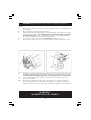
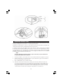
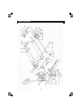
HYDRAULIC PALLET TRUCKS
MODEL Nos: PT550 GAL & PT685 GAL
PART Nos: 7630234 & 7630236
OPERATION & MAINTENANCE
INSTRUCTIONS
0204
Please read these instructions carefully before operating the truck
Thank you for purchasing this CLARKE Strong-Arm Pallet Truck.
Before using the device, please read this manual thoroughly and carefully follow all
instructions given. This is for your own safety and that of others around you, and is also to
help you achieve a long and trouble free service from your new truck.
CLARKE GUARANTEE
This CLARKE product is guaranteed against faulty manufacture for a period
of 12 months from the date of purchase. Please keep your receipt as proof
of purchase.
This guarantee is invalid if the product is found to have been abused or
tampered with in any way, or not used for the purpose for which it was
intended.
Faulty goods should be returned to their place of purchase, no product
can be returned to us without prior permission.
This guarantee does not affect your statutory rights.
PARTS & SERVICE TEL: 020 8988 7400
or e-mail as follows:
PARTS: [email protected]
SERVICE: [email protected]
-2-
CONTENTS
Guarantee ............................................................................. 2
Specifications ........................................................................ 4
Safety Precautions ................................................................ 5
Assembly ................................................................................ 6
Maintenance ........................................................................ 6
Operating Instructions .......................................................... 7
Fault Finding .......................................................................... 8
Parts List & Diagram (Main Frame) ............................ 9 & 10
Parts List & Diagram (Handle & Pump) ................... 11 & 12
Declaration Of Conformity ................................................ 14
The PT550GAL & PT685GAL industrial pallet trucks are built for tough daily
use in factories and warehouses, and operating in damp conditions.
FEATURES
•
Heavy duty steel gauge construction.
•
Tandem fork rollers provide extra stability.
•
3 Position trigger includes neutral for safe handling.
•
Foot and hand lowering controls.
•
Adjustable descent speed control.
•
Chrome plated piston rod, ensuring a longer life.
•
Drop forged lift link arms provide strength and durability.
•
Galvanised Finish.
-3-
SPECIFICATIONS
Model
PT550 GAL
PT685 GAL
Part Number
7630234
7630236
Lifting capacity
2,500 kg
2,500 kg
550mm
685mm
Fork Length
1100mm
1220mm
Fork Width
160mm
160mm
Gap Between Forks
230mm
365mm
4 Way
2 Way
Twin Nylon
Twin Nylon
Galvanised
Galvanised
88 kg
103 kg
Overall Width
Entry Options
Fork Rollers
Finish
Weight
WARNING!
MAXIMUM LOAD - 2500KG
Please note that the details and specifications contained herein are correct at the time of going to
print. However CLARKE International reserve the right to change specifications at any time without
prior notice. Always consult the machines data plate
-4-
SAFETY PRECAUTIONS
•
ALWAYS wear good quality safety shoes, (steel toe caps) and industrial work gloves.
•
ALWAYS ensure the load is evenly distributed on the forks and is perfectly stable
before attempting to raise.
•
ALWAYS before operating, ensure that all bolts, pins and securing devices are correctly
in place and in good condition. Check for signs of cracked welds, bent or loose pins
or other signs of structural damage. Do not use if any of these conditions exist. Ensure
repairs are carried out by qualified persons only, or contact your nearest Clarke
dealer.
•
ALWAYS lower the forks to their lowest position when not in use,, and ensure it is left
where it cannot become a hazard to others. If necessary, the wheels must be
chocked to prevent it from moving and possibly becoming a hazard.
•
ALWAYS ensure the machine is properly maintained at all times (see Maintenance).
•
NEVER turn the tiller at right handles to stop the truck.
•
NEVER exceed the load for which the machine was designed. If the load
capacity and other warning labels become defaced or illegible, have them
replaced.
•
NEVER use the truck to transport persons, or use as a scooter.
•
NEVER use in applications where a risk exceeding the rated capacity exists.
•
NEVER use in applications where a risk of unintentional movement exists.
•
NEVER allow the truck to have direct contact with foodstuffs.
•
NEVER use truck in potentially explosive atmosphere.
•
DO NOT leave load on pallet truck for lengthy periods
•
DO NOT rapid load the truck, i.e.; drop heavy loads directly onto forks.
•
DO NOT allow any person to operate the machine unless they are completely
familiar with all aspects of operation and have read this manual thoroughly.
•
DO NOT use as a vehicle jack
•
DO NOT use the extremity of fork arms as a lever to lift a load.
•
DO NOT exceed the maximum working load for the truck. See Specifications.
•
DO NOT use on gradients due to excessive efforts and loss of control.
•
DO NOT use on rough terrain, floor requirements are, smooth, non slip, hard, level and
without obstacles ONLY.
•
DO NOT transport personnel on the truck, or use as a scooter.
•
DO NOT leave the truck on a gradient without first securely chocking the wheels.
•
DO NOT use if wheels or castors are damaged...have them replaced immediately.
•
DO NOT use in places insufficiently illuminated, (min 50 lux).
•
If the machine has been subjected to an abnormal load or shock, remove it from
service immediately and have it fully inspected by a qualified person. If necessary,
consult your Clarke dealer.
•
The truck must not be altered or modified in any way unless previously authorised by
Clarke International.
IMPORTANT:
ALWAYS check to ensure the centre of gravity of the load is centered about the forks.
-5-
ASSEMBLY Figures in brackets refer to Index Nos in parts list on pages 9-12
Your new Pallet truck is delivered with the handle removed, To fit the handle proceed as
follows;
1.
Remove one roll pin, item 1, Fig. 1 (117) from shaft, item 2, Fig. 1 (118) and keep safe
for reuse later.
2.
Remove shaft from pump body item 4, Fig. 2.
3.
Insert Handle tube with warning label on top and trigger on R/H side, item 3, Fig.2
(108) at position A, Fig. 1, Note ; handle needs to be held at an angle of approx 45º
in order to fit the shaft, connect handle tube to pump body by sliding the shaft,
item 2, Fig. 1, back into pump body and handle tube.
4.
Turn shaft so that the roll pin is vertical. DO NOT push fully home yet.
5.
Pass the roller chain, item 5, Fig. 2 (115), through the centre hole in shaft, Locate
Fig. 1
8.
1a)
2a)
Fig. 2
Try raising the forks by pushing the trigger, item 8, Fig. 3 down until it latches. Pump
handle backwards and forwards, forks should lift. and should remain in up position.
If forks drop without raising the trigger up to the lowering position, proceed as follows.
Loosen hexagonal nut, item 10, Fig. 5 (134) and turn screw, item 9, Fig. 5 (133)
anticlockwise a little.
Repeat step 7, again if forks drop, turn screw a little more, keep repeating this
procedure until forks stay up until, either the trigger or foot pedal is operated to
lower the truck. If forks do not lower when operating the trigger or foot pedal, turn
WARNING!
MAXIMUM LOAD - 2500KG
-6-
Lower
Neutral
8
Raise
Fig. 3
7
9
10
Fig. 5
Fig. 4
OPERATING INSTRUCTIONS
Before operating the truck, ensure you have read and understood the instructions in this
manual, paying particular attention to the safety precautions.
Familiarise yourself with the controls, i.e; raise and lower the forks without any load, practice
steering the empty truck to understand how the truck reacts.
To raise the forks, push the trigger down until it latches, then slowly pump the handle
backwards and forwards and watch the forks lift, once the forks are in their highest position,
put the trigger into the central position (neutral), to lower the forks, gently pull the trigger
upwards, or push the foot pedal down the more the trigger is pulled up or the foot pedal is
pushed down, the faster the forks will lower,
NOTE:
The forks will drop much faster when a load is on the forks, also the heavier the
load the faster still the rate of descent.
!.
Ensure the pallet to be moved does not exceed the maximum weight for the truck.
2.
Make visual checks to ensure the load is secure and will not topple off when lifted,
also check the pallet is not broken etc.
3.
Once satisfied all is ok, proceed as follows.
a)
With the forks in their lowest position, Slowly push the truck under the load to be
moved, try to position the truck so that the centre of gravity is in the middle of the
forks. In the event this is not possible the rated capacity is reduced, ie; the truck is
designed and built to lift a maximum load of 2500 kg spread over both forks. Take
care that the fork rollers are not sitting on any pallet cross member etc.
-7-
b)
Slowly raise the forks and watch the load lift, once the load has been raised
sufficiently, put the trigger in the neutral position (centre), before attempting to
move the truck.
c)
Gently push or pull the pallet truck with load to its new location, observing that
there are no personnel or obstacles in the way.
d)
Before lowering the load, ensure it is clear to do so, i.e.; make sure that nobody’s
feet, including your own are underneath the pallet etc, once satisfied the
way is clear, slowly lower the load to the floor.
e)
Withdraw the pallet truck, Lower the forks to their lowest position and store
safely so as not to cause an obstruction, chock the wheels if necessary to
prevent the truck moving accidentally.
NOTE:
If the truck has not been used for some time, there is a possibility that the hydraulic
system may have absorbed air.
This can easily be removed in the following way:
1. With the trigger pulled up fully (lowering position), quickly pump the handle
backwards and forwards 4 - 6 times.
2. Push trigger down to its lowest position, slowly pump the handle backwards
and forwards, forks should now lift, if not repeat steps 1 & 2 until the forks lift
normally.
MAINTENANCE
Inspect the truck daily for possible cracks/damage, also check for oil leaks. Special
attention Should be paid to the nylon wheels. Check that all wheels and auxiliary rollers
are complete and turn freely, check they are not blocked by anything being wrapped
around the axles, i.e.; threads and rags etc, if any are found they should be removed.
Nuts and bolts etc, if run over can and do get embedded in the nylon wheels, if any
such foreign objects are found, they should be removed.
Approx every three months all moveable joints should be lubricated using a good quality
motor oil, DO NOT apply so much oil that it drips onto the floor.
WARNING!
MAXIMUM LOAD - 2500KG
-8-
PARTS DIAGRAM
-9-
PARTS LIST
Index No
1
2
3
4
5
6
7
8
9
10
11
12
13
14
15
16
17
18
19
20
21
22
23
24
25
26
27
28
29
30
31
32
33
34
36
37
38
39
40
41
42
43
44
45
Part No
ZJB01
ZJB02
ZJB03
ZJB04
ZJB05
BZJ06
ZJB07
ZJB08
ZJB09
ZJB10
ZJB11
ZJB12
ZJB13
ZJB14
ZJB15
ZJB16
ZJB17
ZJB18
ZJB19
ZJB20
ZJB21
ZJB22
ZJB23
ZJB24
ZJB25
ZJB26
ZJB27
ZJB28
ZJB29
ZJB30
ZJB31
ZJB32
ZJB33
ZJB34
ZJB36
ZJB37
ZJB38
ZJB39
ZJB40
ZJB41
ZJB42
ZJB43
ZJB44
ZJB45
Description
Handle and Pump Complete
Large Wheel Shaft
Bolt
Bearing
Supporting Base
Spring Pin
Retaining Ring
Large Wheel
Bearing
Half Cirque
Bowl Washer
Axle Retaining Ring
Dust Cover
Pin
Oiler
Spring Pin
Joint
Pin
Straight Tappet
Long Shaft
Retaining Ring
Oiler
Roll Sheath
Spring Pin
Shaft
Shaft
Spring Pin
Roll Ring
Shaft
Spring Pin
Fork Wheel Frame
Spring Pin
Shaft
frame
Bolt
Sheath
Wheel
Nut
Fork Frame
Spring Lock Washer
Bolt
Rocker Arm
Nut
Fork Wheel
Qty
1
1
1
1
1
2
1
2
8
4
2
2
2
2
8
2
2
2
2
1
2
4
2
2
2
2
2
4
2
2
2
8
4
4
2
2
2
2
1
1
1
1
1
4
IMPORTANT:
The use of parts other than CLARKE replacement parts may result in safety hazards,
decreased tool performance and may invalidate your warranty.
-10-
PARTS DIAGRAM Handle & Pump
PARTS & SERVICE TEL: 020 8988 7400
or e-mail as follows:
PARTS: [email protected]
SERVICE:
[email protected]
-11-
PARTS LIST Handle & Pump
Index No
101
102
103
104
105
106
107
108
109
110
111
112
113
114
115
116
117
118
119
120
121
122
123
124
125
126
127
128
129
130
131
132
133
134
135
136
137
Part No
ZJB101
ZJB102
ZJB103
ZJB104
ZJB105
ZJB106
ZJB107
ZJB108
ZJB109
ZJB110
ZJB111
ZJB112
ZJB113
ZJB114
ZJB115
ZJB116
ZJB117
ZJB118
ZJB119
ZJB120
ZJB121
ZJB122
ZJB123
ZJB124
ZJB125
ZJB126
ZJB127
ZJB128
ZJB129
ZJB130
ZJB131
ZJB132
ZJB133
ZJB134
ZJB135
ZJB136
ZJB137
Description
Blade Spring
Spring Pin
Roller
Spring Pin
Spring Pin
Spring Pin
Handle
Handle Tube
Shaft
Spring Pin
Pressure Roller
Bush
Pull Rod
Bush
Chain
Nut
Spring Pin
Shaft
Plug
Copper Washer
Spring
Damping Valve Spindle
Damping Valve Seat
Steel ball
Base
Copper Washer
Bolt
Spring
Strike Pin
‘O’ Ring
Axle Sleeve
‘O’ Ring
Bolt
Nut
Lever Plate
Bolt
Spring
-12-
Qty
1
2
1
1
1
1
1
1
1
1
1
1
1
1
1
1
2
1
1
2
1
1
1
1
1
2
2
1
1
1
1
1
1
1
1
1
1
TROUBLE SHOOTING
No.
Symptoms
1.
Forks not lifting to
maximum height.
2.
Possible Causes
Insufficient hydraulic oil.
Add more hydraulic oil.
a) No hydraulic oil.
b) The oil is contaminated.
a) Add Hydraulic oil.
b) Change the hydraulic
oil.
c) Slacken locknut (item 10),
turn the regulating screw a
little ant- clockwise. Repeat
adjustment until forks lift OK.
Forks not lifting.
c) The regulating screw
(item 9) Fig.1 is set too
close to strike pin.
3.
4.
5.
The forks do not
lower after raising.
Leaking oil.
Forks drop without
operating the
trigger.
Remedy
a) The regulating screw set
too for back from strike
pin.
b) Piston rod is deformed
due to misuse, ie;
overloading or loading
to one side.
c) The forks not lowered
down fully when not in
use, causing piston to
rust.
a) Oil seals / ‘O’ rings worn
or damaged.
b) Pump body worn or
cracked.
a) Contamination in the
hydraulic oil.
b) Leaking oil.
-13-
a) Adjust regulating screw as
above (turn screw
clockwise).
b) Fit new piston rod and
cylinder.
c) Clean and lubricate piston.
Replace piston and cylinder
if too badly damaged.
a) Replace.
b) Replace.
a) Wash the damping valve
with kerosene and/or
change the hydraulic oil.
b) See above.