1
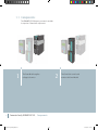
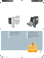
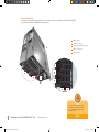
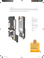
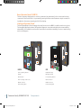
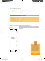
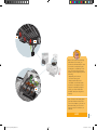
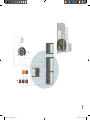
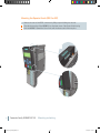
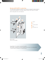
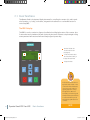
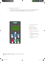
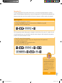
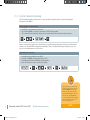
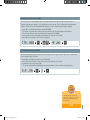
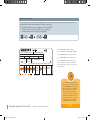
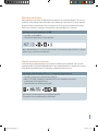
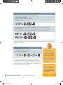
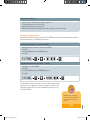
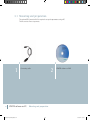
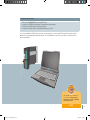
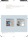
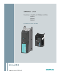
Sinamics G120 Multimedia Training Package www.siemens.com/sinamics-g120 I_DT_G120_Booklet_RZ.indd 1 04.04.2012 13:11:25 Required System Configuration CD-ROM • • • • • Processor with min. 2 GHz (dual core recommended) 1024 MB RAM Graphics card (min. 256 MB memory recommended) Screen resolution: 1280 x 1024 px Operating Systems: Microsoft® Windows™ XP (Service Pack 2 or later) Microsoft® Windows™ Vista Microsoft® Windows™ 7 2 I_DT_G120_Booklet_RZ.indd 2 04.04.2012 13:11:27 SINAMICS G120 Training Booklet This booklet contains the same information as the attached CD. Still, we highly recommend to work through the learning program before consulting the booklet. The multimedia tutorial is a comfortable and easy to understand introduction to the converter family SINAMICS G120. 04/2012 6FC5095-0AA85-0BA0 3 I_DT_G120_Booklet_RZ.indd 3 04.04.2012 13:11:28 Materials and tools The components listed below are presented in this booklet. To test your knowledge on the actual roduct, you have the choice between the following order alternatives: p Training case Product Order no. • SINAMICS G120 training case* 6ZB2480-0CJ00 Single components Product Order no. • SINAMICS G120 PM240-2 FSA 0.55kW 6SL3210-1PE11-8AL0 • SINAMICS G120 CU240E-2 6SL3244-0BB12-1BA1 • Motor (0.55 kW) 1LA7096-4AA10 • SINAMICS PC Connection Kit-2 6SL3255-0AA00-2CA0 • SINAMICS BOP-2 6SL3255-0AA00-4CA1 • Intelligent Operator Panel IOP 6SL3255-0AA00-4JA0 • Screening kit 2 6SL3264-1EA00-0HA0 Optional components Product Order no. • IOP/BOP-2 door mounting kit 6SL3256-0AP00-0JA0 In addition, you will need the following equipment: • • • • PC with USB interface Switches – commercially available* Potentiometer – commercially available* Various M4 screws and nuts (length depends on installation location) with suitable screwdriver/ wrench – commercially available* *T he training case is a complete demo station including a motor, the power module of the converter, switches, lights and a 230 V power supply connection. I_DT_G120_Booklet_RZ.indd 4 04.04.2012 13:11:28 Safety instructions Validity These instructions apply to the following converter: Product SINAMICS G120 Prerequisites You are proficient in working with the Microsoft® Windows™ operating system. You are conversant with the principles of electronics and electrical engineering. Warning Dangerous currents and voltages! The equipment contains dangerous voltages and controls potentially dangerous rotating mechanical parts. Non-compliance with the warnings or failure to follow the instructions contained in the documentation can result in loss of life, severe personal injury or serious damage to property. Take particular notice of the general and regional installation and safety regulations regarding work on dangerous voltage installations (e.g. EN 50178) as well as the relevant regulations regarding the correct use of tools and personal protective equipment (PPE). Qualified Personnel The device/system may only be set up and used in conjunction with this documentation. Commissioning and operation of a device/system may only be performed by qualified personnel. Within the context of the safety notes in this documentation, qualified persons are defined as persons who are authorized to commission, ground and label devices, systems and circuits in accordance with established safety practices and standards. Disclaimer of Liability Depending upon the firmware and software version of the Control Unit, of the Operator Panel and of the STARTER, the masks, symbols and menus may differ. We have reviewed the contents of this publication to ensure consistency with the hardware and software described. Since variance cannot be precluded entirely, we cannot guarantee full consistency. However, the information in this publication is reviewed regularly and any necessary corrections are included in subsequent editions. I_DT_G120_Booklet_RZ.indd 5 04.04.2012 13:11:28 Welcome to the SINAMICS G120 Tutorial for First Time Users. This tutorial will help acquaint you simply, quickly and comfortably with the frequency converter. We’ll take you step by step through installation, setting parameters and initial start-up. We recommend that you don’t skip any chapters. 6 I_DT_G120_Booklet_RZ.indd 6 1 04.04.2012 13:11:28 Converter family SINAMICS G120 08–21 1.1 Components Power Module 12 Control Unit 13 Operator Panel 2 (BOP-2/IOP) 14 Power Module 15 Control Unit 18 Operator Panels (BOP-2/IOP) 20 1.2 Mounting and wiring Operator Panels BOP-2 and IOP 22‒41 2.1 Basic functions The BOP-2 display 24 Menu structure 25 Parameter list 27 Operating pattern 27 Function buttons 29 Resetting the converter 30 Setting the control mode 31 Selecting line frequency 31 Entering motor data 32 Specifying application parameters 33 Saving and restoring data 35 The device 37 Working with IOP 38 2.2 Working with BOP-2 2.3 Quick commissioning 2.4 Intelligent Operator Panel STARTER software and PC 42‒73 3.1 Mounting and preparation Creating a STARTER project 46 STARTER user interface 49 Loading converter data 50 Configuration wizard 54 Safety Integrated 58 Start motor data identification 62 Setting setpoint specifications 65 Saving data 67 Restoring factory settings 70 Download overview 75 3.2 Parameterization 3.3 Application cases Appendix 7 I_DT_G120_Booklet_RZ.indd 7 04.04.2012 13:11:28 This chapter will introduce the low-voltage SINAMICS G120 converter. You’ll learn about the main components, hear about its structure and get some practiceoriented insight about the assembly and wiring of the frequency converter. 8 I_DT_G120_Booklet_RZ.indd 8 1 04.04.2012 13:11:28 Converter family SINAMICS G120 9 I_DT_G120_Booklet_RZ.indd 9 04.04.2012 13:11:34 1.1Components The SINAMICS G120 frequency converter is modular. It comprises of three basic components: 1 10 The Power Module supplies voltage to the motor 2 The Control Unit controls and monitors the Power Module Converter family SINAMICS G120: Components I_DT_G120_Booklet_RZ.indd 10 04.04.2012 13:11:35 3 The Basic Operator Panel (BOP-2) and the Intelligent Operator Panel (IOP) are used to operate and monitor the converter + The optional PC Connection Kit-2 can also be used to set parameters, operate and monitor the converter; the kit is required in order to establish communication between a PC and the Control Unit Each Control Unit can be freely combined with each Power Module. nOTE I_DT_G120_Booklet_RZ.indd 11 11 04.04.2012 13:11:37 Power Module The device is available in several sizes. Its power range is between 0.37 kW and 250 kW. The picture shows the PM240-2 frame size A. 1 1 Rating plate 2 Power connectors 3 Connectors / Braking resistor 4 Motor connectors 5 PE terminals 2 5 2 3 4 3 5 4 Please check the rating plate to make sure that the module also meets your requirement specifications. 12 Converter family SINAMICS G120: Components I_DT_G120_Booklet_RZ.indd 12 Note 04.04.2012 13:11:42 Control Unit There are various designs for the Control Units. They differ primarily in terms of the control terminal assignments as well as in terms of different field bus interfaces. This tutorial will use the example of the CU240E-2 Control Unit. It was developed for stand-alone operation. 8 7 3 1 6 4 2 1 Rating plate 2 DIP switch for analog inputs and fieldbus address 3 Interface for the Operator Panel (BOP-2 or IOP) 4 Status LEDs 5 Terminals for digital and analog inputs and outputs 6 USB interface for STARTER 7 Interface to the Power Module 8 Fastening clips 8 8 5 An overview of the various control unit versions and their differentiation can be found in the official SINAMICS G120 brochure at: http://www.siemens.com/ sinamics-g120/printmaterial Note I_DT_G120_Booklet_RZ.indd 13 13 04.04.2012 13:11:43 Basic Operator Panel 2 (BOP-2) The basic input and display device is used to operate and set parameters for the converter after being connected to the Control Unit. It is operated by pressing the buttons and features a simple commissioning thanks to the menu prompting and the 2-line display. Intelligent Operator Panel The Intelligent Operator Panel manages the same functions as the BOP-2 but adds several more options. The integrated application wizard, full graphical diagnostic overviews and plain text increase usability substantially. It is available in various versions and can be used drive-externally for series commissioning and on-site diagnosis. 3 4 5 2 5 1 6 6 2 4 1 BOP-2 14 IOP 3 1 Seven operating buttons 1 Graphical display 2 Display 2 Navigation wheel 3 Release catch 3 Five operating buttons 4 Door mounting screw recess 4 USB connection 5 RS232 connector 5 RS232 connector 6 Product rating label 6 Product rating label Converter family SINAMICS G120: Components I_DT_G120_Booklet_RZ.indd 14 04.04.2012 13:11:49 1.2Mounting and wiring Before starting assembly, check to ensure the following conditions have been met: • All required components, tools and small parts have been prepared • All required cables and lines have been laid in accordance with specifications • All minimum clearances are being observed The 5 Safety Regulations must be strictly observed • • • • • Disconnect Secure against unintentional restart Verify that it is free of voltage Ground and bypass Cover and shield any adjacent live parts Mounting of the Power Module into the switch cabinet 62.3mm (2.45") Please refer to the drilling pattern accompanying the Power Module for the correct drilling centers and clearance distances above and below the Power Module. 186 mm (7.32") Example of drilling pattern 5.35 mm (0.21") 36.5 mm (1.44") Normally the motor and converter are selected in such a way that they match each other. This is also the case in our example. However, the data from the rating plate of the motor are important for the initial start-up of the converter. Note I_DT_G120_Booklet_RZ.indd 15 15 04.04.2012 13:11:49 Connecting the Power Module to the motor Depending on the operating environment, different cable length limits are required for the connection between the Power Module and motor. Unshielded cables up to 100 m in length are possible in industrial electrical networks. Wiring the Power Module 1 • Connect the phases and the earth conductor to the terminals U2, V2, W2 and PE Wiring the motor 2 • • • • • • • Unscrew the cover to the terminal box on the motor (the inside cover of Siemens’ motors illustrates the possible wiring for the Star connection and the Delta connection) Remove the bridge rails from the connecting block and loosen the screws Place the bridge rails on the terminal block and screw them into place (depending on the type of connections required – Star or Delta, in this example a Star connection is shown) Insert the cables from the Power Module through the opening of the terminal box to the motor Connect the PE connection first Slide the phases in accordance to the phase assignment in the connections Replace the terminal cover and ensure it is secured with the four screws to the required torque The motor and Power Module are now connected. Wiring the power supply 3 • Connect the phases and the earth conductor to the pluggable terminal clamps L1, L2, L3 and PE The electrical wiring is now complete. 16 Converter family SINAMICS G120: Mounting and wiring I_DT_G120_Booklet_RZ.indd 16 04.04.2012 13:11:49 3 1 2 2 Motor lines represent interfering transmitters. As a result, you should use shielded cable in order to meet the corresponding electromagnetic compatibility conditions. The cable lengths that are actually possible depend upon the following: ‒ Operating environment ‒ Converter being used ‒ Reactors and filters used ‒ Shielded or unshielded cable In order to meet Class A electromagnetic compatibility requirements, you need a filter and a shielded cable (max. length: 25 meters). The depicted example shows a Star connection. The rating plate provides information about the correct circuit data: e.g. 230/400 V ∆/Y means that you are connecting the motor in Y with a 400 V network. Note I_DT_G120_Booklet_RZ.indd 17 17 04.04.2012 13:11:54 Attaching the Control Unit Connect the Control Unit with the fastening clips on the bottom of the Power Module and then press the upper edge of the Control Unit against the Power Module until the locking device snaps into place. Before wiring the control terminals, the terminal cover has to be opened. General procedure for wiring with the cage clamp mechanism • Slide the wire into the terminal opening • The inner clamp opens slightly and snaps the wire tightly into place The wire is now firmly attached. • To release the wire press a screw driver onto the lever • Remove the wire • Withdraw the screwdriver from the terminal Wiring the control terminals in the CU240E-2 1 The potentiometer: • Attach the positive pole of the supply voltage to 1 • Attach the negative pole to 2 • Wire the output of the potentiometer arm to 3 • Close the circuit by connecting 4 with negative pole 2 2 On/Off, Reverse, and Reset buttons: • Wire the button’s power supply to 9 • Attach the associated digital inputs to terminals 5, 6 and 7 • To close the circuit, connect 28 and 69 to 34 3 Indicator lamps: • Connect 9 with 20 and 21 to attach the power supply for the LEDs • Wire the Faults LED to digital output 19 and the Warning LED to digital output 22 • Connect the negative pole to terminal 28 4 Display for frequency output: • Connect the positive pole to 12 • Connect the negative pole to 13 The wiring is now complete. 18 Converter family SINAMICS G120: Mounting and wiring I_DT_G120_Booklet_RZ.indd 18 04.04.2012 13:11:55 4 1 3 2 19 I_DT_G120_Booklet_RZ.indd 19 04.04.2012 13:11:58 Mounting the Operator Panels (BOP-2 or IOP) • Remove the cover of the RS232 connection by lifting it up and sliding it to the side • Place the bottom edge of the IOP/BOP-2 into the lower recess of the Control Unit housing 2 • Push the IOP/BOP-2 toward the Control Unit until the release-catch clicks into place 1 2 1 20 Converter family SINAMICS G120: Mounting and wiring I_DT_G120_Booklet_RZ.indd 20 04.04.2012 13:12:02 Mounting the IOP or BOP-2 in a cabinet door The operator panels can simply be mounted in a control cabinet door with just a few manual operations using the optionally available door mounting kit. Degree of protection IP55 / UL type 12 is achieved when mounting them in the control cabinet door. 1 3 4 2 5 1 Door panel 2 Seal 3 Door mounting bracket 4 Screws 5 D-type retaining screws Mounting the IOP Identical mounting with BOP-2 Congratulations! Your converter is now ready for operation. After assembly is completed, the converter’s parameters must be set up, i.e., you must give the converter the specific characteristics of the attached motor. 21 I_DT_G120_Booklet_RZ.indd 21 04.04.2012 13:12:03 In this section, you will learn more about the usage of Operator Panels to control the converter locally on-site. You’ll learn how to use the Basic Operator Panel 2 ( BOP-2) to set up parameters for the converter and the attached motor and how to operate the converter with the BOP-2. Then, you will learn how to use the Intelligent Operator Panel (IOP) to your advantage. 22 I_DT_G120_Booklet_RZ.indd 22 2 04.04.2012 13:12:03 Basic Operator Panel (BOP-2) Intelligent Operator Panel (IOP) 23 I_DT_G120_Booklet_RZ.indd 23 04.04.2012 13:12:11 2.1 Basic functions The Operator Panel is the input and display instrument for controlling the converter. It is used in standalone operation, i.e., locally, on the device, integrated in the cabinet door or as handheld version for series setup (IOP). The BOP-2 display The BOP-2 is used to commission, diagnose (troubleshoot) and display the status of the converter. Up to 2 status values can be simultaneously and continuously monitored. It features a simple navigation using a transparent and well-structured menu and clearly assigned operator keys. 1 2 1 Menu bar indicates the selected menu function (see page 25) 2 Provides information about the selected functionality or displays the actual value 3 Displays the values 3 In this tutorial, we introduce an application that is based on “V/f control with linear characteristic curve”. This control method is typically applied for conveyor belt applications. We recommend that you work through the example we have presented here in order to familiarize yourself with setting up parameters for a converter. 24 Operator Panels BOP-2 and IOP: Basic functions I_DT_G120_Booklet_RZ.indd 24 Note 04.04.2012 13:12:12 Menu structure When moving the menu bar to the following menu function, the following applies: 1 1 2 3 4 5 6 MONITORING The actual status of the converter/motor system is displayed 2 CONTROL Setpoint, Jog and Reverse mode can be activated 3 DIAGNOSTICS Faults and alarms can be acknowledged, history and status is displayed 4 PARAMETER Parameter values can be viewed and changed 5 SETUP Basic commissioning of the converter can be performed 6 EXTRAS Additional functions such as saving and copying data sets into and from the BOP-2 can be performed 25 I_DT_G120_Booklet_RZ.indd 25 04.04.2012 13:12:12 2.2 Working with BOP-2 The BOP-2 has got seven buttons. For setup and parameterization only the UP and DOWN, OK and ESC buttons are relevant. The ON, OFF and HAND/AUTO keys are needed for local operation. 1 ESC key – Takes you back to the previous screen 2 Up key – Change selection 3 Down key – Change selection 4 OK key – Confirm the selection 5 OFF key – Stops the motor in manual mode 6 HAND / AUTO key – Switches the c ommand source between HAND and AUTO mode 7 ON / RUN key – Starts the Motor in manual mode 2 4 1 3 5 26 6 7 Operator Panels BOP-2 and IOP: Working with BOP-2 I_DT_G120_Booklet_RZ.indd 26 04.04.2012 13:12:12 Parameter list To better understand the functionality of the buttons, you should be acquainted with the operating pattern: The Basic Operator Panel gives you access to a parameter list. Stored behind the parameters are parameter values that control the operation of the motor. However, not all the numbers are assigned. Operating pattern Example • Press ESC to enter the menu selection • Use the UP and DOWN buttons to move the menu bar to PARAMS and press OK • Press OK to select the Standard Level ESC OK The first parameter number that appears is displayed on the left side of the screen: r2 (r stands for read only and means that you can only read this value but cannot change it). On the right side, the parameter value of the selected number is shown. Example • • • • • Press UP to access the next parameter In this case, P3 appears (P means that you can change the value of this parameter) Press OK to edit the parameter Use the UP and DOWN buttons to adjust the value Confirm the value by pressing OK ESC OK OK OK If you want to change any parameter using the parameter list, you are requested to choose a filter level (Standard or Expert). The Standard Level limits the available parameters, thus limiting the risk of dangerous parameters. The Expert Level gives access to all parameters. Note I_DT_G120_Booklet_RZ.indd 27 27 04.04.2012 13:12:13 Some parameters store more than one value. In this case, pressing OK does not take you directly to the value, but to an index that is displayed in brackets [00] above the actual value. Example for index parameters Example • • • • • • • Pressing OK takes you to [00] UP takes you to [01], DOWN back to [00] Decide for an index number of your choice Press OK again to edit the index The value starts flashing Adjust the value by pressing UP and DOWN Confirm by pressing OK OK OK OK A complete list of all parameters can be found in the “Parameter Manual: Control Units – CU240E/B-2” as a download at: http://support.automation. siemens.com/WW/view/ en/49946755 If you want to adjust any blinking/active value digit by digit (using the UP and DOWN button might just take too long), you can always press the OK button longer than two seconds. After releasing the button, you can change any single digit by using the buttons OK (move to next digit), ESC (move to previous digit), UP (increase value), and DOWN (decrease value). 28 Operator Panels BOP-2 and IOP: Working with BOP-2 I_DT_G120_Booklet_RZ.indd 28 Note 04.04.2012 13:12:13 Function buttons With the function buttons, you can actually operate the motor. The HAND/AUTO button changes the command source between the BOP-2 (HAND) and field bus (AUTO). A hand icon appears in the screen to indicate HAND mode is active. • • • • • In HAND mode the ON and OFF buttons are enabled In AUTO mode the ON and OFF buttons are disabled If HAND mode is active, pressing the HAND/AUTO button will switch the converter to AUTO mode If AUTO mode is active, pressing the HAND/AUTO button will switch the converter to HAND mode Changing HAND to AUTO mode is possible while the motor is still running Screen Icons The BOP-2 displays a number of icons at the left-hand side of the display to indicate the actual state of the converter. • Command source auto / hand • Converter status running • JOG JOG • Fault / Alarms active A detailed list of the Fault and Alarm messages can be found in the “Parameter Manual: Control Units – CU240E/B-2” as a download at: http://support. automation.siemens.com/WW/ view/en/49946755 Note I_DT_G120_Booklet_RZ.indd 29 29 04.04.2012 13:12:13 2.3 Quick commissioning The following descriptions show how to set up the drive using the quick commissioning wizard integrated in the BOP-2. Starting quick commissioning • Press ESC to enter the menu selection • Use UP and DOWN to move the menu bar to SETUP and press OK • The screen will automatically display the next parameter in the commissioning sequence ESC OK Quick commissioning begins now. It will help you set all relevant parameters step by step. Parameters that are not relevant will be skipped automatically. Thus, you adjust the factory settings of your converter to the requirements of your motor. Resetting the converter • • • • Press OK while the BOP-2 shows RESET Press UP or DOWN to change the value to YES Press OK and wait until the BUSY sign disappears Now all values are reset to the factory setting OK OK Any step of the commissioning wizard can be skipped by pressing the DOWN button. Going back one step can be done by pressing the UP button. By confirming one step with OK, the screen will automatically display the next parameter in the commissioning sequence. 30 Operator Panels BOP-2 and IOP: Quick commissioning I_DT_G120_Booklet_RZ.indd 30 Note 04.04.2012 13:12:13 Setting the control mode (P1300) In our example it is assumed that your converter and the motor are new. As a result, a series of preparatory steps are required, e.g. selecting the control mode. This is indicated by the parameter umber 1300. ‘V/f control with linear characteristic curve’ is defined by the factory setting. n • • • • • Press OK to modify the parameter value CTRL MOD The upper row shows the control mode associated to the actual parameter value below Choose your desired control mode value by pressing UP or DOWN See how the control mode name in the upper row changes accordingly Press OK if the desired control mode is displayed OK OK Selecting line frequency (P100) The next parameter sequence sets the line frequency of the region in which the motor is being used. In our example, this is Europe. • • • • Press OK to modify the parameter value EUR USA Set 0 for Europe (50 Hz) (1 represents the US line frequency of 60 Hz) Confirm the value by pressing OK The screen will automatically display the next parameter in the commissioning sequence OK OK The applicable line frequency can be also found on your motor plate (see chapter “Entering motor data”). Note I_DT_G120_Booklet_RZ.indd 31 31 04.04.2012 13:12:13 Entering motor data In the next step, the converter is adjusted to the motor. The motor data can be found on the motor’s rating plate. Please set the values according to the plate. • Press OK to edit the motor voltage stored under P304 • The preset motor voltage of 400 volts is displayed • Leave the value and confirm by pressing OK OK OK OK D-91056 Erlangen 3~Mot. 1LE10011AC434AA0 E0807/0496382_02 003 IEC/EN 60034 100L IMB3 IP55 25 kg Th.Cl. 155(F) -20°C Tamb 40°C UNIREX-N3 Bearing DE 6206-2ZC3 15g Intervall: 4000hrs NE 6206-2ZC3 11g SF 1.15 CONT NEMA MG1-12 TEFC Design A 2.0 HP 60Hz: Hz A kW PF NOM.EFF rpm CL V A V 50 3.5 1.5 0.73 84.5% 400 970 380 - 420 3.55-3.55 0.73 84.5% 970 660 - 725 2.05-2.05 690 Y 50 2.05 1.5 60 3.15 1.5 0.69 86.5% 1175 K 460 1 2 3 4 1 P304 = MOT VOLT = Motor voltage 2 P100 = EUR USA = Standard IEC or NEMA 3 P305 = MOT CURR = Motor rated current 4 P307 = MOT POW = Motor rated power 5 P311 = MOT RPM = Motor rated speed The line frequency has been set already in the beginning of quick commissioning (see page 31.) 5 If you want to adjust any flashing value digit by digit (using the UP and DOWN button might just take too long) press the OK button longer than two seconds. After releasing the button, you can change each single digit by using the buttons OK (move to next digit), ESC (move to previous digit), UP (increase value) and DOWN (decrease value). 32 Operator Panels BOP-2 and IOP: Quick commissioning I_DT_G120_Booklet_RZ.indd 32 Note 04.04.2012 13:12:17 Motor data identification After entering the motor data, the wizards asks to activate the motor data identification. This is recommended for a live verification and optimization of the data that you have entered. The motor data identification initiates a “measurement” of the connected motor. In the process, the data previously calculated in the converter are compared to the actual motor data and adapted to one another. Activating motor data identification (P1900) • Press OK to confirm MOT ID • Change the displayed value to 1 by pressing UP OK Motor data identification does only start after the basic commissioning sequence has been completed and the motor is switched on the first time! Specifying application parameters In the next step, pre-defined settings for the converter’s interfaces can be activated. This is stored in parameter number 15 and indicated by MAc PAr for macro parameterization. For example, the converter offers different pre-defined macros for setting the command and setpoint source. Activating pre-defined settings (P15) e.g. for command and setpoint source • • • Press OK to activate macro parameterization MAc PAr Macro 12 (Std ASP) is displayed, it determines DI 0 for the command source and the potentiometer for the setpoint source Leave the value and confirm by pressing OK OK OK The converter can now be turned on using digital input DI 0. The setpoint source is specified as the potentiometer. 33 I_DT_G120_Booklet_RZ.indd 33 04.04.2012 13:12:17 Minimum frequency, ramp up and ramp down time (P1080) • • • • Set the minimum frequency under parameter MIN RPM Press OK (Parameter MIN RPM) Change the value by pressing UP or DOWN Press OK to confirm OK OK • Set the ramping-up time under parameter RAMP UP for acceleration time to maximum frequency (P1120) • Set the ramping-down time under parameter RAMP DWN for time until standstill (P1121) OK OK OK OK The values are displayed in seconds. In both cases, the times indicated should not be too short, because this might result in an alarm. Completing quick commissioning • Press OK while the BOP-2 shows FINISH • Select YES and press OK again OK OK The converter is now parameterized optimally to your application and motor specifications. Now motor data identification should be performed to finalize the commissioning. This can be done by switching on the motor. At the moment, command source is set to digital input DI 0. Start the motor with turning on DI 0. 34 Operator Panels BOP-2 and IOP: Quick commissioning I_DT_G120_Booklet_RZ.indd 34 Changing the value digit by digit is possible by pressing the OK button longer than 2 seconds. After releasing the button, each single digit can be changed by using the buttons OK (move to next digit), ESC (move to previous digit), UP (increase value) and DOWN (decrease value). Refer to the “Parameter Manual: Control Units – CU240E/B-2” for a description of the control modes and their corresponding parameter settings at: http://support. automation.siemens.com/WW/ view/en/49946755 Note 04.04.2012 13:12:17 Motor data identification • • • • Start the motor manually by using digital input DI 0 The measuring process is set in motion When finished, the motor switches off BOP-2 indicates that the measured values are now being converted into data Saving and restoring data Saving data in different location is important. The EXTRAS function allows loading parameter data from the converter memory to the BOP-2 and vice versa. Saving parameter sets from converter to BOP-2 • • • • Navigate with the menu bar to the function EXTRAS Press OK Push the DOWN button until TO BOP appears Press OK OK OK Copying parameter sets from BOP-2 to converter • • • • Navigate to the menu EXTRAS Press OK Push the DOWN button until FROM BOP appears Press OK OK OK The Basic Operator Panel 2 can also be used to make a variety of other adjustments to your application. Please note that an overview of the parameter numbers can be found in the Operating Instructions: Control Units CU240E-2. The BOP-2 can be mounted or removed at any time. The device is not necessary for ongoing operation. Note I_DT_G120_Booklet_RZ.indd 35 35 04.04.2012 13:12:17 2.4Intelligent Operator Panel With the Intelligent Operator Panel, you can set the inverter parameters, put the inverter into operation, monitor the ongoing operation of the motor, and get valuable information about faults and alarms. All these functions can be accessed without expert knowledge. The main advantages are as follows: Fast commissioning without expert knowledge • • • • • Simple commissioning of standard applications using application-specific assistants, no knowledge of parameter structure necessary User customized parameter lists with reduced parameter sets Simple local commissioning using the handheld version Fast multiple commissioning with clone function Commissioning without documentation by using the integrated help function Minimization of maintenance time • • • Diagnosis with clear text display, without documentation usable on site Simple update of languages, application assistants and firmware using the integrated USB connection Integrated clear text help function to read and resolve fault messages and reasons locally High usability, intuitive handling • • • • Direct, manual control of the drive – simple switching from local to remote operation Intuitive menu navigation using wheel-click interface Graphical display for i.e. status values in vertical-bar charts (for example pressure or flow rate) Status display with freely selectable units – display of real, physical values Flexible usage • • • • 36 Available for direct control unit mounting, for door mounting or as handheld version (depending on frequency converter type) Simple and fast mechanical and electrical door mounting Handheld usable for a large variety of frequency converters 5 integrated languages Operator Panels BOP-2 and IOP: Intelligent Operator Panel I_DT_G120_Booklet_RZ.indd 36 04.04.2012 13:12:17 The device The IOP is a menu-driven device. Its functionality is structured by three options: 1 2 1 [Wizards] Assists you to set up standard applications 2 [Control] Allows you to change setpoint value, turning direction activates the jog function in real-time 3 [Menu] Gives you access to all possible functionalities 3 The display All necessary information is user-friendly displayed in plain text or icons. The displayed icons are shown at the top right-hand edge of the display. They indicate various states of the converter. • Command source auto / hand • Inverter status ready / running • Fault • Alarm pending • Battery condition Fully Charged / Discharged 37 I_DT_G120_Booklet_RZ.indd 37 04.04.2012 13:12:18 Working with IOP The IOP is operated mainly by using the push-wheel. The five additional buttons make it possible to display certain values or to switch between manual and auto mode. The buttons are called: ON key, OFF key, ESC key, Info key and HAND/AUTO key. 4 5 1 3 6 1 Turning changes the selection Pressing confirms the selection 2 Starts the motor in manual mode 3 Stops the motor in manual mode 4 Takes you back to the previous screen 5 Displays additional information 6 Switches the command source between HAND and AUTO mode 2 The HAND/AUTO function works identically to the one implemented in the BOP-2. After starting the motor with the ON button, you can change the setpoint speed by navigating to CONTROL/SETPOINT and turning the wheel (right to increase speed, left to decrease speed). 38 Operator Panels BOP-2 and IOP: Intelligent Operator Panel I_DT_G120_Booklet_RZ.indd 38 Note 04.04.2012 13:12:18 The wizards There are several wizards which allow you to set up various functions and commission the converter. They navigate you interactively through the parameterization of standard applications. The wizards are accessed from the wizard menu, at the bottom-left of the status screen. Example: Basic commissioning • • • • Use the wheel to highlight the word WIZARDS Confirm by pressing OK Navigate to BASIC COMMISSIONING by turning the wheel Confirm by pressing OK OK Wizards OK OK Basic Commissioning OK Now the wizard will guide you step by step through the basic commissioning process by presenting a number of screens where you can choose the necessary options and values. At the conclusion of the basic commissioning process, the data can be saved to the converters memory, and calculation of motor and control data is started. • Always use the wheel to select an option and press OK to confirm • Press ESC to move back one step • Press INFO to read context-sensitive help information On the top of the screen, you can see numbers that indicate the present step of the wizard that you are in. 2/15 for example means that you are in step 2 of 15. Note I_DT_G120_Booklet_RZ.indd 39 39 04.04.2012 13:12:18 Accessing diagnostics If you want to find out which input and output devices are connected to the converter, simply navigate to the diagnostics menu and select the I/O STATUS. This option displays a list of the digital and analog inputs and outputs of the converter. In addition, you can monitor their current status. This is an information screen and cannot be changed. Reading the I/O status • • • • • • • • Use the wheel to highlight the word MENU Confirm by pressing OK Select DIAGNOSTICS Confirm by pressing OK Choose I/O STATUS Confirm by pressing OK Choose STATUS DIGITAL INPUTS Confirm by pressing OK OK Menu OK OK OK I/O Status OK OK Diagnostics OK Status Digital Inputs OK You can now see a clearly arranged overview of all connected I/O including their status. Using the button INFO, always gives you more in-depth information on the presently highlighted parameter, step or feature. 40 Operator Panels BOP-2 and IOP: Intelligent Operator Panel I_DT_G120_Booklet_RZ.indd 40 Note 04.04.2012 13:12:18 Getting information on active faults • • • • • Use the wheel to highlight the word MENU Confirm by pressing OK Choose DIAGNOSTICS Confirm by pressing OK Select ACTIVE FAULTS/ALARMS OK OK Menu OK OK Active Faults/Alarms Diagnostics OK OK Now, all active fault messages that have not yet been acknowledged are displayed. To get further information, you can highlight each one and press INFO. You now know how to use the Operator Panels to set the parameters on your converter and start it up. A further possibility is setting up the parameters using your PC or a SIMATIC programming device. This method is clearer and more convenient, but requires somewhat more preparation time. If you want to find out about previous faults and alarms, please navigate back one level and select “History”. This will display a list of all previous faults and alarms including the time they occurred. Note I_DT_G120_Booklet_RZ.indd 41 41 04.04.2012 13:12:18 In the next step, you will learn how to connect your PC or PG to the converter and how to set parameters with the STARTER software. With STARTER, you can also easily activate the Safety Integrated functions of the drive. 42 I_DT_G120_Booklet_RZ.indd 42 3 04.04.2012 13:12:18 STARTER software and PC 43 I_DT_G120_Booklet_RZ.indd 43 04.04.2012 13:12:26 3.1Mounting and preparation The optional PC Connection Kit 2 is required to set up the parameters using a PC. The kit consists of two components. 1 44 Connecting cable 2 STARTER software on DVD STARTER software and PC: Mounting and preparation I_DT_G120_Booklet_RZ.indd 44 04.04.2012 13:12:26 Hardware preparation • • • • Place the STARTER DVD into your DVD drive Install the STARTER software by following the setup wizard Connect the USB cable to the Control Unit Connect the other end to the USB interface of your PC You must install the USB driver if you are connecting the converter and PC together for the first time. Windows 7 automatically installs the driver; for older Windows versions, you must confirm the automatic installation. The STARTER is also available as a download at: http://support. automation.siemens.com/WW/ view/en/26233208 Note I_DT_G120_Booklet_RZ.indd 45 45 04.04.2012 13:12:27 Creating a STARTER project After installation is complete, switch on the converter’s power supply and start the program. The project wizard opens automatically. The wizard will help you create your first project. 1 Select “Find drive units online” 2 Give the project a name and click “Continue” 1 46 2 STARTER software and PC: Mounting and preparation I_DT_G120_Booklet_RZ.indd 46 04.04.2012 13:12:27 3 Check that “DEVICE” is set as Access point. If not, choose “Access point ...” and set “DEVICE” in the dialog box “Set Access Point for Accessible Nodes”. Check that “S7USB” is set as interface. If not, choose “PG/PC ...”. 4 Open the drop-down menu “Access Point of the Application” 5 Choose the command “DEVICE (STARTER – SCOUT) --> S7USB” 6 In “Interface Parameter Assignment Used” select “S7USB” 7 Close with OK 3 4 5 6 7 47 I_DT_G120_Booklet_RZ.indd 47 04.04.2012 13:12:34 8 The identified converter is displayed 9 Add the converter to your project with “Insert drive units” 10 Close the project wizard with “Complete” The converter is now integrated into the project tree and the parameters can be set up using the STARTER software. 8 10 9 48 STARTER software and PC: Mounting and preparation I_DT_G120_Booklet_RZ.indd 48 04.04.2012 13:12:40 STARTER user interface 1 Project tree 2 Program menu 3 Toolbar with special features 4 Icon “Connect to selected target devices” 5 Connection mode 6 Work area 2 4 3 1 6 5 49 I_DT_G120_Booklet_RZ.indd 49 04.04.2012 13:12:41 Loading converter data Before you can load the current converter’s data into your project, an online connection between the PC and the converter has to be established. 1 Click the icon “Connect to selected target devices” 2 Set the access point to “DEVICE” and place a checkmark next to converter name 3 Click “Load HW configuration to PG” 2 1 3 50 STARTER software and PC: Mounting and preparation I_DT_G120_Booklet_RZ.indd 50 04.04.2012 13:12:46 Now the converter data is loaded into the project and an online connection between PC and converter is established. 4 The blue highlighted “Offline mode” changes to the yellow highlighted “Online mode” 5 The workbench area opens Workbench area The area provides additional information such as alarms, the target system output and the d iagnostics overview. It also stores additional operating features. 5 4 51 I_DT_G120_Booklet_RZ.indd 51 04.04.2012 13:12:46 3.2Parameterization You can now begin to parameterize your converter. 1 Double-click on the converter icon in the project tree 2 Click on “Load CPU / drive unit to PG” 2 1 52 2 STARTER software and PC: Parameterization I_DT_G120_Booklet_RZ.indd 52 04.04.2012 13:12:50 3 Double-click “Configuration” 4 Click “Wizard ...” in the work area and let the wizard guide you 3 4 We recommend parameterizing our example using the online mode. Note I_DT_G120_Booklet_RZ.indd 53 53 04.04.2012 13:12:52 Configuration wizard The configuration wizard guides you step by step through the following parameters: • • • • • • • • • Control structure Defaults of the setpoint source and the command source Drive setting Motor Motor data Drive functions Important parameters Calculation of the motor data Summary By clicking “Next” you get to the next configuration step. 1 54 2 STARTER software and PC: Parameterization I_DT_G120_Booklet_RZ.indd 54 04.04.2012 13:12:54 1 Start by setting the control structure 2 Define the command and setpoint source 3 Select the motor type 4 Input motor data corresponding to the rating plate 3 4 For non-Siemens motors, please use the motor rating plate to input the motor data. Note I_DT_G120_Booklet_RZ.indd 55 55 04.04.2012 13:12:57 5 Select “Identify motor data at standstill” for motor data identification 6 Enter maximum current 7 Enter minimum and maximum speed 8 Enter ramp-up, ramp-down time and OFF3 ramp-down time emergency shut-off 5 6 7 8 56 STARTER software and PC: Parameterization I_DT_G120_Booklet_RZ.indd 56 04.04.2012 13:13:00 After clicking “Next”, the calculating of the motor data starts. This concludes the parameterization with the configuration wizard. You will now receive a summary of all parameter values input. The summary can be inserted into a text file by pressing the “Copy text to clipboard” button. Finally select “Copy RAM to ROM” to store the parameterization in the converters ROM memory and close the window by clicking “Finish”. 57 I_DT_G120_Booklet_RZ.indd 57 04.04.2012 13:13:07 Safety Integrated If your converter is used in a safety related environment, we strongly recommend performing Safety Integrated engineering using the STARTER. STARTER guides you clearly and easily through the process. Thus, the risk of wrong parameterization is reduced to a minimum. All control units CU240E-2 come with the Safety Integrated function STO (Safe Torque Off). STO can be used when the motor can decelerate to a standstill within a short period of time. Activating the STO function, immediately ensures that the motor cannot supply any further torque-generating energy. Advantages for the user: • No wearing parts thanks to electronic shutdown • Converter remains connected to the supply, it always supports full diagnostics capability • Password protected, no manipulation of the function possible v STO t The CU240E-2_F and CU240E-2_ DP-F Control Units have several Safety functions integrated. In this case, no encoder is needed. Detailed information about SINAMICS Safety Integrated are available at: www.siemens.com/ safety-integrated 58 STARTER software and PC: Parameterization I_DT_G120_Booklet_RZ.indd 58 Note 04.04.2012 13:13:08 Activating Safety Integrated 1 Browse to “Safety Integrated” in the project tree 2 Select “Change settings” 3 Choose ”STO via terminal” from the drop-down menu 2 3 3 1 Did you know that extended SINAMICS Safety Integrated functions can be used without the need of an encoder at the motor? This worldwide unique feature saves installation and engineering time, reduces system costs and saves space. For further instructions consult the Safety functional manual SINAMICS G120 and SINAMICS G120C using the Siemens Product Information System (Prodis) at: http://support.automation. siemens.com/WW/view/ en/50736819 Note I_DT_G120_Booklet_RZ.indd 59 59 04.04.2012 13:13:10 4 If your converter is connected to a controller, set the output signal to “STO active” in the corresponding drop-down menu 5 Click on “extended settings” for further adjustments 6 Follow the STARTER instructions 5 60 6 4 STARTER software and PC: Parameterization I_DT_G120_Booklet_RZ.indd 60 04.04.2012 13:13:12 Now your first Safety channel is set. For the second channel just copy the parameters. Clicking “Activate settings” concludes the safety engineering. In the workbench area click on “Alarms” and press the “Acknowledge” button to activate the actually safety functions. 61 I_DT_G120_Booklet_RZ.indd 61 04.04.2012 13:13:15 Start motor data identification 1 2 1 Open the “Commissioning” entry in the project tree 2 Double-click “Control panel” in the project tree 3 Click on “Assume control priority!” in the workbench area 4 A setup window for command transfer opens, accept the displayed values and safety instructions 4 4 3 The pending motor data identification is indicated by the message “A7991” in the alarm tab. The message tells you that motor data identification will be performed after switching the motor on. 62 STARTER software and PC: Parameterization I_DT_G120_Booklet_RZ.indd 62 Note 04.04.2012 13:13:18 5 Place a checkmark next to “Enables” in the workbench area Now the STARTER software has control authority for the attached motor. 6 Click the green button to start the motor 5 6 63 I_DT_G120_Booklet_RZ.indd 63 04.04.2012 13:13:27 Motor data identification is processed. Parameter setup has been successfully completed when Alarm 7991 has disappeared. 64 STARTER software and PC: Parameterization I_DT_G120_Booklet_RZ.indd 64 04.04.2012 13:13:29 3.3Application cases Before returning control authority from the STARTER software to the terminal, you should try controlling the motor from the PC. Setting setpoint specifications 1 Input 1.500 rpm in the “setpoint specification” box 2 Click the green button to start the motor 3 See how the motor runs with 1.500 rpm 1 3 2 65 I_DT_G120_Booklet_RZ.indd 65 04.04.2012 13:13:42 4 Adjust the speed with the slider 5 Click the red button to stop the motor 6 Conclude the process by clicking “Give up control priority!” All functions from the displayed control area in the STARTER will be deactivated. The control authority has been returned to the terminal. 4 6 66 5 STARTER software and PC: Application cases I_DT_G120_Booklet_RZ.indd 66 04.04.2012 13:13:54 Saving data A power outage may cause the loss of the parameter settings. As a result, STARTER offers various possibilities for protecting your parameter settings. 1 Double-click the “Drive navigator” in the project tree 2 Select “Commissioning” in the work area 1 2 67 I_DT_G120_Booklet_RZ.indd 67 04.04.2012 13:13:57 3 Select “Save data in drive (RAM to ROM)” to store the parameter settings in the converter’s EEPROM memory 3 68 STARTER software and PC: Application cases I_DT_G120_Booklet_RZ.indd 68 04.04.2012 13:14:06 Because you have worked in online mode, no data whatsoever have been stored in your project. 4 Click “Save data to project” to save the parameter setting in your project Now you could disconnect the online connection to the converter by clicking the “Disconnect from target system” icon. In our example, please continue to remain online to restore the converter to its factory settings. 4 69 I_DT_G120_Booklet_RZ.indd 69 04.04.2012 13:14:08 Restoring factory settings Resetting your converter to factory settings might be helpful if you have experienced any problems during parameterization. 1 Double-click the “Drive navigator” 2 Select “Commissioning” 1 2 70 STARTER software and PC: Application cases I_DT_G120_Booklet_RZ.indd 70 04.04.2012 13:14:10 3 Click “Factory settings” The security query that is now displayed lets you know that all settings you have made will be reset. Using the checkbox query, you will have the opportunity to save your settings to the converter’s ROM memory beforehand. 3 71 I_DT_G120_Booklet_RZ.indd 71 04.04.2012 13:14:12 4 Click “OK” to reset all converter settings to the factory setting 4 72 STARTER software and PC: Application cases I_DT_G120_Booklet_RZ.indd 72 04.04.2012 13:14:20 5 After reset click “Disconnect from target system” You now know how to use STARTER to quickly and clearly insert your converter into a project, set up its parameters, and put it into operation. Please make sure that you always remember to save the parameter data to the converter and in the software before exiting a project. 5 73 I_DT_G120_Booklet_RZ.indd 73 04.04.2012 13:14:28 Congratulations! You have mastered the SINAMICS G120 Training Booklet. Thank you for your time and efforts. We hope that this tutorial has addressed all the questions you had and was useful to you. More detailed information can be found online. 74 I_DT_G120_Booklet_RZ.indd 74 04.04.2012 13:14:30 Download overview Overview of the various control unit versions http://www.siemens.com/sinamics-g120/printmaterial SINAMICS G120 brochure Additional information on parameters http://support.automation.siemens.com/WW/view/en/49946755 “Parameter Manual: Control Units – CU240B/E-2” Detailed information about SINAMICS G120 http://support.automation.siemens.com/WW/view/en/50815575 “Operating Instructions: SINAMICS G120 Inverter with CU240B-2 and CU240E-Control Units” Safety Integrated Function Manual http://support.automation.siemens.com/WW/view/en/50736819 STARTER software http://support.automation.siemens.com/WW/view/en/26233208 75 I_DT_G120_Booklet_RZ.indd 75 04.04.2012 13:14:32 Siemens AG Industry Sector Drive Technologies Motion Control Subject to change Order No.: 6FC5095-0AA85-0BA0 Dispo: 21200 04/2012 HL 11076147 EN Printed in Germany © Siemens AG 2012 I_DT_G120_Booklet_RZ.indd 76 04.04.2012 13:11:24