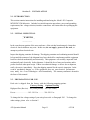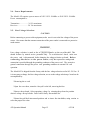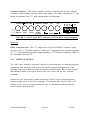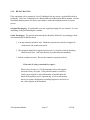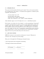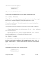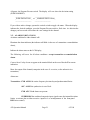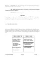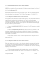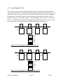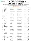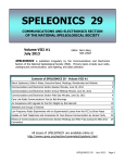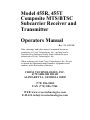
1
Model 455R, 455T
Composite MTS/BTSC
Subcarrier Receiver and
Transmitter
Operators Manual
Rev 2.2 6/25/98
Data, drawings, and other material contained herein are
proprietary to Cross Technologies, Inc., and may not be
reproduced or duplicated in any form without the prior
permission of Cross Technologies, Inc.
When ordering parts from Cross Technologies, Inc., be sure
to include the equipment model number, equipment serial
number, and a description of the part.
CROSS TECHNOLOGIES, INC.
6170 SHILOH ROAD
ALPHARETTA, GEORGIA 30005
(770) 886-8005
FAX (770) 886-7964
WEB www.crosstechnologies.com
E-MAIL [email protected]
Model 455R, 455T Composite MTS/BTSC Subcarrier Receiver and
Transmitter Operators Manual
TABLE of CONTENTS
SECTION
TITLE
PAGE
Warranty........................................................4
OPERATORS SAFETY CONSIDERATIONS................5
1
GENERAL INFORMATION ................................. 7
1-1. INTRODUCTION ........................................................... 7
1-2. SPECIFICATIONS .......................................................... 7
1-3. SAFETY CONSIDERATIONS ............................................ 7
1-4. GENERAL DESCRIPTION ................................................ 10
2
INSTALLATION ............................................ 11
2-1. INTRODUCTION ........................................................... 11
2-2. INITIAL INSPECTION .................................................... 11
2-3. PREPARATION FOR USE ................................................ 11
2-4.
Power Requirements ..................................................... 12
2-5.
Line Voltage Selection ................................................... 12
2-6.
Power Cable ............................................................... 13
2-7. OPERATING ENVIRONMENT ........................................... 13
2-8. RACK MOUNTING ........................................................ 13
2-9. REMOTE & ALARM CONNECTIONS .................................. 13
2-10.
Remote Control Interface Information ................................ 14
2-11. VIDEO BASEBAND CONNECTIONS ................................. 14
2-12. COMPOSITE/STEREO/SAP/PRO/MONITOR CONNECTIONS.... 15
2-13. VIDEO FILTERING ....................................................... 16
2-14. REPACKAGING ........................................................... 17
455 Operation Manual
Page 2
6/23/98
TABLE of CONTENTS
SECTION
3
TITLE
PAGE
OPERATION ................................................ 18
3-1. INTRODUCTION ........................................................... 18
3-2. APPLYING POWER ........................................................ 18
3-3. CONTROL SWITCHES .................................................... 19
3-4. STATUS CHANGES ....................................................... 19
3-5. ALARM INDICATIONS ................................................... 21
3-6. TROUBLESHOOTING .................................................... 22
4
ADJUSTMENTS and OPTIONS ........................... 26
4-1. INTRODUCTION ........................................................... 26
4-2. RECOMMENDED TEST EQUIPMENT ................................. 26
4-3. TRANSMITTER FRONT PANEL ADJUSTMENTS .................. 27
4-4.
Level Adjustment (IF) ................................................... 27
4-5.
Deviation Adjustment (DEV) ........................................... 28
4-6.
Use of the Overmodulation Indicator .................................. 30
4-7. RECEIVER FRONT PANEL ADJUSTMENTS ........................ 30
4-8.
Squelch Adjustment ...................................................... 31
4-9.
Composite Level Adjustment ........................................... 32
4-10. TRANSMITTER INTERNAL OPTIONS ............................... 32
4-11. RECEIVER INTERNAL OPTIONS ..................................... 32
4-12.
Input High Pass Filter .................................................. 33
455 Operation Manual
Page 3
6/23/98
WARRANTY
This Cross Technologies product is warranted against defects in material and workmanship for one
year from the date of shipment. During this period Cross Technologies will either repair or
replace, at its option, products which prove to be defective.
To obtain service under this warranty, this product must be returned to Cross Technologies at its
address. Buyer shall pay all shipping charges to Cross Technologies, and Cross Technologies
shall pay all charges for return shipment to buyer. When this product is to be returned from
outside the United States, buyer shall pay all shipping charges, taxes, duties or other reasonable or
necessary costs to transport the product safely in both directions.
LIMITATIONS AND EXCLUSIONS
This warranty shall not apply to defects resulting directly or indirectly from any of the following:
Improper or inadequate maintenance.
User-supplied interfacing or connected equipment.
Operation beyond the specifications of the unit or under severe
environmental conditions.
Improper facility preparation or maintenance.
No other warranty is expressed or implied. Cross Technologies specifically
disclaims any implied warranties of merchantability or fitness for any particular
purpose. Under no circumstances shall Cross Technologies be liable for any
incidental, indirect or consequential damages or losses, whether or not Cross
Technologies has any advance notice of the possibility of such damages.
Correspondence:
CROSS TECHNOLOGIES, INC.
6170 Shiloh Road, Alpharetta, GA 30005
Telephone (770) 886-8005
E-mail [email protected]
FAX (770) 886-7964
455 Operation Manual
Page 4
6/23/98
OPERATORS SAFETY CONSIDERATIONS
General
The general safety information in this documentation is for operating and servicing personnel.
Specific warnings and cautions will be found throughout the manual where they apply and may or
may not appear here.
Safety Symbols
___________
_ WARNING _
___________
WARNING symbols indicate a condition, practice or procedure that, if not properly performed or
adhered to, could result in personal injury or loss of life.
CAUTION
CAUTION symbols indicate a condition, practice or procedure that, if not properly performed or
adhered to, could result in damage to the equipment or other property.
Before Applying Power
CAUTION
Verify that the voltage selection on the power receptacle matches the line voltage and the proper
fuse is installed. See Section 2.
___________
_ WARNING _
___________
This equipment is grounded through the grounding
conductor of the power cord supplied with the unit. To
avoid electrical shock, plug the power cord into a properly
wired receptacle. An uninterruptible safety earth ground
must be provided from the main power source to the
equipment via the power cord. Grounding one conductor of
a two conductor wiring system or cord is not sufficient
protection.
455 Operation Manual
Page 5
6/23/98
OPERATORS SAFETY CONSIDERATIONS
(Cont'd.)
___________
_ WARNING _
___________
Danger From Loss of Protective Ground
Upon loss of the protective ground connection, all accessible
conductive parts can render an electrical shock.
Do Not Remove Covers or Panels
To avoid personal injury or shock, equipment should not be
operated without covers or panels.
Servicing
Servicing instructions are for the use of qualified servicing
personnel only. Some adjustments described in this manual
are performed with power applied to the equipment and the
cover removed. To avoid dangerous shock, only qualified
service personnel should perform maintenance.
LCD Display Module
The LCD Display Module mounted in the front panel is
fragile. Care should be taken not to break the exposed glass
panel. If broken, extreme caution should be used to avoid
cuts from sharp edges. If the liquid crystal material touches
your skin or clothes, wash it off immediately using soap and
plenty of water. Do not allow any of the liquid crystal
material to get in your mouth.
455 Operation Manual
Page 6
6/23/98
Section 1 - GENERAL INFORMATION
1-1. INTRODUCTION.
This manual contains information necessary for the installation, operation, testing and alignment
of the Model 455 FM Subcarrier. The documentation for this product is divided into five sections
as described below.
Section 1.General Information: provides general information about this equipment, circuit
description and specifications.
Section 2.Installation: provides installation information including initial inspection, installation
and repackaging the equipment.
Section 3.Operation: provides information about front panel checks and settings.
Section 4.Adjustment & Options: provides information to adjust the equipment, and to select
the various options.
1-2. SPECIFICATIONS.
The specifications are listed in Table 1-1. These are performance standards to which the
Model 455 is aligned and tested.
1-3. SAFETY CONSIDERATIONS.
Safety information, relating to installation, testing, etc. is found throughout this manual. Please
refer to OPERATORS SAFETY CONSIDERATIONS at the beginning of this manu
CROSS TECHNOLOGIES INC.
DEV
IF
PROGRAM
ALARM
A
B
EXECUTE
CROSS TECHNOLOGIES INC.
SQUELCH
AUDIO
PROGRAM
ALARM
A
B
EXECUTE
FIGURE 1-1 Model 455 Subcarrier Transmitter and Receiver
455 Operation Manual
Page 7
6/23/98
TABLE 1-1 - SPECIFICATIONS
System Characteristics:
Subcarrier frequency range......Frequency agile from 1.0 MHz to 9.99 MHz in 10 kHz steps
Frequency response..............±0.1 dB from 20Hz to 70kHz; ±0.5 dB from 70kHz to 120kHz
Total harmonic distortion..........<0.05% at 1 kHz (De-emphasized, 30kHz bandwidth)
Long term stability (6 months)....±0.1 dB at 25°C; ±0.25 dB, 0-50°C
Channel spacing (minimum).......280 kHz for narrow deviation; 600 kHz for wide deviation
Remote control input...............User selectable for on/off or alternate frequency selection
Power requirement.................115/230 VAC (47-63 Hz) <20 VA
Storage temperature range..........-40°C to +70°C
Operating temperature range........0°C to +51°C
Mechanical dimensions............44.4mm (1.75")H x 483mm (19")W x 381mm (15")D, each
Modulator Characteristics:
Nominal deviation for 1V rms (2.828V p-p) inputs:
Input
Deviation Setting
Wide
Narrow
Composite.............................±150.0kHz
±73kHz
Stereo..................................±113.0kHz
±55kHz
SAP......................................±30.8kHz
±15kHz
Pro.........................................±6.2kHz
±3kHz
455 Operation Manual
Page 8
6/23/98
TABLE 1-1 - SPECIFICATIONS (Cont'd.)
Subcarrier output level.................75 to 300 mV P/P (adj.)
Output impedance......................Bridging (≥3 kΩ) to 75Ω line
Front panel adjustments/settings.............Deviation
Subcarrier Level
Subcarrier Frequency
Deviation Range Wide/Narrow
Channel On/Off
Remote Control Mode / Alternate Frequency
Front panel visual indications................Subcarrier Frequency
Alarm and On/Off Status
Overmodulation
Remote Active
Connector type.......................(7) BNC Female plus
5 position modular terminal strip for remote and alarms
Demodulator Characteristics
Composite output level............1.0 V rms for ±150 kHz deviation (wide)
or ±73 kHz deviation (narrow)
Subcarrier input level...............1 mV to 500 mV P/P
Input impedance.................Bridging (≥4 kΩ) to 75Ω line
Front panel adjustments/settings.............Squelch Level
Composite Output Level
Subcarrier Frequency
Channel On/Off
Remote Control Mode / Alternate Frequency
Front panel visual indications.................Subcarrier Frequency
Alarm and On/Off Status
Remote Active
Connector type......................(3) BNC Female plus
5 position modular terminal strip for remote and alarms
455 Operation Manual
Page 9
6/23/98
1-4. GENERAL DESCRIPTION.
The 455 Composite Subcarrier System is engineered to provide a transparent path for the
complete MTS/BTSC composite signal over any video microwave system. With its extremely
low distortion (less than 0.05% at 1kHz), flat frequency response from 20Hz to 120kHz, and
outstanding long-term stability, the 455 has almost no measurable effect on stereo audio
performance.
Both the modulator and the demodulator are fully frequency synthesized and microprocessor
controlled for ease of operation and the ultimate in versatility. All of the critical operating
parameters, as well as any alarm conditions, are displayed on the front panel LCD. Any operating
frequency from 1 MHz to 9.99 MHz can be selected from the front panel. Also selected from
the front panel is a choice of "wide" or "narrow" deviation settings. The wide setting is used to
provide optimum signal-to-noise performance for STL applications, while the narrow setting
provides BTSC broadcast standard compatibility which (with the unit set to 4.50 MHz) can be
used for direct feeds to cable systems or low power transmitter facilities. In spite of this
convenient user interface, a number of safeguards make it nearly impossible to change the
settings of the unit by accident. A built in non-volatile memory device retains the most recent
configuration of the unit during temporary power outages or even prolonged storage without
power.
A remote control input is provided which can be used to either turn the channel on or off, or to
switch the operating frequency. This feature is extremely useful for redundant or backup system
configurations, and, like all of the 455's features, can be easily configured from the front
panel.
The 455 demodulator incorporates Tectan's patented threshold extension FM detector. This
unique circuit permits the 455 to flawlessly track the incoming FM signal under severe noise
conditions which render other receivers useless. This detector design is also inherently stable
with respect to both amplitude and phase, without resorting to complicated automatic modulation
control circuits.
The video baseband is combined with the subcarrier signals in the transmitter by a low component
count passive directional coupler. This circuit has been designed to put virtually no load on the
video line (≥3 KΩ), allowing multiple units to be "daisy-chained" without adversely affecting the
signals on the baseband. The low component count and passive nature of this circuit provide
excellent protection against disruption of the baseband due to component failure or loss of power
in the 455.
455 Operation Manual
Page 10
6/23/98
Section 2 - INSTALLATION
2-1. INTRODUCTION.
This section contains instructions for installing and interfacing the Model 455 Composite
MTS/BTSC FM Subcarrier. Included are initial inspection procedures, power and grounding
requirements, line voltage selection, interface connections and instructions for repackaging the
equipment.
2-2. INITIAL INSPECTION.
___________
_ WARNING _
___________
In the event that any portion of the outer enclosure of the unit has been damaged, a hazardous
electrical shock condition may exist. In this case, do not apply power to the unit, or
attempt to perform electrical tests.
Inspect the shipping container for damage. The shipping container and cushioning material should
be kept until the contents of the shipment have been checked for completeness and the equipment
has been checked mechanically and electrically. This equipment was carefully inspected both
mechanically and electrically before shipment. It should be free of mars and scratches and in
perfect electrical order upon receipt. If there is mechanical damage or defect due to shipment,
notify the carrier immediately. Keep the shipping material for the carrier's inspection. In the
event of mechanical damage, or if the equipment does not pass electrical performance
tests, notify the Cross Technologies office immediately. The warranty statement is located in
the front of this manual.
2-3. PREPARATION FOR USE.
Each unit is shipped from the factory with the following strapping options:
Factory Setting Optional Setting
Highpass filter (Receive) .. IN (Video present) .. OUT (no Video)
Power ........................105-130 Vac .......... 210-250 Vac
To change the line voltage setting of your unit, please refer to Paragraph 2-5. To change the
other settings, please refer to Section 5.
455 Operation Manual
Page 11
6/23/98
2-4. Power Requirements.
The Model 455 requires a power source of 105V-130V 50-60Hz or 210V-250V 50-60Hz.
Power consumption is:
Transmitter.................. 24 VA maximum.
Receiver..................... 20 VA maximum.
2-5. Line Voltage Selection.
CAUTION
Before connecting ac power to this equipment, make sure it is set to the line voltage of the power
source. Also ensure that the common connection of the power outlet is connected to a protective
earth contact.
___________
_ WARNING _
___________
Line voltage selection is made at the ac plug-in receptacle on the rear of the shelf. This
should be done by trained service personnel only. To avoid electrical shock, make sure
the power cord is disconnected before changing the voltage selection pc board. Before
connecting this device to the power source, verify that a protective earth ground
connection is provided through the grounding conductor of the power cord. The protective
ground connection through the power cord grounding conductor is essential for safe
operation.
The Model 455 is shipped from the factory with the line voltage selection set for 105-130 Vac. If
it is necessary to change the line voltage selection, access to the voltage selection pc board can be
accomplished by:
*Removing the ac cord.
*Open the cover door, rotate the fuse-pull to the left, removing the fuse.
*Remove the pc board. Select operating voltage by orienting the pc board to position
desired voltage on top-left side. Push board firmly into module slot.
*Rotate fuse-pull back into normal position and re-insert fuse into holder, using caution to
select the proper fuse value.
455 Operation Manual
Page 12
6/23/98
Fig. 2.1 AC Connector
2-6. Power Cable.
In accordance with safety standards, this equipment is supplied with a three conductor cable.
When connected to an appropriate power line outlet, this cable grounds the equipment cabinet.
2-7. OPERATING ENVIRONMENT.
The operating environment should be within the following limitations:
Temperature........................ 0 °C to +50 °C
Humidity........................... 95% maximum non-condensing
Altitude........................... 3050 meters (10,000 ft.) ASL
2-8. RACK MOUNTING.
The Model 455 is intended for rack mounting in a rack having an EIA standard width of 482.6
mm (19 inches). It is shipped from the factory with the mounting brackets set for flush
mounting. Optionally the mounting brackets can be reversed for extended mounting (5
inches). Four 12-24 screws are required for mounting in the rack.
2-9. REMOTE & ALARM CONNECTIONS.
Remote control and alarm connections are made at the 5 position terminal block on the rear of the
equipment. A thin-bladed flat screwdriver is required. Connections are made as marked on the
rear panel. Terminals will accept wire sizes up to 12 AWG maximum.
455 Operation Manual
Page 13
6/23/98
BTSC
COMPOSITE
MONITOR
BASE BAND
LOOP THRU
INPUT
OUTPUT
BTSC
COMPOSITE STEREO
IN (XMT)
OUT (RCV)
SAP
I NPUTS
PRO
N
O
C
O N
M C
R
M
T
ALM
FIGURE 2-2 455 Rear Panel
2-10. Remote Control Interface Information.
The 455 remote control input is capable of switching the unit to an alternate configuration which
the user has pre-programmed (see Section 3-4 for set-up information). The alternate configuration
can differ from the normal configuration in any or all of the parameters which can be set using
the front panel switches (ON/OFF, Frequency, WIDE/NARROW Deviation).
The remote input has a 10kΩ nominal internal pull-up resistor to +5V. An input of less than +2V
selects REMOTE, and an input of greater than +3V selects LOCAL. Because of the internal pullup resistor, an open circuit condition also selects LOCAL. The connecting circuit should be
capable of sinking at least -200µA to assure a logical low condition to select remote. Most
commercial logic devices (including TTL & CMOS) are compatible with this input.
CAUTION
Do not exceed the following maximum ratings for the remote control input:
MAXIMUM INPUT VOLTAGE:
+60 VDC
MINIMUM INPUT VOLTAGE:
-60 VDC
Although the remote input has excellent high frequency noise immunity due to an internal filter,
low frequency noise on long lines may cause inadvertent switching. Shielded cables are
recommended for all applications, or, if long distances or high noise environments are
expected, balanced line drivers and receivers should be used.
2-11. VIDEO BASEBAND CONNECTIONS.
Video baseband connections are BNC connectors on the rear of the shelf. A detailed description
of the connections are:
Transmitter:
Input - Video input from video source. If video is not used this port should be terminated with
455 Operation Manual
Page 14
6/23/98
75Ω. In multiple- unit operation, the input of units after the first is connected to the output of the
preceding unit.
Output - Composite output to microwave or satellite transmitter. In multiple unit
operation, the output of all but the last unit connects to the input of subsequent units.
Receiver:
Input - Composite input from microwave or satellite receiver. In multiple-unit operation, the
input of units after the first is connected to the output of the preceding unit.
Output - Video output to monitor or video receiving equipment. If video is not used, this port
should be terminated with 75Ω. In multiple unit operation, the output of all but the last unit
connects to the input of subsequent units.
2-12. COMPOSITE/STEREO/SAP/PRO/MONITOR CONNECTIONS.
These connections are BNC connectors on the rear of the shelf. A detailed description of the
connections are:
Transmitter:
BTSC Composite - InThis 75Ω input is designed to accept the output of a BTSC composite
generator which has built-in SAP and PRO channel generators, or which provides combining
inputs for separate generators. The 100% modulation level for this input is 1V RMS (2.8V
p-p). If this input is used, the alternate inputs listed below should not be used.
Stereo Input - This 75Ω input is designed to accept the output of a BTSC stereo generator
which does not have built-in SAP and PRO channel generators or which does not have
combining inputs for separate generators. The 100% modulation level for this input is 1V RMS
(2.8V p-p).
SAP Input - This 75Ω input is designed to accept the output of a separate SAP Channel
generator. The 100% modulation level for this input is 1V RMS (2.8V p-p).
PRO Input - This 75Ω input is designed to accept the output of a separate Professional
Channel generator. The 100% modulation level for this input is 1V RMS (2.8V p-p).
455 Operation Manual
Page 15
6/23/98
Composite Monitor - This output connector provides a monitor point for the combined
modulation signal resulting from the various input signals. The output impedance is 75Ω and
should be terminated with 75Ω when measurements are being made.
BTSC
COMPOSITE
MONITOR
BASE BAND
LOOP THRU
INPUT
OUTPUT
BTSC
COMPOSITE
STEREO
IN (XMT)
OUT (RCV)
SAP
I NPUTS
PRO
N
O
C
O N
M C
R
M
T
ALM
FIGURE 2 -3 455 TX and RX Connectors (RX has BTSC Inputs plugged)
Receiver:
BTSC Composite Out - This 75Ω output is the recovered MTS/BTSC composite signal
from the receiver. The output should be connected to equipment having an input impedance
of 75Ω; if the connecting equipment is high impedance, a 75Ω termination should be added at
the end furthest from the 455.
2-13. VIDEO FILTERING.
The video source should be adequately filtered to prevent harmonics or other high frequency
components from interfering with the low level subcarrier signals in the upper part of the
baseband. If the video signal source does not include a suitable lowpass filter, a video lowpass
filter should be added to the system between the video source and the first subcarrier
transmitter.
At the receive site, video quality is improved by using a filter to remove the high frequency
subcarrier signals prior to the video equipment. If an adequate video lowpass filter is not
included in the video receiving equipment, one may be added between the last subcarrier
receiver and the video equipment.
455 Operation Manual
Page 16
6/23/98
2-14. REPACKAGING.
If the equipment is to be returned to Cross Technologies for any reason, care should be taken in
packaging. Call Cross Technologies for a Return Material Authorization (RMA) number. Enclose
documents detailing reason for return, return address, name and telephone number of contact
person.
Original Packaging. It is preferable to use the original packaging if it was retained. Use care
in packing, sealing and marking the container.
Other Packaging. The general instructions below should be followed if re-packaging is done
with commercially available material.
1. A strong container should be used. Minimum requirement would be of singlewall
construction, 200 pound test material.
2. The equipment should be wrapped in plastic with 3 to 4 inches of shock absorbing
material on all sides. Anti-static material is preferred but not mandatory.
3. Seal the container securely. Be sure the container is properly marked.
If the unit is being returned for repair:
Please refer to Section 3-6, Troubleshooting, before returning the
unit to the factory for repair. If the problem cannot be remedied
locally, please include as much information as possible about the
nature of the problem you are experiencing, as well as information
about your system configuration, including frequencies and levels of
the various signals on the baseband.
455 Operation Manual
Page 17
6/23/98
Section 3 - OPERATION
3-1. INTRODUCTION.
This section describes operation of the front panel controls. There are three operator switches,
the LCD display and an alarm indicator. All functions for the equipment are controlled by these
components. The functions are:
1.Turn the channel "on" or "off".
2.Set the frequency of the channel.
3.Select the "wide" or "narrow" deviation mode.
4.Setup these parameters for the remotely activated configuration.
Alarm indications appear on the LCD display but are not controlled by the operator.
Both hardware and software have been designed to make reprogramming as "tamper proof"
as possible. The Program/Execute switch is recessed so it will not inadvertently be operated. All
program changes must start with the operation of the Program/Execute switch and must
also end with the operation of the Program/Execute switch. If this sequence is not followed,
none of the changes will take effect. If programming is initiated and no operator action takes
place for approximately 12 seconds (before the final press of the Program/Execute switch) the
display will revert to its previous status and you will need to start over.
3-2. APPLYING POWER.
NOTE:The last status of a unit is retained even when power is removed. When power is
restored, the unit will return to it's previous settings.
When power is first applied, the LCD display goes through four steps.
1.The LCD goes black to show all segments are functioning.
2.The display will show the unit model number.
__________________
__________________
_455 Transmitter _ or _455 Receiver _
__________________
__________________
455 Operation Manual
Page 18
6/23/98
3.The software version will be displayed.
__________________
_Software Rev #.#_
__________________
4.The present status of the channel is shown.
The unit is now operational and ready for any changes the operator may desire.
3-3. CONTROL SWITCHES.
1.Program/Execute. Any change to the programming of the unit must be initiated by pressing the
Program/Execute switch and completed by pressing the Program/Execute switch.
2.Cursor Movement - Horizontal. This switch is mounted so its movement is horizontal and
moves the cursor left or right.
3.Vertical Switch. This switch is mounted so its movement is vertical and has two functions:
A)During frequency changes, the vertical movement will raise or lower the frequency
in the direction of the arrows.
B)For other functions such as on/off or compandor disable, the vertical switch will
alternately turn the function on or off regardless of the direction operated.
3-4. STATUS CHANGES.
At any time during the modification process, if you have made a mistake and do not wish to save
the changes you have made, do not press the Program/Execute switch; simply do
nothing for approximately 12 seconds, and the system will return to the normal operating
mode.
To modify the status of a channel:
1.Operate the Program/Execute switch. The display will read:
__________________
_MODIFY LOCAL _
__________________
455 Operation Manual
Page 19
6/23/98
Pressing the Up/Down switch (in either direction) will toggle the display to:
__________________
_MODIFY REMOTE _
__________________
When the display indicates the configuration (local or remote) to be modified, press the
Program/Execute switch.
2.Status of the selected configuration will be displayed. For example:
__________________
_L 6.60MHz ON _
__________________
The display consists of:
An initial letter indicates Local or Remote.
The current frequency setting.
The current ON/OFF status.
3.By using the horizontal rocker switch the cursor can be moved left or right to either the
ON/OFF position or to any digit of the frequency.
A.If ON/OFF is selected, the status can be modified by operating the vertical switch. This
will alternately turn the channel on or off.
B.If changes are desired in the frequency, move the cursor to the digit that you wish to
modify. By using the vertical switch, that digit can be raised or lowered by the direction of
the arrow. The cursor can then be moved to another digit and the action repeated until the desired
frequency is displayed.
NOTE:
The modified frequency and ON/OFF condition will not become effective until the final
operation of the Program/Execute switch described in the next paragraph. To prevent
interruption of other channels when a frequency change takes place, the 455
automatically mutes the carrier until the phase locked loop frequency synthesizer has stabilized
at the new frequency.
455 Operation Manual
Page 20
6/23/98
4.Operate the Program/Execute switch. The display will now show the deviation setting
(WIDE/NARROW):
__________________
__________________
_WIDE DEVIATION _ or _NARROW DEVIATION_
__________________
__________________
If you wish to make a change, operate the vertical switch to toggle the status. When the display
indicates the desired condition, press the Program/Execute switch a final time. At this time the
changes you have made will become the new settings for the channel.
3-5. ALARM INDICATIONS.
An alarm condition for either channel will:
Illuminate the alarm indicator (the indicator will blink in the case of a transmitter overmodulation
alarm),
Indicate the alarm status on the LCD display,
The following will occur for all alarm conditions except transmitter overmodulation
alarm:
Cause a form C relay closure to appear at the terminal block on the rear of the shelf for remote
indication.
Mute the output of the channel (composite in the case of a receiver, or the subcarrier in a
transmitter).
Alarms are:
Transmitter: CXR ALMif the carrier frequency deviates beyond predetermined limits.
AFC ALMif the synthesizer is out of lock.
CXR AFCif both alarms are present.
OVERMODif the combined composite input signals cause the internal deviation
limiter to activate (due to either excessive input level or misadjustment of the front panel
DEViation control).
455 Operation Manual
Page 21
6/23/98
Receiver:
CXR ALM upon a drop in incoming carrier level beyond the squelch setting or
the RF/IF section of the receiver is defective.
AFC ALM if the incoming carrier is off frequency or if the frequency determining
elements of the receiver are defective.
CXR AFC if both alarms are present.
CAUTION
An annoying remote alarm can be disabled by turning the channel "off". If this is done there
will be no alarm condition active to remind maintenance personnel there is a problem. The
channel may be brought on-line by someone unaware of the existing problem.
3-6. TROUBLESHOOTING.
In the event of difficulty with the 455 Subcarrier System, the following list of possible causes
should be reviewed prior to contacting the factory for repair. In the event that factory repair is
deemed necessary, please refer to Section 2-14, Repackaging, for information on returning the
unit.
Audio sound quality not
acceptable. Symptoms
could include one or
more of the following:
High distortion
Poor frequency resp.
Sounds noisy
Transmitter set to "wide"
deviation with receiver
set for "narrow" deviation.
Combined composite signal
at the transmitter inputs
may be excessive.
Transmitter DEViation
control misadjusted.
Receiver may also indicate an AFC alarm
intermittently.
455 Operation Manual
Page 22
6/23/98
Audio is noisy, but
sounds normal in other
respects.
Transmission path noise may
be excessive. Check other
system components, RF power,
and antenna pointing.
In non-video systems, if the
subcarrier frequency is less
than about 4.5MHz, the high
pass filter in the receiver
may not be set OUT. (See
Section 5-17.)
Audio sounds noisy.
Tones, chirps, buzz, etc
may also be present.
Channel spacing may be too
close. The 455 requires 600
kHz ("wide") or 280kHz
("narrow") between adjacent
center frequencies to meet
all specifications. At
closer spacings some of
these symptoms may appear.
The subcarrier channel may
be co-located with one of
the harmonics of a video
signal component (e.g.,
colorburst). Shift subcarrier frequencies and reevaluate.
Total baseband power may be
too high, leading to intermodulation products. Reduce
the level of the subcarriers
and/or video and reevaluate.
In systems with video, the
high pass filter in the receiver may be set OUT.
(See Section 5-17.)
455 Operation Manual
Page 23
6/23/98
Composite level and/or
carrier deviation too
high or low.
LCD display blank.
LCD display shows:
NV Memory Error
Receiver LCD display
indicates a CXR alarm.
Verify correct equipment
impedances and terminations.
Loss of power. Possible
causes include blown fuse,
incorrect line voltage
selection, etc. (See
Section 2-5.)
A checksum error was found
after reading the nonvolatile memory device.
The unit may still be used
(press the Program/Execute
switch to proceed) but
should be returned for
repair as soon as convenient
since a power interruption
may cause loss of the unit's
programmed settings.
Receiver may be set to an
incorrect frequency, or the
transmit site may not be
operating on the specified
frequency.
Receiver SQUELCH adjustment
may need to be changed.
(See Section 5-7)
The subcarrier transmitter
for the specified frequency
may not be operating, or may
be at a reduced carrier
level.
455 Operation Manual
Page 24
6/23/98
Receiver LCD display
indicates an AFC alarm.
Any of the situations described above for a CXR
alarm may, under some conditions, also cause an AFC
alarm.
The receiver may be tuned to
a wide deviation channel
which it is unable to track.
LCD display is garbled
or inconsistent with
normal operation.
Ribbon cable connecting
display circuit board to the
main circuit board may have
come loose due to rough handling in shipping. See Section 5-13 to remove cover.
Carefully align cable and
press firmly into socket on
main circuit board.
Socketed integrated circuit
devices may have come loose
due to rough handling in
shipping. See Section 5-13
to remove cover. Firmly
press these devices to seat
them in their sockets (particularly U1, U6, & U9 which
are located behind and to
the right of the display.
455 Operation Manual
Page 25
6/23/98
Section 4 - ADJUSTMENTS and OPTIONS
4-1. INTRODUCTION.
This section describes operator adjustments and the selection of the internal options. For a
discussion of the microprocessor-controlled functions (Channel ON/OFF, FREQUENCY and
compandor IN/OUT) please refer to Section 3-4. For a discussion of line voltage selection,
please refer to Section 2-5. The operator adjustments are located on the front panel on both the
transmitter and receiver. The transmitter adjustments consist of subcarrier level and deviation
trims. The receiver adjustments consist of squelch threshold and composite output level trims.
The only internal option on the 455 is the selection of the receive high pass filter. This option
is set at the factory to IN, and should only changed if the system is used below 4.0 MHz in the
absence of video.
4-2. RECOMMENDED TEST EQUIPMENT.
Note:
The equipment listed below comprises all of the test equipment mentioned in this section. It is not
necessary to have all of these items on hand to perform the adjustments. Refer to each subsection
for the specific items needed.
Item
Manufacturer & Model
Audio Analyzer ........................... HP 8903B
Modulation Monitor ...................... Marconi TF2300A
AC Voltmeter ............................. Fluke 8920A
Spectrum Analyzer ........................HP 8552B/8553B
Frequency Selective VM.................. HP 3586C
Oscilloscope ............................... Tektronix 2235
75Ω 1% BNC Termination .............. Any
25Ω 1% 50Ω to 75Ω series adapter .... Any
Equivalent equipment is acceptable. The specifications of the alternate instrument should
always be significantly better than the desired accuracy of the measurement to be made.
455 Operation Manual
Page 26
6/23/98
4-3. TRANSMITTER FRONT PANEL ADJUSTMENTS.
NOTE:Prior to setting levels be sure transmitter is ON and set to proper frequency. See Section 3.
4-4. Level Adjustment (IF).
Determine the desired subcarrier level for your specific system. The 455 Transmitter subcarrier
level can be adjusted over the range of 75 mV to 300 mV p/p (approx. -8 TO -20 dB, 75Ω).
A. Level Adjustment Without Video or Other Channels.
If it is possible to set the subcarrier level with all other signals (i.e., video and all other subcarriers)
removed from the baseband, the desired subcarrier level may be set directly using an
oscilloscope or wideband AC voltmeter. If it is necessary to adjust the subcarrier level in a "live"
circuit with video and/or other subcarriers present, proceed to the method described in Paragraph
B., below; otherwise, proceed as follows:
1.Connect the BASEBAND INPUT BNC connector of the 455 Transmitter to a suitable
75Ω termination.
2.Connect the BASEBAND OUTPUT BNC connector of the 455 Transmitter to the
measuring instrument (either an oscilloscope or wideband AC voltmeter). If the measuring
instrument has a high impedance input (normally the case), this line should also be terminated
with a suitable 75Ω termination.
3.Adjust the IF (subcarrier level) screwdriver adjustment on the front panel for the
proper system level.
B. Level Adjustment With Video and/or Other Channels.
When other signals (such as video or other subcarrier channels) are present on the baseband,
it is necessary to use a measuring instrument that can be tuned to the desired signal (such as a
spectrum analyzer, frequency selective level meter, or modulation meter with level measuring
capability). Proceed as follows:
1.If the measuring instrument has a high impedance input, connect it to the baseband
signal at any convenient point after the insertion of the subcarrier to be adjusted. If the
455 Operation Manual
Page 27
6/23/98
measuring instrument has a low impedance (i.e., 75Ω or 50Ω) it is necessary to connect the
instrument to an isolated monitor point in order to prevent the additional load presented by the
low impedance input from affecting the level to be measured.
2.With the measuring instrument properly tuned to the frequency of the channel to be
adjusted, set the IF (subcarrier level) screwdriver adjustment on the front panel for the proper
level for your system.
4-5. Deviation Adjustment (DEV).
The 455 Transmitter is designed to operate with a maximum peak deviation of the subcarrier of
150 kHz (300 kHz peak-to-peak) in the "wide" mode, and 73 kHz (146 kHz peak-to-peak) in
the "narrow" mode. A built-in limiter limits peak subcarrier deviation to approximately 168
kHz in the "wide" mode, and 82 kHz in the "narrow" mode. This deviation is a result of the
entire composite signal consisting of L+R, L-R, pilot, SAP, and PRO channels.
If your stereo generator has a built-in Bessel null calibration tone, it may be used
to accurately set the deviation of the 455 Transmitter in the "narrow" deviation mode. This mode
may be used even if you intend to use the "wide" deviation setting in your application.
Switching from "narrow" to "wide" will maintain the deviation calibration within
approximately one percent.
The inputs on the 455 are designed to accept 2.828V p-p signals for 100% modulation levels.
The deviations assigned to the various inputs are as follows:
Input
Deviation Setting
Wide
Narrow
Composite........................... ±150.0kHz ±73kHz (L+R, pilot, L-R, SAP, PRO)
Stereo.............................. ±113.0kHz
±55kHz
SAP.................................. ±30.8kHz
±15kHz
PRO................................... ±6.2kHz
±3kHz
(L+R, pilot, L-R)
If your BTSC stereo generator can be adjusted to provide the required signal level (2.828V pp), it is recommended that the 455 DEV control be left unchanged from the factory setting, and
any adjustments be made at the stereo generator.
455 Operation Manual
Page 28
6/23/98
The front panel DEV adjustment is provided to compensate for minor variations in incoming
composite signal strength, and is not intended to provide for operation at deviations other than
the 455's specified deviation. The deviation may be accurately set using either a modulation
meter or a spectrum analyzer; choose the method you find most suitable.
A. Deviation Adjustment Using a Modulation Meter.
1.If the modulation meter has a high impedance input, connect it to the baseband signal at
any convenient point after the insertion of the subcarrier to be adjusted. If the measuring
instrument has a low impedance (i.e., 75Ω or 50Ω) it is necessary to connect the instrument to an
isolated monitor point in order to prevent the additional load presented by the low impedance
input from affecting the levels of the signals on the baseband (this level change has no
direct effect on the adjustment of subcarrier deviation, and may be ignored if there are no
active receive sites that may be adversely affected).
2.Connect an audio signal generator to both the LEFT and RIGHT channel inputs of your
BTSC stereo generator. The flat (no pre-emphasis) inputs should be used. The output of the
stereo generator should be connected to the appropriate input of the 455. Set the signal
generator to provide a 1 kHz test signal at a 100% modulation level at both inputs. The pilot
should be switched off for this procedure, and the SAP and PRO channels should also be OFF.
3.Tune the modulation meter to the frequency of the 455 Transmitter. Adjust the front
panel screwdriver adjustment DEV until the modulation meter indicates a peak deviation
reading of ±25 kHz ("narrow" mode) or ±51.37 kHz ("wide" mode).
B. Deviation Adjustment Using a Spectrum Analyzer.
1.If the spectrum analyzer has a high impedance input, connect it to the baseband signal at
any convenient point after the insertion of the subcarrier to be adjusted. If the measuring
instrument has a low impedance (i.e., 75Ω or 50Ω) it is necessary to connect the instrument to an
isolated monitor point in order to prevent the additional load presented by the low impedance
input from affecting the levels of the signals on the baseband (this level change has no
direct effect on the adjustment of subcarrier deviation, and may be ignored if there are no
active receive sites that may be adversely affected).
2.Connect an audio signal generator to both the LEFT and RIGHT channel inputs of your
BTSC stereo generator. The flat (no pre-emphasis) inputs should be used. The output of the
stereo generator should be connected to the appropriate input of the 455. Set the signal
455 Operation Manual
Page 29
6/23/98
generator to provide a 10.396 kHz test signal at a 100% modulation level at both inputs. The
pilot should be switched off for this procedure, and the SAP and PRO channels should also be
OFF.
3.Temporarily disconnect the audio signal generator. Tune the spectrum analyzer to the
frequency of the 455 subcarrier. Set the 455 Transmitter to the "narrow" deviation mode. The
spectrum analyzer should be set for a scan width of not greater than 20 kHz per horizontal
division, and not less than 5 kHz per horizontal division, and the bandwidth should be no
greater than 3 kHz. Verify that the desired carrier is clearly visible at the exact center of the
analyzer screen. Adjust the gain/attenuation settings of the analyzer so that the peak of the
carrier is near the top of the screen, and the vertical resolution is 10 dB per division. Reconnect
the audio signal generator. Sidebands of the carrier frequency should be visible at 10.396 kHz
intervals on the screen. The center (carrier) signal may or may not be visible, depending on
the existing adjustment of the front panel DEV control. Adjust the front panel screwdriver
adjustment DEV for a minimum level (1st Bessel null) at the center (carrier) frequency. You
have now adjusted the deviation for exactly 25kHz peak (50kHz peak-to-peak). If you intend
to use the 455 system in the "wide" deviation mode, change the transmitter to "wide", and
change the audio generator to 9.306 kHz. If necessary, slightly readjust the DEV control for a
minimum level (2nd Bessel null) at the center (carrier) frequency. The deviation is now set to
51.37 kHz peak (102.74 kHz p-p).
4-6. Use of the Overmodulation Indicator.
In normal system use, activation of the overmodulation indicator (OVERMOD alarm) provides a
direct indication that the DEViation control is adjusted too far in the clockwise direction. The
overmodulation indicator is triggered by the deviation limiter circuit which is set at
approximately ±168 kHz in the "wide" mode, and ±82 kHz in the "narrow" mode. The
deviation limiter is designed to prevent the 455 from interfering with adjacent channels in the
event of an excessive input signal, and should not be activated under normal operating conditions.
4-7. RECEIVER FRONT PANEL ADJUSTMENTS.
NOTE:Prior to setting levels be sure receiver is ON and set to proper frequency. See Section 3.
455 Operation Manual
Page 30
6/23/98
4-8. Squelch Adjustment.
A.Tune the receiver to a compatible active channel. Presence of an Alarm indication and a CXR
ALM display may indicate one or more of the following conditions:
1) No carrier is being received.
2) Squelch adjusted improperly.
3) The carrier receiver is malfunctioning.
Whenever there is a CXR ALM (regardless of cause) there should be no audio output from the
receive channel with the alarm.
B.Squelch is factory set to operate if the incoming subcarrier amplitude drops below 25 mV p/p. If
you wish to adjust the squelch threshold for your unique receive site conditions, or if you are
using subcarrier levels of less than 50 mV p/p, proceed as follows:
1.If the CXR ALM is displayed, adjust SQUELCH counterclockwise until the Alarm
extinguishes.
2.With the Alarm off, adjust the SQUELCH clockwise until the Alarm just lights. This is the
receiver squelch threshold for a valid carrier.
3.Turn the transmit subcarrier OFF or tune the receiver to an unused channel (i.e. no
subcarrier within 600 kHz).
4.IMPORTANT - COUNT TURNS THIS STEP: Turn the SQUELCH counterclockwise
until the CXR ALM just extinguishes due to RF noise.
5.Turn the SQUELCH control clockwise one-half the number of turns counted in Step 4.
6.Return to an operating channel. The receiver is now adjusted to squelch at a level halfway
between the operating carrier and the RF noise floor.
455 Operation Manual
Page 31
6/23/98
4-9. Composite Level Adjustment.
A.Connect a high impedance AC Voltmeter across the BTSC Composite Out line. The audio
equipment that will normally be connected to this line should remain connected while
performing this measurement; if for any reason the level must be set in the absence of the
connecting equipment, terminate the line with a precision 75Ω termination.
B.Have a 455 transmitter site send a continuous tone of 1 kHz on both channels as follows:
connect an audio signal generator to both the LEFT and RIGHT channel inputs of the BTSC
stereo generator. The flat (no pre-emphasis) inputs should be used. The output of the stereo
generator should be connected to the appropriate input of the 455. Set the signal generator to
provide a 1 kHz test signal at a 100% modulation level at both inputs. The pilot should be
switched off for this procedure, and the SAP and PRO channels should also be OFF.
C.Use the AUDIO screwdriver control on the front panel to adjust the receiver output to 342.5
mv rms (968.6 mv p-p).
4-10. TRANSMITTER INTERNAL OPTIONS.
There are no internal options on the 455 Transmitter.
4-11. RECEIVER INTERNAL OPTIONS.
The internal options are selected with jumper plugs on the internal printed circuit board, and
require removal of the top cover plate of the units.
___________
_ WARNING _
___________
Unplug the power cord from the equipment before removing any cover plates. Failure to do
so could result in a hazardous electrical shock, and/or damage to the equipment. Replace all
cover plates prior to restoring power to the equipment.
The top cover plate is held in place by 11 flat head phillips machine screws, 2 of which pass
through the top edge of the front panel. After removing these screws, carefully remove the top
cover plate by tilting the rear edge up slightly and sliding it out from under the top edge of the
front panel.
455 Operation Manual
Page 32
6/23/98
4-12. Input Highpass Filter.
The 455 Receiver input circuitry includes a highpass filter that is designed to prevent high level
video signals at the bottom of the baseband from overloading sensitive sections of the receiver. In
applications where video is present on the baseband, this filter should always be strapped IN.
In applications without video, where the entire baseband is dedicated to subcarriers, the filter
should be jumpered in the OUT position. The input highpass filter selection is made with
P8. P8 is located directly in front of the Baseband Loop-Thru OUT connector at the rear center
of the circuit board. The jumper positions (looking from the front of the unit) are:
J3
J1 J4
J2
P8
OUT
IN
OUT
IN
Figure 4.1 P8 Settings for High Pass Filter IN
J3
J1 J4
J2
P8
OUT
IN
OUT
IN
Figure 4.1 P8 Settings for High Pass Filter OUT
455 Operation Manual
Page 33
6/23/98