1
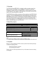
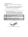
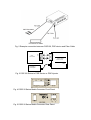
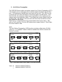
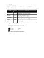
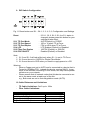
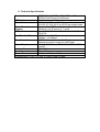
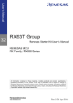
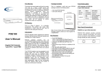
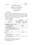
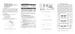
POE120 Series
10/100 Base-TX to 100Base-FX Converter
POE Powered Device
Version 1.01
Date: 13 July 2005
1. Overview
The POE120 Series IEEE 802.3u compliant media converters support two
types of media 10/100 Base-TX and 100Base-FX. With LFP (Link Fault
Propagation) support it allows the administrator to easily diagnose link faults
on their network. If the Copper or Fibre link fails, the converter forces the link
status of the connecting device to also fail.
The POE120 Series media converters are fully compliant to the IEEE 802.3af
standard. The converters advanced auto-sensing algorithm allows the unit to
draw power from any IEEE 802.3af Power Sourcing Equipment (PSE) device
(POE100 Series Converter, or PoE Switch) or Power over Ethernet Injector. It
also supports high levels of safety support with short circuit protection and
power-in auto-detection. The POE120 series converters can be powered from
either a standard plug pack or a PSE device.
2. Model Description
Model
POE120 Series
Power Description
60mA@-48VDC over Cat.5
100Mbps Fibre Transceiver
ST/SC Multimode 2Km
SC.S05/S20/S40/S60Km Single Mode
SC.S80/S100Km Single Mode
Single Fibre Model
1310nm Single Mode 20Km
1550nm Single Mode 20Km
Wavelength
1310nm
1310nm
1550nm
TX, RX Wavelength
TX (Transmit) 1310nm
RX (Receive) 1550nm
TX (Transmit) 1550nm
RX (Receive) 1310nm
Note:
The 1310nm and 1550nm models must be installed in pairs,
i.e., install 1310nm model at one end and the 1550nm model at the other end.
3. Checklist
Before you start installing the POE converter, please verify that the package
contains the following items.
-
The POE120 Series Converter
CD containing this manual
Please notify your sales representative if any of the above items are missing
or damaged.
4. Installing the Converter
4.1 POE120 converter connected to a Power Sourcing Equipment
Device (PSE)
1. Connect the copper cable to your IEEE 802.3af compliant PSE device.
The POE120 can also work as a standard media converter and
connect to a non POE device. (power supply is optional)
2. Connect the fibre cable to your connecting device.
Note:
- Please make sure that the 802.3af power is being supplied from a PSE
device to the PD Media Converter.
- In case there is no 802.3af PSE available or the PSE device power
fails, you may install an AC-DC adapter as a backup solution. Do not
connect the PSE Copper port and a AC-DC adapter at the same time.
(the power options are not designed in a redundant configuration)
Default: Auto
Auto or Force setting, see figure 11. S1-Bit 1
TP
Attach Cat. 5 cable to the copper port and ensure the cable run is not
Port over 100m in distance.
The Copper port supports Auto MDI-X, therefore there is no need to
use a cross-over cable when connecting to a switch.
Fibre Default: 100FDX
Port ”100FDX”/”100HXD” setting, see figure 11. S1-Bit 5
Fig. 1 View of the POE120 Series Media Converter
Fig. 2 Example connection between POE120, PSE device and Fibre Cable
100FX
Fibre Network
RX
TX
TX
RX
POE120 Series
Media Converter
AC
PoE PSE or
PoE Injector
Fig. 3 POE120 Series to PSE Device or POE Injector
POE1 20 Series
10/ 100 Base- TX to 100Base- FX
Fig. 4 POE120 Series Media Converter Front Panel
Fig. 5 POE120 Series Media Converter Rear Panel
Fig. 6 Pairs used for receiving power over Ethernet Cable.
Note:
The pins used for receiving power from a PSE Device follows the
IEEE 802.3af standard.
Endpoint: -48V via TP pins 1, 2, 3, 6
Midspan: - 48V via pins 4, 5, 7, 8
5. WDM Single Fibre Model
The POE120 Series media converter has an optional Wavelength Division
Multiplexing (WDM) Model that can transport bi-directional full duplex signals
over a single fibre simultaneously.
Single Fibre Model
1310nm Single Mode 20Km
1550nm Single Mode 20Km
TX, RX Wavelength
TX (Transmit) 1310nm
RX (Receive) 1550nm
TX (Transmit) 1550nm
RX (Receive) 1310nm
Note:
The 1310nm and 1550nm models must be installed in pairs,
i.e., install 1310nm model at one end and the 1550nm model at the other end.
6. Link Failure Propagation
The POE120 Series media converters support Link Failure Propagation (LFP).
If the Copper port is unplugged, the converter stops transmission on the fibre
port. This causes the remote fibre node link to fail as well. The LED’s on the
converter will now show link failure on both the copper and fibre ports. If the
fibre link fails, the converter restarts auto-negotiation on the copper port but
always stays in the link failure state. This causes the remote copper node link
to fail as well. The LED’s on the converter will now show link failure on both
the copper and fibre ports.
Refer to Fig. 7 shown below for the normal status when link is active. Also
refer to Fig. 8 and Fig. 9 for the LED status when copper Cable A, Fibre Cable
B or Fibre Cable C fails.
Note:
The Link Failure Propagation (LFP) function only takes effect when S1-Bit4
(see Fig. 11) is enabled. When S1-Bit4 is disabled the media converter will
function normally.
10/100
Switch
TP
● ●
●
A
B
LFP
LFP
C
Fibre Cable
10/100
Switch
Remote
Station
TP
● ●
●
Fig. 7 Normal Status via a pair of LFP’s
10/100
10/100
Switch
Switch
A
B
LFP
LFP
TP
TP
C
Fibre Cable
● ○
○
○ ○
○
●
Remote
Station
●
Fig. 8 The Status when Copper Cable A link is broken
10/100
Switch
LFP
TP
○
○ ○
B
C
LFP
A
10/100
Switch
Remote
Station
TP
Fibre Cable
○ ○
○
●
Fig. 9 The Status when Fibre Cable C or B link is broken
Note : ●
○
indicates LNK/ACT LED Lit
indicates LNK/ACT LED Off
7. LED Description
The following table describes the LED’s located on the POE100 Series media
converter.
LED
Colour
FX LNK/ACT
Green
FX
FDX/COL
Amber
TP LNK/ACT
Green
TP 100
Green
PWR
POE
Green
Green
Function
Lit when fibre connection has link
Blinks when fibre data is present
Lit when full-duplex mode is active
Off when half-duplex is active
Blinks when collision is present
Lit when Copper connection has link
Blinks when Copper data is present
Lit when Copper speed is 100Mbps
Off when Copper speed is 10Mbps
Lit when +5V power is supplied
Lit when POE power is supplied
8. DC Jack and AC-DC Power Converter
The DC jacks central post is 2.5mm wide.
DC Jack
DC Input
:
:
2.5mm
+5V
Fig. 10 DC+5V Input Jack and Dimension
9. DIP Switch Configuration
Fig. 11 Reset button and S1 – Bit 1, 2, 3, 4, 5, 6, Configuration and Settings
Reset
S1-1 TP Port Mode
S1-2 TP Port Speed
S1-3 TP Port Duplex
S1-4 LFP
S1-5 Fibre Port Duplex
S1-6 POE ON/OFF
: If S1-1, S1-2, S1-3, S1-4 or S1- status is
changed, please press this button for your
settings to take effect.
: AUTO(Default) or FORCE
: 100 or 10 when TP at Force
: FDX or HDX when TP at Force
: LFP Enabled (Default) or Disabled
: 100FDX (Default) or 100HDX
: Enabled (Default) or Disabled
Note:
1. S1-2 and S1-3 will take effect only when S1-1 is set to TP-Force
2. S1-5 must be set to 100FDX for Single Fibre Model
3. S1-6 must be set to POE when you need to supply power to a PD.
Warning:
- When a Copper port set to AUTO and is connected to a device that is
Forced to 100Mbps FDX , instead of a device running NWAY, it may
result in the devices connecting in HDX mode, this may cause packet
collisions on your network.
- Please ensure that all network nodes that this device connects to are
set to the same mode at each end of the link.
e.g., Both ends are set to Auto-Negotiation mode (AUTO)
10. Cable Distances and Limitations
-
TP Cable Limitations: Cat 5 up to 100m
Fibre Cable Limitations:
SC/ST Converter Models
Multi Mode Half Duplex
412m
Multi Mode Full Duplex
2Km
Single Mode Half Duplex
412m
Single Mode Half Duplex
5/20/40/60/80/100Km
11. Technical Specifications
IEEE 802.3u 10/100Base-TX, 100Base-FX
IEEE 802.3af Power Over Ethernet
Cat. 5 cable up to 100m
UTP Cable:
50/125, 62.5/125 or 100/140 µm multi mode
Fibre Cable:
8.3/125, 8.7/125, 9/125 or 10/125 µm single mode
“Endpoint” Via TP Pins 1, 2, 3 and 6
Power Reception
”Midspan” Via TP pins 4, 5, 7 and 8
Support:
Power, POE, TP LNK/ACT, 100, FX LNK/ACT,
LED Indicators:
FDX/COL
100Mbbps – 148,800pps
Data Transfer Rate:
10Mbps – 14,880pps
IEEE 802.3x compliant for Full Duplex
Flow Control:
Backpressure flow control for Half Duplex
Power Requirements: 60mA@-48VDC from IEEE 802.3af PSE or POE
Injector
Ambient Temperature: 0º to 50º C
5% to 90%
Humidity:
26.2(H) x 70.3(W) x 94(D) mm
Dimensions:
Complies with C-Tick, FCC Part 15 Class A and CE Mark
Standards: