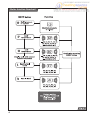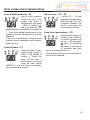
1
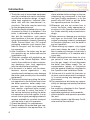
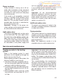
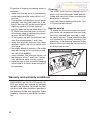
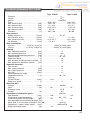
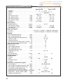
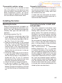
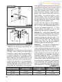
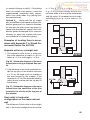
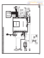
Protherm Tiger 24 (12) KTZ / 24 (12) KOZ
The boiler Serial No. is shown on the plate which is attached at the rear of the control
panel. The control panel is accessible after removing the front cover.
In the “Operating Guide” section you will find a description of the boiler’s main functions
and guidelines how to handle the boiler safely. The “Installation Guide” section is intended
for qualified personnel only.
Table of contents
Introduction ............................................2
OPERATING GUIDE
Controls and signals..............................4
Selecting Read mode ............................5
Selecting Setup mode ...........................5
Error codes and troubleshooting ...........9
Starting the boiler and turning it off .....10
Boiler control .......................................10
Protective functions .............................12
Service and maintenance ...................13
Warranty and warranty conditions .......14
Technical parameters .......................... 15
Boiler working diagram........................ 18
INSTALLATION GUIDE
Introduction ..........................................19
Content of delivery ...............................21
Preparing for installation ......................22
Installing the boiler ...............................23
Air supply and flue gases removal .......27
Electrical wiring ....................................32
Boiler rebuilding for alternative fuel type .32
Boiler electric diagram 24 (12) KOZ .....33
Boiler electric diagram 24 (12) KTZ .....34
1
Tiger
Boiler Operating and
Installation Guide
24 (12) KTZ / v.17
24 (12) KOZ / v.17
Wall-hang combined boiler
Output 9,5 - 23 (3,5 - 11,5) kW
Hot water heat in tank
www.protherm.sk
Protherm spol. s r.o.
Pplk. Pľjušťa 45
909 01 Skalica
Tel.: 034 6966 101
Fax: 043 6966 111
Your service:
EN
version
xxxxxxxxxx_01 - v.1 4/2005
Introduction
1. The boiler and all associated equipment
must be installed and used in accordance with the installation design, all applicable legal regulations, technical standards and with the manufacture’s instructions. The boiler may be used only
for the designed purpose.
2. The boiler may be installed only in an environment for which it is designed. If the
boiler is delivered by the same person
that did the installation, such person
must handover to the user all accompanying documentation (namely Operating
Guide, Service Book, etc.) All original
packaging materials must remain available for transport until the boiler is put
into operation.
3. After installation, the boiler may be put
into operation by an authorised service
organisation only.
4. The boiler complies with regulations applicable in the Slovak Republic. When
used in the conditions of other countries,
any deviations from local regulations
must be identified and rectified.
5. In the event of a defect, call the manufacturer’s service organisation – any
unauthorised interference may damage
the boiler (and possibly also associated
equipment!).
6. The service technician putting the boiler
into operation for the first time must show
the boiler operation, boiler safety components, their function and necessary
user reaction, significant boiler components, and how to control the boiler. If
the service technician putting the boiler
into operation is also the supplier, it must
ensure, that original packaging materials
remains available for possible transport
until the boiler is put into operation
7. Check the delivery for completeness.
8. Check whether the model and type supplied is suitable for the required use, i.e.
2
check whether boiler settings on the manufacturing tag correspond to the local
fuel (gas) supply parameters, or let the
person who will install or put the boiler
into operation perform this check.
9. Whenever you are not certain how to
control the boiler, study appropriate instructions in this Operation and Installation Guide carefully and proceed accordingly.
10.Never remove or damage any markings
and signs on the boiler. Also keep the
original packaging material undamaged
for transport purposes, until the boiler is
put into operation.
11. When making any repairs, only original
parts must always be used. It is forbidden to make any changes to the boiler’s
internal installation, or to interfere with it
in any way.
12.When shutting the boiler down for a longer period of time, we recommend to
turn the gas supply off and disconnect
the boiler from power supply. This recommendation applies in conjunction
with the general conditions stipulated in
this Operation and Installation Guide.
13. At the end of its useful life, the boiler or
its parts must be disposed of ecologically, to avoid causing any damage to the
environment.
14.The manufacturer disclaims any responsibility for damages caused by the failure
to observe:
• the conditions stipulated in this Operation and Installation Guide;
• applicable regulations and standards;
• good installation and operation procedures; and
• conditions stated in the Warranty Certificate and the Service Book.
Situations might occur in practice, when
the following essential measures must be
adopted:
• prevent the boiler from (even accidentally) being turned on while conducting inspections or working on the combustion
gasses flue route or gas and water distribution pipes, by disconnecting the boiler
from power supply also by other means
than merely turning the main switch off
(e.g. by pulling the power cord plug out
of power socket);
• shut the boiler down every time when
there are any (even temporary) flammable or explosive fumes present on the
premises from which combustion air is
supplied to the boiler (e.g. from paint
when painting, laying and spraying molten substances, from gas leaks, etc.);
• if it is necessary to drain water from the
boiler or from the whole system, the water must not be dangerously hot;
• when water is leaking from the boiler’s
heat exchanger or when the exchanger
is clogged up with ice, do not attempt to
start up the boiler until normal operating
conditions have been restored;
• when a gas leak has been detected or
gas supply has been interrupted, or if is
suspected that this has happened, shut
the boiler down, turn the gas supply off
and call the gas supply company or a
service organisation.
Safety of equipment and people
• The boiler (and its additional equipment)
complies with the type verified by the Engineering Testing Institute in Brno, heat
and ecological equipment testing laboratory, as the testing organization and Certified Body No. 1015, which issued its
decision that the boiler has been certified and complies with the requirements
of European Directive 90/396/EEC, 92/
42/EEC, 73/23 EEC and 89/336 EEC,
which set out requirements for gas-fuel-
•
-
-
•
led appliances, efficiency of hot-water
boilers fired by liquefied or gaseous fuels
electrical equipment with low voltage
and electromagnetical compatibility. Furthermore it complies with Slovak technical specifications STN EN 50 165, STN
EN 437, STN EN 483, STN EN 625 and
STN EN 60 335 – 1; it also complies with
STN 06 1008 and Act No. 513/1991 the
Commercial Code, Act No. 634/1992
and Public Notice of the Ministry of Health of CSR No. 13/1997, including all their
later amendments.
In order to run and operate the boiler in
accordance with the purpose for which it
is designed in actual conditions of use
(hereafter referred to only as use), it is
necessary to abide also by additional requirements – the most essential ones of
which (i.e. those which must not be omitted) are found in the following regulatory
documents:
in the design area: STN 06 0310 and
STN 06 0830 (also STN 73 4201 for type
KOZ);
in the fire safety area: STN 92 0300;
for installation and assembly (and repairs): STN EN 1775 or STN 38 6460
(also STN 73 4201 for type KOZ), Public
Notice No. 48/1982 (as amended) and
binding occupational safety regulations;
during running and operation: STN 38
6405.
In addition to the above mentioned documents, it is necessary when using the
boiler to proceed in accordance with this
Operating Guide and the accompanying
boiler manufacturer’s documentation.
Any interference by children, persons
under the influence of narcotic drugs,
certified persons, etc., when using the
boiler, must be prevented.
3
Operating Guide
Controls and signals
Main switch
Main switch
The main switch (Fig. 1) is used to switch
the boiler on or off. The main switch is situated on the bottom side of the boiler in
line with the control panel.
Please note: The boiler must be put into
operation and switched on for the first time
by an authorised service organisation.
Control panel
On the boiler’s control panel you can monitor instantaneous values and set the required parameters.
Description of control elements (Fig.2):
Fig. 1
Control panel
1. Heating water (HeW) LED - indicates
display of pressure.
1
2
3
4
2. Hot water (HoW) LED – indicates display mode or setting of hot water temperature.
3. HeW LED - indicates display mode or
setting of heating water temperature.
4. Error LED - indicates boiler defect.
5. (-) button – used to decrease the value
of the parameter being set.
6
7
9
6. (+) button – used to increase the value
of the parameter being set.
8
7. Display – display of pressures, temperatures, service parameters and errors.
Fig. 2
8. MODE button – switching to different
modes of reading or setting of values,
confirming set values.
9. HoW heating request LED.
4
5
Selecting Read mode
Displaying HeW temperature
After turning the boiler
on with the main switch,
the current heating water
temperature will appear
on the display. LED at
lights up.
symbol
Indicating “HoW temperature”
To display the current
HoW temperature in the
tank, press the
button – the
symbol LED
at symbol lights up. The
flashing dot behind the
number indicates a HoW
heating requirement.
Displaying HeW pressure
Pressing and holding depressed the
button will display HeW pressure (bar) in the system
for about 30 s. The LED at
symbol
lights up.
Warning “HeW pressure too low”
When the HeW pressure
drops below 0.8 bar or
rises above 2.5 bar, the
LED at symbol
flashes.
The boiler is still functional, the pressure must
be adjusted to the recommended value 1 - 2 bar.
Note: For displaying the HeW temperatu.
re again, press
Selecting Setup mode
Setting HoW temperature
Press the
button repeatedly until the
starts
LED at symbol
flashing. Using the
buttons set the HoW temperature to the required
value. Setting range --, 38, 39 40, 41, 42,
45, 50, 55, 60, 65, 70 °C.
Another pressing of the button will save
the parameter. To stop the HoW heating,
save parameter (--).
Setting HeW temperature
Press the
button
repeatedly until the LED
at the symbol
starts
flashing. Using the
buttons set the temperature to the required value.
Setting range --, 38, 40, 42, 45, 50, 55, 60,
65, 70, 75, 80 °C. Another pressing of the
button will save the parameter.
To select the SUMMER mode (heating of
only HoW) select parameter (--).
5
HoW tank timer switch
0
1
s
15
14
r
13
a b
14
13 12 11 1
0
19 18 17 1
6
4
7
8
20
9
15
6
3
21
5
2
1
24 23
22
Fig. 3
Setting time intervals for water tank
heating
The Tiger boiler enables setting of HoW
heating in the tank in various time intervals.
Example: If hot water is not used in the
night, HoW heating may be switched off
(or vice versa) for a given time interval
using the timer switch.
The outer perimeter of the timer switch has
switches which are used to set the switching cycle of tank heating. If the switch
lever is further form the dial (Fig. 3, pos.
a), the tank heating in that time interval is
active and vice versa (Fig. 3, pos. b).
The switch (Fig. 3, pos. s) located above
6
the left side of the dial, is used to select
3 permanent modes. Mode “0” is used for
permanent shutdown of HoW tank heating. Position “1” is used for permanent
HoW tank heating. When the switch is moved to the position of the clock symbol, the
tank heating mode is controlled according
to your setting – position of the individual
timer switches.
Note: Stoppage or activation of HoW tank
heating can be done using the boiler control display (see Setting HoW temperature).
Setting of the timer switch in terms of time
synchronization is done by turning the outer part of the dial to the right until the correct time is set against the arrow.
Equithermal mode – curve
steepness
Equithermal mode – reference
temperature shift
Press the
button
repeatedly until the display shows the letter E
with parameter 0 to 9. Use
to select
buttons
the equithermal curve.
The curve steepness increases with the
set number (E0 < E9), see Fig. 4.
If the previous parameter
“E” was confirmed by the
button, the display will show parameter
“P” with value 0 to 9. Use
to shift the
buttons
reference temperature (see graph in Fig.
4, Table 1).
The corresponding values of the reference temperature – parameter “P” are given
in Table 1. For the initial setting select parameter P5, which corresponds to an outdoor temperature of 15 °C (see graph in
Fig. 4) according to Table 1.
Note: When the boiler reaches the reference temperature it continues to heat the
heating system at a minimum temperature (38 °C), until the outdoor temperature
rises by another 3 °C, then the HeW heating is switched off (see Tab. 1 – switching
off temperature).
Saving to the memory and simultaneous
transfer to parameter “P” is done by pressing the
button.
Note: To activate equithermal control, an
outdoor sensor must be connected and
the boiler must not be in SUMMER mode.
Important: After installing the outdoor
sensor the boiler runs at maximum temperature for 1 hour. All settings are ignored during this period except for the room
control unit (if connected).
Equithermal curves
Fig. 4
Table 1
„P“ parameter
0
1
2
3
4
5
6
7
8
9
Reference temperature °C
6
7
9
11
13
15
17
19
21
23
Switching off temperature
9
10
12
14
16
18
20
22
24
26
7
Boiler function flowchart
Fig. 5
8
Error codes and troubleshooting
Loss of HeW pressure - F0
Loss of HeW pressure
(under 0.6 bar) in the
system. The boiler is
automatically shut down
– LEDs at symbols
and are flashing. Add
heating water to the system to pressure at
1 - 2 bar. After adding heating water to the
system the boiler automatically resumes
operation.
If the loss or exceeding of heating water
pressure occurs repeatedly, call an authorized service.
Loss of flame – F1
Flame loss due to interruption of gas supply to
boiler – LED flashes at
symbol
. Switch the
boiler off and after a
while switch it back on
using the main switch
(RESET). If the error occurs repeatedly
call an authorized service.
Other errors – F2 – F8
If errors F2 – F8 are
displayed call an authorized service. The LED
at symbol flashes. The
boiler is shut down, call
an authorized service.
Loss of set parameters – F9
Under certain boiler parameters the customer
or service settings may
be lost – LED at symbol
lights up. Switching
the boiler off (wait about
10 seconds) and back
on should remedy this error.
After remedying the error the set parameters must be checked.
9
Starting the boiler up and turning it off
Starting the boiler up
Important: Putting the boiler into operation and starting it up for the first time must
be done by an authorised service only!
If you wish to start the boiler after it has
been put into operation, make sure that:
1. the boiler is connected to power supply;
2. the gas valve underneath the boiler is
open;
3. the HeW pressure is within the recommended range 1 – 2 bar.
Turn the main switch (Fig. 1) to position (I).
The display will light up.
In the event of a safety boiler shutdown
during a flame-out, emergency thermostat
or flue gas thermostat (applies to KOZ boiler) intervention, the “lightning” LED on the
control panel will flash or light up. In case
of a flame-out the boiler can be unblocked
using the main switch by switching it to position (0) and after a while back to position
(I). If the emergency shutdown recurs after a short time again, or if the boiler cannot be RESET, call an authorised service
organisation.
If the emergency shutdown was triggered
by the emergency thermostat intervention, the boiler cannot be unblocked by
the main switch (RESET). Unblocking the
emergency thermostat must be done by
an authorised service technician, and this
operation cannot be regarded as a warranty repair.
Important: The boiler must not be run
with the emergency or flue gas thermostat
disabled or replaced with a device other
than the one specified by the manufacturer.
Turning the boiler off
Turn the main switch (Fig. 1) to position
(0).
If the boiler is to remain shut down for a
protracted period of time, turn off the gas
valve upstream the boiler. When shutting
the boiler down, take into consideration
the ambient temperature in the given season. If the boiler and system is not protected by an anti-freeze agent (Alycol Termo),
the boiler and system may be damaged. If
there is a danger that the boiler may freeze, drain all the HoW pipes.
Boiler control
Using the boiler without room
control unit
When run in this mode, the boiler maintains the set HeW temperature. No room
control unit is connected, the terminals
for its connection must be interconnected
with a jumper (standard factory setting).
Setting procedure:
• turn the main switch to position (I);
• set the HeW temperature to the required
value on the control panel.
10
Using the boiler with room control
unit
The boiler maintains the set HeW temperature. The room control unit connection
terminal jumper must be removed and the
room control unit wired to the terminals.
The boiler is turned on and off to maintain
the set temperature in the room in which
the control unit is installed. Radiators in
this room must not be equipped with thermostatic valves.
Important: You must set on the boiler
control panel a HeW temperature (tempe-
rature of the water in the system) which
will be capable of covering thermal losses
of the building even in low outdoor temperatures. We recommend selecting a temperature in the 60 – 80 °C range.
Using the boiler with equithermal
control
The boiler changes the HeW temperature
as the outdoor temperature changes.
Please note: An outdoor temperature
sensor must be connected! The outdoor
sensor is to be located on the building’s
coldest wall (north or north-west) about
2.5 – 3 m above the ground. No false heat
sources from open windows or ventilation
shafts, or sunshine may affect the sensor.
When selecting a heating curve it applies
that curves with a lower number are suitable for buildings with good thermal insulation and a higher thermal gradient and
vice versa.
The heating curves diagram is used as initial information. More precise setting must
be done by monitoring outdoor and indoor
temperature over several days.
Select E5 for the initial system setting.
During setting all the radiator valves must
be open, thermostatic valves must be set
to maximum temperature, doors and windows must be closed.
Setting the curve steepness or reference
temperature shift is done in small increments and prior to evaluating the change made a period of about. 2 hours must
elapse. For setting purposes a greater fluctuation of outdoor temperature is better,
and the final setting is done when the outdoor temperature drops below 0 °C.
Setting procedure:
1. Select “HeW temperature” mode and
check that the SUMMER function is not
on (symbol --).
A certain temperature must be set (the
temperature value does not affect the
equithermal mode).
2. Select “equithermal mode – curve steepness” and set symbol E5 – see pg. 7.
3. Select “equithermal mode – reference
temperature shift” and set symbol (P5).
4. Set the boiler to the initial status.
After several days of operation (when the
building is heated) make changes to the
curve steepness, as necessary:
5. If the room temperature does not change substantially in reaction to changes of
outdoor temperature, the curve selection
is correct. The temperature can be set to
a higher or lower value by shifting the reference temperature – see “Controls and
signals – equithermal mode – reference
temperature shift”.
Note: If the room temperature changes
substantially in reaction to changes of outdoor temperature, i.e. the indoor temperature rises when the outdoor temperature
drops, select a heating curve with a lower
number, and vice versa.
Operation with equithermal control
and a room control unit
Equithermal control is supplemented with
the room control unit by time control and
reduction (e.g. night) of heating.
Setting procedure:
• set the equithermal control according to
the preceding point;
• Connect the room control unit to the boiler (remove the jumper from the connection terminal) and set it so that during the
comfortable temperature period the required temperature is set about 5 °C higher
than is achieved by equithermal control.
During the heating reduction period (during the night or absence) the actually
required temperature is set on the control
unit – must always be at least ca. 3 °C
lower than the actual comfortable temperature.
Important: The room control unit must be
installed by an authorized service.
11
Example: Select curve E5. At an outdoor
temperature of -10 °C the boiler provides
the heating system with a temperature of
70 °C. If the reference temperature shift
parameter P5 is selected at the same
time, then at an outdoor temperature of
15 °C the boiler will supply a temperature
of 38 °C. When the outdoor temperature
rises above 18 °C the HeW heating is switched off.
Setting boiler output
The factory setting of the boiler output is
15 kW to the heating system. During heating the HeW the boiler uses its maximum
nominal output of 24 (12) kW.
Important: Changes in the boiler output
settings must be performed only by an authorized service.
Protective functions
Protection against freezing
The boiler has an antifreeze protection
system which protects the boiler (but not
the heating and the hot water distribution
systems) against freezing.
When the HeW temperature in the boiler
drops below 4 ˚C, the boiler is automatically switched on regardless of the room
control unit’s command, or regardless of
the HeW heating being switched off – parameter (--). When the HeW temperature
reaches 8 ˚C, the boiler is automatically
turned off.
Disconnecting the boiler from power
supply
If the boiler is disconnected from power
supply for a protracted period of time
(continuously for a month or longer), we
recommend to start up the boiler in regular time intervals (at least once a month). If
the pump ceases, call an authorised service. Repairing a pump ceased because
of dirt in the heating system is not covered
by the boiler warranty.
Important: When the boiler is disconnected from the power supply, all protective
functions are disabled.
Pump protection
When the pump has been continuously
idle for 24 hours, it is automatically switched on for about 30 seconds, to prevent
it from ceasing.
Anti-cycling
A function which prevents the boiler from
restarting the HeW heating cycle after the
boiler has been turned off sooner than the
time determined by the control board by
evaluating the required and actual HeW
temperature. This time is within the range
of 1 min 30 s and 5 minutes. The function
is most useful in heating systems where
the maximum thermal loss of the premises corresponds to the lowest level of the
boiler’s output range.
12
Power failure
Power failure will turn the boiler off. When
power supply is restored, the boiler will
automatically restart itself without losing
any of the set operating parameters.
If after power supply restoration the LED
on the control panel (lightning symbol)
lights up, proceed in accordance with the
instructions in section Control and signals
/ Main switch.
The boiler may get blocked because of
overheating caused by the pump being
switched off as a result of the power failure.
Pump run-down
Pump run-down is factory set to 45 seconds after termination of the command
from the room control unit. If the boiler is
run without a room control unit, the pump
runs continuously.
If this mode is not acceptable, a second
setting is available which enables pump
run-down after 45 seconds from burner
flame out. This run-down mode is recommended when the boiler is controlled without a room control unit.
Important: Changes in the pump run-down settings must be performed only by
an authorized service technician.
HeW safety valve
The boiler is equipped with a safety valve
on the HeW side. The valve opens when
the pressure in the heating system reaches 3 bar. DO NOT TOUCH THE SAFETY VALVE! If the safety valve starts releasing heating water, always turn the boiler
off, disconnect it from power supply and
call an authorised service organisation.
If the heating system repeatedly looses
pressure, consult your service organisation.
Important: All the above-mentioned
electronic protection functions are enabled only when the boiler is connected to
power supply (the power cord plug is inserted into a power socket and the main
switch is in position (I)).
HoW tank safety valve
To prevent over pressure of water in the
tank due to heating, the boiler is fitted with
a safety valve (6 bar).
Tank protection
The inside of the tank is protected against
oxygen corrosion by a magnesium anode
that must be checked at least once a year.
The anode ruction depends also on the
water composition.
Note: The magnesium anode is to be
checked only by an authorized service.
Service and maintenance
Topping up water in the heating
system
Water in the heating system (in small
quantities) can be topped up through the
boiler’s top-up valve (Fig. 6).
When topping up water in the system, the
following conditions must be met:
1. Pressure of the water supplied to the boiler must always be higher than the water
pressure inside the heating system.
2. The boiler must be cold when being topped up (HeW temperature must not exceed 30 ˚C).
3. Recommended water pressure inside
the cold boiler (not more than 30 ˚C) is 1
to 2 bar.
Important: If the water mains pressure is
lower or equal to the water pressure inside the heating system, the heating water
may run into the water mains, which is forbidden. This danger is reduced by a built-in reverse valve installed downstream the
top-up valve.
This notwithstanding, the manufacturer
disclaims responsibility for any damages
caused by incorrect manipulation with the
top-up valve and a failure to abide by the
conditions specified above. Such damages and defects are not covered by the
boiler’s warranty.
13
Procedure of topping up heating water in
the boiler:
• make sure that the boiler is connected to
power supply and the main switch is in “I”
position;
• if the display on the boiler’s control panel
indicates that the HeW pressure is below 0.5 bar, the LED on the control panel
(lightning symbol) will start flashing;
• partially open the top-up valve (blue, Fig.
6). Watch the pressure grow on the boiler’s display panel (to display the pressure press the MODE button);
• fill the system up until the pressure reaches the value between 1 and 2 bar;
• when the required pressure has been
reached, tighten the top-up valves with
your hand;
• thoroughly bleed all radiators (the water
must be running out in a continuous stream, free of air bubbles);
• check whether the pressure shown on
the display is within 1 and 2 bar. If necessary, add more water into the system.
• leave the cap on the automatic bleeding
valve loose at all times (even during boiler operation)
Cleaning
The boiler cover can be cleaned with a
moist cloth and afterwards dried and polished with a dry cloth. Never use abrasive
detergents or solvents.
Important: before cleaning the boiler, turn
it off with the main switch.
Regular service
To assure trouble-free and safe running of
your boiler, we recommend that you have
the boiler checked and serviced in regular yearly intervals. These inspections are
not covered by the boiler’s warranty. The
operations to be done are specified in the
Service Book and must be carried out by
an authorised service.
Water top-up system
Fig. 6
Warranty and warranty conditions
PROTHERM Tiger 24 (12) KTZ and 24 (12)
KOZ gas boilers are covered by warranty
defined in the Warranty Certificate, the Service Book and other conditions specified in
the Operation Guide and Installation Guide
(chapters Introduction and Boiler installation).
14
Technical parameters 24 (12) KOZ
Tiger 24 KOZ
Tiger 12 KOZ
Category . . . . . . . . . . . . . . . . . . . . . . . . . . . . . . . . . . . . . . . . . . . . . . . II2H3P
Version . . . . . . . . . . . . . . . . . . . . . . . . . . . . . . . . . . . . . . . . . . . . . . . . B11BS
Ignition . . . . . . . . . . . . . . . . . . . . . . . . . . . . . . . . . . . . . . . . . . . . . . electronic
Fuel . . . . . . . . . . . . . . . . . . . . . . . . . . . . . . . . . . . . . . G20 / G31 . . . . . . . . . . . .G20 / G31
Max. thermal input . . . . . . . . . . . . . . . . [kW] . . . . . . 25,5 / 25 . . . . . . . . . . . . 12,5 / 11,4
Min. thermal input . . . . . . . . . . . . . . . . . [kW] . . . . . . 11 / 10,5 . . . . . . . . . . . . . 4,3 / 4,7
Max. thermal output . . . . . . . . . . . . . . . [kW] . . . . . . 23,5 / 22,5 . . . . . . . . . . . .11,25 / 10
Min. thermal output . . . . . . . . . . . . . . . . [kW] . . . . . . . 9,5 / 9 . . . . . . . . . . . . . . 3,5 / 3,8
Efficiency. . . . . . . . . . . . . . . . . . . . . . . . . [%] . . . . . . 90,7 / 90 . . . . . . . . . . . . . . 90 / 88
Gas pressure
Supply pressure . . . . . . . . . . . . . . . . .[mbar] . . . . . . . . . . . . . . . . . . 20 / 37
Min. pressure at jets . . . . . . . . . . . . . .[mbar] . . . . . . . 2,2 / 7 . . . . . . . . . . . . . . 1,7 / 6,5
Max. pressure at jets . . . . . . . . . . . . . .[mbar] . . . . . . 12,2 / 35,7 . . . . . . . . . . . 14,0 / 35,6
Jet diameter . . . . . . . . . . . . . . . . . . . . .[mm] . . . . . . . 1,2 / 0,7 . . . . . . . . . . . . . 1,2 / 0,73
Gas consumption
(Q max.) . . . . . . . . . . . . 2,7[m3/h] / 2,1[m3/h] . . . . . . . . . . . . 1,32[m3/h] / 0,92 [kg/h]
(Q min.) . . . . . . . . . . . 1,1 [m3/h] / 0,9 [m3/h] . . . . . . . . . . . . 0,45[m3/h] / 0,38 [kg/h]
Heating
Max. operating pressure . . . . . . . . . . . . [bar] . . . . . . . . . . . . . . . . . . . . . 3
Min. operating pressure . . . . . . . . . . . . [bar] . . . . . . . . . . . . . . . . . . . . 0,8
Recommended operating pressure. . . . [bar] . . . . . . . . . . . . . . . . . . 1,2 – 2
Thermal range. . . . . . . . . . . . . . . . . . . . .[°C] . . . . . . . . . . . . . . . . . . 45 – 85
Expansion vessel . . . . . . . . . . . . . . . . . . . [l] . . . . . . . . . . . . . . . . . . . . . 8
Max. quantity of heating water in system . [l] . . . . . . . . . . . . . . . . . . . . 70
Max. pressure in expansion vessel . . . . [bar] . . . . . . . . . . . . . . . . . . . . . 3
Domestic hot water
Tank volume . . . . . . . . . . . . . . . . . . . . . . . [l] . . . . . . . . . . . . . . . . . . . . 45
Max. supply pressure . . . . . . . . . . . . . . [bar] . . . . . . . . . . . . . . . . . . . . . 6
Min. supply pressure . . . . . . . . . . . . . . . [bar] . . . . . . . . . . . . . . . . . . . . . 1
Min. flow . . . . . . . . . . . . . . . . . . . . . . . [l/min] . . . . . . . . . . . . . . . . . . . . 2,7
Adjustable thermal range
(depending on flow) . . . . . . . . . . . . . . . .[°C] . . . . . . . . . . . . . . . . . . 38 – 70
HoW tap
(Di per EN 625) . . . . . . . . . . . . . . . . . . [l/min] . . . . . . . 12,6. . . . . . . . . . . . . . . . . . 8
Expansion vessel . . . . . . . . . . . . . . . . . . . [l] . . . . . . . . . . . . . . . . . . . . . 2
Electrical data
Voltage . . . . . . . . . . . . . . . . . . . . . . . . [V/Hz] . . . . . . . . . . . . . . . . . . 230/50
Input . . . . . . . . . . . . . . . . . . . . . . . . . . . . [W] . . . . . . . . . 95 . . . . . . . . . . . . . . . . . .70
Protection cover . . . . . . . . . . . . . . . . . . . . . . . . . . . . . . . . . . . . . . . . . IP 45
Current . . . . . . . . . . . . . . . . . . . . . . . . . . [A] . . . . . . . . . . . . . . . . . . . . 0,5
Extraction of combustion gases . . . . . . . . . . . . . . . . . . . . . . . . . . . chimney
Flue diameter . . . . . . . . . . . . . . . . . . . .[mm] . . . . . . . . 130 . . . . . . . . . . . . . . . . . 110
Combustion gases temperature . . . . . . .[°C] . . . . . . . . . . . . . . . . . . 95 – 120
Combustion gases flow by weight . . . . . [g/s] . . . . . . . . . 20. . . . . . . . . . . . . . . . . . .16
Min. required constant chimney draught [Pa] . . . . . . . . . . . . . . . . . . . . . 2
Noise level (1 m from boiler at height 1,5 m) [dB] . . . . . . . . . . . . . . . up to 55
Dimensions – height / width / depth . . .[mm] . . . . . . . . . . . . . . . . 900/410/570
Weight excluding water . . . . . . . . . . . . . . [kg] . . . . . . . . . 70. . . . . . . . . . . . . . . . . . .69
15
Technical parameters 24 (12) KTZ
Tiger 24 KTZ
Tiger 12 KTZ
Category . . . . . . . . . . . . . . . . . . . . . . . . . . . . . . . . . . . . . . . . . . . . . . II2H3P
Version . . . . . . . . . . . . . . . . . . . . . . . . . . . . . . . . . . . . . . . C12, C32, C42, C52, C62, C82
Ignition . . . . . . . . . . . . . . . . . . . . . . . . . . . . . . . . . . . . . . . . . . . . . . electronic
Palivo . . . . . . . . . . . . . . . . . . . . . . . . . . . . . . . . . . . . G20 / G31 . . . . . . . . . . G20 / G31
Max. thermal input . . . . . . . . . . . . . . . . [kW] . . . . . . . 26 / 25 . . . . . . . . . . . . 12,3 / 11,2
Min. thermal input . . . . . . . . . . . . . . . . . [kW] . . . . . . 11 / 10,5 . . . . . . . . . . . . 4,2 / 4,4
Max. thermal output . . . . . . . . . . . . . . . [kW] . . . . . . 24 / 22,5 . . . . . . . . . . . .11,2 / 10
Min. thermal output . . . . . . . . . . . . . . . . [kW] . . . . . . . 9,5 / 9 . . . . . . . . . . . . . 3,5 / 3,6
Efficiency. . . . . . . . . . . . . . . . . . . . . . . . . [%] . . . . . . 91,7 / 90,5 . . . . . . . . . . .91 / 89,9
Gas pressure
Supply pressure . . . . . . . . . . . . . . . . . [mbar] . . . . . . . . . . . . . . . . . 20 / 37
Min. pressure at jets . . . . . . . . . . . . . . [mbar] . . . . . . . 2,2 / 7 . . . . . . . . . . . . . 1,6 / 5,8
Max. pressure at jets . . . . . . . . . . . . . . [mbar] . . . . . . 12,2 / 35,7 . . . . . . . . . . .14 / 35,8
Jet diameter . . . . . . . . . . . . . . . . . . . . . [mm] . . . . . . . 1,2 / 0,7 . . . . . . . . . . . 1,2 / 0,73
Gas consumption
(Q max.) . . . . . . . . . . . . . . . . . . . . . . . . . . . . . . 2,7 [m3/h] / 2,1 [kg/h] . 1,30[m3/h] / 0,93 [kg/h]
(Q min.) . . . . . . . . . . . . . . . . . . . . . . . . . . . . . . . 1,1[m3/h] / 0,9 [kg/h]. . 0,44[m3/h] / 0,37 [kg/h]
Heating
Max. operating pressure . . . . . . . . . . . . [bar] . . . . . . . . . . . . . . . . . . . .3
Min. operating pressure . . . . . . . . . . . . [bar] . . . . . . . . . . . . . . . . . . . 0,8
Recommended operating pressure. . . . [bar] . . . . . . . . . . . . . . . . . 1,2 – 2
Thermal range. . . . . . . . . . . . . . . . . . . . . [°C] . . . . . . . . . . . . . . . . . 45 – 85
Expansion vessel . . . . . . . . . . . . . . . . . . . [l] . . . . . . . . . . . . . . . . . . . .8
Max. quantity of heating water in system . [l] . . . . . . . . . . . . . . . . . . . 70
Max. pressure in expansion vessel . . . . [bar] . . . . . . . . . . . . . . . . . . . .3
Domestic hot water
Tank volume . . . . . . . . . . . . . . . . . . . . . . . [l] . . . . . . . . . . . . . . . . . . . 45
Max. supply pressure . . . . . . . . . . . . . . [bar] . . . . . . . . . . . . . . . . . . . .6
Min. supply pressure . . . . . . . . . . . . . . . [bar] . . . . . . . . . . . . . . . . . . . .1
Adjustable thermal range
(depending on flow) . . . . . . . . . . . . . . . . [°C] . . . . . . . . . . . . . . . . . 38 – 70
HoW tap
(Di per EN 625) . . . . . . . . . . . . . . . . . . [l/min] . . . . . . . 12,6 . . . . . . . . . . . . . . . . .8
Expansion vessel . . . . . . . . . . . . . . . . . . . [l] . . . . . . . . . . . . . . . . . . 2
Electrical data
Voltage . . . . . . . . . . . . . . . . . . . . . . . . [V/Hz] . . . . . . . . . . . . . . . . . 230/50
Input . . . . . . . . . . . . . . . . . . . . . . . . . . . . [W] . . . . . . . . 120 . . . . . . . . . . . . . . . . 95
Protection cover . . . . . . . . . . . . . . . . . . . . . . . . . . . . . . . . . . . . . . . IP X4D
Current . . . . . . . . . . . . . . . . . . . . . . . . . . .[A] . . . . . . . . . . . . . . . . . . . 0,6
Extraction of combustion gases . . . . . . . . . . . . . . . . . . . . . . . . . . . turbo
Flue diameter . . . . . . . . . . . . . . . . . . . . [mm] . . . . . . . . . . . . . 100 / 60 (80 / 80)
Max. length of concentric flue 60 / 100 . [Em] . . . . . . . . . . . . . . . . . . . .7
Max. length of separate flue 80 + 80 . . . [Em] . . . . . . . . . . . . . . . . . . . 14
Combustion gases temperature . . . . . . . [°C] . . . . . . . . . . . . . . . . 115 – 145
Combustion gases flow by weight . . . . . [g/s] . . . . . . . . . 18. . . . . . . . . . . . . . . . . 15
Noise level (1 m from boiler at height 1,5 m) [dB] . . . . . . . . . . . . . . . do 55
Dimensions – height / width / depth . . . [mm] . . . . . . . . . . . . . . 900 / 410 / 570
Weight excluding water . . . . . . . . . . . . . . [kg] . . . . . . . . . 71. . . . . . . . . . . . . . . . . 70
16
Boiler connection dimensions
1. HeW outlet G3/4“
2. HoW outlet G1/2“
3. Gas inlet G1/2“
4. HoW inlet G1/2“
5. HeW inlet G3/4“
6. Tank drain
Fig. 7
Připojovací
rozměry
kotle
Usable gauge
pressure
to the system
Fig. 8
17
Function schematic diagram
KOZ
KTZ
1
2
3
4
28
27
5
26
25
24
23
22
6
21
20
19
18
17
7
16
10
15 14
1*. Combustion gas thermostat
13
12
9
8
11
9. HoW draining valve
19. Bypass
1. Air manostat
10. HeW safety valve
20. 3-way motor valve
2*. Draught valve
11. HeW inlet
21. Draining valve
2. Fan
12. HoW inlet
22. Pressure sensor
3. HoW tank insulation
13. Gas inlet
23. Pump
4. HoW tank
14. HoW outlet
24. Gas valve
5. HoW heat exchanger
15. HeW outlet
25. Burner
6. HoW expansion vessel
16. HeW top-up valve
26. HeW temperature sensor
7. HeW expansion vessel
17. HoW flow meter
27. Emergency thermostat
8. Anode
18. HoW safety valve
28. HeW heat exchanger
Fig. 9
18
Installation Guide
Introduction
The boiler must be put into operation and warranty and post-warranty service performed by
the manufacturer’s contracted service organisation which meets the above specified requirements.
The boiler is designed to work in an normal
AA5/AB5 environment according to STN 33
2000-3 and STN 33 2000-5-51 (i.e. within temperature range +5 to +40 °C, humidity depending on temperature, not exceeding 85%).
The 24 (12) KTZ a 24 (12) KOZ boilers are
suitable for the conditions of zones 2 and 3
(Fig.10), in rooms with a bath tub or shower and
washing rooms according to STN 33 2000-7701; they may not be installed in zone 0. When
installed in one of the above rooms, the boiler
must have a protection against electric shock in
accordance with the same standard.
The boiler may be (according to Ministry of Health Notice No. 13/1977, i.e. by their noise level)
installed in residential and communal rooms.
The boilers are designed to run with heating
water compliant with STN 07 7401 (which under no circumstances can be acidic, i.e. its pH
factor must be greater than 7 and must have a
minimal carbonate hardness).
Requirements on utility water properties are
defined by STN 83 0616 (on drinking water by
STN 75 7111). If the water has a sum of cal-
Problems caused by clogging of the system
with dirt from the heating system or incrustation
sediments or clogging-induced problems (e.g.
clogging of the heat exchanger, pump defects)
are not cover by the boiler’s warranty.
Zones
Zóna 3
Zóna 1
Zóna 2
Important: PROTHERM boilers must be put
into operation by an authorised organisation
only, according to Czech Bureau of Occupational Safety and Czech Safety Inspectorate Notice No. 21/1979 (in the wording of Public Notice
No. 554/1990).
cium and magnesium concentration greater
than 1.8 mmol/l, it is useful to implement other
“non-chemical” measures against incrustation
(e.g. magnetic water treatment combined with
a desludging device).
Zóna 2
The PROTHERM Tiger 24 (12) KTZ a 24 (12)
KOZ boilers are compatible with common types of HoW heating systems and heating radiators.
Zóna 3
0,6 m
0,6 m
na
Zó
0
0,6
m
Fig. 10
Distance from flammable materials (e.g.
PVC, chipboard, polyurethane, synthetic
fibres, rubber and other) must be sufficient so that the surface temperature of these materials does not exceed 80 °C. The
safe distance for reaching this highest
temperature must be observed regardless
of the flammability grade of a specific material according to STN 73 0823. No flammable materials may be placed on the boiler (permanently or temporarily) or in this
safe distance.
Important: Surface temperature of the
boiler upper parts (particularly the side
walls and the cover) of a working boiler
might exceed the ambient temperature by
up to 50 °C.
19
The manipulation (free) space left around
the boiler must be sufficient for a person
to work on it safely with bare hands and
with common hand tools. Recommended
distances are min. 300 mm from each side
and min 600 mm in front of the boiler).
ding to the boiler throat. It is forbidden to
place into the flue duct an objects obstructing the flow of combustion gasses (e.g.
various heat exchangers for utilization of
residual heat). The flue duct is not part of
the boiler delivery.
Boilers are delivered independently, their
accessories are delivered separately (see
next section “Content of delivery”). Boilers
must be installed with the essential accessories (e.g. combustion gas flues, air supply ducts) to ensure their functionality and
proper operation.
The flue duct and chimney must be constructed in accordance with STN 06 1610
and STN 73 4201. By complying with principles set out in respective standards you
will prevent undesirable effects like excessive combustion gas cooling, penetration
of moisture into walls, variable chimney
draught, including undesirable influence
on boiler operation. The boiler consumes
combustion air from the area in which it is
located. This area must comply with all requirements on combustion air. The supply
and sufficient quantity of combustion air
must be solved in compliance with valid
regulations.
In the case of 24 (12) KTZ combustion
gases must be removed and fresh air supplied through a special for this purpose
designed dual tubing. Practically any required dual-tube route can be constructed
from standard components supplied by
the manufacturer. The flue route must be
constructed in such a way that condensed
water vapour contained in the combustion
gases can be removed from the tubing.
This is achieved by using special components which can be built into the flue
route. Problems caused by condensate
penetration are not covered by the boiler’s
warranty. Due to the considerable variety
of particular solutions, the dual tubing is
not part of the boiler delivery and is not
included in the price. Principles for route
design and construction are described in
chapter Air supply and flue gases removal.
Type 24 (12) KOZ is designed for flue removal via a chimney (through a chimney
duct) with a minimal constant draught of 2
Pa. The boiler is connected to the chimney
using a flue duct of dimensions correspon-
20
Content of delivery
Boiler delivery
PROTHERM Tiger 24 (12) KTZ and 24
(12) KOZ boilers are delivered completely
assembled and functionally tested.
Content of delivery
The delivery contains (Fig. 11):
6
1. Boiler
2. Operations and Installation Guide
3. Service Book
Záručný list
4. List of Service Centres
Seznam servisných
stredisiek
5. Warranty Certificate
Servisná kniha
6. Mounting bar including fixing material
Návod k obsluhe
a instalácii
5
2
Special delivery
Based on requirements the following accessories can be ordered:
3
4
1
1. Flue components ø 60/100 for model
KTZ, e.g.:
– S5D-1000 Horizontal set (elbow with
flange 90°, 1 m termination), ord. No.
7194
– K1D Elbow 90°, ord. No. 2842
– T1D-1000 Extension, ord. No. 2825
Fig. 11
– S3 Chimney set (roof termination),
ord. No. 2805
– Z1 Condensate trap, ord. No. 2857
2. Flue components ø 80 for model KTZ,
e.g.:
– S2 Separate set (distributor, 2 × elbow
90°, 2 × pipe 1 m termination), ord. No.
2803
– K2A Elbow 90°, ord. No. 2830
– T2 Separate pipe (1 m extension), ord.
No. 2819
– S4 Chimney set (roof termination), ord.
No. 2809
– Z2 Condensate trap, ord. No. 2858
21
Preparing for installation
Distribution pipes
Nominal pipe inside diameter is chosen in
the usual way based on the pump characteristic. Distribution pipes are designed
according to the requirements on system
performance, not according to the boiler’s
maximum output. The system must allow
sufficient flow so that the temperature difference between the supply and the return
pipe is smaller than or equal to 20 °C. Minimum flow must be 500 l/h.
The piping system must be constructed
to prevent air bubbles from developing,
making permanent bleeding of the system
easier. Vents should be situated on all high
points of the system and on all radiators.
It is recommended to install a system of
heating water, domestic hot water and gas
shutting valves.
We recommend that you install on the
lowest point of the heating system a drainage valve which will also dub as a heating system top-up valve.
Important: If the boiler is connected to a
floor heating system, a fitting must be installed downstream of the boiler outlet to
prevent heating water of an unacceptable
temperature from entering the system.
The setting of the safety fitting depends
on the properties of the used piping.
Before final installation of the boiler, the
heating distribution system pipes must be
flushed a few times with pressurised water. In old, already used systems, the flushing must be done in opposite direction
to the heating water flow.
Important: Prior to connecting the boiler
to the heating system remove all plastic
plugs from outlet necks.
Heating system cleanliness
Before installing a new boiler, it is es22
sential to clean the system thoroughly. In
old systems it is necessary to remove all
sludge settled at the bottom of the heating
radiators (particularly in gravity systems).
In new systems it is necessary to remove
all conservation material which the majority of radiator manufacturers use.
It is recommended to install upstream
the boiler (i.e. to the HeW return pipe) a
sludge trap. The sludge trap should be designed in such a way that it is easy to empty in regular time intervals without having
to drain a lot of water from the heating
system. The trap can be combined with a
filter, but a filter with a sieve on its own will
not provide sufficient protection. The filter
and the sludge trap must be checked and
cleaned regularly.
HeW circulation in the system
Although the boiler is equipped with a bypass, we recommend to design the heating system so that the heating water can
flow through at least some of the radiators
all the time.
Using antifreeze
We do not recommend to use antifreeze,
because of their unsuitable properties for
the boiler. It is mainly their reduced heat
transfer, large volume expansion, aging
and damage of rubber parts.
In necessary cases it is permitted to use
antifreeze Alicol Termo (produced by
Slovnaft Bratislava) – according to the
producer’s experience use of this antifreeze cannot lead to reduced safety and
influence on boiler operation. If even this
method of preventing heating system freezing cannot be used, non-performance
by the boiler and potential boiler damage
due to use of other antifreeze agents cannot be covered by the warranty.
Thermostatic radiator valves
If a room control unit is installed, at least
one of the radiators in the reference room
must be without a thermostatic valve. For
better temperature comfort, we recommend to leave all radiators in the reference room without a thermostatic valve.
Domestic HoW system
The HoW pressure must be 1 to 6 bars. If
the pressure exceeds 6 bars, a reduction
valve combined with a safety valve must
be installed at the inlet.
In areas with very hard water we recommend to implement suitable measures to
reduce the water hardness.
Installing the boiler
Mounting the boiler
When mounting the boiler, proceed in accordance with design documentation conditions (e.g. wall load-bearing properties,
chimney inlet, pipe inlet and outlet connections).
Mounting procedure (Fig. 12):
1. To fix the boiler mounting bar (part of the
boiler delivery) on the supporting wall
mark a line along the top edge of the boiler (Fig. 12, pos. 4). Use a level.
2. Place the mounting bar on the marked
line (Fig. 12, pos. 3) and mark the holes
in the bar onto the wall. Then drill the
marked holes to the required diameter.
Insert the brackets into the drilled holes,
position the bar and secure it using appropriate screws.
3. If the boiler model with forced combustion gas extraction (KTZ) is being mounted, and the flue duct is terminated in a
façade wall (Fig. 12, pos. 2), measure
the opening for the concentric duct (see
the boiler connection dimensions).
4. Mount the boiler on the mounting bar.
5. In the case of model KTZ, install a combustion gas extraction pipe. The space
between the pipe and opening in the wall
is to be filled using non-flammable material.
Connecting the boiler to HeW, HoW
and gas pipes
The boiler connection end pieces must
not be subjected to any forces from the
heating water, domestic hot water or gas
piping system. This requires accurate positioning of all connection pipes, vertically
(height) as well as the distance from the
wall and mutual distance between inlets
and outlets.
We recommend to design the heating system in such a way that when making repairs, it will be possibly to drain the whole
heating system from the boiler.
After reconstructions, in unfavourable
building dispositions, etc., it is possible
to connect the boiler to the heating system, the domestic HoW system as well as
the gas supply by flexible hoses, but only
those designed for that purpose. Flexible
components should be as short as possible, must be protected against mechanical and chemical loads and damage, and
must be replaced with new ones before
the end of their useful life cycle or reliability to meet their nominal specifications (as
stated by their manufacturers).
23
Mounting the boiler
4
3
1
2
Fig. 12
Operating pressure in the heating
system
The heating system (measured on the
boiler) must be filled at least to the hydraulic pressure of 1 bar (corresponds to
a 10 m hydrostatic water column). We recommend that you maintain the pressure
within the range 1 – 2 bar. The expansion
vessel capacity is sufficient for up to 70 l
of heating water in the heating system (at
temperature 85 °C).
HeW expansion vessel
Before filling the heating system up, check
pressure in the expansion vessel. The initial pressure inside the expansion vessel
should be 0.2 – 0.3 bar lower than the assumed pressure in the heating system.
24
If the heating system is already filled, shut
the HeW valves located underneath the
boiler and, using the drainage valve, relieve the boiler from pressure. Then you can
check the expansion vessel pressure and
if necessary increase the pressure.
Important: Make sure that the expansion
vessel capacity is sufficient for the volume
of water in the heating system (see installation design documentation).
Domestic HoW expansion vessel
The expansion vessel is used to balance
the water pressure in the tank. The pressure in the expansion vessel for hot water
should be 0.2 – 0.3 bar higher than the
real HoW pressure in the mains. When
checking the pressure proceed just as for
the HeW expansion vessel.
HeW safety valve
The system safety valve is situated at the
bottom of the boiler on the left side of the
hydraulic group (Fig. 13). When the maximum pressure in the system is exceeded,
water or steam can be discharged through
the safety valve, therefore we recommend
the discharging the water into the building’s waste water system.
Important: Under no circumstances may
anyone manipulate with the safety valve
while the boiler is in operation.
HoW safety valve
Under the HoW tank near the draining valve is located the HoW safety valve (Fig.
15). Due to possible exceeding of the max.
permitted pressure in the tank, we recommend at you attach a hose to the safety
valve neck, (see HeW safety valve).
Connecting gas supply
The Tiger 24 (12) KTZ a 24 (12) KOZ
– natural gas boilers are designed to be
fuelled by natural gas of nominal pressure in the gas mains 2 kPa, for which the
calorific value is most commonly stated to
be within the range of 9 and 10 kWh/m3.
Indoor gas distribution pipes and a gas
meter must be rated adequately, taking
into account also the user’s other gas appliances.
All gas distribution pipes in the building
must be installed in accordance with STN
EN 1775.
If the propane supply pipe to the boiler
is located underground, the area of the
supply must be sufficiently ventilated or
equipped with a valve that will close the
underground section whenever the boiler
is not burning. The valve must also close
the supply when the ventilation fails, i.e.
defect of forced ventilation or when natural ventilation is monitored by a detector
(warning signal from the detector).
Important: The boiler end-piece for connection of gas is a direct piece of the gas
valve with a ½” thread and a technological
flat surface. This technological flat surface does not allow classical sealing of the
thread using threading and sealant, e.g.
hemp, teflon, paste, etc. The joint must be
sealed only by tightening a nut over the
pipe face with a corresponding seal (size
18 × 10 × 2).
After completing the gas supply connection to the boiler, the coupling must be thoroughly checked for potential gas leaks.
Topping the boiler water up
The procedure of topping up water in the
boiler is described in section “Operating
Guide – Service/Maintenance” on page 13.
Filling the heating system with
water
Safety valve
• check that the gas supply to the boiler is
closed
• loosen the cap on the automatic bleeding
valve located on the pump
• check and set the pressure in the expansion valve according to the prescribed static
pressure in the system
• connect the boiler to the power supply
Fig. 13
• switch the main switch to position “I” (Fig.
1), within about 20 seconds
25
from switching on the main switch the boiler will be shut down, the boiler display will
and
show F0, flashing LED at symbols
.
Draining water from the heating system and
refilling it again and the follow-up operations (bleeding, adjusting expansion vessel)
are not covered by the boiler’s warranty.
• Press once the MODE button to display
the approximate value of the heating water in the system (see the pressure display
mode on pg. 5)
If there is a danger that domestic hot water inside the boiler or the distribution pipes
may freeze, measures must be implemented to dispose the water off completely.
• open the system supply valve and watch
the pressure increase on the boiler display
After completion installation of the gas supply line to the boiler it is necessary to thoroughly check the tightness of the coupling.
• fill the system with water, the pressure
should be 1– 2 bars
• bleed thoroughly all radiators (thoroughly
bleed all radiators (the water must be running out in a continuous stream, free of air
bubbles)
• leave the cap on the automatic bleeding
valve loose at all times (even during boiler
operation)
• check whether the pressure shown on the
display is within 1 and 2 bars. If necessary,
add more water into the system.
Draining water from the HoW tank
The draining valve at the bottom of the tank
is used during inspections of the tank.
Important: Always open the draining valve
carefully. Prior to draining let the tank cool
down and close the HoW inlet and outlet
valves under the boiler.
Draining HeW
• open the HoW valves to bleed the HoW
circuit
Important: If the pressure in the boiler is
not 0.7 bars or higher, it will not start. If during operation the pressure drops below 0.7
bars, the boiler will shut down for safety reasons - F0. If the LED at the pressure display
flashes, the water pressure in the boiler is
over or under the operating optimum value
and the HeW pressure in system must be
adjusted.
Fig. 14
Draining HoW
Draining water from the boiler
The drainage valve’s main function is to relieve water pressure in the boiler during repairs (Fig. 14). Water from the boiler can be
drained through this valve only partially.
Complete draining of water either from
the boiler only or from the whole heating
system and refilling it again must be done
through fill-up (discharge) valves installed
in suitable locations in the heating system.
26
safety valve
draining valve
Fig. 15
Air supply and combustion gas removal for KTZ boilers
In the case of model KTZ combustion gases must be removed and fresh air supplied through special dual tubing.
Horizontal tubing sections must have a
gradient allowing water condensate to run
towards the boiler or to special condensate removal components. This is achieved
by combining elbows with straight components, which will result in a gentle slope of
the straight section. Condensate removal
components should be whenever possible
installed as close to the combustion gases
outlet neck as possible. Defects caused
by condensate penetration are not covered by the boiler’s warranty.
Important: When exceeding lengths
prescribed in Table 2, a combustion gas
diffuser (screen) must be located at the
fan outlet (Fig. 16).
The following methods of air supply and
combustion gas removal are approved for
the boiler:
Method C12
Em
Air supply/combustion gases
removal methods (according to
EN 483) and permitted tube lengths
Unless stated for the following dual tube
route design methods and their termination outlets otherwise, the tube lengths
(from the boiler connection point to the
termination outlet) must be as specified
- see Table 1:
Note: 1 Em is regarded to be either 1 m of
straight section or one 90° elbow.
Fig. 17
Method C12 – horizontal routes with horizontal termination outlets into free space.
When using tubing separated (80 mm)
into horizontal routes with horizontal termination outlets, the air and combustion
gas terminations for the same boiler must
be designed so that they are both located
inside a square of 0.5 m side length.
Example of a horizontal route of dual tubing – design C12 (according to EN 483)
is illustrated in Fig. 17.
Flue gas diffuser
Method C32 – vertical routes with vertical
termination outlets into free space. The termination of separated tubing is the same
as in Method C12.; further, the distance
between the planes of both terminations
must be smaller than 0.5 m.
Fig. 16
27
from opposite directions,the minimum vertical distance between them must be 0.60
m. Outlets of routes terminated in a common dual chimney must never be fitted
with end pieces (used in routes discharging to free space)! Both route sections
(the outside – air, and the inside – combustion gases) must be safely inserted
into the chimney inlet, but not too deep,
so that it does not form an obstacle to the
flowing combustion gases or air.
Method C32
Em
Fig. 18
Method C52
L1
Method C52 – dual tubing separated and
terminated at two different points (with different specifications, mainly pressures).
80
∅
80
∅
L2
In this case the route of the concentric
tubing must not exceed the length (elbow
90° +) 3 Em; the separated tubing route must not exceed (elbow 90° +) 9 Em
(when adding the length of the air and
combustion gas sections together).
Fig. 19
Example of a vertical route of dual tubing
– design C32 (according to EN 483) is illustrated in Fig. 18.
Method C42 – connection to common dual
chimneys. Dual tubing from each boiler
(individual routes) may be terminated in
a common chimney; the chimney’s transportation sufficiency is assessed from the
data stated by the manufacturer of the
chimney flue used. If the routes are terminated in the chimney in mutually perpendicular directions, the minimum vertical
distance between them must be 0.45 m. If
the routes are terminated in the chimney
Separate tubing can also be used to remove combustion gases and supply combustion air (see Fig. 19). The separate
tubing routes must not be terminated at
mutually opposite building walls.
Method C62 – connection to independently approved and handed over tubing.
In this case the tubing must have a nominal size according to the boiler’s technical
parameters and valid for the same permitted lengths as are cited in this part of
the Instructions for individual installation
examples (Methods CXX) – the lengths
were determined by experience and no
formula are used to calculate them. Only
corresponding components (end pieces)
of the approved and supplied tubing are
used for connecting the boiler and outlet/
inlet termination of tubing into free space
Table 2
max. length with
max. length
screen
without screen
Flue duct diameter
min. length
100 / 60
1,5 Em
3 Em
7 Em
80 / 80
2 x 2 Em
2 x 3 Em
2 x 7 Em
28
(or special chimney or shaft) - if the tubing
does not contain such pieces, it must be
supplemented (combined with) components from other tubes (e.g. tubing from
the manufacturer).
Spôsob C82 – tubing with the air supply
part terminated in free space and the combustion gases part in a common chimney.
a = 1.5 m, g = 5.0 m, c = 5.0 m.
If g < 5.0 m, zones overlap, but the overall zone width of 8 m must be maintained
and the value “a” increased on both sides
accordingly (e.g. if g = 4.0 m, then a = 2.0
m).
Air may also be taken from free space (or
space with abundant air supply) and combustion gases discharged into a common
chimney (or again into a space with common presence of combustion gases).
Examples of locating flues in accordance with Appendix 7 to Slovak Government Decree No. 92/1996
Separate outlet on a straight wall
1. The separate outlet forms a zone from
the outlet centreline of width a = 0.5 m,
radius b = 1.0 m and height c = 5.0 m.
Fig. 20
Fig. 20 - Schematic diagram of the zone
formed when using a separate flue outlet
2. If the distance of the outlet centreline under the top part of the window structure
d > 0.3 m, the zone must not overlap to
the area formed by the window. If the
distance d ≤ 0.3 m, the zone delimited by
radius b may overlap with the top part of
the window.
Fig. 21 - Schematic diagram of the zone
formed from the centreline of the flue
located in the vicinity of the top part of
the window
Fig. 21
Dual outlet in horizontal
configuration on the same external
wall
The distances of dual outlet on the straight
wall in horizontal configuration should be:
29
Fig. 22a - Dual outlet in horizontal configuration on a straight external wall
Dual outlet in vertical configuration
Minimum distances with dual outlet in vertical configuration on a straight external
wall should be:
a = 0.5 m; b = 1.0 m; c = 5.0 m; a1 depending on x as follows:
x ≥ 5.0 m, a1 = 0.5 m;
x ≥ 4.0 m, a1 = 0.6 m;
x ≥ 3.0 m, a1 = 0.75 m;
x ≥ 2.0 m, a1 = 1.0 m;
Fig. 22a
x ≥ 1.0 m, a1 = 1.2 m;
Fig. 22b - Dual outlet in vertical configuration on a straight external wall
Very important!
The shown examples of locating flues
may be used only when repairing or reconstructing buildings.
In all other cases it is necessary to proceed in accordance with Public Notice
No. 410/2003 of the Slovak Ministry of
Environment which amends Ministry of
Environment Public Notice No. 706/2002
on sources of air pollution, on emission limits, on technical requirements and
general operating conditions, on a list of
pollutants, on classification of sources of
air pollution and on requirements for dispersion of polluting emissions.
30
Fig. 22b
Safety measures
The distance of flammable materials from
the flue section of the separated tubing
must be such that the surface temperature of these materials does not exceed
80 °C. Flue tubing termination must not be
located in areas:
• with explosion hazard (according to STN
33 2320)
• which are the indoor sections of buildings
(foyers, corridors, staircases, etc.)
• which are closable, i.e. thoroughfares,
etc.
• extending into terrain (even though they
are free of obstacles open to free space),
e.g. tunnels, subways, etc.
With respect to these principles of prohibited location of flues, the inlet termination
of air supply must also be evaluated independently.
The opening in the wall for the dual tubing
– air supply and flue removal – is made
with deficient clearance (ca. 120 to 130
mm) and after completing the installation it is sealed. The sealing must be done
using non-flammable materials (flammability grade A according to STN 73 0823),
e.g. wall plasters, plaster, etc. Holes in
flammable walls or ceilings are made according to the first part of this section.
Electrical connection of the boiler
Electrical connection of the boiler
The boiler is connected to power supply
by a three-core flexible cord without a
plug. The fixed socket through which the
boiler is connected to power mains must
comply with the provisions of STN 33
2000-4-46. It must always have a protective contact (peg), reliably connected with a
PE or PEN wire (yellow-and-green). The
boiler must be always connected to the
protection wire (earth) through its power
cord and must be always installed in such
a way that the socket and the plug are accessible. Using various adapters, extension cords etc., is not permitted.
The boiler is protected by one tube fuse (T
125 mA / 250 V), which is located on the
boiler control board – see diagram on pg.
33 and 34.
Important: The plug and the socket as
well as a room control unit, which is an interference with the boiler’s internal wiring,
must be under all circumstance connected
by a qualified electrician only, as defined
by Public Notice No. 50/1978.
Likewise servicing of the boiler’s electrical
part must be done by a person with the
above qualification only. Before carrying
out any works on its electrical section, the
boiler must be disconnected from power
supply by pulling the power cord plug from
the power socket!
Only room control units with zero-potential output may be used in conjunction with
the boiler, i.e. units which feed no foreign
voltage to the boiler.
Minimum required current carrying capacity of the control unit’s output terminals is
~ 24 V / 0.1 A.
The room control unit must be connected
to the boiler by a two-core cable. The recommended copper wire cross-section is
between 0.5 and 1.5 sq.mm.
The room control unit connection cable
must not run in parallel with power wires
or cables.
31
The terminal box for wiring a room control
unit, which is factory-fitted with a jumper,
is situated on the back of the boiler control
panel. The terminal box is accessible after
removing the outside cover and tilting the
control panel (Fig. 23).
Connection of the outdoor temperature
sensor is done by a dual-core wire, section 0.75 sq.mm. Max. Ohm resistance is
10 Ohms, total length is max. 30 m. The
terminal box for connecting the outdoor
temperature sensor and room control unit
is located next to the room control unit terminal box.
El. connection of accessories
Fig. 23
Rebuilding the boiler for alternative fuel (propane)
The basic design of Protherm Tiger 24
(12) KTZ and 24 (12) KOZ boilers is made
to run with natural gas. If it is required to
run the boiler on propane, the gas valve
must be changed and boiler set to prescribed parameters. Rebuilding the boiler
for alternative fuels may be done only by
an authorized technician certified by the
manufacturer. The gas valve designed
32
for propane operation is part of the kit for
changing the boiler from natural gas to
propane. The kit contains all necessary
parts and the working procedure.
Technical specifications for changing the
boiler to a different fuel are also included
in an independent part of the Service Manual.
33
Electrical diagram of Protherm Tiger 24 (12) KOZ boiler
Fig. 24
34
Electrical diagram of Protherm Tiger 24 (12) KOZ boiler
Fig. 25
35