1
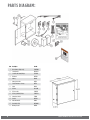
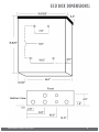
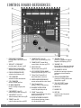
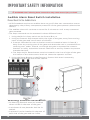
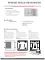
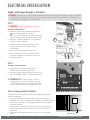
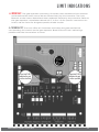
INSTALLATION
INSTRUCTIONS
AND SAFETY INFORMATION
FOR THE VIKING SINGLE CONTROL UNIT
CLASS II, CLASS III, AND CLASS IV
Commercial/Residential Vehicular
Swing Gate Control Unit
This Single Electronic Control Unit “ECUS” is equipped for use with
115/230VAC, 24VAC/VDC or solar and includes a battery backup
system and Viking’s new “VFlex” control board. The VFlex control
board offers enhanced surge/lightning protection, state of the art
technology and a user-friendly design for setup and troubleshooting.
THE VIKING SINGLE ELECTRONIC CONTROL UNIT
ECU Single Vehicular Swing Gate Controller • Revision ECUSNXMN10.G • September 2013
PARTS DIAGRAM:
Item Description
2
Part No.
1
Motor Harness (Single only)
ECUMTHRN
2
Power Harness
DUPHCECU
3
Control Board (Master/Single)
VFLEXPCB
4
EMI Board
DUEMI10
5
Battery
DUBA12
6
Battery Fuse Holder
VABFH
7
Toroid Transformer - 10 amp
DUTT10
8
Alarm
DUAL10
9
ECU Box
VA-ECUBB
10
ECU Access Key
ECUKEY20
11
ECU Key Cylinder W/ 2 Keys
ECUKEYC20
12
Alarm Reset Switch
ECURW
13
Fuse Kit
DUFSK10
14
Radio Antenna Kit
VARAK
15
Strain Relief (ECU)
DH3/4NMCC
16
Warning Placard
DUWPA
VIKING TECHNICAL SUPPORT 1.800.908.0884
ECU BOX DIMENSIONS:
VIKING TECHNICAL SUPPORT 1.800.908.0884
3
CONTROL BOARD REFERENCES:
1. POWER HARNESS CONNECTOR
provides power to the control board.
pg 14-15
2. “OPEN LEFT” & “OPEN RIGHT”
provides power to the motor. pg 16
3. INACTIVE FOR ECU APPLICATIONS
available for future developments
4. FEATURE ACTIVATION TRIM POTS
activate and set features. pg 18
5. “EPS1” CONNECTOR
available for future developments
6. “EPS2” CONNECTOR monitors the limit positions.
7. EMI BOARD CONNECTOR
monitors the high voltage power
supply.
8. “CHECK MOTOR” Status LED
indicates motor power status. pg 30
9. “LOW BATTERY” Status LED
indicates battery power status. pg 30
10. “POWER” Status LED
control board power status. pg 14,30
4
11. “MAGNETIC LOCK” Status LED
status of this on-board relay. pg 27, 30
12. “MAGNETIC LOCK” Terminal Block
connect electric locks here. pg 27, 30
13. INPUT STATUS LEDS
indicates input status. pg 30-31
14. ACCESS CONTROL TERMINAL BLOCKS
accessory connections. pg 22-25, 36-38
15. “Master/Slave” Terminal Block
wired master/slave connection.
16. CONTROL BOARD MOUNTING HOLES
secures and grounds the control board.
17. “Siren” Terminal Block
Vikings UL Siren is connected here.
18. ON-BOARD 3 BUTTON STATION
controls the gate during set up.
19. “BRAKE” Terminal Block
used for solar applications & in-motion
warning devices. pg 15, 19
21. “DIAGNOSE” Button
allows you to navigate through the
Diagnostics LCD Display. pg 32-34
22. “DIAGNOSE” LED
informs that errors have been detected
and available on LCD Display. pg 32-34
23. LCD DIAGNOSTICS DISPLAY
provides error messages, diagnostics
and operator status information.
pg 32-34
24. VIKING ADD-ON CONNECTIONS
connections for Viking Konnect and
Viking Monitor. pg 40
25. “FAIL SAFE/SECURE” Jumper
power failure option. pg 19
26. MOTOR FUSE
27. CHARGER FUSE
28. HEAT SINK
secures the control board and
dissipates heat.
20.FEATURE ACTIVATION PIN HEADERS
active features by placing a jumper
onto the pin headers. pg 19
VIKING TECHNICAL SUPPORT 1.800.908.0884
TABLE OF CONTENTS:
PARTS DIAGRAM/PARTS LIST
ECU BOX DIMENSIONS
CONTROL BOARD REFERENCES
IMPORTANT SAFETY INFORMATION
Important Safety Instructions
Important Installation Instructions
Maintenance
General Safety Precautions
Operator Classification
Photo Beam (non-contact sensor) Installation
Edge Sensor (contact sensor) Installation
Audible Alarm Reset Installation
Warning Placard Installation
IMPORTANT INSTALLATION INFORMATION
Specifications
ECU Box Installation
ELECTRICAL INSTALLATION
High Voltage Supply Option
Low Voltage Supply Option
Solar Supply Option
Motor Harness
LIMIT INDICATIONS
CONTROL BOARD SETUP
2
3
4
6-12
6
7
8
8-9
9
10
11
12
12
13
13
13
14-16
14
15
15
16
17
18-21
Initial Settings
18-19
Obstruction Detection Sensor (Primary Entrapment Protection)
20
Viking Heater.......................................................................................................................... 21
ACCESSORY CONNECTIONS
Re-Open Photo Beam (Vehicular Safety)
Radio Receiver (Typical)
Anti-Tail Gate, Open Commands, Guard Station
Viking Loop Rack
Guidelines for Loop Installations
Magnetic Lock, Lock Solenoid
Barrier Arm (B-12) Synchronization Option
TROUBLESHOOTING
22-28
22
23
24
25
26
27
28
30-35
LED References
LCD Display References
Solutions
30-31
32-34
35
APPENDIX A, B & C
VIKING EXPANSION PRODUCTS
36-39
40
VIKING TECHNICAL SUPPORT 1.800.908.0884
5
IMPORTANT SAFETY INFORMATION
! WARNING! Not Following these instructions may cause severe injury or death.
IMPORTANT SAFETY INSTRUCTIONS
! WARNING! To reduce the risk of severe injury or death.
1. READ AND FOLLOW ALL INSTRUCTIONS .
2. Never let children operate or play with gate controls. Keep the remote away
from children.
3. Always keep people and objects away from the gate. NO ONE SHOULD
CROSS THE PATH OF THE MOVING GATE.
4. Test the gate operator monthly. The gate MUST reverse on contact with
a rigid object or when an object activates the non-contact sensors. Af ter
adjusting the force or the limit travel, retest the gate operator. Failure to
adjust and retest the gate operator properly can increase the risk of injury or
death.
5. Use the manual release only when the gate is not moving.
6. KEEP GATES PROPERLY MAINTAINED. Read the owners manual. Have a
qualified service person make repairs to gate hardware.
7. The entrance is for vehicles only. Pedestrians must use a separate entrance.
8. Every gate operator installation MUST have secondary protection devices
against entrapment, such as edge sensors and photo beams more in
particularly in places where the risk of entrapment is more likely to occur.
9. SAVE THESE INSTRUCTIONS .
IMPORTANT INSTALLATION INSTRUCTIONS
1. Install the gate operator only when:
a. The operator is appropriate for the construction of the gate and usage
Class of the gate (refer to page 5),
b. All openings of a horizontal slide gate are guarded or screened from the
bottom of the gate to a minimum of 4 feet (1. 22 m) above the ground to
prevent a 2-1/4 inch (57. 2 mm) diameter sphere from passing through the
openings anywhere in the gate, and in that portion of the adjacent fence
that the gate covers in the open position,
c. ALL EXPOSED PINCH POINTS ARE ELIMINATED OR GUARDED, AND
d. GUARDING IS SUPPLIED FOR EXPOSED ROLLERS .
2. The Operator is intended for installation only on gates used for vehicles.
Pedestrians must be supplied with a separate access opening. The pedestrian
access opening shall be designed to promote pedestrian usage. Locate the
gate such that persons will not come into contact with the vehicular gate
during the entire path of travel of the vehicular gate.
3. The gate must be installed in a location so that enough clearance is supplied
between the gate and adjacent structures when opening and closing to
reduce the risk of entrapment. Swinging gates shall not open in to the public
access areas.
4. The gate must be properly installed and work freely in both directions prior to
the installation of the gate operator. Do not over-tighten the operator clutch
or pressure relief valve to compensate for a damaged gate.
5. The gate operator controls must be placed so that the user has full view of
the gate area when the gate is moving AND AWAY FROM THE GATE PATH
PERIMETER.
6
VIKING TECHNICAL SUPPORT 1.800.908.0884
IMPORTANT SAFETY INFORMATION
! WARNING! Not Following these instructions may cause severe injury or death.
IMPORTANT INSTALLATION INSTRUCTIONS (Continued)
6. Controls intended for user activation must be located at least six feet (6’)
away from any moving part of the gate and where the user is prevented from
reaching over, under, around or through the gate to operate the controls.
Outdoor or easily accessible controls shall have a security feature to prevent
unauthorized use.
7. The Stop and/or Reset button must be located in the line-of-sight of the gate.
Activation of the reset control shall not cause the operator to start.
8. All warning signs and placards must be installed where visible in the area of the
gate. A minimum of two placards shall be installed. A placard is to be installed
in the area of each side of the gate and the gate be visible to persons located
on the side of the gate on which the placard is installed.
9. For gate operators using non-contact sensors (Photo Beams or like) in
accordance with section 31.1.1 of the UL standard:
a. The operator is appropriate for the construction of the gate and usage
Class of the gate (refer to page 5),
b. Care shall be exercised to reduce the risk of nuisance tripping, such as
when a vehicle, trips the sensor while the gate is still moving, and
c. One or more non-contact sensors shall be located where the risk of
entrapment or obstruction exists, such as the perimeter reachable by a
moving gate or barrier (refer to page 6).
d. Use only Omron E3K-R10K4 photoelectric eye to comply with UL 325
10.For a gate operator utilizing a contact sensor (Edge sensor or like) in
accordance with section 31.1.1 of the UL 325 standard:
a. One or more contact sensors shall be located where the risk of entrapment
or obstruction exists, such as a the leading edge, trailing edge, and post
mounted both inside and outside os a vehicular horizontal slide gate (refer
to page 7).
b. One or more contact sensors shall be located at the bottom of a vehicular
vertical lif t gate.
c. One or more contact sensors shall be located at the pinch point of a
vehicular vertical pivot gate.
d. A hardwired contact sensor shall be located and its wiring arranged so
that the communication between the sensor and the gate operator is not
subject to mechanical damage.
e. A wireless contact sensor such as one that transmits radio frequency
(RF) signals to the gate operator for entrapment protection functions
shall be located where the transmission of the signals are not obstructed
or impeded by building structures, natural landscaping or similar
obstructions. A wireless contact sensor shall function under the intended
end-use conditions.
f. One or more contact sensors shall be located on the inside and outside
leading edge of a swing gate. Additionally, if the bottom edge of a swing
gate is grater than 6 inches (152 mm) above the ground at any point in its
arc of travel, one or more contact sensors shall be located at the bottom
edge (refer to page 7).
g. One or more contact sensors shall be located at the bottom edge of a
vertical barrier (arm).
h. Only Use Miller Edge Model MGR20 or MGS20 edge sensor to comply with
UL325
VIKING TECHNICAL SUPPORT 1.800.908.0884
7
IMPORTANT SAFETY INFORMATION
! WARNING! Not Following these instructions may cause severe injury or death.
MAINTENANCE
Remove the Power Harness from the Control Board (refer to page 14)
•Clean and lubricate the turning pins and gate hinges using the recommended
lubricant.
•Check that all mounting hardware of the gate operator is properly tighten.
•Ensure that the gate moves freely.
•Check for corroded parts and replace if necessary.
•Check the battery for the following:
- Battery connections must be free of corrosion.
- Battery voltage must be 26v DC (fully charged battery).
Reconnect the Power Harness for the Control Board (refer to page 14)
•Check and confirm the proper operation of all safety devices (photoelectric
eye, edge sensors or like).
•Check and confirm the operation of all installed accessories.
•Check and confirm the operation of all special features such as the Intelligent
Obstruction Sensor, Hold Open Timer (refer to page 18 and 20)
•Check and confirm the operation of the manual release (See Operator Manual)
•Verif y battery backup functionally by turning of f the power source (120v AC
and 220v AC). DO NOT FORGET TO TURN ON THE POWER SOURCE AFTER
VERIFICATION.
GENERAL SAFETY PRECAUTIONS
The following precautions are an integral and essential part of the product and must be
supplied to the user. Read them carefully as they contain important indications for the
safe installation, use and maintenance.
• These instruction must be kept and forwarded to all possible future users of the
system.
•This product must be used only for that which it has been expressly designed.
•Any other use is to be considered improper and therefore dangerous.
•The manufacturer cannot be held responsible for possible damage caused by
improper, erroneous or unreasonable use.
•Avoid operating in the proximity of the hinges or moving mechanical parts.
•Do not enter the path of the moving gate while in motion.
•Do not obstruct the motion of the gate as this may cause a situation of danger.
•Do not allow children to play or stay within the the path of the moving gate.
•Keep remote control or any other control devices out of the reach of children, in
order to avoid possible involuntary activation of the gate operator.
•In case of break down or malfunctioning of the product, disconnect from the main
power source. Do not attempt to repair or intervene directly, contact only qualified
personnel for repair.
•Failure to comply with the above may create a situation of danger.
•All cleaning, maintenance or repair work must be carried out by qualified personnel.
•In order to guarantee that the system works efficiently and correctly it is important
to have the manufacturer’s instructions on maintenance of the gate and operator
carried out by qualified personnel.
•In particular, regular checks are recommended in order to verify that the safety
devices are operating correctly.
All installation, maintenance and repair work must be documented and made
available to the user.
8
VIKING TECHNICAL SUPPORT 1.800.908.0884
IMPORTANT SAFETY INFORMATION
! CAUTION: To Reduce the Risk of Fire or Injury to Persons:
a. Use only the following type and size battery(ies): Yuasa NP7-12
b. Do not dispose of the battery(ies) in fire. The cells may explode. Check with local
codes for possible disposal instructions.
c. Do not open or mutalate the battery(ies). Released electrolyte is corrosive and may
cause damage to the eyes or skin. It may be toxic if swallowed.
d. Exercise care in handling batteries in order not to short the battery with
conductying materials such as rings, bracelets and keys.
e. Change the battery(ies) provided with or identified for use with this product only in
accordance with the instructions and limitations specified in this manual.
f. Observe proper polarity orientation between the battery(ies) and charging circuit.
g. Do not mix batteries of differ ant sizes or from different manufactures in this
product (applies to products employing more than one user replaceable secondary
battery).
h. A battery-operated product employing a secondary battery supply intended to be
charged within the product shall contain specific instructions concerning the proper
method of charging.
UL325 Gate Operator Classification
GLOSSARY
RESIDENTIAL VEHICULAR GATE OPERATOR
CLASS I - A vehicular gate operator (or system) intended
for use in a home of one-to four single family dwelling,
or a garage or parking area associated therewith.
COMMERCIAL/GENERAL ACCESS VEHICULAR GATE OPERATOR
CLASS II – A vehicular gate operator (or system)
intended for use in a commercial location or building
such as a multi-family housing unit (five or more single
family units), hotel, garages, retail store, or other
building servicing the general public.
INDUSTRIAL/LIMITED ACCESS VEHICULAR GATE OPERATOR
CLASS III – A vehicular gate operator (or system)
intended for use in an industrial location or building
such as a factory or loading dock area or other
locations not intended to service the general public.
RESTRICTED ACCESS VEHICULAR GATE OPERATOR
CLASS IV – A vehicular gate operator (or system)
intended for use in a guarded industrial location or
building such as an airport security area or other
restricted access locations not servicing the general
public, in which unauthorized access is prevented via
supervision by security personnel.
Install the gate operator only when:
The operator is appropriate for the construction of the gate and the Usage Class of
the gate.
VIKING TECHNICAL SUPPORT 1.800.908.0884
9
IMPORTANT SAFETY INFORMATION
! WARNING! Not Following these instructions may cause severe injury or death.
NOTE: This type on installation does not reverse the gate all the way back to
its limits when the photo beam is obstructed. This installation is only to protect
against entrapment and to comply with UL325.
Secondary Entrapment Protection
Photo Beam (non-contact sensor) Installation
•Photo beams or like must be installed to reduce the risk of entrapment.
•Use only Omron E3K-R10K4 photoelectric eye to comply with UL325
•Make the electrical connections of the photoelectric sensor as described here in
this page.
•Care shall be exercised to reduce the risk of nuisance tripping, such as when a vehicle, trips the sensor while the gate is still moving, and;
•One or more non-contact sensors shall be located where the risk of entrapment or
obstruction exists, such as the perimeter reachable by a moving gate or barrier.
Consult the installation manual for the UL325 device (photo beam or like) for detail
information about the usage, installation and maintenance.
10
VIKING TECHNICAL SUPPORT 1.800.908.0884
IMPORTANT SAFETY INFORMATION
! WARNING! Not Following these instructions may cause severe injury or death.
NOTE: This type on installation does not reverse the gate all the way back to
its limits when the edge sensor is obstructed. This installation is only to protect
against entrapment and to comply with UL325.
Secondary Entrapment Protection
Edge Sensor (non-contact sensor) Installation
•Edge Sensors or like must be installed to reduce the risk of entrapment.
•Use only Miller Edge 3-sided activation type MGR20 or MGS20 to comply with
UL325
•One or more contact sensors shall be located on the inside and outside leading
edge of a swing gate. Additionally, if the bottom edge of a swing gate is greater
than 6 inches (152 mm) above the ground at any point in its arc of travel, one or
more contact sensors shall be located on the bottom edge.
1. A hardwired contact sensor shall be located and its wiring arranged so that the
communication between the sensor and the gate operator is not subjected to
mechanical damage.
2. A wireless contact sensor such as one that transmits radio frequency (RF) signals to the gate operator for entrapment protection functions shall be located
where the transmission of the signals are not obstructed or impeded by building
structures, natural landscaping or similar obstruction. A wireless contact sensor
shall function under the intended end-use conditions.
VIKING TECHNICAL SUPPORT 1.800.908.0884
11
IMPORTANT SAFETY INFORMATION
! WARNING! Not Following these instructions may cause severe injury or death.
Audible Alarm Reset Switch Installation
Manual Reset for the Audible Alarm
•UL325 standard requires an audible alarm to go off after two consecutive events
detected by the primary entrapment protection of the gate operator (obstruction
sensor).
•The audible alarm will continue to sound for 5 minutes or until a stop command
gets actuated.
•The Stop command can be actuated in three different forms:
1. Using the Built in Stop switch on the Control Box; or
2. Using an External Stop button within the sight of the gate, away from moving
parts of the gate and out of reach of children.
a. Controls intended for user activation must be located at least six feet (6’)
away from any moving part of the gate and where the user is prevented from
reaching over, under, around, or through the gate to operate the controls.
Outdoor or easily accessible controls shall have a security feature to prevent
unauthorized use.
b.The Stop and/or Reset button must be located in the line-of-sight of the gate.
Activation of the reset control shall not cause the operator to start.
3. Using the Reset Button on the Electronic Control Unit that is externally
accessible on the left side of the cabinet.
2
1
Warning Placard Installation
•All Warning Placards must be installed
where visible in the area of the gate.
•A minimum of two placards shall be installed.
•A placard is to be installed in the area of
each side of the gate and be visible.
12
VIKING TECHNICAL SUPPORT 1.800.908.0884
IMPORTANT INSTALLATION INFORMATION
! WARNING: DO NOT allow pedestrian use of this gate.
Locate Control Buttons:
1. Within sight of the gate,
2. At a minimum height of 5 feet
so small children are not able to
reach it; and
3. At least 6 feet away from all
moving parts of the gate.
Specifications
Power Requirements:
115v / 230v AC (4 amp / 2 amp)
Single Phase (50 Hz / 60 Hz)
24v AC / DC
Solar 24v 80w
ECU Box Installation
STEP 1
STEP 2
STEP 3
Disconnect the Siren
and Stop ButtonLeads
from the Control Board.
Remove the Control
Board Mounting Plate.
The plate is held in the
box by four screws.
Position the ECU Box
in the desired place
and mark the mounting
holes. Prepare the holes
to receive the anchors/
fasteners.
NOTE: Anchors are Not
Supplied.
Position the ECU Box
and secure it to the
mounting surface using
the Sealed Washers
provided (rubber side
of the washers against
the inside of the control
box).
! WARNING: If the control box is not mounted properly
it may fall, causing damage and/or injury. The Electronic
Control Unit (ECU) weight is approximately 40 lbs.
Be sure that the substrate being mounted to and the
fasteners being used are appropriate to support the
weight of the control box.
VIKING TECHNICAL SUPPORT 1.800.908.0884
Mounting Fastener
(Customer supplied)
sealed Washer
(supplied with Unit)
Control Box
Mounting surface
13
ELECTRICAL INSTALLATION
High Voltage Supply Option
! Caution: Always turn off power breakers when working with high voltage. DO NOT
connect the “Power Harness” to the Control Board until the electrical installation is
complete and ready for verification.
STEP 1
! WARNING: SINGLE PHASE AC ONLY
At the “EMI Board”:
a.Remove the Control Board Mounting
Plate as described on page 13.
TIP: It is not nessesary to dismount the
control board from the Mounting Plate
b. Set the “Voltage Selector” according
to the voltage supply.
1
c. Connect the incoming power wires
to the terminals as shown in the
illustration.
d.Turn the main breaker back ON.
e. Verify that all three (3) Status LEDs
are illuminated on the front panel of
the Power Box.
2b
STEP 2
At the Control Board:
a. Reinstall the Control Board and
Control Board Mounting Plate.
b. Connect the Power Harness and verify
that “POWER” LED is illuminated solid.
! TECHNICAL TIP: If the “Power” LED is
flashing or any of the 3 LEDs on the
“EMI Board” are not illuminated, refer
to the Troubleshooting pages 30-35.
Tips for proper ground installation:
To minimize the effects caused by lightning, follow
these guidelines.
• Use a ground rod to provide a ground reference.
• Consult your city code and be aware of under-ground
services in the site of the gate operator to prevent
inconveniences.
• Always use a single bonding point for grounding.
• All ground wires must be as short and as thick as
possible.
• Prevent unnecessary turns or loops in all ground
wires.
14
Ground Rod
VIKING TECHNICAL SUPPORT 1.800.908.0884
ELECTRICAL INSTALLATION
Low Voltage Supply Option
TIP: As an alternative to high voltage, the operator can be power by 24VAC. It is
recommended to use Vikings Modular Power Box (part # VNXMPB) as the source.
! Caution: Always turn off power breakers when working with high voltage. DO NOT
connect the “Power Harness” to the Control Board until the electrical installation is
complete and ready for verification.
Install the “Modular Power Box” at the nearest high voltage source (115v or 230v single
phase) and connect to the controller’s Power Harness. Follow local codes or guidelines.
MAXIMUM DISTANCE:
1000 ft. with 10 AWG wire
Solar Supply Option
Vikings Solar Package (part # VA-SOCHP) is an efficient and effective solution to
powering the operator with solar energy. (See page 40 for package details)
! Tip: For increased solar efficiency:
By activating the “Pre-Warning”
feature A , the “Brake” terminals B
will provide power to all non-essential
controls beginning 3 seconds prior to
gate movement and while the gate is
moving. (page 19)
A
B
Connect the two
panels in series.
Connect the batteries
in series.
Disconnect the operators
power harness and use the
Solar Harness.
! IMPORTANT: The number of cycles achieved daily is dependent on the average solar
radiation of the geographic location and the power consumption of all accessories
being used. Increased panel and battery capacities may be required. See Appendix C
on page 39 for more important information regarding solar applications.
VIKING TECHNICAL SUPPORT 1.800.908.0884
15
ELECTRICAL INSTALLATION
Motor Harness
NOTE: Refer to the gate operator’s Installation Manual (G-5, X-9 or i-8) for specific
instructions on how to connect the gate operator’s wiring harness to the operator.
STEP 1
Connect the wires from the operator’s
wiring harness to the terminal block
mounted next to the control board.
Match wire colors to the terminal block.
! Tip: If this controller is an i-8 model
ECU, the blue and black wires from
the operator’s wiring harness are only
required to be connected.
STEP 2
Connect the ground wire, (bare or noninsulated wire) from the operator’s wiring
harness, to both the Chassis of the ECU
and the gate operator.
STEP 3
Connect the “Motor Harness” to the Control Board.
For G-5 operator
a. “OPEN RIGHT” Connector if the gate opens to the INSIDE (pull to open).
b. “OPEN LEFT” Connector if the gate opens to the OUTSIDE (push to open).
For X-9 and i-8 operators
a. “OPEN RIGHT” Connector if the gate opens Inside to the Right or Outside to the Left.
b. “OPEN LEFT” Connector if the gate opens Inside to the Left or Outside to the Right.
G-5
16
X-9 & i-8
VIKING TECHNICAL SUPPORT 1.800.908.0884
LIMIT INDICATIONS
! IMPORTANT: The gate operator (excluding i-8 model) uses mechanical limit switches
and therefore the limits cannot be set electronically by this controller. The Limit
Buttons on the control board have been rendered inactive by the controller. Refer to
the gate operator’s Installation Manual (G-5, X-9 or i-8) for specific instructions on
how to set the limits for the gate operator model chosen.
VIKING TECHNICAL SUPPORT 1.800.908.0884
Close
Limit
“Close Limit” LED
indictates the gate
is at the close limit.
Open
Limit
! TECHNICAL TIP: The Limit LEDs will illuminate solid when the gate reaches the
corrisponding limit switch on the gate operator. Both LEDs will flash. indicating a
problem with the limt switches or wires.
“Open Limit” LED
indictates the gate
is at the open limit.
17
CONTROL BOARD SETUP
Initial Settings
“Timer”
Hold Open Timer
“Overlap”
Overlap Delay
Automatically closes the gate after
the selected amount of time from 1-60
seconds.
Delays the gate from opening for the
selected amount of time from 1-6
seconds.
Turning the dial to between “0” and
“OFF” will disable this feature, requiring
a close command to close the gate.
“ODS”
Obstruction Detection Sensor
Sets the amount of force required to trip
the inherent obstruction sensor.
See page 20 for more details about this
feature.
18
“Speed”
Motor Speed
Increases or decreases the speed of gate
travel.
VIKING TECHNICAL SUPPORT 1.800.908.0884
CONTROL BOARD SETUP
Initial Settings
NOTE: Installing a shunt, or jumper, on the pins will activate the feature.
“Auto Open” - Power Failure Option
Opens the gate automatically during
power failure. Resumes normal operation
when power is restored.
“Last Open” - Power Failure Option
Will open the gate automatically when
batteries critically low.
“Fail Safe/Secure”
During complete power
failure, including battery
power; determines the force
required to manually move
the gate.
•Fail Safe Mode: (G-5 Only)
By removing the wirejumper plug from the “Fail
Safe/Secure” connector:
The gate can move
manually with a relatively
low amount of force.
•Fail Secure Mode:
By inserting the wirejumper plug into the “Fail
Safe/Secure” connector:
The gate will not move
manually.
VIKING TECHNICAL SUPPORT 1.800.908.0884
“Pre-Warning” Initiates two options for
an audio or visual warning 3 seconds
prior to gate motion and will continue:
1. Until gate reaches closed limit:
“Magnetic Lock” terminals provide a
contact between “COM” and “N.O”.
2. While gate is moving:
“Brake” terminals provide a 24v DC.
“Sync” Used only in conjunction with
the Viking Barrier gate operator model
B-12. Activating this feature allows for
synchronized operation with the B-12
operator. See page 28.
“EXT” Available for future developments.
19
CONTROL BOARD SETUP
Obstruction Sensor (Primary Entrapment Protection)
! IMPORTANT: The appropriate “ODS” setting is dependant upon the gate installation
and construction. Set this feature accordingly. Additional Safety equipment should
be used to reduce possible risk of injury or vehicle damage.
“ODS” Obstruction Detection Sensor
The Obstruction Sensor detects
obstructions in the path of the traveling
gate. The dial sets the amount of force
required to activate the operators inherent
obstruction detection.
Setting the dial to “0” will require the least
amount of force to activate;
Setting the dial to “100” will require the
maximum amount of force to activate.
UL325 standard requires an audio
alarm to go off after two consecutive
entrapment events sensed by the
Inherent Entrapment Protection of the
Gate Operator.
When the Obstruction Sensor detects
an obstruction it will:
1. Stop the gate’s movement and reverse
it momentarily.
2. Bring the gate to a resting position.
3. Disable the Hold Open Timer feature
until the Gate Operator receives a new
command.
If second obstruction is detected before
the gate reaches either limit it will:
1. Stop the gate’s movement.
2. Disable the Gate Operator.
3. Sound the UL Alarm
4. A STOP command must be provided
to disable the alarm and continue
operation.
The audio alarm will sound for a period
of 5 minutes or until the “Stop” Button
or “Alarm Reset” Button is pressed. See
page 12 for more information.
! TECHNICAL TIP: The Status LED for the
“ODS” will indicate the following
when it has been triggered.
A. Solid: Obstruction.
Detected a sudden or abrupt increase
in gate resistance.
B. Flashing: Overload.
Detected a more subtle, but sustained
increase in gate resistance.
20
VIKING TECHNICAL SUPPORT 1.800.908.0884
CONTROL BOARD SETUP
Viking Heater
The operator has an integrated heater. Activate this feature when the operator is used in
application temperatures down to -20°F (-29°C).
To set the heater to turn on at the Close Limit:
1. Use the “Diagnose” button to scroll through the LCD
menu to “HEATER CLS”
2. Press and hold the “Stop” button on the control board.
3. Press and release the “Diagnose” button to turn this
feature ON and OFF.
To set the heater to turn on at the Open Limit:
1. Use the “Diagnose” button to scroll through the LCD
menu to “HEATER OPN”
2. Perform steps 2-3 as described above.
HEATER
CLS ON
HEATER
OPN ON
NOTE: If the application requires the gate to be held open for any reason, set the HEATER
ON for both limit positions.
! IMPORTANT: A POSITIVE STOP must be used on the gate at the limit position(s) the
HEATER has been set for.
VIKING TECHNICAL SUPPORT 1.800.908.0884
21
ACCESSORY CONNECTIONS
Re-Open Photo Beam (vehicular Safety)
NOTE: This type of photo-beam installation will stop then RE-OPENS the gate all the way
to the open limit when the an beam is obstructed. Intended for vehicular safety ONLY.
For the purpose of pedestrian entrapment, see pages 10-11.
N.O.
COM
(-)
(+)
Note regarding Photo Beam types:
Check for proper operation:
Fail-Safe type - connect the “N.C.”
terminal of the photo beam to the
“Re-Open” terminal on the control board.
The “Re-Open” LED will illuminate
solid while the beam is obstructed
and remain off when the beam is
unobstructed.
Typically, these are the reflective type
photo beams.
Fail -Secure type - connect the “N.O.”
terminal of the photo beam to the
“Re-Open” terminal on the control board.
Typically, these are the transmitter/
receiver type photo beams.
22
! TECHNICAL TIP: For more information
regarding accessory connections
to the control board and individual
input terminal functions, refer to
“Appendix (A)” pages 36-37.
VIKING TECHNICAL SUPPORT 1.800.908.0884
ACCESSORY CONNECTIONS
Radio Receiver (Typical)
! IMPORTANT: The Hold Open “Timer” setting (page 18) effects how the gate will
respond to the radio receiver command.
The control board provides two modes
of operation that a radio receiver can
control the gate:
Open-Stop-Close
1. By having the radio receiver connected
as illustrated and with the Hold Open
Timer OFF (see page 18):
COM
N.O.
(-)
(+)
Every command of the radio transmitter
will control the gate as follow:
a. First command opens the gate,
b. Second command stops the gate and
c. Third command closes the gate
d. Any subsequent commands will
continue in the same order to control
the gate.
This type of configuration is not
recommended for a commercial
installations.
Open Only
2. By having the radio receiver connected
as illustrated and with the Hold Open
Timer ON (see page 18):
Each command of the radio transmitter is
ALWAYS AN OPEN COMMAND
to the gate.
For maximum reception range:
Locate the radio antenna to
the top of the gate column.
! TECHNICAL TIP: For more information
regarding accessory connections
and terminal functions, refer to
“Appendix (A)” on pages 36-37.
See “Appendix (B)” on page 38 for
connecting common radio receiver
models.
VIKING TECHNICAL SUPPORT 1.800.908.0884
23
ACCESSORY CONNECTIONS
Anti-Tail Gate, Open Commands & Guard Station
! TECHNICAL TIP: For more information regarding accessory connections and terminal
functions, refer to “Appendix (A)” on pages 36-37.
Open Commands
“Exit ”, “Fire” and “Strike” input terminals
all provide an open command to the
control board. Any device connected as
shown will open the gate.
+ + -
+
-
N.O.
COM
N.O.
COM
N.O.
COM
Guard Station
! All three buttons must be a
Normally Open “N.O.” type of
switch, and can share the same
common “C” connection to “GND”.
“ATG” Anti-Tailgate
This input will stop the
gate when the vehicle
triggers the sensor, then
closes the gate when the
vehicle leaves the sensor,
preventing unauthorized
vehicles from entry.
+
-
COM
N.O.
24
VIKING TECHNICAL SUPPORT 1.800.908.0884
ACCESSORY CONNECTIONS
Viking Loop Rack
TIP: This operator may be equipped with a pre-wired Loop Rack that plug-in type loop
detectors can be connected to. This provides a convenient alternative to the box
type loop detectors that would need to be wired to the control board. Viking does
not provide either type of loop detectors.
Loop Rack: Part # VA-LR Loop Rack Wiring Harness: Part # VA-LRH
VIKING TECHNICAL SUPPORT 1.800.908.0884
25
ACCESSORY CONNECTIONS
Guidelines for Loop Installation
1. Prevent sharp corners in the geometry of the loop sensor.
2. Install the appropriate number of turns for your loop geometry based on the loop
perimeter. Use Table C (below) as a guide.
3. Use XLP (cross-linked-polyethylene) type of wire. This wire reduces the effects
of moisture and other environmental events in altering the functionality of the
vehicular loop detector.
4.Twist the lead wire at least 6 turns per foot.
5. Use BACKER-ROD to minimize damage to the loop detector wire prior to using the
sealant.
6.Place the loop detector wire and adjust the sensitivity of the vehicular loop
detector unit in a way to minimize the effects of the gate over the loop detector
wire.
! IMPORTANT! Some of the following parameters may affect the proper
functionality of the vehicular loop detector.
Consult the manufacturer of the vehicular loop detector and/or loop wire.
• Gate size
• Number of turns in the loop sensor wire
• Distance of the loop sensor wire to the gate at either at the open or close position
Table C - Recommended Number of Turns
Perimeter (ft.)
Number of Turns
105
204
30-403
50-1002
Dimension “A” - 5’ for Single Gate
6’ for Dual Gate
5'
A
Outside
Reopen
Loop
5'
A
Center
Loop
5'
5'
Inside
Reopen
Loop
Exit
Loop
Make Even
with Open Gate
Gate in Open Position
26
VIKING TECHNICAL SUPPORT 1.800.908.0884
ACCESSORY CONNECTIONS
Magnetic Lock, Lock Solenoid
NOTE: Viking Access Systems does not provide external gate lock devices. These items
can be purchases from your dealer or distributor.
Power
Magnetic Lock
Do not use the 24v DC power supplied
by the control board. An external power
supply, or plug-in transformer, must
be used for the magnetic lock or lock
solenoid.
This will prevent rapid drainage of the
battery in the event of power failure.
The control boards “Magnetic Lock ” relay
is rated for 10A-250v AC .
(+)
(+)
Lock Solenoid
(+)
(+)
VIKING TECHNICAL SUPPORT 1.800.908.0884
27
SYNCHRONIZATION WITH B-12
Barrier Arm (B-12) Synchronization Option
NOTE: The Control Board provides a convenient solution for applications that require
synchronized operation with the Viking Barrier Arm Operator model B-12.
This type of application opens and closes in the follow pattern:
1. Open Command is provided only to the Viking B-12 Barrier Arm Operator.
2. The Barrier Arm will delay to open until this Gate Operator reaches its Open Limit.
3. The Gate Operator will delay to close until the Barrier Arm reaches its Close Limit.
STEP 1 (Figure A & B)
STEP 2 (Figure A)
Connect the Gate Operator to the Viking
B-12 Barrier Arm Operator as illustrated.
At the B-12 Barrier Arm Operator,
connect the primary device that will be
used as the OPEN input.
STEP 3 (Figure B)
Figure B
On the Gate Operator Control Board,
activate Sync Mode by placing a jumper
on to the pin headers labeled “SYNC”.
Figure A
1
2
3
Figure D
STEP 4 (Figure C & D)
Connect Viking B-12 Barrier Arm
Operator to the Gate Operator as
illustrated.
Figure C
4
28
VIKING TECHNICAL SUPPORT 1.800.908.0884
(THIS PAGE LEFT BLANK INTENTIONALLY)
VIKING TECHNICAL SUPPORT 1.800.908.0884
29
TROUBLESHOOTING
LED References
In addition to the LCD Display, the control board LEDs monitor the various circuits of the
control board. Use the table below to identify the corresponding “TS Ref#” and refer to
page 32-35 for further troubleshooting.
Page 35
TS Ref#(s)
# LED
Status
Meaning
1
OFF
At Closed Limit and Magnetic Lock Relay state is closed across “COM” &
“N.C”. (page 27). Gate should be at the Close Limit.
SOLID
Not at Closed Limit and Magnetic Lock Relay state is closed across “COM” &
“N.O”. (page 27). Gate should not be at the Close Limit
2
“Magnetic
Lock”
“Check Motor” OFF
SOLID
3
4
5
6
7
8
30
“Battery Low” OFF
“POWER”
“Radio”
“UL”
“Re-Open”
“ATG”
Normal Condition.
The control board is sending power to the motor but this circuit is not
complete or closed.
7, 8
Normal Condition.
SOLID
Batteries are low. Check power supply to the operator. (pages 14-15).
1, 2
FLASHING
Batteries critically low. Check power supply to the operator. (pages 14-15).
1, 2
SOLID
Normal Condition.
FLASHING
Operator is running on batteries only (pages 14-15).
OFF
No power to control board.
OFF
Normal Condition.
SOLID
Control Board is receiving an input from a device connected to the
Radio terminal (pages 23, 36).
OFF
Normal Condition.
SOLID
Control Board is receiving an input from a device connected to the UL
terminal (pages 12-13, 36).
OFF
Normal Condition.
SOLID
Control Board is receiving an input from a device connected to the ReOpen terminal (pages 22, 25, 36).
OFF
Normal Condition.
SOLID
Control Board is receiving an input from a device connected to the ATG
terminal (pages 24, 36).
1, 2
1, 2, 4, 5
9, 10
9, 10
9, 10
9, 10
VIKING TECHNICAL SUPPORT 1.800.908.0884
TROUBLESHOOTING
LED References
Use the table below to identify the corresponding “TS Ref#” and refer to page 32-35 for
further troubleshooting.
Page 41
TS Ref#(s)
# LED
Status
Meaning
9
OFF
Normal Condition.
SOLID
Control Board is receiving an input from a device connected to the
C Loop terminal (pages 32, 42).
OFF
Normal Condition.
SOLID
Control board is receiving an input for a device connected to any of
the following input terminals: Exit, Fire, Strike or Open (pages 31, 42).
OFF
Normal Condition.
SOLID
Control Board is receiving an input from a device connected to the
Stop terminal (pages 31, 42).
OFF
Normal Condition.
SOLID
Control Board is receiving an input from a device connected to the
Close terminal (pages 31, 42).
OFF
Normal Condition.
SOLID
Second consecutive obstruction has been detected. (page 26).
FLASHING
Batteries are critically low.
OFF
No voltage output on these terminals at the moment.
SOLID
There is 24v DC output on these terminals at the moment.
OFF
Normal Condition
FLASHING
Errors have been detected; Check LCD Display for messages (page 38-40).
OFF
Gate is not at the close limit position.
SOLID
Gate is at the close limit position.
FLASHING
Indicates a problem with the limit switches or wires
OFF
Gate is not at the open limit position.
SOLID
Gate is at the open limit position.
FLASHING
Indicates a problem with the limit switches or wires
OFF
Normal Condition.
SOLID
Obstruction has been detected. (page 26).
11, 13, 1, 2
FLASHING
Overload has been detected. (page 26).
11, 13, 1, 2
RAPID
Control board settings have been overwritten by a Viking wireless device.
OFF
The close timer is turned OFF or gate is not at the open limit if the timer is
turned ON. (page 24).
SOLID
Gate is at Open Limit, Timer is turned ON and counting down to close.
(page 24).
FLASHING
Gate is at Open Limit, Timer is turned ON but is not timing out due to a
conflicting command. (page 24).
SOLID
Normal Condition.
OFF
There is no output voltage from the Modular Power Box.
“C Loop”
10 “Open”
11
“STOP”
12 “Close”
13 “Siren”
14 “Brake”
15
16
17
18
19
“Diagnose”
“Close Limit”
“Open Limit”
“ODS”
“Timer”
20 “AC VOLTAGE OUTPUT”
21
“PROTECTION WORKING” SOLID
22 “AC VOLTAGE INPUT”
9, 10
9, 10
9, 10
11, 13, 1, 2
1, 2
6
6
19
9, 10
2
Normal Condition.
OFF
EMI Board is damaged and circuit is not protected . Replace EMI Board.
SOLID
Normal Condition.
OFF
Incoming power to Modular Power Box is not sufficient.(page 18).
VIKING TECHNICAL SUPPORT 1.800.908.0884
9, 10
1
31
TROUBLESHOOTING
LCD Display References
The control board is equipped with a LCD Display that provides operator information,
current conditions, settings, diagnostics and error messages. Use the table below to
identify the corresponding “TS Ref#” and refer to page 35 for further troubleshooting.
1. Error Messages will be displayed first.
Call out LCD Display, Diagnose Button and Diagnose LED
2. The”Diagnose” LED will flash consecutively
indicating how many Error Messages are
available.
3. Press the Diagnose button to manually
scroll through all of the Messages.
Page 35
TS Ref #s
LCD MSG Meaning
VIKING
ACCESS
MODEL
__
Welcome Message
Indicates the Model of the unit. G5, X9 or I8
System Status Messages
GATE IS
IDLE
GATE IS
OPENING
GATE IS
CLOSING
GATE IS
OPENED
GATE IS
CLOSED
STOP BY
OBSTRUCT
STOP BY
OVERLOAD
OVERLAP
TIMING
HOLDING
__ SEC
32
Gate is stopped between limits
Gate is opening
Gate is closing
Gate is at the limit open position
Gate is at the limit close position
11, 12,
13
Gate stopped due to an obstruction sensor event
Gate stopped due to an overload of the gate system
11, 12
Gate is waiting for the overlap time
Gate is at the limit open position and timing to close - The display shows
the actual time left - prior to time-out
VIKING TECHNICAL SUPPORT 1.800.908.0884
TROUBLESHOOTING
LCD Display References
LCD MSG Meaning
Multi Meter Displays
MOT AMP
__._ A
MOT VOLT
__._ VDC
AC VOLT
__._ VAC
CHARGE
__._ VDC
BAT VOLT
__._ VDC
Page 35
TS Ref #s
This is the motor current amperage during operation
This is the actual motor voltage during operation
This is the actual low voltage AC to the Control Board from the transformer
This is the charging voltage to the batteries
This is the charging voltage when Battery Switch is OFF or the battery
voltage when the low voltage AC is discontinued to the Control Board
Board Settings Messages
Speed
xx%
OVERLAP
_._ SEC
ODS SENS
___%
TIMER
__ SEC
HEATER
CLS OFF
HEATER
CLS ON
HEATER
OPN OFF
HEATER
OPN ON
Shows the percentage of speed set by the Speed adjustment on the control
board. (pg. 18)
Shows the number of seconds set by the Overlap Adjustment on the control board. This feature is not available on slide gate operator models
Shows the amount of force required to trip the obstruction sensor. (pg. 18,
20)
Shows the time delay to hold the gate open at the limit open position,
before starts closing the gate. (pg. 18)
The Integrated Heater has been disabled for the Closed Limit (pg. 21)
The Integrated Heater has been enabled to turn on at the Close Limit
position (pg. 21) “*” will be displayed while it is heating
The integrated Heater has been disabled for the Open Limit (pg. 21)
The Integrated Heater has been enabled to turn on at the Open Limit
position (pg. 21) “*” will be displayed while it is heating
VIKING TECHNICAL SUPPORT 1.800.908.0884
33
TROUBLESHOOTING
LCD Display References
Page 35
TS Ref #s
LCD MSG Meaning
Error Messages
ERR AC
LOW
ERR AC
HIGH
ERR AC
NO AC
ERR CHRG
HIGH
ERR CHRG
CHECK 4A
ERR BAT
LOW
ERR FUSE
15 AMP
ERR EMI
NO EMI
ERR EMI
NO FUSE
ERR EMI
NO AC
ERR EMI
PROTECT
34
Indicates the AC line is low in voltage - AC voltage is below 90 VAC (or 180
VAC for 220 VAC operation).
1, 3, 4
Indicates the AC line is high in voltage - AC voltage is above 130 VAC (or
260 VAC for 220 VAC operation).
1, 3
There is no AC voltage detected to the EMI Board from the 115/230 supply
1
Potential problem with the charging voltage from the control board.
1, ?
a) 4 Amp Fuse is blown
b) or there is a problem with the control board
18, ?
The battery is low
1, 2, 3,
4
15 Amp motor fuse is blown
7, 11, 12
No EMI board detected
15
4 Amp main fuse is blown on Power Supply Panel Assembly
2
There is no AC voltage detected from the EMI Board
20
Lightning strike protection for the EMI Board has been damaged
?
VIKING TECHNICAL SUPPORT 1.800.908.0884
TROUBLESHOOTING
Solutions
Begin the troubleshooting process by referring to the error messages on the LCD
Display and/or the Status LEDs on the control board. Use pages 30-34 to identify
the Troubleshooting Reference # (TS Ref#) then reference the table below.
TS Ref# CHECK
1
Page Ref#
Check that the high voltage power supplied to “EMI Board” is within range.
100v-120v or 200v-240v
pg. 14
2
Remove and check EMI Fuse for continuity.
pg. 14
3
Check that the “Voltage Selector”, on the EMI Board, is set according to the high
voltage power supply. 115v AC or 230v AC
pg. 14
4
Not applicable to this model
5
Check that the Power Harness is connected to the control board.
6
Check that the limit circuits are Normally Closed (N.C.). Check the limit switch.
7
Check Motor Fuse on the control board.
8
Check that the operator is not in Manual Release mode
9
Check the Status LEDs to determine if the control board is receiving an input
from any external devises or if the “ODS” has been triggered.
10
Remove the external devices from the control board to determine if the control pg. 22-25,
board is responding to an input or problem with the external device or wiring.
30-31
11
Check the “ODS” setting on the control board.
pg. 12, 20
12
Check that the gate can be move manually with low resistance throughout its
full range of motion.
pg. 8
pg. 4, 14
pg. 4
pg. 20,
22-25,
30-31
13
Check the limit position.
14
Not applicable to this model
15
Check the EMI cable is properly connected to the “EMI” Connector on the
control board.
pg. 4
16
Check the LCD Display for Error Messages
pg. 34
17
Not applicable to this model
18
Check 4 Amp fuse on the control board
19
Manually adjust any setting on the Control Board to clear all wireless override
settings
20
Check for 24VAC out from the Toroidal Transformer and Power Harness
?
pg. 4
pg. 4, 14
The Control Board or EMI board may be damaged. Call Viking Techical Support
for further assistance
VIKING TECHNICAL SUPPORT 1.800.908.0884
35
Appendix (A)
Access Control Connections
Power Connections
The control board provides a 24v DC output to power external devices and controls.
Alternatively, for devices that require a power supply other than 24v DC , the
operators Power Box contains a convenient 120v AC receptacle to connect a plug-in
transformer.
Terminals Connections and Input Functions:
Viking Terminal
“+28v”
“GND”
“GND”
“Radio”
Function
“C”
“N.O.”
=
=
Common
Normally Open
Device Terminal
--------------------DC Positive
----------------------------------DC Negative
----------------------------------Relay Common
--------------------------------------------------------------------------If “Timer” OFF:
Open - Stop - Close
If “Timer” ON:
Open / Stop while closing
“UL” (see pages 10 & 11)
If Input is brief:
Stops gate then Reverses 12 inches
If input is longer:
Stops gate, does not reverse
“Re- Open”
If stopped:
No function
If closing:
Stops then Opens gate
“ATG” Anti-Tailgate
Input is received:
Stops gate if closing
Input is released:
Closes gate to prevent tailgating
“C. Loop”
If not at open limit:
No function
If at open limit:
Prevents gate from Closing
“Open”, “Exit”, “Fire” & “Strike”
If stopped:
Opens gate
If closing:
Stops then Opens gate
“Stop”
If traveling:
Stops gate
“Close”
If stopped:
Closes gate
If traveling:
No function
“+”
“– ”
“C”
“N.O.”
“N.O.”
“N.O.”
“N.O.”
“N.O.”
“N.O.”
“N.O.”
“N.O.”
! TECHNICAL TIP: Each input Terminal (i.e. Radio, Exit, Re-Open, UL) has a corresponding
Status LED that when illuminated indicates an input is currently being provided to the
terminal and the gate is responding accordingly. (See pages 30-31 LED References)
36
VIKING TECHNICAL SUPPORT 1.800.908.0884
APPENDIX (A)
Relays In General
NOTE: Viking Access Systems does not provided the external safety devices and access
controls. These items can be purchases from your dealer or distributor.
In General
Glossary of Terms
In regards to the Viking control board,
all external safety devices and access
controls contain, and are, simple relays
that provide an input to the Viking
control board when the device is
activated.
1. Terminal: Wire Connections.
2. Input Terminal: On the Viking
control board, the terminal which is
labeled for a specific command (ReOpen, Exit, Radio, etc.). The N.O.
contact from the access control
device is to be connected to the Input
Terminal.
3. Terminal Block: On the Viking
control board, a removable block
containing multiple terminals.
4. Relay: The component of an access
control or safety device that provides
an input or command to the Viking
control board.
5. “C” Relay Common Terminal: This is
the relay terminal that makes contact
(a short) to the N.O. terminal when the
device is activated. Always wire this
relay terminal to any “GND” terminal at
the control board.
6. “N.O.” Relay Normally Open
Terminal: The relay terminal that has
an open contact to “C” while the relay
is not activated, and a closed contact
when the relay is activated. Almost
always wire this relay terminal to an
“Input Terminal” at the control board,
7. “N.C.” Relay Normally Closed
Terminal: The relay terminal that has
a closed contact to “C” while the relay
is not activated, and an open contact
when the relay is activated. This
terminal is rarely used.
8. Relay Coil: Contains the terminals
that provide power at the relay.
9. “ + ” Relay Positive Terminal: The
positive power pole for the relay coil.
Always wire this relay terminal to any
“+28v” terminal at the control board.
10.“ – ” Relay Negative Terminal: The
negative power pole for the relay coil.
Always wire this relay terminal to any
“GND” terminal at the control board.
When these devices are activated,
their internal relays create a contact,
or short, between the “C” and “N.O.”
terminals. This contact is what provides
the command to the Viking control
board.
! TECHNICAL TIP: Viking uses the
Normally Open “N.O.” contact from the
device, excluding “fail-safe” type photo
beams. In such instances, the Normally
Closed “N.C .” will be used instead.
+28V
GND
+
COM
—
N.O.
N.C.
VIKING TECHNICAL SUPPORT 1.800.908.0884
GND
EXIT
Not
Used
37
Appendix (B)
Common Radio Receivers - Connections
38
VIKING TECHNICAL SUPPORT 1.800.908.0884
APPENDIX (C)
Solar Applications
NOTE: Viking recommends Solar Package (part # VA-SOCHP) for most general solar
applications. Alternatively, individual and third party solar components can be used.
The following are minimum system requirements and installation information.
Panels
•Voltage24V
•Wattage 80W(minimum)
Cut the wires coming from the toroidal
transformer.
Connect the solar panel cables to the
power harness as shown.
Batteries & Fuse
Voltage24V
Amp Hour 35Ah (minimum)
Fuse10A
(minimum)
Replace the operators batteries with
35Ah or greater.
! IMPORTANT: The chart provided can be used as a guide to an idea of the number of
cycles
a. One
b.One
c. One
the gate will operate per day. The chart is for a single gate operator with just:
Radio Receiver
low voltage, low current loop detector
low voltage, low current photo beam
If more specific information is needed please consult with Viking Access Systems.
For more information regarding solar energy refer to www.nrel.gov/solar
VIKING TECHNICAL SUPPORT 1.800.908.0884
39
VIKING EXPANSION PRODUCTS
VIKING KONNECT Master/Slave Kit
Secure and reliable
Master/Slave communication using Vikings Konnect technology. Paired
with the Viking App, each module also doubles as a diagnostic tool.
Part# VA-KONNECT-MS
***Q -7 Operator models require (2) Antenna Extension Cables (part# VA- RPSMA)***
VIKING KONNECT Diagnostic Tool
On-site remote
access to the operator from the convenience of a compatible hand held
device. With the Viking App, this tool becomes and wireless extension
of the control board allowing you to view and change settings, review
diagnostic information, operate the gate for testing and update the
control boards firmware. Part# VA-KONNECT-D
***Q -7 Operator models require Antenna Extension Cable (part# VA- RPSMA)***
VIKING MONITOR
Off-site access to operator diagnostics
and perform firmware updates from just about anywhere with cellular
service. With the Viking App, this tool allows you to monitor and label
multiple operators by site and location for quick reference. Provides error
notifications, operator status, settings and diagnostic information.
Part# VA-MONITOR
***Q -7 Operator models require Antenna Extension Cable (part# VA- RPSMA)***
VIKING APP Mobile device user interface application for Viking
Konnect and Viking Monitor. Available for iOS, Android and Windows
8 operating systems. Free for download from your mobile device
application store or www.vikingaccess.com
VIKING AC SURGE PRO Adds another layer of protection to
the high voltage power supply of your gate operator. Connecting the AC
Surge Pro in parallel to the incoming power wires provides protection
from surges up to 20,000 Volts / 10,000 Amps. Part# VA-SURGEPROAC
VIKING SOLAR KIT The components included in this package
are intended to provide sufficient power for general applications.
Part# VA-SOCHP
This Kit includes the following components:
(2)
12V 40W Solar Panels
(2) 12V 35Ah batteries
(1)
Solar Charger
(1) Solar Power Harness
Part# VA-SO40W ( wired in series = 24V 80W)
Part# DUBA35 (wired in series = 24V 35Ah)
Part# SOCHR10
Part# SOHAR
! NOTE: The number of cycles achieved from this kit are dependent upon
the following and may require increased panel and battery capacities:
• Power consumption of all accessories being used
• Average solar radiation of geographic location
40
VIKING TECHNICAL SUPPORT 1.800.908.0884
OUR CONTINUOUS COMMITMENT TO EXCELLENCE
Viking Access Systems is continuously working hard to identify and
design products that will appeal to the industry and it’s needs. As
technology continues to advance, we have developed a completely
efficient and intelligent line of gate operators to meet the changing
demands. These machines offer; full UL325 and UL991 compliance,
soft-start and soft-stop, intelligent obstruction sensors, continuous
operation (100% duty cycle) and extreme power efficiency. Innovative
features include; adaptive and self-learning algorithms, redundancy
design in both hardware and software to ensure operation and
functionality, protection from lightning, short circuit and power surges,
and our exclusive helical gearing offering the highest efficiency rating
in the industry. Our entire product line is continually modified and
improved based on the latest technology and our customer’s valuable
feedback. The results are products that offer accuracy, efficiency,
reliability and performance, all in sleek, high-tech designs.
We pledge to continue establishing ourself as the leader in high quality,
innovative gate operators by developing “Next Level” technology. We
are committed to providing safety and convenience with innovative
solutions for every security gate need.
STANDARD FEATURES
• UL325 and UL991 Compliant by Underwriter
Laboratories (UL) standards.
• Intelligent obstruction detection with
adjustable sensitivity
• Elegant design, appealing to any
architectural project
• Built-in motor heater for cold weather
applications
• Plated and powder coated cabinet
• Built-in protection against lightning strikes or
similar electrical surges
• Weather-proof design
• Adjustable travel speed
• Auto-Open and Last-Open features for
power outage management
• Hold Open Timer to automatically close
the gate
• Inherent overload protection in the regulated
power supply for external accessories with
multiple devices of protection
• Modular connectors for easy access control
installation
• Built-in Battery Backup
• Solar panel and low voltage wiring
compatibility
• Intelligent speed control with smooth start
and stop, self-adjust system
• LED indicators display gate and operator
status for easy troubleshooting
• On-Board LCD Display provides diagnostics,
operator status, settings and real-time volt
and amp readings
• Equipped for 115/230V AC, 24V AC/DC and
Solar power supplies.
INSTALL ATION DATE:
__________________________________
COMPANY / INSTALLER:
CONTACT:
________________________________
__________________________________________
SERIAL NUMBER(S):
____________________________________
A L L I N S TA L L AT I O N , M A I N T E N A N C E A N D R E PA I R W O R K M U S T B E
D O C U M E N T E D A N D M A D E AVA I L A B L E T O T H E U S E R .
V I K I N G AC C E S S S Y S T E M S
631 Wald Irvine, CA 92618
Phone 800.908.0884
Fax 949.753.1640
www.vikingaccess.com