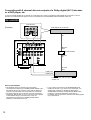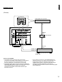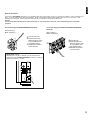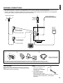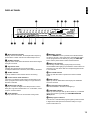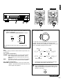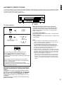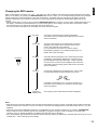
1
GB
RX-V493RDS
RX-V393RDS
Natural Sound AV Receiver
Récepteur audiovisuel “Son Naturel”
Natural Sound AV-Receiver
Natural Sound AV-receiver
Sintonizzatore AV a suono naturale
Receptor AV de Sonido Natural
Natural Sound AV Ontvanger
OWNER’S MANUAL
MODE D’EMPLOI
BEDIENUNGSANLEITUNG
BRUKSANVISNING
MANUALE DI ISTRUZIONI
MANUAL DE INSTRUCCIONES
GEBRUIKSAANWIJZING
SUPPLIED ACCESSORIES
ACCESSOIRES FOURNIS
MITGELIEFERTE ZUBEHÖRTEILE
MEDFÖLJANDE TILLBEHÖR
ACCESSORI IN DOTAZIONE
ACCESORIOS INCLUIDOS
BIJGELEVERDE ACCESSOIRES
●
●
●
●
●
●
●
●
●
●
●
●
●
●
After unpacking, check that the following parts are included.
Après le déballage, vérifier que les pièces suivantes sont incluses.
Nach dem Auspacken überprüfen, ob die folgenden Teile vorhanden sind.
Kontrollera efter det apparaten packats upp att följande delar finns med.
Verificare che tutte le parti seguenti siano contenute nell’imballaggio dell’apparecchio.
Desembalar el aparato y verificar que los siguientes accesorios están en la caja.
Controleer na het uitpakken of de volgende onderdelen voorhanden zijn.
Indoor FM Antenna
Antenne FM intérieure
UKW-Innenantenne
FM inomhusantenn
Antenna FM interna
Antena FM interior
FM Binnenantenne
●
●
●
●
●
●
●
Remote Control Transmitter
Télécommande
Fernbedienung
Fjärrkontroll
Telecomando
Transmisor de control remoto
Afstandbediening
RX-V493RDS
●
●
●
●
●
●
●
AM Loop Antenna
Cadre-antenne AM
MW-Rahmenantenne
AM ramantenn
Antenna AM ad anello
Antena de cuadro de AM
AM Lusantenne
TIME/
LEVEL
–
+
DELAY/CENTER
/REAR/SWFR TEST
PROGRAM
PROLOGIC ENHANCED
VCR
EFFECT
RX-V393RDS
– DELAY TIME +
ON/OFF
PROGRAM
TV/DBS DVD/LD
VCR
2CH
/6CH
DIR A
DIR B REC/PAUSE
PLAY
A/B
–
PRESET
+
A/B/C/D/E
DISC
PLAY
TEST
2CH
/6CH
DIR A
DIR B REC/PAUSE
PLAY
A/B
–
PRESET
CD
+
A/B/C/D/E
DISC
PLAY
PHONO
POWER
/I
●
●
●
●
●
●
●
2
75-ohm/300-ohm antenna adapter (U.K. model only)
Adaptateur d’antenne 75 ohms/300 ohms (Modèle pour le
Royaume-Uni seulement)
75 Ohm/300 Ohm Antennenstecker (nur GroßbritannienModell)
75 ohm/300 ohm antennadapter (Endast modell för
Storbritannien)
Adattatore per antenna da 75 e 300 ohm (Solo modello per
la Gran Bretagna)
Adaptador de antena de 75 ohmios/300 ohmios (Modelo
para Reino Unido sólo)
75 ohm/300 ohm antenne-adapter (Alleen modellen voor
Groot-Brittannië)
●
●
●
●
●
●
●
Batteries (size AA, R6, UM-3)
Piles (taille AA, R6, UM-3)
Batterien (Größe AA, R6, UM-3)
Batterier (storlek AA, R6, UM-3)
Batterie (dimensioni AA, R6, UM-3)
Pilas (tamaño AA, R6, UM-3)
Batterijen (maat AA, R6, UM-3)
TAPE
TUNER
CD
PHONO
VOLUME
SLEEP
ON/OFF
VIDEO
TAPE
TUNER
EFFECT
PROLOGIC ENHANCED
POWER
SLEEP
/I
VOLUME
FEATURES
English
Thank you for selecting this YAMAHA AV receiver.
● Automatic Input Balance Control for
Dolby Pro Logic Surround
● 5 Speaker Configuration
(Power Amp. Section)
RX-V493RDS
Main:
65W + 65W (8Ω) RMS Output
Power, 0.04% THD, 20–20,000 Hz
Center: 65W (8Ω) RMS Output Power,
0.04% THD, 1 kHz
Rear:
20W + 20W (8Ω) RMS Output
Power, 0.04% THD, 1 kHz
RX-V393RDS
Main:
50W + 50W (8Ω) RMS Output
Power, 0.04% THD, 20–20,000 Hz
Center: 50W (8Ω) RMS Output
Power, 0.04% THD, 1 kHz
Rear: 20W + 20W (8Ω) RMS Output
Power, 0.04% THD, 1 kHz
● Digital Sound Field Processor
● Dolby Pro Logic Surround Decoder
● Theater-like Sound Experience by the
Combination of Dolby Pro Logic and
YAMAHA DSP Technology (CINEMA DSP)
● Test Tone Generator for Easier Speaker
Balance Adjustment
● 3 Center Channel Modes
(NORMAL/WIDE/PHANTOM)
● Multi-Functions for RDS Broadcast
Reception
● 40-Station Random Access Preset Tuning
● Automatic Preset Tuning
● Preset Station Shifting Capability (Preset
Editing)
● IF Count Direct PLL Synthesizer Tuning
System
● 6-Channel Discrete Input Terminals for
Connecting with a Dolby Digital (AC-3)
Decoder
● Video Signal Input/Output Capability
● SLEEP Timer
● Remote Control Capability
CONTENTS
SUPPLIED ACCESSORIES ...........................2
BASIC OPERATIONS ...................................25
FEATURES .....................................................3
TUNING OPERATIONS ................................29
CAUTION ........................................................4
PRESET TUNING .........................................30
NOTES ABOUT THE REMOTE CONTROL
RECEIVING RDS STATIONS ........................33
TRANSMITTER ...............................................5
USING DIGITAL SOUND FIELD
PROFILE OF THIS UNIT ................................6
PROCESSOR (DSP) ....................................38
SPEAKER SETUP ..........................................7
SETTING THE SLEEP TIMER ......................42
CONNECTIONS ..............................................8
TROUBLESHOOTING ..................................43
CONTROLS AND THEIR FUNCTIONS ........16
SPECIFICATIONS .........................................44
SPEAKER BALANCE ADJUSTMENT ..........22
3
CAUTION : READ THIS BEFORE OPERATING YOUR UNIT.
1. To assure the finest performance, please read this manual
carefully. Keep it in a safe place for future reference.
2. Install this unit in a cool, dry, clean place – away from
windows, heat sources, sources of excessive vibration,
dust, moisture and cold. Avoid sources of humming
(transformers, motors). To prevent fire or electrical shock,
do not expose the unit to rain or water.
3. Never open the cabinet. If something drops into the set,
contact your dealer.
4. Do not use force on switches, controls or connection wires.
When moving the unit, first disconnect the power plug and
the wires connected to other equipment. Never pull the
wires themselves.
5. The openings on the cabinet assure proper ventilation of
the unit. If these openings are obstructed, the temperature
inside the cabinet will rise rapidly. Therefore, avoid placing
objects against these openings, and install the unit in wellventilated condition. Be sure to allow a space of at least
20 cm behind, 20 cm on the both sides and 30 cm above
the top panel of the unit. Otherwise it may not only damage
the unit, but also cause fire.
6. Always set the VOLUME control to “– ∞” before starting
the audio source play. Increase the volume gradually to an
appropriate level after playback has been started.
7. Do not attempt to clean the unit with chemical solvents;
this might damage the finish. Use a clean, dry cloth.
8. Be sure to read the “TROUBLESHOOTING” section
regarding common operating errors before concluding that
the unit is faulty.
9. When not planning to use this unit for long periods of time
(ie., vacation, etc.), disconnect the AC power plug from the
wall outlet.
10. To prevent lightning damage, disconnect the AC power
plug and antenna cable when there is an electrical storm.
11. Grounding or polarization – Precautions should be taken
so that the grounding or polarization of an appliance is not
defeated.
12.Do not connect audio equipment to the AC outlet on the
rear panel if the equipment requires more power than the
outlet is rated to provide.
This unit is not disconnected from the AC power source as
long as it is connected to the wall outlet, even if this unit
itself is turned off. This state is called the standby mode.
In this state, this unit is designed to consume a very small
quantity of power.
4
IMPORTANT
Please record the serial number of this unit in the space
below.
Model:
Serial No.:
The serial number is located on the rear of the unit.
Retain this Owner’s Manual in a safe place for future
reference.
WARNING
TO REDUCE THE RISK OF FIRE OR ELECTRIC SHOCK,
DO NOT EXPOSE THIS UNIT TO RAIN OR MOISTURE.
For U.K. customers
If the socket outlets in the home are not suitable for the plug
supplied with this appliance, it should be cut off and an
appropriate 3 pin plug fitted. For details, refer to the
instructions described below.
Note: The plug severed from the mains lead must be
destroyed, as a plug with bared flexible cord is hazardous if
engaged in a live socket outlet.
Special Instructions for U.K. Model
IMPORTANT
THE WIRES IN MAINS LEAD ARE COLOURED IN
ACCORDANCE WITH THE FOLLOWING CODE:
Blue: NEUTRAL
Brown: LIVE
As the colours of the wires in the mains lead of this
apparatus may not correspond with the coloured markings
identifying the terminals in your plug, proceed as follows:
The wire which is coloured BLUE must be connected to the
terminal which is marked with the letter N or coloured
BLACK. The wire which is coloured BROWN must be
connected to the terminal which is marked with the letter L
or coloured RED. Making sure that neither core is
connected to the earth terminal of the three pin plug.
IF THIS UNIT FAILS TO TURN ON WHEN THE
STANDBY/ON SWITCH IS PRESSED
The IMPEDANCE SELECTOR switch may not be set to
either end closely. If so, set the switch to either end closely.
English
WARNING
Do not change the IMPEDANCE SELECTOR switch
setting while the power to this unit is on, otherwise this
unit may be damaged.
IMPEDANCE SELECTOR
(Europe model)
IMPEDANCE SELECTOR
SET BEFORE POWER ON
REAR
6ΩMIN. /SPEAKER
CENTER SINGLE:6ΩMIN. /SPEAKER
DUAL:3ΩMIN. /SPEAKER
MAIN A OR B:4ΩMIN. /SPEAKER
A B:8ΩMIN. /SPEAKER
REAR
8ΩMIN. /SPEAKER
CENTER SINGLE:8ΩMIN. /SPEAKER
DUAL:4ΩMIN. /SPEAKER
MAIN A OR B:8ΩMIN. /SPEAKER
A B:16ΩMIN. /SPEAKER
NOTES ABOUT THE REMOTE CONTROL TRANSMITTER
Battery installation
Remote control transmitter operation range
RX-V493RDS
2
RX-V393RDS
l6
l6
20
20
l2
28
4
2
60
l2
28
8
40
8
4
40
2
60
0
0
–dB
–dB
1
3
Remote control
sensor
Within approximately
6 m (19.7 feet)
30°
30°
Battery replacement
If you find that the remote control transmitter must be used
closer to the main unit, the batteries are weak. Replace both
batteries with new ones.
Notes
● Use only AA, R6, UM-3 batteries for replacement.
● Be sure the polarities are correct. (See the illustration inside
the battery compartment.)
● Remove the batteries if the remote control transmitter will not
be used for an extended period of time.
● If batteries leak, dispose of them immediately. Avoid
touching the leaked material or letting it come in contact with
clothing, etc. Clean the battery compartment thoroughly
before installing new batteries.
Notes
● There should be no large obstacles between the remote
control transmitter and the main unit.
● If the remote control sensor is directly illuminated by strong
lighting (especially an inverter type of fluorescent lamp etc.),
it might cause the remote control transmitter not to work
correctly. In this case, reposition the main unit to avoid direct
lighting.
5
PROFILE OF THIS UNIT
You are the proud owner of a Yamaha stereo receiver –an extremely sophisticated audio component. The Digital Sound Field
Processor (DSP) built into this unit takes advantage of Yamaha’s undisputed leadership in the field of digital audio processing to
bring you a whole new world of listening experiences. Follow the instructions in this manual carefully when setting up your system,
and this unit will sonically transform your room into a wide range of listening environments –movie theater, concert hall, and so on.
In addition, you get incredible realism from sources encoded with Dolby Surround using the built-in Dolby Pro Logic Surround
Decoder.
Please read this operation manual carefully and store it in a safe place for later reference.
Digital Sound Field Processing
What is it that makes live music so good? Today’s advanced
sound reproduction technology lets you get extremely close to
the sound of a live performance, but chances are you’ll still
notice something missing: the acoustic environment of the live
concert hall. Extensive research into the exact nature of the
sonic reflections that create the ambience of a large hall has
made it possible for Yamaha engineers to bring you this same
sound in your own listening room, so you’ll feel all the sound of
a live concert.
Furthermore, our technicians, armed with sophisticated
measuring equipment, have even made it possible to capture
the acoustics of a variety of venues such as an actual concert
hall, theater, etc. to allow you to accurately recreate one of
several actual live performance environments, all in your own
home.
Dolby Pro Logic Surround
This unit employs a Dolby Pro Logic Surround decoder similar
to professional Dolby Stereo decoders used in many movie
theaters. By using the Dolby Pro Logic Surround decoder, you
can experience the dramatic realism and impact of Dolby
Surround movie theater sound in your own home. Dolby Pro
Logic employs a four channel five speaker system. The Pro
Logic Surround system divides the input signal into four levels:
the left and right main channels, the center channel (used for
dialog), and the rear surround sound channels (used for sound
effects, background noise, and other ambient noises). The
center channel allows listeners seated in even less-than-ideal
positions to hear the dialog originating from the action on the
screen while experiencing good stereo imaging.
Dolby Surround is encoded on the sound track of pre-recorded
video tapes, laser discs, and some TV/cable broadcasts. When
you play a source encoded with Dolby Surround on this unit,
the Dolby Pro Logic Surround decoder decodes the signal and
distributes the surround-sound effects.
This Dolby Pro Logic Surround Decoder employs a digital
signal processing system. This system improves the stability of
sound at each channel and minimizes crosstalk between
channels, so that positioning of sounds around the room is
more accurate compared with conventional analog signal
processing systems.
In addition, this unit features a built-in automatic input balance
control. This always assures you the best performance without
manual adjustment.
Manufactured under license from Dolby Laboratories Licensing
Corporation. “Dolby”, “AC-3”, “Pro Logic” and the double-D
symbol are trademarks of Dolby Laboratories Licensing
Corporation.
Dolby Pro Logic Surround + DSP
Dolby Surround sound system shows its full ability in a large
movie theater, because movie sounds are originally designed
to be reproduced in a large movie theater using many
speakers. It is difficult to create a sound environment similar to
that of a movie theater in your listening room, because the
room size, materials of inside walls, the number of speakers,
etc. of your listening room is much different from those of a
movie theater.
Yamaha DSP technology made it possible to present you with
nearly the same sound experience as that of a large movie
theater in your listening room by compensating for lack of
presence and dynamics in your listening room with its original
digital sound fields combined with Dolby Surround sound field.
6
The combination of Dolby Pro Logic Surround and DSP is used
on the sound field program “
PRO LOGIC ENHANCED”.
CINEMA DSP
The YAMAHA “CINEMA DSP” logo indicates these programs are
created by the combination of Dolby Pro Logic and YAMAHA
DSP technology.
English
SPEAKER SETUP
SPEAKERS TO BE USED
This unit is designed to provide the best sound-field quality with a 5 speaker configuration. The most effective speakers to use with
this unit are main speakers, rear speakers and a center speaker. You may omit the center speaker. (Refer to the “4-Speaker
Configuration” shown below.)
The main speakers are used for the main source sound plus the effect sounds. They will probably be the speakers from your
present stereo system. The rear speakers are used for the effect and surround sounds, and the center speaker is for the center
sounds (dialog etc.) within programs encoded with Dolby Surround. The center speaker needs to be equal in power to the main
speakers, although the rear speakers should not be equal. However, all the speakers should have high enough power handling to
accept the maximum output of this unit.
SPEAKER CONFIGURATION
5-Speaker Configuration
4-Speaker Configuration
This configuration is the most effective and recommended one.
In this configuration, the center speaker is necessary as well as
the rear speakers. If the program DOLBY PRO LOGIC or
DOLBY PRO LOGIC ENHANCED is selected, conversations
will be output from the center speaker and the ambience will be
excellent.
• Set the center channel mode to the “NORMAL” or “WIDE”
position. (For details, refer to page 23.)
The center speaker is not used in this configuration. If the
program DOLBY PRO LOGIC or DOLBY PRO LOGIC
ENHANCED is selected, the center sound is output from the
left and the right main speakers. However, the sound effect of
other programs can be the same as that of the 5-speaker
configuration.
• Be sure to set the center channel mode to the “PHANTOM”
position. (For details, refer to page 23.)
Front
Main L
Center
FrontRR
Main
Front
Main L
Dialogue
Dialogue
Surround sound
Surround sound
Rear L
Rear R
Rear L
Main
FrontRR
Rear R
SPEAKER PLACEMENT
The recommended speaker configuration, the 5-speaker configuration, will require two speaker pairs: main speakers (your normal
stereo speakers), and rear speakers, plus a center speaker. When you place these speakers, refer to the following.
Main:
In normal position. (The position of your present
stereo speaker system.)
Rear: Behind your listening position, facing slightly inward.
Nearly 1.8m (approx. 6 feet) up from the floor.
Center: Precisely between the main speakers. (To avoid
interference with TV sets, use a magnetically shielded
speaker.)
Front
R
Main R
Center
Main
FrontLL
TV set
Rear R
Rear L
7
CONNECTIONS
Never plug in this unit and other components until all connections are completed.
CONNECTIONS WITH OTHER COMPONENTS
When making connections between this unit and other components, be sure all connections are made correctly, that is to say L (left)
to L, R (right) to R, “+” to “+” and “–” to “–”. Also, refer to the owner’s manual for each component to be connected to this unit.
* If you have YAMAHA components numbered as 1, 3, 4, etc. on the rear panel, connections can be made easily by making sure
to connect the output (or input) terminals of each component to the same-numbered terminals of this unit.
RX-V493RDS
VIDEO OUT
AUDIO IN
VIDEO IN
AUDIO OUT
VIDEO OUT
VIDEO IN
2
TV/Satellite tuner
Video cassette recorder
*
AUDIO OUT
Monitor TV
GND
OUTPUT
Turntable
(Europe model)
IMPEDANCE SELECTOR
DVD/LD
TV/DBS
75Ω
UNBAL.
R SURROUND L
R MAIN L
CENTER
SUB
WOOFER
SET BEFORE POWER ON
6CH
DISCRETE
INPUT
OUTPUT
CENTER
REAR
REAR
(SURROUND)
MAIN A OR B:4ΩMIN. /SPEAKER
A B:8ΩMIN. /SPEAKER
GND
REAR
MONITOR OUT DVD/LD
IN VCR OUT
8ΩMIN. /SPEAKER
CENTER SINGLE:8ΩMIN. /SPEAKER
DUAL:4ΩMIN. /SPEAKER
VIDEO
SIGNAL
FM
ANT
6ΩMIN. /SPEAKER
CENTER SINGLE:6ΩMIN. /SPEAKER
DUAL:3ΩMIN. /SPEAKER
MAIN A OR B:8ΩMIN. /SPEAKER
A B:16ΩMIN. /SPEAKER
TV/DBS
1
*
SUB
WOOFER
GND
AM
ANT
A
PHONO
TAPE TAPE REC
/MD OUT
PB
3
DVD/LD
IN VCR OUT
TV/DBS
4
B
10dB
0dB
MAIN
**
8
: See the next page.
I00W MAX. TOTAL
SWITCHED
SPEAKERS
AUDIO OUT
VIDEO OUT
LINE IN
LINE OUT
2
,
SEE INSTRUCTION MANUAL FOR CORRECT SETTING.
AUDIO SIGNAL
Tape deck,
MD recorder, etc.
1
CD
LD player,
DVD player, etc.
AC OUTLETS
OUTPUT
1
MAIN
LEVEL
CD player
To AC outlet
English
RX-V393RDS
Monitor TV
*
AUDIO IN
VIDEO IN
VIDEO OUT
VIDEO IN
2
AUDIO OUT
Video cassette recorder
GND
OUTPUT
Turntable
(Europe model)
IMPEDANCE SELECTOR
VIDEO
75Ω
UNBAL.
R MAIN L
R SURROUND L
CENTER
SUB
WOOFER
SET BEFORE POWER ON
6CH
DISCRETE
INPUT
OUTPUT
CENTER
REAR
REAR
(SURROUND)
MAIN A OR B:4ΩMIN. /SPEAKER
A B:8ΩMIN. /SPEAKER
GND
REAR
MONITOR OUT VIDEO
8ΩMIN. /SPEAKER
CENTER SINGLE:8ΩMIN. /SPEAKER
DUAL:4ΩMIN. /SPEAKER
VIDEO
SIGNAL
FM
ANT
6ΩMIN. /SPEAKER
CENTER SINGLE:6ΩMIN. /SPEAKER
DUAL:3ΩMIN. /SPEAKER
MAIN A OR B:8ΩMIN. /SPEAKER
A B:16ΩMIN. /SPEAKER
IN VCR OUT
1
*
SUB
WOOFER
GND
AM
ANT
A
PHONO
TAPE TAPE REC
/MD OUT
PB
3
VIDEO
IN VCR OUT
4
B
10dB
0dB
MAIN
SEE INSTRUCTION MANUAL FOR CORRECT SETTING.
Tape deck,
MD recorder, etc.
I00W MAX. TOTAL
SWITCHED
SPEAKERS
AC OUTLETS
AUDIO OUT
VIDEO OUT
LINE IN
LINE OUT
CD
AUDIO SIGNAL
OUTPUT
1
MAIN
LEVEL
LD player,
DVD player, etc.
To AC outlet
CD player
1
,
2
**
1
*
: See below.
2
*
AC OUTLETS (SWITCHED)
GND terminal (For turntable use)
(Europe model) ................................. 2 SWITCHED OUTLETS
(U.K. model) ........................................ 1 SWITCHED OUTLET
Use these to connect the power cords from your components
to this unit.
The power to the SWITCHED outlets is controlled by this unit’s
STANDBY/ON switch or the provided remote control
transmitter’s POWER /I key. These outlets will supply power
to any component whenever this unit is turned on.
The maximum power (total power consumption of components)
that can be connected to the SWITCHED AC OUTLETS is 100
watts.
Connecting the ground wire of the turntable to the GND
terminal will normally minimize hum, but in some cases better
results may be obtained with the ground wire disconnected.
9
Connecting with 6 channel discrete outputs of a Dolby digital (AC-3) decoder
or a DVD player, etc.
If you have a Dolby Digital (AC-3) decoder or a DVD player etc. which incorporates a Dolby Digital (AC-3) decoder or a DTS
decoder, its 6 channel discrete outputs can be connected to the 6CH DISCRETE INPUT terminals of this unit.
RX-V493RDS
6CH DISCRETE OUTPUT
MAIN
(Example)
CENTER
SURROUND
Dolby Digital (AC-3) decoder
DIGITAL
IN
SUB
WOOFER
DVD/LD
TV/DBS
75Ω
UNBAL.
R MAIN L
R SURROUND L
CENTER
SUB
WOOFER
6CH
DISCRETE
INPUT
GND
DIGITAL
OUT
VIDEO
SIGNAL
FM
ANT
MONITOR OUT DVD/LD
IN VCR OUT
TV/DBS
RF Demodulator
GND
AM
ANT
PHONO
TAPE TAPE REC
PB
/MD OUT
3
10dB
DVD/LD
IN VCR OUT
AC-3 RF
IN
TV/DBS
4
0dB
1
MAIN
LEVEL
CD
AUDIO SIGNAL
AC-3 RF
OUT
VIDEO OUT
AUDIO OUT
Laserdisc player with AC-3 RF output or
another unit
Notes for RX-V493RDS
The laserdisc player (or another unit) must be also
connected to the DVD/LD (or TV/DBS) AUDIO SIGNAL input
terminals of this unit for playing a source with the Dolby Pro
Logic Surround decoded or in normal stereo (or monaural).
• The discrete signals input to this unit cannot be recorded by
a tape deck, MD recorder or VCR. To record a source played
on the laserdisc player (or another unit), it must be
connected to the DVD/LD (or TV/DBS) AUDIO/VIDEO
SIGNAL input terminals of this unit.
•
10
•
If you made no connection to the SUBWOOFER input
terminal of this unit or you will not use a subwoofer, you
should make a setting for distributing signals at the
SUBWOOFER channel to the right and left MAIN output
terminals on the Dolby Digital (AC-3) decoder etc.
For details, refer to the owner’s manual for the Dolby Digital
(AC-3) decoder etc.
English
RX-V393RDS
(Example)
6CH DISCRETE OUTPUT
MAIN
CENTER
SURROUND
Dolby Digital (AC-3) decoder
DIGITAL
IN
SUB
WOOFER
VIDEO
75Ω
UNBAL.
R MAIN L
R SURROUND L
CENTER
SUB
WOOFER
6CH
DISCRETE
INPUT
GND
DIGITAL
OUT
VIDEO
SIGNAL
FM
ANT
MONITOR OUT VIDEO
IN VCR OUT
RF Demodulator
GND
AM
ANT
PHONO
TAPE TAPE REC
PB
/MD OUT
3
10dB
VIDEO
AC-3 RF
IN
IN VCR OUT
4
0dB
1
MAIN
LEVEL
CD
AUDIO SIGNAL
AC-3 RF
OUT
VIDEO OUT
AUDIO OUT
Laserdisc player with AC-3 RF output or
another unit
Notes for RX-V393RDS
• The laserdisc player (or another unit) must be also
connected to the VIDEO AUDIO SIGNAL input terminals of
this unit for playing a source with the Dolby Pro Logic
Surround decoded or in normal stereo (or monaural).
• The discrete signals input to this unit cannot be recorded by
a tape deck, MD recorder or VCR. To record a source played
on the laserdisc player (or another unit), it must be
connected to the VIDEO AUDIO/VIDEO SIGNAL input
terminals of this unit.
•
If you made no connection to the SUBWOOFER input
terminal of this unit or you will not use a subwoofer, you
should make a setting for distributing signals at the
SUBWOOFER channel to the right and left MAIN output
terminals on the Dolby Digital (AC-3) decoder etc.
For details, refer to the owner’s manual for the Dolby Digital
(AC-3) decoder etc.
11
CONNECTING SPEAKERS
Subwoofer system
Rear speaker
Rear speaker
Left
Right
Center speaker
(Europe model)
IMPEDANCE SELECTOR
SET BEFORE POWER ON
OUTPUT
CENTER
REAR
REAR
6ΩMIN. /SPEAKER
CENTER SINGLE:6ΩMIN. /SPEAKER
DUAL:3ΩMIN. /SPEAKER
REAR
(SURROUND)
MAIN A OR B:4ΩMIN. /SPEAKER
A B:8ΩMIN. /SPEAKER
8ΩMIN. /SPEAKER
REAR
CENTER SINGLE:8ΩMIN. /SPEAKER
DUAL:4ΩMIN. /SPEAKER
CENTER
MAIN A OR B:8ΩMIN. /SPEAKER
A B:16ΩMIN. /SPEAKER
C
D
DUAL
SUB
WOOFER
SINGLE
Main speakers B
A
Right
Left
B
Left
Right
MAIN
CAUTION
SEE INSTRUCTION MANUAL FOR CORRECT SETTING.
SPEAKERS
Main speakers A
Note
Note on center speaker connection:
Use speakers with the specified impedance shown on the
rear of this unit.
One or two center speakers can be connected to this unit. If
you cannot place the center speaker on or under the TV, it is
recommended to use two center speakers and place them on
both sides of the TV to orient the center sound at the center
position. For connecting two center speakers, follow the
method shown below.
Note on main speaker connections:
One or two speaker systems can be connected to this unit. If
you use only one speaker system, connect it to either the
SPEAKERS A or B terminals.
Note on a subwoofer connection:
You may wish to add a subwoofer to reinforce low frequencies
or to output low bass sound from the subwoofer channel when
reproducing discrete signals.
Connect the SUBWOOFER OUTPUT terminal of this unit to
the INPUT terminal of the subwoofer amplifier, and connect the
speaker terminals of the subwoofer amplifier to the subwoofer.
With some subwoofers, including the Yamaha Active Servo
Processing Subwoofer System, the amplifier and subwoofer
are in the same unit.
REAR
CENTER
C
SINGLE
Center speaker
12
D
DUAL
Center speaker
English
How to Connect:
Connect the SPEAKERS terminals to your speakers with wire of the proper gauge, cut as short as possible. If the connections are
faulty, no sound will be heard from the speakers. Make sure that the polarity of the speaker wires is correct, that is the + and –
markings are observed. If these wires are reversed, the sound will be unnatural and lack bass.
Caution
Do not let the bare speaker wires touch each other or any metal part of this unit. This could damage this unit and/or
speakers.
For connecting to the MAIN SPEAKERS terminals
Red: positive (+)
Black: negative (–)
For connecting to the REAR and CENTER SPEAKERS
terminals
Red: positive (+)
Black: negative (–)
➀ Unscrew the knob.
➁ Insert the bare wire.
2
1
[Remove approx. 5mm
(1/4”) insulation from
the speaker wires.]
➂ Tighten the knob and
secure the wire.
3
➀ Press the tab.
➁ Insert the bare wire.
➀
➂
[Remove approx. 5mm
(1/4”) insulation from
the speaker wires.]
➂ Release the tab and
secure the wire.
➁
MAIN LEVEL switch
Normally set to “0 dB”. If desired, you can decrease the
output level at the MAIN SPEAKERS terminals by 10 dB by
setting this switch to “–10 dB”.
GND
75Ω
UNBAL.
FM
ANT
GND
AM
ANT
PHONO
TAPE
PB
3
10dB
0dB
MAIN
LEVEL
13
OUTPUT terminals (for driving speakers with external amplifiers)
SUBWOOFER OUTPUT terminal
OUTPUT
CENTER
REAR
(SURROUND)
This terminal is for connecting with the input terminal of an
amplifier for driving a subwoofer.
This terminal outputs low frequencies from the main and center
channels. (The cut-off frequency of signals output from this
terminal is 150 Hz.)
When 6 channel discrete signals are input to this unit and are
selected as the input source, this terminal outputs signals from
the subwoofer channel.
SUB
WOOFER
REAR (SURROUND) OUTPUT terminals
CENTER OUTPUT terminal
This terminal is for center channel line output. There is no
connection to this terminal when you use the built-in amplifier.
However, if you drive a center speaker with an external power
amplifier, connect the input terminal of the external amplifier to
this terminal.
These terminals are for rear channel line output. There is no
connection to these terminals when you use the built-in
amplifier.
However, if you drive rear speakers with an external stereo
power amplifier, connect the input terminals of the external
amplifier (MAIN IN or AUX terminals of a power amplifier or an
integrated amplifier) to these terminals.
Note
Output level of signals from these terminals are adjusted
by the use of VOLUME control on the front panel or VOLUME
keys on the remote control transmitter.
IMPEDANCE SELECTOR switch
Be sure to switch this only when the power to this unit is not on.
Select the position whose requirements your speaker system
meets.
WARNING
Do not change the IMPEDANCE SELECTOR switch
setting while the power to this unit is on, otherwise
this unit may be damaged.
(Upper position)
Rear:
The impedance of each speaker must be 6Ω or
higher.
Center: If you use one center speaker, the impedance of the
speaker must be 6Ω or higher.
If you use two center speakers, the impedance of
each speaker must be 3Ω or higher.
Main:
IF THIS UNIT FAILS TO TURN ON WHEN THE
STANDBY/ON SWITCH IS PRESSED
The IMPEDANCE SELECTOR switch may not be set to
either end closely. If so, set the switch to either end
closely.
If you use one pair of main speakers, the impedance
of each speaker must be 4Ω or higher.
If you use two pairs of main speakers, the impedance
of each speaker must be 8Ω or higher.
(Lower position)
IMPEDANCE SELECTOR
Rear:
SET BEFORE POWER ON
REAR
6ΩMIN. /SPEAKER
The impedance of each speaker must be 8Ω or
higher.
CENTER SINGLE:6ΩMIN. /SPEAKER
DUAL:3ΩMIN. /SPEAKER
MAIN A OR B:4ΩMIN. /SPEAKER
A B:8ΩMIN. /SPEAKER
REAR
8ΩMIN. /SPEAKER
CENTER SINGLE:8ΩMIN. /SPEAKER
DUAL:4ΩMIN. /SPEAKER
MAIN A OR B:8ΩMIN. /SPEAKER
A B:16ΩMIN. /SPEAKER
(Europe model)
14
Center: If you use one center speaker, the impedance of the
speaker must be 8Ω or higher.
If you use two center speakers, the impedance of
each speaker must be 4Ω or higher.
Main:
If you use one pair of main speakers, the impedance
of each speaker must be 8Ω or higher.
If you use two pairs of main speakers, the impedance
of each speaker must be 16Ω or higher.
English
ANTENNA CONNECTIONS
●
●
Each antenna should be connected to the designated terminals correctly, referring to the following diagram.
Both AM and FM indoor antennas are included with this unit. In general, these antennas will probably provide sufficient signal
strength. Nevertheless, a properly installed outdoor antenna will give clearer reception than an indoor one. If you experience
poor reception quality, an outdoor antenna may result in improvement.
Outdoor FM antenna
Outdoor AM antenna
Indoor FM
antenna
(included)
AM loop
antenna
(included)
75-ohm/300-ohm
antenna adapter
75Ω
UNBAL.
FM
ANT
75-ohm coaxial cable
GND
AM
ANT
75-ohm/300-ohm
antenna adapter
300-ohm feeder
Ground
Connecting the AM loop antenna
1
2
➀
➂
➁
3
Orient so that the best
reception is obtained.
* The AM loop antenna should be placed apart from the main unit. The antenna may be hung on a wall.
* The AM loop antenna should be kept connected, even if an outdoor AM antenna is connected to this unit.
GND terminal
For maximum safety and minimum interference, connect the
GND terminal to a good earth ground. A good earth ground is
a metal stake driven into moist earth.
Notes
● When connecting the indoor
FM antenna, insert its
connector into the FM ANT
terminal firmly.
● If you need an outdoor
FM antenna to improve
FM reception quality, either
300-ohm feeder or coaxial cable may be used. In locations
troubled by electrical interference, coaxial cable is
preferable.
15
CONTROLS AND THEIR FUNCTIONS
FRONT PANEL
RX-V493RDS
1
2
3
NATURAL SOUND AV RECEIVER
RX–V493RDS
4
CINEMA DSP
5
PRO LOGIC
ENHANCED
CONCERT
VIDEO
DISCO
ROCK
CONCERT
CONCERT
HALL
6 7
MONO
MOVIE
STADIUM
EFFECT
VOLUME
l6
VCR
TV/DBS
20
DVD/LD
l2
28
8
STANDBY/ON
TUNER
A/B/C/D/E
1
2
3
4
5
6
7
TAPE/MD MON
2CH/6CH
PHONO
CD
4
40
2
60
8
0
–dB
PHONES
BASS
0
l
SPEAKERS
A
2
2
3
ON
3
4
5
2
RDS MODE/FREQ EON
3
4
5
FM/AM
DOWN TUNING UP
DELAY/CENTER CENTER
/REAR/SWFR MODE
2
3
4
5
A
BALANCE
0
l
l
2
3
4
5
0
2
3
4
OFF
8 9
TREBLE
0
l
l
l
B
PTY SEEK
MEMORY
EDIT
TUNING
MODE
TIME/LEVEL
4
L5
5R
MODE
START
MAN'L/AUTO FM
AUTO/MAN'L MONO
C DEFG I J L
K
H
B
MN
RX-V393RDS
2
1
3
NATURAL SOUND AV RECEIVER
RX–V393RDS
4
7
CINEMA DSP
VOLUME
l6
TAPE/MD
MONITOR
VCR
20
VIDEO
l2
28
8
60
2
STANDBY/ON
2CH/6CH
TUNER
A/B/C/D/E
1
2
3
4
5
6
7
PHONO
CD
4
40
8
0
–dB
PHONES
BASS
0
l
l
SPEAKERS
A
B
2
2
3
ON
4
5
8 9
16
0
A
2
3
4
OFF
TREBLE
0
l
l
2
3
3
4
5
4
5
B
BALANCE
0
l
l
5
2
RDS MODE/FREQ EON
FM/AM
DOWN TUNING UP
EFFECT
CENTER
MODE
CENTER
LEVEL
REAR
LEVEL
2
3
3
4
PTY SEEK
MEMORY
EDIT
TUNING
MODE
PROGRAM
4
L5
5R
0
MODE
START
MAN'L/AUTO FM
l0
0
l0
AUTO/MAN'L MONO
C DEFG I J L O N
K6
H
P
Q
Standby mode
In this state, this unit consumes a very small quantity of
power to receive infrared-signals from the remote control
transmitter.
English
1 STANDBY/ON switch
Press this switch to turn the power to this unit on. Press it
again to turn this unit into the standby mode.
8 PHONES jack
When you listen with headphones, connect the headphones to
the PHONES jack. You can listen to the sound to be output
from the main speakers through headphones.
When listening with headphones privately, set both the
SPEAKERS A and B switches to the OFF position and switch
off the digital sound field processor (so that no DSP program
name is illuminated on the display) by pressing the EFFECT
button.
2 Remote control sensor
Receives signals from the remote control transmitter.
PHONES
3 Display panel
Shows various information. (For details, refer to page 19.)
4 Input selector buttons
Select a program source to listen to or watch. When a button is
pressed, the name of selected source appears on the display.
RX-V493RDS only
9 SPEAKERS switches
When the TV/DBS or DVD/LD input source is selected,
pressing the same button (TV/DBS or DVD/LD) switches the
input signals between 2 channel stereo signals and 6 channel
discrete signals. When switched to “6ch”, discrete signals from
the unit connected to the 6CH DISCRETE INPUT DVD/LD
TV/DBS terminals of this unit are selected as the input signals.
Set the switch A or B (or both A and B) for the main speaker
system (connected to this unit) you will use to the ON position.
Set the switch for the main speaker system you will not use to
the OFF position.
0 A/B/C/D/E button
RX-V393RDS only
Press this button to select a desired group (A–E) of preset
stations.
When the VIDEO input source is selected, pressing the same
button (VIDEO) switches the input signals between 2 channel
stereo signals and 6 channel discrete signals. When switched
to “6ch”, discrete signals from the unit connected to the 6CH
DISCRETE INPUT VIDEO terminals of this unit are selected as
the input signals.
5 DSP program selector buttons
RX-V493RDS only
Select a DSP program. When a button is pressed, the name of
selected program lights up on the display.
6 EFFECT button
Switches on/off the digital sound field processor (including the
Dolby Pro Logic Surround decoder).
7 VOLUME control
Used to raise or lower the volume level.
A Preset station number selector buttons
Select a preset station number (1 to 8).
B Tone controls
These controls are effective only for the sound from the main
speakers.
BASS
Used to increase or decrease the low frequency response.
The 0 position produces flat response.
TREBLE
Used to increase or decrease the high frequency response.
The 0 position produces flat response.
C BALANCE control
This control is effective only for the sound from the main
speakers.
Adjusts the balance of the output volume to the left and right
speakers to compensate for sound imbalance caused by
speaker location or listening room conditions.
D RDS MODE/FREQ button
When an RDS station is received, pressing this button changes
the display mode into the PS mode, PTY mode, RT mode
and/or CT mode (if the station employs those RDS data
services), and frequency display in turn.
17
E PTY SEEK MODE button
M DELAY/CENTER/REAR/SWFR and TIME/LEVEL +/–
When this button is pressed, the unit turns into the PTY SEEK
mode.
RX-V493RDS only
F PTY SEEK START button
Press this button to begin searching for a station after the
desired program type is selected in the PTY SEEK mode.
G EON button
Press this button to select a desired program type (NEWS,
INFO, AFFAIRS, SPORT) when you want to call a radio
program of that program type automatically.
H FM/AM button
Press this button to switch the reception band to FM or AM.
buttons
Adjust the delay time (DELAY), the center channel output level
(CENTER), the rear channel output level (REAR) and the
output level to the SUBWOOFER OUTPUT terminal (SWFR).
Select the item which you want to adjust by pressing the
DELAY/CENTER/REAR/SWFR button and adjust its time or
level by pressing the TIME/LEVEL +/– button.
N CENTER MODE button
Selects a center channel output mode (NORMAL, WIDE or
PHANTOM). (For details, refer to page 23.)
O PROGRAM selector button
I MEMORY (MAN’L/AUTO FM) button
RX-V393RDS only
When this button is pressed, the “MEMORY” indicator flashes
for about 5 seconds. During this period, select a desired
preset station number by pressing the corresponding preset
station number selector button to enter the displayed station
into the memory.
When this button is pressed and held for more than 3 seconds,
the automatic preset tuning begins. (For details, refer to page
31.)
When the built-in digital sound field processor (including the
Dolby Pro Logic Surround decoder) is on, this button changes
the currently selected DSP program whenever the right or left
side of this button is pressed.
J EDIT button
This button is used to exchange the places of two preset
stations with each other.
K TUNING DOWN/UP button
Used for tuning. Press the “UP” side to tune in to higher
frequencies, and press the “DOWN” side to tune in to lower
frequencies.
When this unit is in the PTY SEEK mode, pressing this switch
changes the currently selected program type.
L TUNING MODE (AUTO/MAN’L MONO) button
Press this button to switch the tuning mode to automatic or
manual. To select the automatic tuning mode, press this
button so that the “AUTO” indicator lights up on the display. To
select the manual tuning mode, press this button so that the
“AUTO” indicator goes off.
18
P CENTER LEVEL control
RX-V393RDS only
Adjusts the sound output level of the center speaker.
Q REAR LEVEL control
RX-V393RDS only
Adjusts the sound output level of the rear speakers.
English
DISPLAY PANEL
1
2 3 4
PRESET
5 6
SLEEP
ms dB STEREO
NORM
WIDE
PHANTOM
l00
0 20
MHz
EFFECT OFF
PRO LOGIC CONCERT MONO DISCO ROCK CONCERT
ENHANCED VIDEO MOVIE STADIUM CONCERT HALL
kHz
MEMORY AUTO PTY HOLD NEWS INFO
PS
7 8
PTY
9
RT
CT EON AFFAIRS SPORT
TAPE MON
0A B
D
C
1 Multi-information display
Displays various information, for example station frequency,
preset station number and name of selected input source.
2 STEREO indicator
Lights up when an FM stereo broadcast with sufficient signal
strength is received.
3 Signal-level meter
Indicates the signal level of the received station.
If multipath interference is detected, the indication decreases.
8 MEMORY indicator
When the MEMORY button is pressed, this indicator flashes
for about 5 seconds. During this period, the displayed station
can be programmed to the memory by using the A/B/C/D/E
button and the preset station number selector buttons.
9 RDS mode indicators
The name(s) of RDS mode(s) employed by the currently
received RDS station light(s) up. Illumination of the indicator on
the head of a name shows that the corresponding RDS mode
is now selected.
4 SLEEP indicator
Lights up while the built-in SLEEP timer is functioning.
0 PTY HOLD indicator
5 Center channel mode indicators
The name of a selected center channel mode lights up only
when a program which uses the Dolby Pro Logic Surround
decoder is selected.
A EON indicator
6 EFFECT OFF indicator
Lights up if neither the digital sound field processor nor the
Dolby Pro Logic Surround decoder is on. In this state, sound
output is 2-channel stereo.
7 AUTO indicator
Lights up when this unit is in the automatic tuning mode.
Lights up while the search is performed in the PTY SEEK
mode.
Lights up when an RDS station that employs the EON data
service is received.
B Program type name indicators
The name selected in the EON mode lights up.
C TAPE MON indicator
Lights up when the tape deck (or MD recorder etc.) is selected
as the input source by pressing the TAPE/MD MONITOR
(MON) button.
D DSP program indicators
The name of a selected DSP program lights up when the builtin digital sound field processor and/or the Dolby Pro Logic
Surround decoder is on.
19
REMOTE CONTROL TRANSMITTER
The remote control transmitter provided with this unit is designed to control all the most commonly used functions of this unit. If the
CD player and tape deck connected to this unit are YAMAHA components designed for remote control compatibility, then this
remote control transmitter will also control various functions of each component.
RX-V393RDS
RX-V493RDS
9
1
TIME/
LEVEL
–
DELAY/CENTER
+ /REAR/SWFR TEST
PROGRAM
PROLOGIC ENHANCED
VCR
EFFECT
ON/OFF
8
7
9
1
– DELAY TIME +
PROGRAM
TV/DBS DVD/LD
TEST
PROLOGIC ENHANCED
VCR
DIR B REC/PAUSE
1
2
–
PRESET
+
A/B/C/D/E
DISC
PLAY
2
4
20
/I
DIR B REC/PAUSE
1
TAPE
6
2
PLAY
A/B
–
PRESET
+
A/B/C/D/E
DISC
CD
PLAY
2
PHONO
POWER
3
DIR A
TUNER
8
7
2CH
/6CH
PLAY
A/B
ON/OFF
VIDEO
2CH
/6CH
DIR A
EFFECT
POWER
3
5
4
TUNER
6
CD
PHONO
VOLUME
SLEEP
TAPE
/I
VOLUME
SLEEP
5
1 DELAY/CENTER/REAR/SWFR and TIME/LEVEL +/–
keys
RX-V493RDS only
Adjust the delay time (DELAY), the center channel output level
(CENTER), the rear channel output level (REAR) and the
output level to the SUBWOOFER OUTPUT terminal (SWFR).
Select the item which you want to adjust by pressing the
DELAY/CENTER/REAR/SWFR key and adjust its time or level
by pressing the TIME/LEVEL +/– key.
(For details, refer to page 28, 40 and 41.)
DELAY TIME +/– key
RX-V393RDS only
7 Program selector keys
PROGRAM:
When the built-in digital sound field processor (including the
Dolby Pro Logic Surround decoder) is on, this key changes the
currently selected DSP program whenever the right or left side
of this key is pressed.
PROLOGIC:
Directly selects the
PRO LOGIC program.
ENHANCED:
Directly selects the
PRO LOGIC ENHANCED program.
8 EFFECT ON/OFF key
Switches on/off the digital sound field processor (including the
Dolby Pro Logic Surround decoder).
Adjusts the delay time, or the time difference between the
begining of source sound and the begining of effect sound.
(For details, refer to page 41.)
9 TEST key
2 Tuner keys
Used for speaker balance adjustment. (For details, refer to
page 22–24.)
Control tuner.
+: Selects higher preset station number.
–: Selects lower preset station number.
A/B/C/D/E: Selects the group (A – E) of preset station
numbers.
3 SLEEP timer key
This key is used to turn the built-in SLEEP timer on and off,
and to set the SLEEP time. (For details, refer to page 42.)
4 POWER /I key
Turns the power to this unit on and turns this unit into the
standby mode alternately.
5 VOLUME +/– keys
Turn the volume level up/down.
English
For Control of This Unit
For Other Component Control
Identify the remote control transmitter keys with your
component’s keys. If these keys are identical, their functions
will be the same. On each key function, refer to the
corresponding instruction on your component’s manual.
1 Tape deck keys
Control tape deck.
* DIR A, B and A/B are applicable only to double
cassette tape deck.
* For a single cassette deck with automatic reverse
function, pressing DIR A will reverse the direction of
tape running.
6 Input selector keys
Select input source.
2 CD player keys
RX-V493RDS only
Control compact disc player.
* DISC is applicable only to compact disc changer.
When the TV/DBS or DVD/LD input source is selected,
pressing the same key (TV/DBS or DVD/LD) switches the input
signals between 2 channel stereo signals and 6 channel
discrete signals. When switched to “6ch”, discrete signals from
the unit connected to the 6CH DISCRETE INPUT DVD/LD
TV/DBS terminals of this unit are selected as the input signals.
RX-V393RDS only
When the VIDEO input source is selected, pressing the same
key (VIDEO) switches the input signals between 2 channel
stereo signals and 6 channel discrete signals. When switched
to “6ch”, discrete signals from the unit connected to the 6CH
DISCRETE INPUT VIDEO terminals of this unit are selected as
the input signals.
21
SPEAKER BALANCE ADJUSTMENT
This procedure lets you adjust the sound output level balance between the main, center, and rear speakers using the built-in test
tone generator. When this adjustment is performed, the sound output level heard at the listening position will be the same from
each speaker. This is important for the best performance of the digital sound field processor and the Dolby Pro Logic Surround
decoder.
RX-V493RDS
1
2
5
TIME/
LEVEL
–
l2
28
+
DELAY/CENTER
/REAR/SWFR TEST
PROGRAM
l6
20
RX-V393RDS
PROLOGIC ENHANCED
5
– DELAY TIME +
EFFECT
ON/OFF
PROGRAM
TEST
EFFECT
PROLOGIC ENHANCED
ON/OFF
8
VCR
TV/DBS DVD/LD
4
40
VCR
VIDEO
2CH
/6CH
2CH
/6CH
2
60
0
DIR A
DIR B REC/PAUSE
–
+
PLAY
DIR A
DIR B REC/PAUSE
–
+
PLAY
–dB
A/B
PRESET
A/B/C/D/E
DISC
3
TAPE
A/B
TUNER
PLAY
PRESET
CD
A/B/C/D/E
DISC
PLAY
PHONO
4
POWER
/I
3
VOLUME
l6
20
CD
PHONO
VOLUME
POWER
SLEEP
1
TAPE
TUNER
/I
VOLUME
SLEEP
Select the main speakers to be used.
l2
SPEAKERS
28
8
A
B
4
40
ON
OFF
2
60
0
–dB
Set to the “∞” position.
2
* If you use two main speaker systems, press both the A
and B switches.
4
Turn the power on.
BASS
0
l
TREBLE
0
l
l
l
2
2
3
3
4
4
5
STANDBY/ON
5
2
BALANCE
0
l
l
2
3
3
4
4
5
5
2
2
3
3
4
4
L5
Set to the “0” position.
5
22
TEST
5R
TIME/
LEVEL
–
+
DELAY/CENTER
/REAR/SWFR TEST
PROGRAM
PROLOGIC ENHANCED
VCR
EFFECT
– DELAY TIME +
ON/OFF
PROGRAM
TEST
2CH
/6CH
8
DIR A
DIR B REC/PAUSE
–
+
ON/OFF
VIDEO
2CH
/6CH
l2
EFFECT
PROLOGIC ENHANCED
VCR
TV/DBS DVD/LD
l6
20
28
RX-V393RDS
English
RX-V493RDS
PLAY
DIR A
DIR B REC/PAUSE
–
+
PLAY
4
40
2
60
TAPE
A/B
A/B
TAPE
0
–dB
PRESET
A/B/C/D/E
TUNER
PLAY
DISC
PRESET
A/B/C/D/E
DISC
CD
PLAY
6
8
/I
POWER
VOLUME
/I
7
6
Select the center channel output mode suitable for your
speaker configuration.
(Refer to “SPEAKER CONFIGURATION” on page 7.)
7
7
Turn up the volume.
VOLUME
l6
20
l2
28
CENTER
MODE
VOLUME
SLEEP
SLEEP
7
CD
PHONO
PHONO
POWER
TUNER
NORMAL
8
4
40
2
60
WIDE
0
–dB
PHANTOM
On the feature of each mode, refer to the “Note” shown
below.
You will hear a test tone (like pink noise) from the left main
speaker, then the center speaker, then the right main
speaker, and then the rear speakers, for about two seconds
each. The display changes as shown below.
Center
Main (L)
Note
In step 6, when you select a center channel output mode, note
the following.
For 5 speaker configuration)
NORMAL: Select this mode when you use a center speaker
that is smaller than the main speakers. In this
mode, the bass tone will be output from the main
speakers.
WIDE:
Select this mode when you use the center speaker
approximately same sized as the main speakers.
For 4 speaker configuration)
PHANTOM: Select this mode when you do not use the center
speaker. The center sound will be output from the
left and right main speakers.
Rear (L and R)
*
8
Main (R)
The test tone from the left rear speaker and the right
rear speaker will be heard at the same time.
Adjust the BALANCE control so that the effect sound
output level of the left main speaker and the right main
speaker are the same.
BALANCE
0
l
l
2
2
3
3
4
4
L5
5R
CONTINUED
23
RX-V493RDS
9
RX-V393RDS
10
10
TIME/
LEVEL
–
+
DELAY/CENTER
/REAR/SWFR TEST
PROGRAM
PROLOGIC ENHANCED
– DELAY TIME +
EFFECT
ON/OFF
PROGRAM
TEST
EFFECT
ON/OFF
PROLOGIC ENHANCED
l6
VCR
TV/DBS DVD/LD
20
2CH
/6CH
DIR A
A/B
–
PRESET
+
A/B/C/D/E
8
60
2
VIDEO
2CH
/6CH
4
DIR A
DIR B REC/PAUSE
–
+
0
TAPE
PLAY
A/B
–dB
TUNER
PLAY
DISC
28
40
PLAY
DIR B REC/PAUSE
VCR
l2
PRESET
A/B/C/D/E
DISC
CD
PLAY
/I
VOLUME
9
SLEEP
9
Adjust the sound output levels of the center speaker and
the rear speakers so that they become almost as same
as that of the main speakers.
10
Press once or more so that “CENTER” or “REAR”
appears on the display.
* Select “CENTER” to adjust the output level of the
center speaker, and select “REAR” to adjust the
output level of the rear speakers.
DELAY/CENTER
/REAR/SWFR
b)
Adjust its level.
* Pressing the + side raises and the – side lowers the
level.
TIME/
–
LEVEL
+
0
24
l0
/I
VOLUME
TEST
Disappears.
Notes
Once you have completed these adjustments, you can
adjust whole sound level on your audio system by using
the VOLUME control (or the VOLUME keys on the remote
control transmitter) only.
● If you use external power amplifiers, you may also use
their volume controls to achieve proper balance.
● If there is insufficient sound output from the center and
rear speakers, you may decrease the main speaker
output level by setting the MAIN LEVEL switch on the
rear panel to “–10 dB”.
●
●
RX-V493RDS only
In step 9, if the center channel mode is in the
“PHANTOM” position, the sound output level of the center
speaker cannot be adjusted. This is because in this
mode, the center sound is automatically output from the
left and right main speakers.
RX-V393RDS
CENTER
LEVEL
POWER
SLEEP
Cancel the test tone.
RX-V493RDS
Make the adjustment of each speaker output level at your
listening position with the remote control transmitter.
a)
CD
PHONO
PHONO
POWER
TAPE
TUNER
REAR
LEVEL
0
l0
BASIC OPERATIONS
English
From page 25 to 41, this manual describes how to operate this unit mainly by using the front panel control parts.
To operate this unit on the remote control transmitter, use the corresponding keys on the remote control transmitter.
TO PLAY A SOURCE
3
2
1, 6
l6
20
l2
28
8
4
40
2
60
0
–dB
4
1
7
5
VOLUME
l6
20
l2
28
8
6
4
40
Play the source. (For detailed information on the
tuning operation, refer to page 29.)
VOLUME
l6
20
l2
28
2
60
8
0
4
40
–dB
Set to the “∞” position.
2
60
0
–dB
2
Adjust to the desired output level.
Turn the power on.
STANDBY/ON
7
3
Select the desired input source by using the input
selector buttons.
(For video sources, turn the TV/monitor ON.)
TUNER
PHONO
CD
* The name of the selected input source will appear on
the display.
4
Select the main speakers to be used.
SPEAKERS
A
ON
B
If desired, adjust the BASS, TREBLE and BALANCE
controls (refer to page 28), and use the digital sound
field processor. (Refer to page 39.)
Notes on using the input selector buttons
Note that pressing on each input selector button selects
the source which is connected to the corresponding input
terminals on the rear panel.
● The selection of TAPE/MD MONITOR (MON) cannot be
canceled by pressing another input selector button. To
cancel it, press TAPE/MD MONITOR (MON) again so that
the “TAPE MON” indicator disappears from the display.
When you select a button other than TAPE/MD
MONITOR (MON), make sure that the “TAPE MON”
indicator is not illuminated on the display.
● If you select the input selector button for a video source
without canceling the selection of TAPE/MD MONITOR
(MON), the playback result will be the video image from
the video source and the sound from the audio tape (or
MD etc.).
● Once you play a video source, its video image will not be
interrupted even if the input selector button for an audio
source is selected.
●
OFF
* If you use two main speaker systems, press both the A
and B switches.
When you finish using this unit
Press the STANDBY/ON switch on the front panel again or
the POWER /I key on the remote control transmitter to turn
this unit into the standby mode.
25
To listen to a decoded source using Dolby Digital (AC-3) or DTS by reproducing the signals
input to the 6CH DISCRETE INPUT terminals of this unit.
In step 3, press the button (shown below) once or more so that
“6ch” appears on the display.
Discrete signals from the unit connected to the 6CH
DISCRETE INPUT terminals of this unit are selected as the
input signals.
RX-V493RDS
TV/DBS
DVD/LD
TAPE/MD MON
2CH/6CH
TV/DBS
DVD/LD
TAPE/MD MON
2CH/6CH
or
To cancel listening to a decoded source using Dolby
Digital (AC-3) or DTS
Press the same button again or select another input source.
Note for reproducing discrete signals with Dolby Digital
(AC-3) or DTS decoded:
1. Your speaker system must include a center speaker.
2. Your speaker system must include a subwoofer.
* Connect a subwoofer which has a built-in amplifier to the
SUBWOOFER OUTPUT terminal of this unit.
* You can do without using a subwoofer. If you do so, you
should make a setting for distributing signals at the LFE
channel to the right and left MAIN output terminals on the
Dolby Digital (AC-3) Decoder etc.
For details, refer to the owner’s manual for the Dolby
Digital (AC-3) Decoder etc.
Notes
● When you switch to the “6ch” mode, the built-in Digital
Sound Field processor will not work and adjustment of delay
time cannot be made.
●
RX-V393RDS
VCR
VIDEO
2CH/6CH
26
Switching this unit to the “6ch” mode will input no signal to
this unit if there is no connection to the 6CH DISCRETE
INPUT terminals of this unit.
English
TO RECORD A SOURCE TO TAPE (OR MD)
RX-V493RDS
RX-V393RDS
1 4
2
4
1 2
l6
20
l6
l2
28
20
8
8
4
40
2
60
l2
28
4
40
2
60
0
0
–dB
1
3
Select the source to be recorded.
TUNER
2
–dB
PHONO
CD
4
Begin recording on the tape deck (or MD recorder etc.)
or VCR connected to this unit.
If the tape deck (or MD recorder etc.) is used for
recording, you can monitor the sounds being recorded
by pressing TAPE/MD MONITOR (MON) so that the
“TAPE MON” indicator lights up on the display.
RX-V493RDS
Play the source and then turn the VOLUME control up
to confirm the input source. (For detailed information
on the tuning operations, refer to the page 29.)
RX-V393RDS
TV/DBS
DVD/LD
TAPE/MD MON
2CH/6CH
PHONO
CD
TAPE/MD
MONITOR
VCR
TUNER
PHONO
VOLUME
l6
20
l2
28
8
4
40
2
60
0
–dB
Notes
The settings of DSP and the VOLUME, BASS, TREBLE
and BALANCE controls have no effect on the material
being recorded.
● In step 1, do not make an input source selection so that
“6ch” appears on the display. Signals input to this unit’s
6CH DISCRETE INPUT terminals cannot be recorded by a
tape deck, MD recorder or VCR.
●
27
Selecting the SPEAKER system
Because one or two speaker systems (as main speakers) can
be connected to this unit, the SPEAKERS switches allow you
to select speaker system A or B, or both at once.
Adjusting the BASS and TREBLE
controls
BASS
0
l
TREBLE
0
l
l
l
2
SPEAKERS
2
3
A
3
4
4
5
ON
2
2
3
3
B
5
4
4
5
5
OFF
BASS
Adjusting the BALANCE control
Adjust the balance of the output volume to the left and right
speakers to compensate for sound imbalance caused by
speaker location or listening room conditions.
BALANCE
0
l
l
2
: Turn this clockwise to increase (or counterclockwise to decrease) the low frequency
response.
TREBLE : Turn this clockwise to increase (or counterclockwise to decrease) the high frequency
response.
Note
These controls are effective only for the sound from the main
speakers.
2
3
3
4
4
L5
5R
Note
This control is effective only for the sound from the main
speakers.
onlyonly
RX-V493RDS
Adjusting the subwoofer output level RX-V493
If your audio system includes a subwoofer, and an amplifier driving the subwoofer (or a subwoofer system including an amplifier) is
connected to the SUBWOOFER OUTPUT terminal on the rear of this unit, you can adjust the subwoofer output level on this unit.
1
Press once or more so that “SWFR” appears on the
display.
DELAY/CENTER
/REAR/SWFR
2
By continuously pressing the “+” or “–” side of the
TIME/LEVEL button, the level value changes continuously.
If you feel that bass tone is insufficient, increase the level,
and if you feel that bass tone is overly emphasized,
decrease the level.
TIME/LEVEL
Adjustable
Control range: MIN, –20 to 0 dB
28
Normally, if station signals are strong and there is no interference, quick automatic-search tuning (AUTOMATIC TUNING) is
possible. However, if signals of the station you want to select are weak, you must tune to it manually (MANUAL TUNING).
English
TUNING OPERATIONS
l6
20
l2
28
8
4
40
2
60
0
–dB
1 2
AUTOMATIC TUNING
1
2
MANUAL TUNING
1
Select “TUNER” as the input source.
TUNER
PHONO
4 3
Select “TUNER” as the input source.
CD
TUNER
Select the reception band (FM or AM) confirming it on
the display.
2
FM/AM
PHONO
CD
Select the reception band (FM or AM) confirming it on
the display.
FM/AM
or
3
3
TUNING
MODE
AUTO/MAN’L MONO
4
or
Turn the “AUTO”
indicator off.
AUTO/MAN’L MONO
AUTO
To tune to a higher frequency, press the right side
once.
To tune to a lower frequency, press the left side once.
TUNING
MODE
4
Tune to a desired station manually.
DOWN TUNING UP
DOWN TUNING UP
* If the station where tuning search stops is not the desired
one, press again.
* If the tuning search does not stop at the desired station
(because the signals of the station are weak), change to
the MANUAL TUNING method.
* To continue tuning search, press and hold the button.
Notes
• If you tune to an FM station manually, it is received in
monaural mode automatically to increase the signal quality.
• When tuned in to a station, the frequency of the received
station is shown on the display. If an RDS station that
employs PS data service is received, the frequency is then
replaced by the station name. Refer to page 35 for details.
29
PRESET TUNING
MANUAL PRESET TUNING
This unit can store station frequencies selected by tuning operation. With this function, you can recall any desired station by only
selecting the preset station number where it is stored. Up to 40 stations (8 stations x 5 groups) can be stored.
l6
20
l2
28
8
4
40
2
60
0
–dB
2, 1 4, 2
To recall a preset station
To store stations
1
2
3
1
Tune to a desired station.
(Refer to the previous page for tuning procedure.)
Select the group of preset stations.
A/B/C/D/E
Select a desired group (A – E) of preset stations
confirming it on the display.
A/B/C/D/E
2
PRESET
Select the preset station number.
1
3
2
3
4
5
6
7
8
MEMORY
MEMORY
MAN’L/AUTO FM
Flashes on and off
for about 5 seconds.
4
Select a preset station number where you want to
program the station before the “MEMORY” indicator
goes off from the display.
1
2
3
4
5
6
7
8
Memory back-up
The memory back-up circuit prevents the programmed data
from being lost even if this unit is turned into the standby
mode or the power plug is disconnected from the AC outlet or
the power is cut due to temporary power failure. If, however,
the power is cut for more than one week, the memory may be
erased. If so, it can be re-programmed by simply following
the PRESET TUNING steps.
STEREO
PRESET
MHz
AUTO
0 20
l00
CONCERT HALL
Shows the displayed station has been
programmed to A1.
* In the same way, program other stations to A2, A3 ... A8.
* You can program more stations to preset station numbers
on other groups in the same way by selecting other groups
in step 2.
30
Notes
A new setting can be programmed in place of the former
one.
• For presets, the setting of the reception mode (stereo or
monaural) is stored along with the station frequency.
•
You can also make use of an automatic preset tuning function for RDS stations only. By this function, this unit performs automatic
tuning and stores RDS stations with strong signals sequentially. Up to 40 stations are stored automatically in the same way as in
the manual preset tuning method on page 30.
* Refer to page 33–37 for details on RDS stations.
English
AUTOMATIC PRESET TUNING
l6
20
l2
28
8
4
40
2
60
0
–dB
1 23
To store stations
1
When the automatic preset tuning is finished
The display shows the frequency of the last preset station.
Check the contents and the number of preset stations by
following the procedure of the section “To recall a preset
station” on page 30.
FM/AM
To recall a preset station
2
MEMORY
MAN’L/AUTO FM
PRESET
Press and hold for more
than 3 seconds.
MEMORY AUTO
Flashes.
3
DOWN TUNING UP
To tune to higher frequencies, press right side once.
To tune to lower frequencies, press left side once.
* If the TUNING button is not pressed, in a while, the
automatic preset tuning begins automatically toward higher
frequencies.
Simply follow the procedure of the section “To recall a preset
station” on page 30.
* A recalled station is shown by the frequency or station name
on the display.
Notes
● You can replace a preset station by another FM or AM
station manually by simply following the procedure of the
section “To store stations” on page 30.
● The automatic preset tuning search will be performed
through all RDS network frequencies until stations are
stored up to E8. If the number of received stations is not
enough to be stored up to E8, the search is finished
automatically after searching all frequencies.
● With this function, only RDS stations with sufficient signal
strength are stored automatically. If the station you want to
program is weak in signal strength, tune to it in monaural
manually and program it by following the procedure of the
section “To store stations” on page 30.
* There may be a case that this function cannot receive a
station which could be received by the automatic tuning
method. This is because this function receives a large
volume of PI (Program Identification) data along with the
station.
The automatic preset tuning begins from the frequency
currently displayed. Received stations are programmed to
A1, A2 ... A8 sequentially.
* If more than 8 stations are received, they are also
programmed to the preset station numbers on other groups
(B, C, D and E) in that order.
If you want to store the first station received by the
automatic preset tuning to a desired preset station
number.
If, for example, you want to store the first received station to
C5, select “C5” by using the A/B/C/D/E button and the preset
station number selector buttons after pressing the MEMORY
button in step 2. Then press the TUNING button. The first
received station is stored to C5, and next stations to C6, C7 ...
sequentially.
If stations are stored up to E8, the automatic preset tuning is
finished automatically.
31
EXCHANGING PRESET STATIONS
You can exchange the places of two preset stations with each other as shown below.
l6
20
l2
28
8
4
40
2
60
0
–dB
2, 4
Example)
If you want to shift the preset station on E1 to A5, and vice
versa.
1
Recall the preset station on E1 (by following the method
of “To recall a preset station” on page 30).
4
EDIT
2
EDIT
PRESET
MEMORY
Flashes.
3
Next, recall the preset station on A5 by following the
same method with step 1.
PRESET
MEMORY
Shows the exchange of stations is completed.
Flashes.
32
RECEIVING RDS STATIONS
English
In areas where RDS broadcasts cannot be received, the RDS broadcast functions do not operate. (The procedures from page 33 to
page 37 are not necessary.)
RDS (Radio Data System) is a data transmission system gradually being introduced by FM stations in many countries. Stations
using this system transmit an inaudible stream of data in addition to the normal radio signal.
RDS data contains various information, such as PI (Program Identification), PS (Program Service name), PTY (Program Type), RT
(Radio Text), CT (Clock Time), EON (Enhanced Other Networks), etc.
RDS function is carried out among the network stations.
* This unit utilizes PI, PS, PTY, RT, CT and EON to receive RDS broadcast stations.
Displaying RDS data
PRESET
MEMORY AUTO PTY HOLD NEWS INFO
PS
PTY
RT
CT EON AFFAIRS SPORT
TAPE MON
SLEEP NORM
ms dB STEREO
WIDE
kHz
PHANTOM
l00
0 20
MHz
EFFECT OFF
PRO LOGIC CONCERT MONO DISCO ROCK CONCERT
ENHANCED VIDEO MOVIE STADIUM CONCERT HALL
This unit can be turned into the following five modes to display
RDS data.
PS (Program Service name) mode:
CT (Clock Time) mode:
Displays the name of the RDS station now being received
instead of the frequency.
Displays current time. This signal comes from the RDS station
now being received.
PTY (Program Type) mode:
EON (Enhanced Other Networks)
mode:
Displays the type of the program on the RDS station now being
received. There are 15 program types to classify RDS
stations. Refer to the next page for details.
RT (Radio Text) mode:
Automatically receives a program of the designated program
type when its broadcast starts, in place of the program now
being received. When the broadcast of the called program
ends, the previously received program (or another program on
the same station) is recalled.
Displays information about the program (such as title of the
song, name of the singer, etc.) on the RDS station now being
received.
33
Program types in the PTY mode
NEWS
News:
Short accounts of facts, events and publicly
expressed views, reportage and actuality.
AFFAIRS
Current affairs:
Topical program expanding or enlarging
upon the news, generally in different
presentation style or concept, including
documentary debate, or analysis.
INFO
Information:
Program whose purpose is to impart advice
in the widest sense, including meteorological
reports and forecasts, consumer affairs,
medical help, etc.
SPORT
Sport:
Program concerned with any aspect of sport.
EDUCATE
Education:
Program intended primarily to educate, of
which the formal element is fundamental.
DRAMA
Drama:
All radio plays and serials.
CULTURE
Culture:
Programs concerned with any aspect of
national or regional culture, including
religious affairs, philosophy, social science,
language, theatre, etc.
SCIENCE
Science:
Programs about the natural sciences and
technology.
34
VARIED
Varied:
Used for mainly speech-based programs
usually of light-entertainment nature, not
covered by above categories. Examples are:
quizzes, panel games, personality interviews,
comedy and satire.
POP M
Pop:
Commercial music, which would generally be
considered to be of current popular appeal,
often featuring in current or recent record
sales charts.
ROCK M
Rock:
Contemporary modern music, usually written
and performed by young musicians.
M.O.R. M
M.O.R.:
(Middle of the Road Music). Common term to
describe music considered to be “easylistening”, as opposed to Pop, Rock or
Classical. Music in this category is often but
not always, vocal, and usually of short
duration (<5 min.)
LIGHT M
Light classics:
Classical Musical for general, rather than
specialist appreciation. Examples of music in
this category are instrumental music, and
vocal or choral works.
CLASSICS
Serious classics:
Performances of major orchestral works,
symphonies, chamber music etc., and
including Grand Opera.
OTHER M
Other music:
Musical styles not fitting into any of the above
categories. Particularly used for specialist
music, of which Jazz, Rhythm & Blues, Folk,
Country, and Reggae are examples.
English
Changing the RDS modes
When an RDS station is received, “PS”, “PTY”, “RT” and/or “CT” that correspond to the RDS data services employed by the station
light up on the display. By pressing the RDS MODE/FREQ button once or more, you can change the display mode among the RDS
modes employed by the received station in the order shown below. (The RDS mode not employed by the station cannot be
selected.) Illumination of the indicator on the head of a name of RDS mode shows that the corresponding RDS mode is now
selected.
* When an RDS station is received, do not press the RDS MODE/FREQ button until one or some names of RDS modes light up on
the display. If the button is pressed before one or some names light up on the display, the mode cannot be changed. This is
because the unit has not received all of the RDS data on the station yet.
* If no name of RDS mode lights up on the display, the mode cannot be changed.
PS mode
The name of the station being received is displayed.
If the station does not employ the PS data service, this mode
will not be selected.
PTY mode
The type of the program on the station being received is
displayed. If the station does not employ the PTY data
service, this mode will not be selected.
(You can make this unit search for a station which is
broadcasting a program of your desired program type. For
details, refer to the next page.)
RT mode
Information about the program on the station being received
is displayed. Information is displayed by a maximum of 64
Roman Alphabets including umlaut sign. If other characters
are used on the RT data, they are displayed with under-bars.
If the station does not employ the RT data service, this mode
will not be selected.
CT mode
Current time is displayed in the following form. The CT data
from the station being received changes every minute.
RDS MODE/FREQ
Hour
Minute
If the data is accidentally cut off, “CT WAIT” may light up. If
the station does not employ the CT data service, this mode
will not be selected.
Frequency
display mode
The frequency of the station being received is displayed.
Notes
• RDS data service cannot be utilized by this unit if the received signal is not strong enough. Especially, the RT (Radio Text mode)
needs much data to be received, so it may occur that RT mode cannot be displayed even if other RDS modes (PS, PTY, etc.) are
displayed.
• There may be a case that RDS data reception is not possible due to poor reception conditions. If so, press the TUNING MODE
button so that the “AUTO” indicator goes off from the display. Though the reception mode is changed to monaural by this
operation, when you change the display to an RDS mode, RDS data may be displayed.
• If the signal strength gets weakened by external interference during receiving an RDS station, the RDS data service may be cut off
suddenly and “...WAIT” will light up on the display.
35
Calling a program of your desired program type
from among preset RDS stations (PTY SEEK)
By designating a program type, the unit automatically searches all preset stations for an RDS station which broadcasts a program of
that program type.
* There are 15 program types to classify RDS stations. For details, refer to page 34.
2
l6
20
l2
28
8
4
40
2
60
0
–dB
1 3
1
Turn the unit into the PTY SEEK mode.
3
Begin searching all preset RDS stations.
PTY SEEK
MODE
START
PTY SEEK
MODE
START
Flashes.
* The program type of the station now being received or
“NEWS” flashes on the display.
AUTO PTY HOLD
PS
2
PTY RT CT
Flashes.
Select the desired program type.
* The “PTY HOLD” indicator lights up on the display.
DOWN TUNING UP
•
•
•
If a station which broadcasts a program of the program
type is found, the unit stops at the station and the
program type lights up.
If the called station is not the desired one, press the PTY
SEEK START button once more.
The unit begins searching for another station which
brodcasts a program of the same program type.
To stop the search, press the PTY SEEK START button
once more.
To cancel this function
If the PTY SEEK MODE button is pressed once more, the
PTY SEEK mode is canceled.
36
English
Making this unit call a program of your desired program type automatically
when its broadcast starts
This function uses the EON (Enhanced Other Networks) data service on the RDS station network.
By only selecting a desired program type (NEWS, INFO, AFFAIRS or SPORT), this unit automatically searches all preset RDS
stations for a station that broadcasts a program of that program type in the background, and, if found, receives a program when its
broadcast starts in place of the program now being received.
* This function can be used only when an RDS station that employs the EON data service is received. (When such a station is
received, the “EON” indicator lights up on the display.)
l6
20
l2
28
8
4
40
2
60
0
–dB
2
1
Make sure that the “EON” indicator is illuminated on the
display.
MEMORY AUTO PTY HOLD NEWS INFO
PS
PTY
RT
TAPE MON
CT EON AFFAIRS SPORT
3
When the broadcast of the called program ends, the
previously received program (or another program on
the same station) is recalled.
SLEEP NORM
ms dB STEREO
WIDE
kHz
PHANTOM
l00
0 20
MHz
EFFECT OFF
PRO LOGIC CONCERT MONO DISCO ROCK CONCERT
ENHANCED VIDEO MOVIE STADIUM CONCERT HALL
PS
* If the “EON” indicator is not illuminated on the display,
receive an (or another) RDS station so that the “EON”
indicator lights up on the display.
2
PTY RT CT EON
To cancel this function
Press the EON button once or more, so that no program type
name lights up on the display.
Select a desired program type, NEWS, INFO, AFFAIRS
or SPORT.
EON
PS
Press once
or more.
PTY RT CT EON NEWS
Lights up.
The search is performed among all preset RDS stations in
the background. If a program is found, the program is
automatically received when its broadcast starts.
MEMORY AUTO PTY HOLD NEWS INFO
PS
PTY
RT
CT EON AFFAIRS SPORT
TAPE MON
SLEEP NORM
ms dB STEREO
WIDE
kHz
PHANTOM
l00
0 20
MHz
EFFECT OFF
PRO LOGIC CONCERT MONO DISCO ROCK CONCERT
ENHANCED VIDEO MOVIE STADIUM CONCERT HALL
Flashes.
37
USING DIGITAL SOUND FIELD PROCESSOR (DSP)
This unit incorporates a sophisticated, multi-program digital sound field processor. The processor allows you to electronically expand
and change the shape of the audio sound field from both audio and video sources, creating a theater-like experience in your
listening room. You can create an excellent audio sound field by selecting a suitable sound field program (this will, of course, depend
on what you will be listening to), and adding desired adjustments.
In addition, this unit incorporates a Dolby Pro Logic Surround decoder for multi-channel sound reproduction of sources encoded with
Dolby Surround. The operation of the Dolby Pro Logic Surround decoder can be controlled by selecting a corresponding DSP
program including a combined operation of the Yamaha DSP and the Dolby Pro Logic Surround.
Brief Overview of Digital Sound Field Programs
The following list gives you a brief description of the sound fields produced by each of the DSP programs. Keep in mind that most of
these are precise digital recreations of actual acoustic environments. The data for these sound fields was recorded at actual
locations using sophisticated sound field measurement equipment.
Note
The channel level balance between the left and right rear effect speakers may vary depending on the sound field you are
listening to. This is due to the fact that most of these sound field recreations are actual acoustic environments.
PROGRAM
PRO LOGIC
This program is used for playback of sources encoded with Dolby Surround.
The application of a sophisticated digital signal processing system reduces crosstalk and directs or steers
the sound source more smoothly and precisely, as compared to conventional types.
PRO LOGIC
ENHANCED
This program is also used for playback of sources encoded with Dolby Surround.
Enhancing the “Normal” Dolby Pro Logic, the DSP technology simulates the multi-surround speaker
systems of a 35 mm movie theater. This effect creates a wide surround sound field, and expands the
sound stage with an improved presence image. This program is used for musical based movies, as well as
drama and comedy based movies.
CONCERT VIDEO
This program is effective for music videos and gives excellent depth and clarity for vocals. For opera, the
orchestra and stage are ideally recreated, letting you feel as if you were in an actual concert hall.
MONO MOVIE
This program is designed specifically to enhance mono source programs. Compared to a strictly mono
setting, the sound image created in this mode is wider and slightly forward of the speaker pair, lending an
immediacy to the overall sound. It is particularly effective when used with old mono movies, news
broadcasts and dialog.
STADIUM
38
FEATURE
This program gives you long delays between direct sounds and effect sounds, and extraordinarily
spacious feel of a large stadium.
DISCO
This program recreates the acoustic environment of a lively disco in the heart of a very lively city. The
sound is dense and highly concentrated. It is also characterized by a high-energy, “immediate” sound.
ROCK CONCERT
This program is ideally suited for rock music. You will experience a very dynamic or lively sound field.
CONCERT HALL
In this program, the center will appear to be deep behind the main speakers, creating an expansive large
hall ambience. Orchestra and opera music are suited for this sound field.
English
Playing a source with an effect of the digital sound field processor (DSP)
RX-V493RDS
RX-V393RDS
2
TIME/
LEVEL
–
+
DELAY/CENTER
/REAR/SWFR TEST
PROGRAM
PROLOGIC ENHANCED
VCR
ON/OFF
– DELAY TIME +
2
PROGRAM
l6
20
2
2CH
/6CH
2
DIR A
PLAY
DIR B REC/PAUSE
ON/OFF
VIDEO
4
40
60
DIR A
8
EFFECT
8
VCR
2CH
/6CH
l2
28
TEST
PROLOGIC ENHANCED
l2
28
TV/DBS DVD/LD
l6
20
EFFECT
DIR B REC/PAUSE
PLAY
0
–dB
4
40
A/B
TAPE
A/B
TAPE
2
60
0
–dB
–
PRESET
+
A/B/C/D/E
PLAY
DISC
–
TUNER
PRESET
+
A/B/C/D/E
DISC
CD
PLAY
/I
VOLUME
2
Follow steps 1 – 6 shown in “BASIC OPERATIONS” on
page 25.
Select the desired program that is suitable for the
source.
RX-V493RDS
RX-V393RDS
a)
PRO LOGIC
EFFECT
ENHANCED
Turn the DSP on so that a
program name lights up on
the display.
PRO LOGIC
PRO LOGIC
b)
POWER
2
SLEEP
1
CD
PHONO
PHONO
POWER
TUNER
/I
VOLUME
SLEEP
Notes
Program selection can be made to individual input sources.
Once you select a program, it is linked with the input source
selected at that time. So, when you select the input source
next time, the same program is automatically called.
● If you prefer to cancel the DSP, press the EFFECT button.
The sound will be the normal 2-channel stereo without
surround sound effect.
● When CONCERT VIDEO, MONO MOVIE, STADIUM,
DISCO, ROCK CONCERT or CONCERT HALL is selected,
no sound is heard from the center speaker.
● When a monaural sound source is played with DOLBY PRO
LOGIC or DOLBY PRO LOGIC ENHANCED, no sound is
heard from the rear speakers.
● When this unit’s Dolby Pro Logic Surround decoder is used,
if the main-source sound is considerably altered by
overadjustment of the BASS or TREBLE control, the
relationship between the center and rear channels may
produce an unnatural effect.
● To select a DSP program on the remote control transmitter,
first turn the DSP on so that a program name lights up on
the display by pressing the EFFECT key. Next, select a
desired DSP program by pressing the
or
side of
PROGRAM key.
●
PROGRAM
PROGRAM
EFFECT
Select a desired program
confirming it on the display.
ON/OFF
The selected program name is shown on the display.
3
If desired, adjust the delay time and the output level of
each speaker. (For details, refer to the corresponding
descriptions on page 40 and 41.)
* Pressing the
PROLOGIC or ENHANCED key turns
the DSP on and selects the corresponding program
directly.
PROLOGIC
ENHANCED
39
Adjustment of the CENTER LEVEL
If desired, you can adjust the sound output level of the center
speaker even if the output level is already set in “SPEAKER
BALANCE ADJUSTMENT” on page 24.
RX-V493RDS
1
Notes
●
This adjustment can be made only when the digital sound
field program DOLBY PRO LOGIC or DOLBY PRO LOGIC
ENHANCED is selected.
●
Once the output level is adjusted, the level value will be the
same in all the digital sound field programs mentioned
above.
Press once or more so that “CENTER” appears on the
display.
DELAY/CENTER
/REAR/SWFR
RX-V393RDS
2
CENTER
LEVEL
By continuously pressing the “+” or “–” side of the
TIME/LEVEL button, the level value changes continuously.
The value stops changing momentarily at the preset point
(0 dB).
TIME/LEVEL
Adjustable
0
l0
Note
This adjustment is useful only when the digital sound field
program DOLBY PRO LOGIC or DOLBY PRO LOGIC
ENHANCED is selected.
Control range: MIN, –20 to +10 dB
Adjustment of the REAR LEVEL
If desired, you can adjust the sound output level of the rear
speakers even if the output level is already set in “SPEAKER
BALANCE ADJUSTMENT” on page 24.
Notes
● This adjustment can be made only when the built-in digital
sound field processor is on.
●
RX-V493RDS
1
Once the output level is adjusted, the level value will be the
same in all the digital sound field programs.
Press once or more so that “REAR” appears on the display.
DELAY/CENTER
/REAR/SWFR
RX-V393RDS
REAR
LEVEL
2
By continuously pressing the “+” or “–” side of the
TIME/LEVEL button, the level value changes continuously.
The value stops changing momentarily at the preset point
(0 dB).
Adjustable
40
l0
Note
If no digital sound field program is used, this adjustment is
useless.
TIME/LEVEL
Control range: MIN, –20 to +10 dB
0
English
Adjustment of DELAY TIME
You can adjust the time difference between the beginning of
the sound from the main speakers and the beginning of the
effect sound from the rear speakers.
The larger the value, the later the effect sound is generated.
This adjustment can be made to all programs individually.
RX-V493RDS
1
Press once or more so that “DELAY” appears on the
display.
DELAY/CENTER
/REAR/SWFR
ms
PRO LOGIC
PRO LOGIC
ENHANCED
CONCERT VIDEO
MONO MOVIE
STADIUM
DISCO
ROCK CONCERT
CONCERT HALL
: from 15 to 30 milliseconds
(Preset value: 20 milliseconds)
: from 15 to 30 milliseconds
(Preset value: 20 milliseconds)
: from 1 to 100 milliseconds
(Preset value: 28 milliseconds)
: from 1 to 100 milliseconds
(Preset value: 20 milliseconds)
: from 1 to 50 milliseconds
(Preset value: 45 milliseconds)
: from 1 to 100 milliseconds
(Preset value: 14 milliseconds)
: from 1 to 100 milliseconds
(Preset value: 17 milliseconds)
: from 1 to 100 milliseconds
(Preset value: 30 milliseconds)
2
By continuously pressing the “+” or “–” side of the
TIME/LEVEL button, the value changes continuously.
The value stops changing momentarily at the preset point.
TIME/LEVEL
ms
Adjustable
Notes
When the TIME/LEVEL button is pressed, sound is
momentarily interrupted.
● Adding too much delay will cause an unnatural effect with
some sources.
●
RX-V393RDS
This adjustment can be made by only using the remote control
transmitter.
DELAY TIME
ms
Adjustable
Note
Adding too much delay will cause an unnatural effect with
some sources.
Notes
RX-V493RDS only
RX-V393RDS only
The values of the delay time, center level, rear level and
subwoofer output level you set the last time will remain
memorized even when this unit is in the standby mode.
However, if the power cord is kept disconnected for more than
one week, these values will be automatically changed back to
the original factory settings.
The value of the delay time you set the last time will remain
memorized even when this unit is in the standby mode.
However, if the power cord is kept disconnected for more than
one week, these values will be automatically changed back to
the original factory settings.
41
SETTING THE SLEEP TIMER
If you use the SLEEP timer of this unit, you can make this unit turn into the standby mode. When you are going to sleep while
enjoying a broadcast or other desired input source, this timer function is helpful.
Notes
● The SLEEP timer can be controlled only with the remote control transmitter.
● The components on which the SLEEP timer is effective are the sources connected to the SWITCHED AC OUTLET(S) on the rear
panel of this unit.
To set the SLEEP time
To cancel the selected SLEEP time
1
SLEEP
SLEEP
Press once or more to select the desired
SLEEP time.
Note
The SLEEP timer setting can also be canceled by turning this
unit into the standby mode with the STANDBY/ON switch on
the front panel (or the POWER /I key on the remote control
transmitter) or disconnecting the power plug of this unit from
the AC outlet.
Indicates the SLEEP time.
SLEEP
CONCERT HALL
Lights up.
Whenever the SLEEP key is pressed, the SLEEP time will
change as follows.
(Minutes)
120
90
60
30
The SLEEP timer is off (OFF).
(The state before the SLEEP key
is pressed.)
After a while, the display returns to the indication before
the SLEEP timer is set.
2
42
Press once or more so that “SLEEP OFF” appears on the
display. (It will soon disappear and the “SLEEP” indicator will
go off from the display.)
The unit will be turned into the standby mode
automatically at the selected SLEEP time.
If the unit fails to operate normally, check the following points to determine whether the fault can be corrected by the simple
measures suggested. If it cannot be corrected, or if the fault is not listed in the SYMPTOM column, disconnect the power cord and
contact your authorized YAMAHA dealer or service center for help.
SYMPTOM
Amplifier
REMEDY
The unit fails to turn on when the STANDBY/ON
switch is pressed, or turns into the standby
mode suddenly soon after the power is turned
on.
Power cord is not plugged in or is not completely
inserted.
Firmly plug in the power cord.
The IMPEDANCE SELECTOR switch on the rear
panel is not set to the upper or the lower end
closely.
Set the switch to the upper or the lower end closely.
It happens that this unit does not work
normally.
There is an influence of strong external noise
(lightning, excessive static electricity, etc.) or a
misoperation on this unit while using this unit.
Turn this unit into the standby mode and disconnect
the AC power cord from the AC outlet. After about
30 seconds have passed, connect the power and
operate this unit again.
No sound or no picture.
Incorrect output cord connections.
Connect the cords properly. If the problem persists,
the cords may be defective.
Appropriate input source is not selected.
Select an appropriate input source with the input
selector buttons.
The SPEAKERS switches are not set properly.
Set the SPEAKERS switch which corresponds to
the speakers to be used to the ON position.
Speaker connections are not secure.
Secure the connections.
The protection circuit has been activated because
of short circuit etc.
Turn this unit into the standby mode, and then turn
on to reset the protection circuit.
The SLEEP timer has functioned.
Cancel the SLEEP timer function.
Incorrect setting of the BALANCE control.
Adjust it to the appropriate position.
Incorrect cord connections.
Connect the cords properly. If the problem persists,
the cords may be defective.
Incorrect cord connections.
Firmly connect the audio plugs. If the problem
persists, the cords may be defective.
No connection from the turntable to the GND
terminal.
Make the GND connection between the turntable
and this unit.
The volume level is low while playing a record.
The record is being played on a turntable with an
MC cartridge.
The player should be connected to the unit through
the MC head amplifier.
The volume level cannot be increased, or
sound is distorted.
The component connected to the REC OUT
terminals of this unit is turned off.
Turn the power to the component on.
No sound from the rear speakers.
The sound output level to the rear speakers is set
to minimum.
Raise the sound output level to the rear speakers.
The monaural sound source is played in DOLBY
PRO LOGIC or DOLBY PRO LOGIC ENHANCED
mode.
Select another program suitable for the monaural
sound source.
The sound output level to the center speaker is set
to minimum.
Raise the sound output level to the center speaker.
The center channel mode is in PHANTOM mode.
Select NORMAL or WIDE.
Incorrect sound field program selection.
Select the appropriate program.
FM stereo reception is noisy.
Because of the characteristics of FM stereo
broadcasts, this is limited to cases where the
transmitter is too far away or the antenna input is
poor.
Check the antenna connections.
Try using a high quality directional FM antenna.
Set the TUNING MODE button to the manual tuning
mode.
There is distortion and clear reception cannot
be obtained even with a good FM antenna.
There is multipath interference.
Adjust antenna placement to eliminate multipath
interference.
A desired station cannot be tuned in with the
automatic tuning method.
The station is too weak.
Use the manual tuning method.
Use a high quality directional FM antenna.
Previously preset stations can no longer be
tuned in.
This unit has been unplugged for a long period.
Repeat the presetting procedure.
A desired station cannot be tuned in with the
automatic tuning method.
Weak signal or loose antenna connections.
Tighten the AM loop antenna connections and
rotate it for best reception.
There are continuous crackling and hissing
noises.
Noises will result from ligtning, fluorescent lamps,
motors, thermostats and other electrical equipment.
Use an outdoor antenna and a ground wire. This
will help somewhat but it is difficult to eliminate all
noise.
There are buzzing and whining noises
(especially in the evening).
A television set is being used nearby.
Relocate this unit away from the TV.
The remote control transmitter does not work.
Direct sunlight or lighting (of an inverter type of
fluorescent lamp etc.) is striking the remote control
sensor of the main unit.
Change the position of the main unit.
The batteries of this remote control transmitter are
too weak.
Replace the batteries with new ones.
This unit is in the standby mode.
Turn the power to this unit on.
The sound suddenly goes off.
Only one side speaker outputs the sound.
Sound “hums”.
No sound from the center speaker.
FM
CAUSE
English
TROUBLESHOOTING
Others
Remote control
transmitter
AM
Use the manual tuning method.
The sound is degraded when listening with the
headphones connected to the compact disc
player or cassette deck that are connected with
this unit.
43
SPECIFICATIONS
AUDIO SECTION
Minimum RMS Output Power per Channel (Power Amp. Section)
Main L, R
8 ohms, 20 Hz to 20 kHz, 0.04% THD
<RX-V493RDS> .............................................................65W+65W
<RX-V393RDS> .............................................................50W+50W
Center
8 ohms, 1 kHz, 0.04% THD
<RX-V493RDS> .......................................................................65W
<RX-V393RDS> .......................................................................50W
Rear
8 ohms, 1 kHz, 0.04% THD.................................................20W+20W
Dynamic Power per Channel
(by IHF Dynamic Headroom measuring method)
<RX-V493RDS>
8/6/4/2 ohms .........................................................95/115/145/165W
<RX-V393RDS>
8/6/4/2 ohms .........................................................80/100/120/135W
DIN Standard Output Power per Channel
4 ohms, 1 kHz, 0.7% THD
<RX-V493RDS> .........................................................................95W
<RX-V393RDS> .........................................................................75W
IEC Power
8 ohms, 1 kHz, 0.1% THD
<RX-V493RDS> .......................................................................80W
<RX-V393RDS> .......................................................................60W
Power Band Width
<RX-V493RDS>
8 ohms, 30W, 0.1% THD .........................................10 Hz to 50 kHz
<RX-V393RDS>
8 ohms, 25W, 0.1% THD .........................................10 Hz to 50 kHz
Damping Factor (SPEAKERS A)
8 ohms, 20 Hz to 20 kHz .....................................................80 or more
Input Sensitivity/Impedance
<RX-V493RDS>
PHONO MM .........................................................2.5 mV/47 k-ohms
CD/TAPE·MD/DVD·LD/TV·DBS/VCR ...................170 mV/47 k-ohms
6CH DISCRETE INPUT DVD/LD TV/DBS
MAIN L/R.............................................................170 mV/56 k-ohms
CENTER..............................................................170 mV/40 k-ohms
REAR L/R............................................................100 mV/40 k-ohms
SUBWOOFER.....................................................170 mV/40 k-ohms
<RX-V393RDS>
PHONO MM .........................................................2.5 mV/47 k-ohms
CD/TAPE·MD/VIDEO/VCR ...................................170 mV/47 k-ohms
6CH DISCRETE INPUT VIDEO
MAIN L/R.............................................................170 mV/56 k-ohms
CENTER..............................................................170 mV/11 k-ohms
REAR L/R............................................................100 mV/11 k-ohms
SUBWOOFER.....................................................170 mV/40 k-ohms
44
Maximum Input Signal
<RX-V493RDS>
PHONO MM
1 kHz, 0.5% THD ..................................................100 mV or more
CD/TAPE·MD/DVD·LD/TV·DBS/VCR (EFFECT OFF)
1 kHz, 0.5% THD .......................................................2.5V or more
<RX-V393RDS>
PHONO MM
1 kHz, 0.5% THD ..................................................100 mV or more
CD/TAPE·MD/VIDEO/VCR (EFFECT OFF)
1 kHz, 0.5% THD .......................................................2.5V or more
Output Level/Impedance
REC OUT..............................................................170 mV/2.5 k-ohms
CENTER to PRE OUT ..................................................2V/1.2 k-ohms
REAR to PRE OUT ....................................................1.2V/1.2 k-ohms
SUBWOOFER (EFFECT OFF).....................................4V/1.2 k-ohms
Headphone Jack Rated Output/Impedance
Output Level (8 ohms, 0.04% THD)............................................0.45V
Impedance............................................................................330 ohms
Frequency Response (20 Hz to 20 kHz)
<RX-V493RDS>
CD/TAPE·MD/DVD·LD/TV·DBS/VCR...................................0±0.5 dB
<RX-V393RDS>
CD/TAPE·MD/VIDEO/VCR ..................................................0±0.5 dB
RIAA Equalization Deviation
PHONO MM ..........................................................................0±0.5 dB
Total Harmonic Distortion (20 Hz to 20 kHz)
<RX-V493RDS>
PHONO MM to REC OUT
1V ..............................................................................0.02% or less
CD/TAPE·MD/DVD·LD/TV·DBS/VCR to SP OUT
30W/8 ohms ..............................................................0.03% or less
<RX-V393RDS>
PHONO MM to REC OUT
1V ..............................................................................0.02% or less
CD/TAPE·MD/VIDEO/VCR to SP OUT
30W/8 ohms ..............................................................0.03% or less
Signal-to-Noise Ratio (IHF-A Network)
<RX-V493RDS>
PHONO MM to REC OUT
(5 mV Input Shorted) ................................................80 dB or more
CD/TAPE·MD/DVD·LD/TV·DBS/VCR to SP OUT
(150 mV Input Shorted, EFFECT OFF) ........................93 dB or more
<RX-V393RDS>
PHONO MM to REC OUT
(5 mV Input Shorted) ................................................80 dB or more
CD/TAPE·MD/VIDEO/VCR to SP OUT
(150 mV Input Shorted, EFFECT OFF) ........................93 dB or more
Residual Noise (IHF-A Network)
MAIN L/R.......................................................................140 µV or less
Tone Control Characteristics
BASS:
Boost/cut .....................................................±10 dB (50 Hz)
Turnover Frequency.................................................350 Hz
TREBLE:
Boost/cut ..............................................±10 dB (20 kHz)
Turnover Frequency ...........................................3.5 kHz
Gain Tracking Error (0 to –60 dB)
MAIN L/R...........................................................................3 dB or less
VIDEO SECTION
English
Channel Separation (Vol. –30 dB, EFFECT OFF)
<RX-V493RDS>
PHONO MM
(Input Shorted, 1 kHz) ..............................................60 dB or more
CD/TAPE·MD/DVD·LD/TV·DBS/VCR
(Input 5.1 k-ohms Shorted, 1 kHz) ...........................60 dB or more
<RX-V393RDS>
PHONO MM
(Input Shorted, 1 kHz) ..............................................60 dB or more
CD/TAPE·MD/VIDEO/VCR
(Input 5.1 k-ohms Shorted, 1 kHz) ...........................60 dB or more
AM SECTION
Tuning Range ................................................................531 to 1,611 kHz
Usable Sensitivity....................................................................100 µV/m
Output Level (40 kHz Dev.)
(30% mod., 1 kHz) .....................................................................150 mV
GENERAL
Power Supply ..................................................................AC 230V, 50 Hz
Power Consumption
<RX-V493RDS> ........................................................................230W
<RX-V393RDS> ........................................................................200W
AC Outlets
2 SWITCHED OUTLETS
[Europe model] ........................................................100W max. total
1 SWITCHED OUTLET
[U.K. model].............................................................100W max. total
Dimensions (W x H x D)......................................435 x 151 x 308.5 mm
(17-1/8” x 5-15/16” x 12-1/8”)
Video Signal Level.........................................................1 Vp-p/75 ohms
Maximum Input Level...................................................1.5 Vp-p or more
Weight
<RX-V493RDS> .................................................8.7 kg (19 lbs. 2 oz.)
<RX-V393RDS> .................................................7.8 kg (17 lbs. 3 oz.)
Signal-to-Noise Ratio .......................................................50 dB or more
Monitor Out Frequency Response......................5 Hz to 10 MHz, –3 dB
FM SECTION
Tuning Range ..............................................................87.5 to 108.0 MHz
Usable Sensitivity (75 ohms)
DIN, Mono (S/N 26 dB) ................................................................0.9 µV
DIN, Stereo (S/N 46 dB) ...............................................................24 µV
Accessories .................................................................AM loop antenna
Indoor FM antenna
75-ohm/300-ohm antenna adapter
(U.K. model only)
Remote control transmitter
Batteries
Specifications are subject to change without notice.
Selectivity (two signals, 40 kHz Dev. ±300 kHz) .............................70 dB
Signal-to-Noise Ratio
(DIN-Weighted, 40 kHz Dev.)
Mono/Stereo..........................................................................75 dB/70 dB
Harmonic Distortion
Mono/Stereo (40 kHz Dev.)......................................................0.1/0.2%
Stereo Separation (40 kHz Dev.)...................................................50 dB
Frequency Response
20 Hz to 15 kHz ....................................................................0 ±1.5 dB
Output Level (40 kHz Dev.)
(100% mod., 1 kHz) ...................................................................400 mV
45
Kanaalscheiding (Vol. –30 dB, EFFECT OFF)
<RX-V493RDS>
PHONO MM
(Ingangssignaal Kortgesloten, 1 kHz) .......................60 dB of meer
CD/TAPE·MD/DVD·LD/TV·DBS/VCR
(Ingangssignaal 5,1 k-ohm Kortgesloten, 1 kHz) ......60 dB of meer
<RX-V393RDS>
PHONO MM
(Ingangssignaal Kortgesloten, 1 kHz) .......................60 dB of meer
CD/TAPE·MD/VIDEO/VCR
(Ingangssignaal 5,1 k-ohm Kortgesloten, 1 kHz) ......60 dB of meer
Karakteristieken van Klankregeling
BASS: Versterking/afsluiting........................................±10 dB (50 Hz)
Omzetfrekwentie ............................................................350 Hz
TREBLE: Versterking/afsluiting ..................................±10 dB (20 kHz)
Omzetfrekwentie.......................................................3,5 kHz
Spoorafwijking van Versterking (0 tot –60 dB)
MAIN L/R .........................................................................3 dB of minder
VIDEO GEDEELTE
AM GEDEELTE
Afstembereik ...............................................................531 tot 1.611 kHz
Effectieve Gevoeligheid ...........................................................100 µV/m
Uitgangsniveau (40 kHz Afw.)
(30% mod. 1 kHz).....................................................................150 mV
ALGEMEEN
Spanningsvereisten .......................................230V, 50 Hz wisselstroom
Stroomverbruik
<RX-V493RDS> ........................................................................230W
<RX-V393RDS> ........................................................................200W
Netspanningsuitgangen (AC OUTLETS)
2 GESCHAKELDE NETSPANNINGSUITGANGEN
[Modellen voor Europa]
.............................................................Max. totaal vermogen: 100W
1 GESCHAKELDE NETSPANNINGSUITGANG
[Modellen voor Groot-Brittannië]
.............................................................Max. totaal vermogen: 100W
Video-signaalniveau ........................................................1 Vp-p/75 ohm
Afmetingen (L x H x B).........................................435 x 151 x 308,5 mm
Maximum ingangsniveau..............................................1,5 Vp-p of meer
Signaal/ruis verhouding ....................................................50 dB of meer
Gewicht
<RX-V493RDS>........................................................................8,7 kg
<RX-V393RDS>........................................................................7,8 kg
Monitor-uit frekwentierespons ............................5 Hz tot 10 MHz, –3 dB
Toebehoren....................................................................AM Lusantenne
FM GEDEELTE
FM Binnenantenne
Afstembereik .............................................................87,5 tot 108,0 MHz
75 ohm/300 ohm antenne-adapter
(Alleen modellen voor Groot-Brittannië)
Effectieve Gevoeligheid (75 ohm)
DIN, Mono (Signaal/Ruis 26 dB) ................................................0,9 µV
DIN, Stereo (Signaal/Ruis 46 dB)................................................24 µV
Afstandbediening
Batterijen
Selectiviteit (twee signalen, 40 kHz Afw. ±300 kHz) ......................70 dB
Signaal/Ruisverhouding (DIN-norm, 40 kHz Afw.)
Mono/Stereo ...........................................................................75/70 dB
Alle specificaties zijn onder voorbehoud en kunnen zondere nadere
kennisgeving worden gewijzigd.
Harmonische Vervorming
Mono/Stereo (40 kHz Afw.) ....................................................0,1/0,2%
Stereo Scheiding (40 kHz Afw.) .....................................................50 dB
Frekwentiebereik
20 Hz tot 15 kHz...................................................................0 ± 1,5 dB
Uitgangsniveau (40 kHz Afw.)
(100% mod. 1 kHz)...................................................................400 mV
YAMAHA
YAMAHA
YAMAHA
YAMAHA
YAMAHA
YAMAHA
YAMAHA
ELECTRONICS CORPORATION, USA 6660 ORANGETHORPE AVE., BUENA PARK, CALIF. 90620, U.S.A.
CANADA MUSIC LTD. 135 MILNER AVE., SCARBOROUGH, ONTARIO M1S 3R1, CANADA
ELECTRONIK EUROPA G.m.b.H. SIEMENSSTR. 22-34, 25462 RELLINGEN BEI HAMBURG, F.R. OF GERMANY
ELECTRONIQUE FRANCE S.A. RUE AMBROISE CROIZAT BP70 CROISSY-BEAUBOURG 77312 MARNE-LA-VALLEE CEDEX02, FRANCE
ELECTRONICS (UK) LTD. YAMAHA HOUSE, 200 RICKMANSWORTH ROAD WATFORD, HERTS WD1 7JS, ENGLAND
SCANDINAVIA A.B. J A WETTERGRENS GATA 1, BOX 30053, 400 43 VÄSTRA FRÖLUNDA, SWEDEN
MUSIC AUSTRALIA PTY, LTD. 17-33 MARKET ST., SOUTH MELBOURNE, 3205 VIC., AUSTRALIA
VZ86480
Printed in France