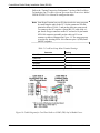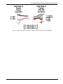
1
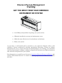
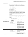
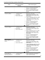
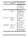
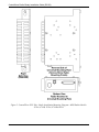
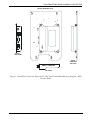
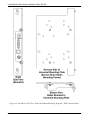
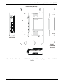
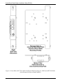
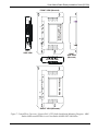
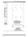
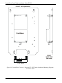
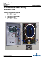
Instruction Manual D5138 Part: D301687X012 March, 2011 ControlWave Radio-Ready Installation Guide For field installation of radios in: ControlWave Corrector ControlWave EFM ControlWave ExpressPAC ControlWave GFC ControlWave GFC Plus Remote Automation Solutions www.EmersonProcess.com/Remote ControlWave IMPORTANT! READ INSTRUCTIONS BEFORE STARTING! Be sure that these instructions are carefully read and understood before any operation is attempted. Improper use of this device in some applications may result in damage or injury. The user is urged to keep this book filed in a convenient location for future reference. These instructions may not cover all details or variations in equipment or cover every possible situation to be met in connection with installation, operation or maintenance. Should problems arise that are not covered sufficiently in the text, the purchaser is advised to contact Emerson Process Management, Remote Automation Solutions division (RAS) for further information. EQUIPMENT APPLICATION WARNING The customer should note that a failure of this instrument or system, for whatever reason, may leave an operating process without protection. Depending upon the application, this could result in possible damage to property or injury to persons. It is suggested that the purchaser review the need for additional backup equipment or provide alternate means of protection such as alarm devices, output limiting, fail-safe valves, relief valves, emergency shutoffs, emergency switches, etc. If additional information is required, the purchaser is advised to contact RAS. RETURNED EQUIPMENT WARNING When returning any equipment to RAS for repairs or evaluation, please note the following: The party sending such materials is responsible to ensure that the materials returned to RAS are clean to safe levels, as such levels are defined and/or determined by applicable federal, state and/or local law regulations or codes. Such party agrees to indemnify RAS and save RAS harmless from any liability or damage which RAS may incur or suffer due to such party's failure to so act. ELECTRICAL GROUNDING Metal enclosures and exposed metal parts of electrical instruments must be grounded in accordance with OSHA rules and regulations pertaining to "Design Safety Standards for Electrical Systems," 29 CFR, Part 1910, Subpart S, dated: April 16, 1981 (OSHA rulings are in agreement with the National Electrical Code). The grounding requirement is also applicable to mechanical or pneumatic instruments that include electrically operated devices such as lights, switches, relays, alarms, or chart drives. EQUIPMENT DAMAGE FROM ELECTROSTATIC DISCHARGE VOLTAGE This product contains sensitive electronic components that can be damaged by exposure to an electrostatic discharge (ESD) voltage. Depending on the magnitude and duration of the ESD, this can result in erratic operation or complete failure of the equipment. Read supplemental document S14006 for proper care and handling of ESD-sensitive components. Remote Automation Solutions A Division of Emerson Process Management 1100 Buckingham Street, Watertown, CT 06795 Telephone (860) 945-2200 Emerson Process Management Training GET THE MOST FROM YOUR EMERSON INSTRUMENT OR SYSTEM Avoid Delays and problems in getting your system on-line Minimize installation, start-up and maintenance costs. Make the most effective use of our hardware and software. Know your system. As you know, a well-trained staff is essential to your operation. Emerson offers a full schedule of classes conducted by full-time, professional instructors. Classes are offered throughout the year at various locations. By participating in our training, your personnel can learn how to install, calibrate, configure, program and maintain your Emerson products and realize the full potential of your system. For information or to enroll in any class, go to http://www.EmersonProcess.com/Remote and click on “Educational Services” or contact our training department in Watertown at (860) 945-2200. This page is intentionally left blank ControlWave Radio-Ready Installation Guide (D5138) Introduction You can order certain ControlWave-series devices with a radio preinstalled at the factory, or as “radio-ready” in which you can install a radio in the field. These ControlWave units are: ControlWave Corrector ControlWave EFM ControlWave ExpressPAC ControlWave GFC ControlWave GFC Plus Radio-ready units contain all hardware necessary to field install the radio except the radio itself, and the radio installation hardware such as screws, nuts, and washers. Radio-ready units include either an internal RF radio cable with bulk head antenna connector, or an internal RF radio cable that mates to an optional polyphaser (surge impulse suppressor). Radios ship from the factory with all necessary installation hardware for mounting on the radio mounting bracket or radio mounting plate. Table 1 shows the supported radios and the installation hardware included. Table 1. Radios Supported Radio MDS 4710A Remote Data Transceiver (Radio) MDS 4710B Data Transceiver (Radio) Associated Installation Hardware four (4) 6-32 x 5/16 mounting screws power cable radio interface cable four (4) 6-32 x 5/16 mounting screws power cable radio interface cable Refer to these Figures Figure 1. ControlWave Corrector / ExpressPAC / GFC Radio Installation/Mounting Diagram - MDS Radios (Models 4710A, 4710B, 9710A, 9710B & 9810) Figure 2. ControlWave GFC Plus - Radio Installation/Mounting Diagram - MDS Radios Models 4710A, 4710B, 9710A, 9710B & 9810 Figure 16. ControlWave EFM Radio Installation - Mounting Diagram Figure 17. ControlWave EFM - Radio Mounting Bracket - Radio Installation Diagram Figure 1. ControlWave Corrector / ExpressPAC / GFC Radio Installation/Mounting Diagram - MDS Radios (Models 4710A, 4710B, 9710A, 9710B & 9810) Figure 2. ControlWave GFC Plus - Radio Installation/Mounting Diagram - MDS Radios Models 4710A, 4710B, 9710A, Issued Mar-2011 1 ControlWave Radio-Ready Installation Guide (D5138) Radio Associated Installation Hardware Refer to these Figures 9710B & 9810 MDS 9710A Remote Data Transceiver (Radio) four (4) 6-32 x 5/16 mounting screws power cable radio interface cable Figure 16. ControlWave EFM Radio Installation - Mounting Diagram Figure 17. ControlWave EFM - Radio Mounting Bracket - Radio Installation Diagram Figure 1. ControlWave Corrector / ExpressPAC / GFC Radio Installation/Mounting Diagram - MDS Radios (Models 4710A, 4710B, 9710A, 9710B & 9810) Figure 2. ControlWave GFC Plus - Radio Installation/Mounting Diagram - MDS Radios Models 4710A, 4710B, 9710A, 9710B & 9810 Figure 16. ControlWave EFM Radio Installation - Mounting Diagram MDS 9710B Data Transceiver (Radio) MDS 9810 Spread Spectrum Data Transceiver (Radio) four (4) 6-32 x 5/16 mounting screws power cable radio interface cable four (4) 6-32 x 5/16 mounting screws power cable radio interface cable Figure 17. ControlWave EFM - Radio Mounting Bracket - Radio Installation Diagram Figure 1. ControlWave Corrector / ExpressPAC / GFC Radio Installation/Mounting Diagram - MDS Radios (Models 4710A, 4710B, 9710A, 9710B & 9810) Figure 2. ControlWave GFC Plus - Radio Installation/Mounting Diagram - MDS Radios Models 4710A, 4710B, 9710A, 9710B & 9810 Figure 16. ControlWave EFM Radio Installation - Mounting Diagram Figure 17. ControlWave EFM - Radio Mounting Bracket - Radio Installation Diagram Figure 1. ControlWave Corrector / ExpressPAC / GFC Radio Installation/Mounting Diagram - MDS Radios (Models 4710A, 4710B, 9710A, 9710B & 9810) Figure 2. ControlWave GFC Plus - Radio Installation/Mounting Diagram - MDS Radios Models 4710A, 4710B, 9710A, 9710B & 9810 MDS entraNET 900 Extended Range IP Networking Transceiver 2 four (4) 6-32 x 5/16 mounting screws power cable Figure 16. ControlWave EFM Radio Installation - Mounting Diagram Figure 17. ControlWave EFM - Radio Mounting Bracket - Radio Installation Diagram Figure 5. ControlWave Corrector / GFC Radio Installation/Mounting Diagram MDS entraNET 900 Radio Issued Mar-2011 ControlWave Radio-Ready Installation Guide (D5138) Radio MDS iNET 900 Ethernet Radio Associated Installation Hardware radio interface cable four (4) 6-32 x 5/16 mounting screws power cable radio interface cable Refer to these Figures Figure 16. ControlWave EFM Radio Installation - Mounting Diagram Figure 17. ControlWave EFM - Radio Mounting Bracket - Radio Installation Diagram Figure 7. ControlWave Corrector / ExpressPAC / GFC Radio Installation/Mounting Diagram - MDS Radios MDS entraNET900 Access Point Radio & MDS iNET 900 Radios Figure 9. ControlWave GFC Plus Radio Installation/Mounting Diagram - MDS iNET 900 Radios MDS Transnet 900 Spread Spectrum Data Transceiver FreeWave Radio Spread Spectrum Data Transceiver Model FGRM-501X005 four (4) 6-32 x 5/16 mounting screws four (4) #6 flat 5/16 O.D. washers four (4) 6-32 hex nuts power cable radio interface cable eight (8) 6-32 x 5/16 pan head screws four (4) 6-32 x 0.500 F/F standoffs four (4) 6-32 x 5/16 countersunk screws radio interface cable Figure 16. ControlWave EFM Radio Installation - Mounting Diagram Figure 17. ControlWave EFM - Radio Mounting Bracket - Radio Installation Diagram Figure 3. ControlWave Corrector /ExpressPAC / GFC Radio Installation/Mounting Diagram - MDS Transnet Radio Figure 4. ControlWave GFC Plus - Radio Installation/Mounting Diagram - MDS Transnet Radio Figure 16. ControlWave EFM Radio Installation - Mounting Diagram Figure 17. ControlWave EFM - Radio Mounting Bracket - Radio Installation Diagram Figure 10. ControlWave Corrector / ExpressPAC / GFC Radio Installation/Mounting Diagram – FreeWave Radio Figure 11. ControlWave EFM / ExpressPAC / GFC Plus - Radio Installation/Mounting Diagram – FreeWave Radio Figure 18. Cable Diagram for FreeWave Radio to COM2 (TB3) Intf. & Radio Power Figure 19. PC Connected to FreeWave Radio) - (Part Number VASC2009DC) Issued Mar-2011 Figure 6. ControlWave GFC Plus Radio Installation/Mounting Diagram - MDS entraNET 900 Radio (Serial Remote & Ethernet Remote Radios) 3 ControlWave Radio-Ready Installation Guide (D5138) Installation WARNING Radios supplied by Emerson for use in the ControlWave Corrector, ControlWave ExpressPAC, ControlWave GFC, and ControlWave GFC Plus are approved for use in Class I, Division 2, Groups C, and D hazardous locations. Radios supplied by Emerson for use in the ControlWave EFM are approved for use in Class I, Division 2, Groups A, B, C, and D hazardous locations. Radios may also be used in nonhazardous locations. The installer must be familiar with hazardous location installation guidelines before installation or maintenance is undertaken. Do no begin radio installation or service unless the area is known to be non-hazardous. Only the radios listed in Table 1 may be used in Class I, Division 2, hazardous locations! Use of other radios in these locations is prohibited. Avoid operating equipment during an electrical storm. An impulse suppressor may save equipment from danger, but should not be considered as being safe for personnel. Follow all cautions and warnings in the manual for your ControlWave controller/flow computer. Installation Steps 1. Open the front cover of the ControlWave device. Refer to Table 1 to reference the figure(s) that apply for your ControlWave device. 2. Remove the radio mounting plate/bracket. To do this, loosen the 3. 4. 5. 6. 7. 4 pan head screws that secure it to the battery mounting bracket (or in the case of the GFC Plus or EFM that secure it to the fabrication panel). Slide the radio mounting plate/bracket upward until you can remove it. Using the mounting hardware provided with the radio, mount and secure the radio to the radio mounting plate/bracket you removed in Step 2. Re-install the radio mounting plate/bracket (now with the radio attached) that you removed in Step 2 by sliding it in and tightening the screws. Connect the radio’s RF cable to the radio. Connect the other end of the radio’s internal RF cable to a polyphaser or an RF bulk head/antenna interface connector. (See Figure 12, Figure 13, Figure 14, or Figure 15, as appropriate.) Connect the user-supplied antenna cable to either the polyphaser or bulk head antenna cable connector jack on the bottom of the ControlWave device. Plug the radio interface cable into the radio’s communication port. Plug the other end of this cable into COM2 of the CPU/System Controller board assembly (or EFM CPU module). For non-EFM units, in the case of the FreeWave radio, the interface cable supplies power to the radio from CPU connector TB1 as follows: Issued Mar-2011 ControlWave Radio-Ready Installation Guide (D5138) TB1-5 = Aux. Power Out+ (Red), TB1-6 = GND (Black). 8. For MDS radios, remove the MDS radio’s power connector from the radio, and connect the unterminated ends of the MDS power cable to the MDS power connector (Red = Pos., and Black = GND). Plug the end of the MDS radio power cable that you just dressed into the MDS radio. For ControlWave GFC, GFC Plus, Corrector, or EPAC, connect the other end of the MDS radio power cable to connector TB1’s AUX PWR terminals on the CPU/System Controller board (Red = TB1-5, Black = TB1-6). For ControlWave EFM, connect the other end of the MDS radio power cable to connector TB3 on the Power Distribution board. 9. After testing the unit, secure the door. FRONT VIEW (Mounted) MDS Radios Models: 4710A, 4710B, 9710A, 9710B & 9810 RIGHT SIDE VIEW (Mounted) + BOTTOM VIEW Figure 1. ControlWave Corrector / ExpressPAC / GFC Radio Installation/Mounting Diagram - MDS Radios (Models 4710A, 4710B, 9710A, 9710B & 9810) Issued Mar-2011 5 ControlWave Radio-Ready Installation Guide (D5138) Figure 2. ControlWave GFC Plus - Radio Installation/Mounting Diagram - MDS Radios Models 4710A, 4710B, 9710A, 9710B & 9810 6 Issued Mar-2011 ControlWave Radio-Ready Installation Guide (D5138) + FRONT VIEW (Mounted) LEFT SIDE VIEW RIGHT SIDE VIEW (Mounted) MDS Transnet TOP VIEW Figure 3. ControlWave Corrector /ExpressPAC / GFC Radio Installation/Mounting Diagram - MDS Transnet Radio Issued Mar-2011 7 ControlWave Radio-Ready Installation Guide (D5138) Figure 4. ControlWave GFC Plus - Radio Installation/Mounting Diagram - MDS Transnet Radio 8 Issued Mar-2011 ControlWave Radio-Ready Installation Guide (D5138) + FRONT VIEW (Mounted) LEFT SIDE VIEW RIGHT SIDE VIEW (Mounted) MDS entraNET 900 TOP VIEW Figure 5. ControlWave Corrector / GFC Radio Installation/Mounting Diagram - MDS entraNET 900 Radio Issued Mar-2011 9 ControlWave Radio-Ready Installation Guide (D5138) Figure 6. ControlWave GFC Plus Radio Installation/Mounting Diagram - MDS entraNET 900 Radio (Serial Remote & Ethernet Remote Radios) 10 Issued Mar-2011 ControlWave Radio-Ready Installation Guide (D5138) + MDS entraNET 900 Access Point Radio FRONT VIEW (Mounted) LEFT SIDE VIEW RIGHT SIDE VIEW (Mounted) MDS iNET 900 Radios BOTTOM VIEW FRONT VIEW (Mounted) Figure 7. ControlWave Corrector / ExpressPAC / GFC Radio Installation/Mounting Diagram - MDS Radios MDS entraNET900 Access Point Radio & MDS iNET 900 Radios Issued Mar-2011 11 ControlWave Radio-Ready Installation Guide (D5138) Figure 8. ControlWave GFC Plus Radio Installation/Mounting Diagram - MDS entraNET 900 Radio (Access Point Radio) 12 Issued Mar-2011 ControlWave Radio-Ready Installation Guide (D5138) Figure 9. ControlWave GFC Plus Radio Installation/Mounting Diagram - MDS iNET 900 Radios Issued Mar-2011 13 ControlWave Radio-Ready Installation Guide (D5138) FRONT VIEW (Mounted) FreeWave RIGHT SIDE VIEW (Mounted) TOP VIEW Figure 10. ControlWave Corrector / ExpressPAC / GFC Radio Installation/Mounting Diagram – FreeWave Radio 14 Issued Mar-2011 ControlWave Radio-Ready Installation Guide (D5138) Figure 11. ControlWave EFM / ExpressPAC / GFC Plus - Radio Installation/Mounting Diagram – FreeWave Radio Issued Mar-2011 15 ControlWave Radio-Ready Installation Guide (D5138) Figure 12. Partial View – ControlWave GFC, EPAC, with/without Polyphaser Figure 13. Partial View - ControlWave GFC Plus with/without Polyphaser 16 Issued Mar-2011 ControlWave Radio-Ready Installation Guide (D5138) Figure 14. Partial View - ControlWave Corrector with/without Polyphaser Figure 15. Partial View - ControlWave EFM with/without Polyphaser Installed Issued Mar-2011 17 ControlWave Radio-Ready Installation Guide (D5138) FRONT VIEW SIDE VIEW A A A Models: 4710A, 4710B, 9710A, 9710B & 9810 Two Screws that Secure the Radio Mounting Bracket to the Fabrication Panel. B B B + RIGHT SIDE VIEW MDS entraNET 900 C C C + B B Serial Remote & Ethernet Remote Radios RIGHT SIDE VIEW C C MDS entraNET 900 Access Point Radio & MDS iNET 900 Radios D RIGHT SIDE VIEW D D + MDS Transnet D D RIGHT SIDE VIEW E E E E E FreeWave Location of Mounting Hardware that Secures the Radio to the Radio Mounting Bracket. A = MDS Models 4710A, 4710B, 9710A, 9710B & 9810 B = MDS entraNET 900 Serial Remote & Ethernet Remote C = MDS entraNET 900 Access Point & MDS iNET 900 D = MDS TRANSNET E = FreeWave Figure 16. ControlWave EFM Radio Installation - Mounting Diagram 18 Issued Mar-2011 ControlWave Radio-Ready Installation Guide (D5138) Figure 17. ControlWave EFM - Radio Mounting Bracket - Radio Installation Diagram Additional FreeWave Information The FreeWave Spread Spectrum Data Transceiver Model FGRM501X005 User Manual contains in-depth details on modem parameters, operation, installation, tuning transceiver performance, and more. Copies of the FreeWave Spread Spectrum Data Transceiver Model FGRM-501X005 User Manual can be obtained from FreeWave Technologies, Inc. (electronically) by contacting their Technical Support Group. FreeWave Tech. Support can be reached at 303-444-3862 or at www.freewave.com. Issued Mar-2011 19 ControlWave Radio-Ready Installation Guide (D5138) Follow the “Tuning Transceiver Performance” section of the FreeWave Technologies, Inc. FreeWave Spread Spectrum Data Transceiver Model FGRM-501X005 User Manual to configure the radio. Note: Start HyperTerminal on your PC then invoke the setup program by connecting the radio to the PC. Set the parameters for that terminal to those of Table 2, and put the radio into setup mode. To connect to the PC requires a special RS-232 cable with a 9pin female D-type connector on the PC end and a 10-pin female MTA-100 connector assembly on the radio end. You can construct a cable as illustrated in Figure 18. The setup program is invoked by shorting MTA-100 connector pins 4 (GND) and 2 (MENU) together. Table 2. FreeWave Setup Menu Terminal Settings Parameter Baud Rate Setting 19,200 Data Rate 8 Parity None Stop Bits 1 Parity Check None/Off Carrier Detect None/Off Figure 18. Cable Diagram for FreeWave Radio to COM2 (TB3) Intf. & Radio Power 20 Issued Mar-2011 ControlWave Radio-Ready Installation Guide (D5138) Figure 19. PC Connected to FreeWave Radio) - (Part Number VASC2009DC) Issued Mar-2011 21 ControlWave Radio-Ready Installation Guide Instruction Manual D5138 March, 2011 NOTICE Emerson Process Management Remote Automation Solutions 1100 Buckingham Street Watertown, CT 06795 Phone: +1 (860) 945-2262 Fax: +1 (860) 945-2525 www.EmersonProcess.com/Remote Emerson Process Management Remote Automation Solutions 6338 Viscount Rd. Mississauga, Ont. L4V 1H3 Canada Phone: 905-362-0880 Fax: 905-362-0882 www.EmersonProcess.com/Remote Emerson Process Management SA de CV Calle 10 #145 Col. San Pedro de los Pinos 01180 Mexico, D.F. Mexico T +52 (55) 5809-5300 F +52 (55) 2614-8663 www.EmersonProcess.com/Remote Emerson Process Management, Ltd. Remote Automation Solutions Blackpole Road Worcester, WR3 8YB United Kingdom Phone: +44 1905 856950 Fax: +44 1905 856969 www.EmersonProcess.com/Remote Emerson Process Management AP Pte Ltd. Remote Automation Solutions Division 1 Pandan Crescent Singapore 128461 Phone: +65-6770-8584 Fax: +65-6891-7841 www.EmersonProcess.com/Remote “Remote Automation Solutions (“RAS”), division of Emerson Process Management shall not be liable for technical or editorial errors in this manual or omissions from this manual. RAS MAKES NO WARRANTIES, EXPRESSED OR IMPLIED, INCLUDING THE IMPLIED WARRANTIES OF MERCHANTABILITY AND FITNESS FOR A PARTICULAR PURPOSE WITH RESPECT TO THIS MANUAL AND, IN NO EVENT SHALL RAS BE LIABLE FOR ANY INCIDENTAL, PUNITIVE, SPECIAL OR CONSEQUENTIAL DAMAGES INCLUDING, BUT NOT LIMITED TO, LOSS OF PRODUCTION, LOSS OF PROFITS, LOSS OF REVENUE OR USE AND COSTS INCURRED INCLUDING WITHOUT LIMITATION FOR CAPITAL, FUEL AND POWER, AND CLAIMS OF THIRD PARTIES. Bristol, Inc., Bristol Babcock Ltd, Bristol Canada, BBI SA de CV and the Flow Computer Division are wholly owned subsidiaries of Emerson Electric Co. doing business as Remote Automation Solutions (“RAS”), a division of Emerson Process Management. FloBoss, ROCLINK, Bristol, Bristol Babcock, ControlWave, TeleFlow and Helicoid are trademarks of RAS. AMS, PlantWeb and the PlantWeb logo are marks of Emerson Electric Co. The Emerson logo is a trademark and service mark of the Emerson Electric Co. All other trademarks are property of their respective owners. The contents of this publication are presented for informational purposes only. While every effort has been made to ensure informational accuracy, they are not to be construed as warranties or guarantees, express or implied, regarding the products or services described herein or their use or applicability. RAS reserves the right to modify or improve the designs or specifications of such products at any time without notice. All sales are governed by RAS’ terms and conditions which are available upon request. © 2011 Remote Automation Solutions, division of Emerson Process Management. All rights reserved.