1
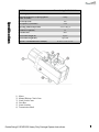
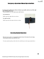
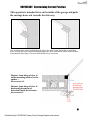
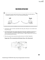
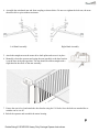
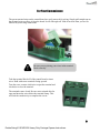
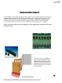
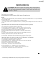
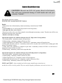
Instruction Manual for the E-SCAR 1602 Heavy Duty Carriage Door Opener WARNING - Read all instructions before beginning installation or use of this door opener. This operator exerts a high level of force. Exercise caution at all times and stay clear of the system during operation. Estate Swing E-SCAR1602 Heavy Duty Carriage Opener Instructions. Estate Swing Summary of Functions The Estate Swing is only to be used for vehicular swing doors in a Class I setting. Class I: A vehicular door opener (or system) intended for use in a home of one-to-four single family dwelling, or a garage or parking area associated therewith. The Estate Swing automated system was designed and built for controlling vehicle access. Do not use for any other purpose. The internal/external automation with articulated arms automates residential swing -leaf carriage doors with leaves of up to 8’ in length. It consists of an irreversible electro-mechanical operator with guard and an articulated-arm activation system to be fitted to the door with the appropriate accessories. The irreversible system ensures the door is mechanical locked when the motor is not operating. A manual release makes it possible to move the door in the event of a power-cut or fault. Keep this manual safely stored after installation. Serial Number__________________________ Date of Purchase_______________________ Place of Purchase______________________ Have this information on hand while handling all service and warranty issues. Estate Swing E-SCAR1602 Heavy Duty Carriage Opener Instructions. MODEL Power Supply Rated Absorbed Power (Amperage pull on a 120V AC outlet) Specifications Max Torque (Nm) Use frequency (cycles/hour) Operating ambient temperature Gearmotor weight (lbs) Protection class Door leaf max length (ft.) Door leaf max weight (lbs.) Operator overall dimensions LxHxD(in.) 1) 2) 3) 4) 5) 6) Estate Swing E-SCAR 1600 24VAC 50VA transformer (120VA max) 5 Amp/ 200 > 100 -4 to 131 Deg F 35 IP44 Up to 8 Up to 800 12 5/8” x 6 7/8” x 6 3/8” Motor Manual Release Clutch Cam Limit Switch Cams Gear Box Limit Switches Transmission Shaft Estate Swing E-SCAR1602 Heavy Duty Carriage Opener Instructions. 1 Estate Swing Parts List Motor Box Contents 1. Motor Mount Bolts (4) 2. Motor Mount Washers (4) 3. Motor Mount Spring Washers (4) 4. Motor Mount Lock Nut (4) 5. Cover Bolts (2) 6. Cover Blot O-Rings (2) 7. Motor Wire Gasket (1) 8. Manual Clutch Assembly (1) 9. Clutch Keys (2) 10. Cover Bolt Plugs (2) 3/8 Concrete anchors for column (4) Motor Arm Contents 1. Pivot Bolts (2) 2. Nylon Pivot Bushings (6) 3. Lock Nuts (2) 5/16” hex bolts for door (cut to size) (2) Control / Power Contents 1. 2. 3. 4. 5. Control Board Receiver Transmitter Transformer Control Box 2 1 Estate Swing E-SCAR1602 Heavy Duty Carriage Opener Instructions. 5 3 4 2 Tools Needed Power Drill and appropriately sized bits. Crescent Wrench Flat Head Screwdriver Nuts, Bolts, Anchors and Washers (see below) C-Ring Pliers Phillips Head Screwdriver Tape Measure Level Wire Strippers C-clamps Carpenters Clamps Other items that may be needed prior to commencing installation. 16, 14 or 12 gauge, 2 conductor stranded low voltage wire will be required to run power to your operator. Length is deter mined by distance between tr ansfor mer power supply and the control box. A voltage meter and digital camera may be necessary to run diagnostic checks. 4 - 3/8” fasteners may be needed to connect the Base Plate to the wall. Length and style will be determined by what is needed for a secure anchor for your material door. The kit includes concrete anchors for block construction garages. 2 - 5/16” fasteners may be needed to connect the Door Mounting Bracket to the door. Length and style will be determined by what is needed for a secure anchor for your material door. The kit includes hex bolts designed to be inserted through your door. Other methods can be used alternatively. Hardware to attach the control box to a wall. 3 Estate Swing E-SCAR1602 Heavy Duty Carriage Opener Instructions. Emergency & Operational Manual Operation Mode In emergencies pull down on the red release rope until you hear two clicks and this will release the door. Test periodically for correct placement and function. For left-hand side: Pull the rope to the right clockwise to release For right-hand side: Pull the rope to the left counter-clockwise to release Restoring Standard Operation Disconnect power prior to re-engaging the manual release. If the board is active injury from unexpected motor movement can occur. To restore operation push up on the release lever until the rope is at the top as pictured above. 4 Estate Swing E-SCAR1602 Heavy Duty Carriage Opener Instructions. IMPORTANT: Determining Correct Position This operator is intended to be on the inside of the garage and push the carriage doors out towards the driveway. The mounting plate can be positioned on the side of the frame using four of the six mounting holes or above the frame. In both mounting options the drive shaft should further inside the door frame than the door hinge. The drive shaft should always face down. Distance from hinge of door to inside mounting surface for the opener = Do not exceed 12” Distance from hinge of door to horizontal placement of driveshaft inside door frame = Do not exceed 6” 5 Estate Swing E-SCAR1602 Heavy Duty Carriage Opener Instructions. Installation of Operator The operator base plate and articulated arm are designed either for right-handed or left-handed installation. There is no pre-determined designation. 1. Utilizing the center of the drive shaft hole in the base plate, find your correct setback from the previous page. 2. Secure the base plate to the column using screws and a proper anchoring system for your type of wall material. If using the provided block wall anchors drill holes using a 5/8” concrete bit and a hammer drill. For added strength we suggest filling the hole with epoxy prior to hammering in the anchor. 3. Place the operator motor onto the base plate and secure it with the 4 long bolts. Important: The transmission shaft must always face downward. 6 Estate Swing E-SCAR1602 Heavy Duty Carriage Opener Instructions. 4. Assemble the articulated arm and front coupling as shown below. Do not over tighten the lock nuts, the arms should be able to pivot without resistance. Left Hand Assembly Right Hand Assembly 5. Attach the straight arm on the motor drive shaft spline and secure it in place 6. Manually release the operator and swing the arm assembly so the door bracket is on the door in the open position. The arm should be almost straight with a slight bend in the elbow of the arm assembly. 7. Ensure the arm is level and attach the door bracket using the 5/16 bolts. Once the bolts are attached the remainder can be cut off. 8. Relock the operator and assemble the motor housing. 7 Estate Swing E-SCAR1602 Heavy Duty Carriage Opener Instructions. For Your Convenience The green terminal strips on the control board are easily removed for wiring. Simply pull straight out on the terminal strip to remove it from the board. It will slide right off. Slide it back on when you are finished with your wiring connections. Be sure you are placing your wires in the terminal block correctly. Take the terminal block off of the control board to insert wires. Hold with screw terminals facing upward. Turn the screw counter-clockwise to open the terminal and clockwise to close the terminal. The terminals come closed. Be sure not to mistake this for open and insert the wires below the terminal clamp. This will lack the conductivity to complete the circuit. 8 Estate Swing E-SCAR1602 Heavy Duty Carriage Opener Instructions. Setting Limit Switches 1. Loosen the screw that holds the limit switch rings in place. 2. Move the door into the full open position. Move the top ring until it is pushing the switch on the top limit switch in. 3. Move the door to the closed position. Move the bottom ring until it is pushing the switch on the bottom limit switch. 4. Retighten the limit switch ring screw to hold the rings in the correct place on the driveshaft. 9 Estate Swing E-SCAR1602 Heavy Duty Carriage Opener Instructions. Temporary Safety Jumpers For the highest level of safety, the Estate Swing systems are set up with Normally Closed safety terminals. This means that in order for the door opener to move these terminals must be closed either through a safety device (recommended) or with jumpers. Temporary safety jumpers are provided in the control box hardware bag for jumping terminals PHOTO and GND together It is recommended not to use any accessories until setup and programming are complete. NOTE: If not using safety devices the temporary safety jumper must remain in for the door operator to move. To the left is our recommended safety set up. It consists of safety edges mounted on the door on the outside to react rapidly to impact and photo beams at the base of the door to halt movement of the doors with obstruction. 10 Estate Swing E-SCAR1602 Heavy Duty Carriage Opener Instructions. Wiring the Operator Motors LEFT OPERATOR OPENS FIRST: Motor1 L1-1: 16 AWG Red Motor1 L1-2: 16 AWG Black Motor2 L2-1: 16 AWG Black Motor2 L2-2: 16 AWG Red Limit1 OL1: Yellow Limit1 COM1: Red Limit1 CL1: Black Limit2 OL2: Yellow Limit2 COM2: Red Limit2 CL2: Black If you require the Right mounted door to open first change wires to: Right hand motor: Motor 1 L1-1: Black, Motor1 L1-2: Red, Limits on Limit1 block Left hand motor: Motor 2 L2-1: Red, Motor2 L2-2: Black, Limits on Limit2 block 11 Estate Swing E-SCAR1602 Heavy Duty Carriage Opener Instructions. Estate Swing 433 Plug-in Receiver 1. With the red plug already inside the control box, run the grey receiver wire out of the box through one of the water tight connections. 2. Find a location for the receiver box on the door post or a fence post that is within the length of the receiver wire. 3. Using a #6 screw attached the top of the receiver to the post. If you are happy with this position use the small provided set screw in the bottom hole to secure the receiver in place. 4. Attach the receiver wire to the terminals as seen below. Please note that you will find a factory installed jumper wire connected on the receiver. Leave this jumper wire in place. One of the terminals that has the jumper wire will have the White wire added to the terminal. 12 Estate Swing E-SCAR1602 Heavy Duty Carriage Opener Instructions. Estate Swing 433 Plug-in Receiver (cont.) 5. Plug the red clip inside the control box into the control board. The groove in the red clips should snap into the guide on the 5 prong connector. (Fig 1) 6. The red power light should come on the receiver. (Fig 2) 7. Program your remotes to the receiver: A. Press and release the LEARN1 button at the top of Fig. 1 the receiver board (ex 1). The learn LED will illuminate steady (ex 2). (Fig 3) B. Press and hold the button on the remote you wish to program to the receiver. C. Hold the remote button until the Learn LED flashes and then turns off. (caution your door opener may be triggered during this process) D. Repeat A through C for all additional remotes. Fig. 2 NOTES ABOUT REMOTES: You can program up to 400 codes into the receiver. This could mean 1 button on 400 different remotes or this could mean all 4 buttons on 100 remotes or anything in between. Some choose to program all 4 buttons to a single receiver if they are not using multiple doors to eliminate pressing the incorrect button on the remote. To do so follow the programming above with each button of the remote. You can erase all programmed codes by holding Learn 1 until the Learn LED comes ON and then turns OFF. 8. Put the cover on the receiver and secure it in place using the provided screw. Fig. 3 IMPORTANT: The r eceiver is a dr ip pr oof r eceiver . This means that it is designed to prevent water from accessing the inside of the receiver when the water is moving downward with gravity (rain for example). DO NOT mount the r eceiver anyplace that water may access it fr om another angle. For example: Do not mount near sprinklers. Do not mount the receiver horizontally. Do not mount the receiver near a flat surface where water could splash upwards. Estate Swing E-SCAR1602 Heavy Duty Carriage Opener Instructions. 13 Power Kit includes 1) 24V transformer. The transformer supplied has 2 screw terminals to connect to. You may locate the transformer up to 200’ away from the control board using 16 gauge, 2 conductor stranded direct burial low voltage wire. Do not use solid core wire. Allow a minimum of 4’ of wire between the transformer and the control board. Using the provided wire nuts, connect the wire (not provided) from the transformer to the two yellow wires on the control board marked TRAN. There is no polarity. Never run 110VAC power directly to the Estate Swing. This will destroy the Estate Swing control board. Never connect the power wire with the transformer plugged in. Contact between the two lead wires, even for a second, will destroy the transformer. Transformers are only warranted if the internal fuse is not blown. If the fuse is blown an outside factor (shorting, surge, water, etc) has caused the transformer not to function. Plug the transformer into a 110 V AC outlet. The transformer is not weather proof and must be kept inside the garage and out of weather. Two 12V DC batteries (Max 5 a/h per battery) may be run in series as backup to the 24V transformer power. Running two 12V batteries in series creates a 24V system, you cannot run them in parallel (see diagram above) 14 Estate Swing E-SCAR1602 Heavy Duty Carriage Opener Instructions. Setting Operating Parameters Important Dip Switch Setting Verify the 3 dipswitches are as follows: 1. DOWN 2. UP 3. DOWN First Run This is our recommended procedure to run the doors for the first time. PUSH 1 or PUSH 2 to increase or decrease the parameter. Then press SET button to move to the next parameter. 1. Press SET button to begin. 2. LED shows P1: Press Push 1 to get P1 setting to 30. 3. Press SET button. 4. LED shows P2: Press Push 1 to get P2 setting to 10. 5. Press SET button. 6. LED shows P3: Press Push 1 to get P3 setting to 30. 7. Press SET button. 8. LED shows P4: Press Push 1 to get P4 setting to 3. 9. Press SET button. 10. LED shows P5: Press Push 1 to get P5 setting to 2. 11. Press SET button. 12. LED shows P6: Press Push 1 to get P6 setting to 10. 13. Press SET to finish. You should hear 3 beeps; this indicates parameter programming is finished. Manually unlock the doors, then move them half-way and re-engage. Activate using Push 1 button (as shown above) The doors should run open. Press Push 1 again and the doors should run closed. The doors are now set up for regular usage. Estate Swing E-SCAR1602 Heavy Duty Carriage Opener Instructions. 5.1 Operating Parameters Customization 1. LED shows P1: P1 is for setting your run time. The run time will be determined from the time you had determined during the set up of the limit switches. Take that determined run time and add 1 second. So if it takes 10 seconds to get from closed to open between limit switches; set the run time to 11 seconds. The options are 0-99 seconds. 2. LED shows P2: P2 is for setting your slow down time. The door opener will slow down to half speed after the time set on P2 expires. If you wish to have the doors open and close faster make the slow down start time a longer period of time. If you want to put less stress on the gears and door set the slow time shorter to slow the momentum sooner. The options will adjust to match the previously set run time. NOTE: motor must be in slow down to detect limits—be sure this number does not exceed the time the motor take to move from one limit to the other. 3. LED shows P3: P3 is the force setting, the lower the number the easier the doors will reverse directions when it meets resistance. This number may have to be changed to a higher setting if your doors are obstructing unexpectedly. The number should be set to the highest number during initial setup and reduced to the point of reliable operation that takes into account change in door resistance throughout the year. The options are 0-32. 4. LED shows P4: P4 is for setting a delay between leafs if you have overlapping doors or a door lock. The motor wired into the master terminals (1) opens first if there is a delay and closes second. It is recommended to have a delay of 3 seconds to avoid any jamming issues between leafs. 5. LED shows P5: P5 is the release for the door lock – this option determines the length of time 24VDC will be sent out of terminals E_LOCK. The options are 1-4 seconds. 6. LED shows P6: P6 is the delay for automatic re-close from the open position – this option needs to be turned on using the dip switch on the board. The options are 0-99 seconds. 15 Estate Swing E-SCAR1602 Heavy Duty Carriage Opener Instructions. Troubleshooting If the door opener will not move but the board is counting the run time: • Check wiring connections. • Be sure the arms are locked and not in manual operation. • If not using slave limit switches, be sure jumpers are in place. • Check the left hand fuse near the power supply—the proper way to inspect a fuse is to remove it from its clips and check for continuity. If the door opener moves a few inches or feet and stops or reverses directions: • Increase the force setting (P3). • Check the setback. The setback of the operator is important to correct operation due to leverage the arm will have on the door. • Check the battery voltage. Proper voltage should be between 13.4 – 13.8 and drop no more than a quarter of a volt under load. • Disconnect accessories that may be triggering the door a second time. The most frequent issues are from exit sensors or other automatic opening devices. The door does not reach the desired stop points: • Adjust the limit switches. • Lengthen the run time parameter (P1). • Check setback— if setback is incorrect it will limit how far the door will move. If the door will open but will not close: • Manually move the door slightly off the open position and then trigger the door to go closed. If the door then moves closed the limits are most likely wired backwards. (Meaning the open limit is wired to closed and closed wired to open) • If you are not using safety devices the safety jumpers are in place. If PH is on display it is an issue with the safety jumper or a device in the safety terminals. • If you are using a safety device: - Check to make sure you are using the normally closed connection instead of the normally open. - Check to be sure there is continuity being provided between the common and normally closed wire of the safety device. If there is not continuity then refer to the installation guide of the device to set up properly. The display of the board will not light up: • Check the power supply for 24VAC. The arms are not wired in or properly wired on the limit switch connections. Without the limit switch connections being closed the board will not light up. More on next page 16 Estate Swing E-SCAR1602 Heavy Duty Carriage Opener Instructions. Troubleshooting The door opener is not stopping on the limit switches: • Remove all pre-installed jumpers from the limit switch terminals that have limits going to them. The slave door terminals come pre-jumped for single operation, if you are using a dual system pay particular attention to this detail and remove the jumpers when you put your limit switches in. • The limits are wired incorrectly—be sure that you are following the correct wiring diagram for pull to open or push to open. • For dual doors check that the delay between leafs is 2 or above. If both limits are triggered simultaneously there is a chance a limit could be missed. One or both arms are not moving: • Check to be sure wiring color pattern matches the installation (Example: push to open wiring for a push to open installation) - If the limits or motor are wiring opposite the installation the board will believe it is closed or open when it is actually the opposite and the arms will never move. • Check the limit wires are correctly in the terminal blocks. The terminal blocks come with the terminal clamps closed - however when the terminal clamps are closed there is a small space below them one could mistake as place to insert a wire. If this is done then conductivity of the connection will never be reached. • Push or pull on the door - if it moves the gears are disengaged and the door is in manual release mode. General fix for user to understand operation: - Unlock the door opener arm and move it to the half way position. Change the run time to a low number (example: 2). Run the operator repeatedly. - The operator should run one direction for a 2 count and then the other for a 2 count. After you feel you have it following the run time correctly and swinging level and easily, then start incrementally lengthening the run time. - Eventually the run time will allow the operator arm to reach both limit switches and your setup is complete. Dual door - Only one arm moves: • Check your dual settings - if the dip switch is changed to dual with the power on the setting will not take effect, turn the power off and then back on to have the dual dip switch take effect. NOTE: If one leaf of a dual door ever reaches its end limit before the other leaf starts moving, the leaf that hasn’t started moving will not begin: correct this by cycling the doors again and let it travel the full stroke or decrease the delay between leafs. The options are 0-9 seconds delay. 17 Estate Swing E-SCAR1602 Heavy Duty Carriage Opener Instructions. Troubleshooting If you call in for technical support or warranty support: Before any control boar d or motor will be permitted to be sent in for testing or warranty you will be required to e-mail digital photos to the technician. This is done in your best interest to save unnecessary shipping expenses and time lost. Many times we can come up with solutions to issues by seeing pictures that relay information that is impossible to relay through a phone conversation. Below are examples of control board pictures and motor pictures that we will be looking for: Picture shown is actual customer photo 18 Estate Swing E-SCAR1602 Heavy Duty Carriage Opener Instructions. Control Board Overview CAUTION! Do not r un 110V AC power direct to the boar d. This will cause permanent damage to both boards and void your warranty. Caution! Door Opener reactions to signals: PUSH1 and Receiver (PUSH 1 terminal, PUSH 1 button, 5 Prong Receiver): Details: • Will activate door with momentary contact (momentary contact between PUSH1 and V+) or if you momentarily press the PUSH1 button. • Controls both leaves in 2 leaf mode (Dip switch 2 in the ON position). • Acts as party mode control to suspend auto-reclose by activating while counting down auto-reclose in the open position. Operational Sequence for terminal with auto-close ON (Dip switch 1 in on position): 1. In closed position - momentary contact will open doors. 2. When opening - momentary contact will stop doors and then it will auto reclose. 3. When stopped mid cycle waiting auto reclose - momentary contact will move the door in the direction opposite what it was moving before stopped. 4. When open and counting auto-reclose pause time - momentary contact will stop pause time. 5. Stopped in open position from override of auto-reclose from PUSH1 or Receiver momentary contact will reactivate pause time and close door. 6. When closing - momentary contact will stop the door and then it will auto reclose. Operational Sequence for terminal with auto-close OFF (Dip switch 1 in off position): 1. In closed position - momentary contact will open doors. 2. When opening - momentary contact will stop doors. 3. When stopped mid cycle - momentary contact will move the door in the direction opposite what it was moving before stopped. 4. When open - momentary contact will close doors. 5. When closing - momentary contact will stop the door. 6. When stopped mid cycle - momentary contact will open the door. 7. When open with auto-reclose off - momentary contact will have no effect. 8. When closing - momentary contact will re-open the door. 19 Estate Swing E-SCAR1602 Heavy Duty Carriage Opener Instructions. Control Board Overview CAUTION! Do not r un 110V AC power direct to the boar d. This will cause permanent damage to both boards and void your warranty. Caution! Door Opener reactions to signals: PUSH2 (PUSH 2 terminal and PUSH 2 button): Details: • Will activate door with momentary contact (momentary contact between PUSH2 and V+). • Controls both leaves in 2 leaf mode (Dip switch 2 in the ON position) • Only opens the door, never closes it. • Pause time is able to be re-set if this terminal is closed through a momentary contact. Then the time will be reset, count down the pause time, and reclose. • Ideal for exit wand or exit loop. Operational Sequence for terminal with auto-close ON (Dip switch 1 in on position): 1. In closed position - momentary contact will open doors. 2. When opening - momentary contact will have no effect. 3. When stopped mid cycle from PUSH 1 or the Receiver - momentary contact will open the door. 4. When open with auto-reclose on - momentary contact will re-set pause time and will start counting again after release of momentary contact. 5. When pause time countdown is stopped in open from a momentary contact of PUSH 1 or the Receiver momentary contact will have no effect. 6. When closing - momentary contact will re-open the door. Operational Sequence for terminal with auto-close OFF (Dip switch 1 in off position): 1. In closed position - momentary contact will open doors. 2. When opening - momentary contact will have no effect. 3. When stopped mid cycle - momentary contact will open the door. 4. When open with auto-reclose off - momentary contact will have no effect. 5. When closing - momentary contact will re-open the door. PUSH 1 and PUSH 2 – these terminals can hold as many normally open connections as needed, they will be wired in parallel. They are used for keypads, push buttons, universal receivers, etc. 20 Estate Swing E-SCAR1602 Heavy Duty Carriage Opener Instructions. Control Board Overview Light: Sends pulses of 24VDC only while door is running, and whether it is open or closed. Motor 1: L1-1, L1-2 = 24VDC power to primary motor Motor 2: L2-1, L2-2 = 24VDC power to secondary motor Limit 1: OL1 = Open limit for single motor or master (normally closed) V+ = Common for limits, +12VDC CL1 = Closed limit for single motor (normally closed) Limit 2: OL2 = Open limit for slave motor (normally closed) V+ = Common for limits, +12VDC CL2 = Closed limit for slave motor (normally closed) Photocell: Button: Photo = Input for safety eye photo beam connection (normally closed) GND = Ground for photocell power/ground for photo connection V+ = +12VDC, Max 100 milliamps for photocell power +24V = +24VDC, Max 200 milliamps for accessory power PUSH 1 = Ground for Push 1 Accessory *PUSH 1 / V+ is for push buttons, keypads, receivers, or any other dry and momentary contact. COM = Positive voltage +12VDC for Push 1 or Push 2 accessory (relay only, not main power) PUSH 2 = Ground for Push 2 accessory *PUSH 2 / V+ is for exit wand, exit loops or other open only dry contact and momentary contact E_Lock: Fuses: (Right to left on board) Solenoid lock output - 12VDC (4 Amp max) A = Positive B = Negative F1 = 8A 250V, protects motor 1 F2 = 8A 250V, protects motor 2 F3 = 2A 250V, protects accessory output +24V Estate Swing E-SCAR1602 Heavy Duty Carriage Opener Instructions. 21 Control Board Overview CAUTION! Do not r un 110V AC power direct to the boar d. This will cause permanent damage to both boards and void your warranty. Caution! Display Indicators: Lights off on board & stand by / normal operation Lower right hand “dots” flashing normal pace: Active / Awaiting command EL: Sending voltage to EL ter minals (electr ic lock) OP: Opening cycle AU: Auto-reclose countdown CL: Closing cycle PH: Photo cell disr uption Buzzer / Obstructions: If the door(s) come in contact with an obstruction the door(s) will reverse direction for 2 seconds and stop to allow the obstacle to be cleared from the door path. If the door(s) obstructs 3 times in a row the door(s) will go into a hard shutdown mode and a buzzer alarm will sound. At this point no accessories or remotes will be able to activate the door opener until the door opener is reset by disconnecting primary power battery. 22 Estate Swing E-SCAR1602 Heavy Duty Carriage Opener Instructions. Accessory Wiring The manufacturer instructions that come with your accessory should have markings for wires or terminals to connect to the door opener. Please look for terminals named below in the instructions for the accessory. Keypads, Receivers: Normally Open (NO) or Input (INP) or Relay of entry device = COM ter minal (to r ight of PUSH1) of PUSH block on door opener control board. Common (COM) or Ground (GND) or Relay of entry device = PUSH1 ter minal of PUSH block on door opener control board. NOTE: If the power for the accessor y shar es a Gr ound wir e/ter minal with the r elay – Do Not power that accessory off this control board (example: WKP-P keypad). Instead power that device with batteries. 24V Power positive (+) or (24V) or (PWR) of entry device = +24V ter minal of PHOTO block on door opener control board. 24V Power Negative (-) or (GND) or (PWR) of entry device = GND ter minal of PHOTO block on door opener control board. Push Button, Intercoms: Normally Open (NO) or Input (INP) or Relay of entry device = COM ter minal (to r ight of PUSH1) of PUSH block on door opener control board. Common (COM) or Ground (GND) or Relay of entry device = PUSH1 ter minal of PUSH block on door opener control board. Push buttons do not require power and Intercoms draw too much power to power from the door opener. Exit Wand/Sensor, Exit Loop Detector, Exit Device: Normally Open (NO) or Input (INP) or Relay of exit device = COM ter minal (to r ight of PUSH2) of PUSH block on door opener control board. Common (COM) or Ground (GND) or Relay of exit device = PUSH2 ter minal of PUSH block on door opener control board. 24V Power positive (+) or (24V) or (PWR) of exit device = +24V ter minal of PHOTO block on door opener control board. 24V Power Negative (-) or (GND) or (PWR) or Shield wire of exit device = GND ter minal of PHOTO block on door opener control board. 23 Estate Swing E-SCAR1602 Heavy Duty Carriage Opener Instructions. Accessory Wiring Photo Eye, Safety Edge, Safety Loop: Normally Closed (NC) of safety device = Photo ter minal of PHOTO block on door opener contr ol boar d. Common (COM) or Ground (GND) of safety device = GND ter minal of PHOTO block on door opener control board. 12V Power positive (+) or (12V) or (PWR) of safety device = V+ ter minal of PHOTO block on door opener control board. 12V Power Negative (-) or (GND) or (PWR) of safety device = GND ter minal of PHOTO block on door opener control board. *Remove safety jumper from PHOTO terminal if using a safety device. *12V is not a misprint, the V+ terminal has a 12V output. Solenoid Door Lock: Positive Lead of lock = A ter minal of E_LOCK block on door opener contr ol boar d. Negative Lead of lock = B ter minal of E_LOCK block on door opener contr ol boar d. Magnetic Door Lock: M agnetic door lock s must have their own power supply and their own relay. Coil of relay for magnetic lock = A ter minal of E_LOCK block on door opener contr ol boar d. Coil of relay for magnetic lock = B ter minal of E_LOCK block on door opener contr ol boar d. Connect positive lead of the power supply directly to the positive lead of the mag lock. Connect negative lead of the power supply to the N/C terminal of the relay. Connect the COM terminal of the relay to the negative lead of the mag lock. 24 Estate Swing E-SCAR1602 Heavy Duty Carriage Opener Instructions.