1
MITSUBISHI ELECTRIC
GX Configurator-DP 7.01B
Configuration System
for Open Networks
Software Manual
Art.no.: 65778
August 2006
Version 1
MITSUBISHI ELECTRIC INDUSTRIAL AUTOMATION
About this Manual
The texts, illustrations, diagrams and examples in this manual are only
intended as aids to help explain the functioning, operation, use and
programming of the open network configuration system
MELSOFT GX Configurator-DP.
Separate manuals are available for MITSUBISHI ELECTRIC's various
series of MELSEC programmable logic controllers.
This manual is only intended for users with experience in handling
automation and communication networks.
For using and usage of this software only the user his own is responsible.
If you have any questions regarding the installation and operation of the
software described in this manual, please do not hesitate to contact your
sales office or one of your MITSUBISHI ELECTRIC distribution partners.
You can also obtain information and answers to frequently asked questions
from our MITSUBISHI ELECTRIC website under
www.mitsubishi-automation.com.
The GX Configurator-DP software is supplied under a legal license
agreement and may only be used and copied subject to the terms of this
License Agreement.
No part of this manual may be reproduced, copied, stored in any kind of
information retrieval system or distributed without the prior express written
consent of MITSUBISHI ELECTRIC.
MITSUBISHI ELECTRIC reserves the right to change the specifications of
its products and/or the contents of this manual at any time and without
prior notice.
The IEC 61131.1 standard cited in this manual is available from the
publishers Beuth Verlag in Berlin (Germany).
© 2006 MITSUBISHI ELECTRIC CORPORATION
Contents
I
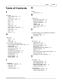
Table of Contents
1
Introduction
1
2
Installation
2
2.1
System Requirements
................................................................................................................................... 2
2.2
Software Installation
................................................................................................................................... 3
3
System Description
8
4
Getting Started
9
5
Main Menu
5.1
File Menu................................................................................................................................... 17
5.2
Setup Menu
................................................................................................................................... 26
5.3
Online Menu
................................................................................................................................... 36
5.4
Tools Menu
................................................................................................................................... 43
5.5
View Menu
................................................................................................................................... 43
5.6
Window Menu
................................................................................................................................... 44
5.7
Help Menu
................................................................................................................................... 45
6
How to Create a New DP Master
Project
46
Parameter Setting for QJ71PB93D
Slave Modules
62
8
I/O Mapping
64
9
Transfer Setup
69
10
Web-Based Online Access
81
11
Troubleshooting
96
7
Index
(c) 2006 MITSUBISHI ELECTRIC CORPORATION
16
100
1
1
GX Configurator-DP
Introduction
This manual...
...is a compact guide to using GX Configurator-DP software suitable both for beginners and
experienced users upgrading from other systems. The manual includes explanations of the terms
and structural concepts about the software and the configuration of an open network system. The
manual provides a precise step-by-step description of how to use GX Configurator-DP including
sample projects. These executable application is used to demonstrate the operation of the
program with the help of the examples provided in this manual. The PLC series MELSEC Q
Series is designated as MELSEC system Q in this manual.
If you are not yet familiar with MS Windows...
... please at least read the Windows Fundamentals section in the Windows User's Guide, or work
through the Windows Tutorial accessible through the Help menu of the Windows Program
Manager. This will teach you what you need to know about using the basic elements of Microsoft
® Windows, and the operating procedures that are identical in all Windows application programs.
If you have problems with parameter settings, ...
... please refer to the user´s manuals of the concerning open network modules.
If you get stuck...
... do not despair, help is never far away! If you run up against seemingly insoluble problems, or if
you have questions about GX Configurator-DP or the connected programmable logic controller
(PLC) configuration, please first refer to the manuals and documentation. Many answers and
solutions can also be found directly in the GX Configurator-DP context-sensitive online help
system, which can always be accessed by pressing the <F1> key. Make use of the Index
command in the Help menu as well, as this will often locate the information you need. If you
cannot find answers to your questions in any of these places, contact your local MITSUBISHI
ELECTRIC representative or call our European headquarters in Ratingen directly. The addresses
and phone numbers are provided on the back covers of all our manuals.
(c) 2006 MITSUBISHI ELECTRIC CORPORATION
Installation
2
2
Installation
Before You Begin
Copyright
Important Notice:
This software is protected by copyright. By opening the distribution disks package
you automatically accept terms and conditions of the license agreement.
You are only permitted to make one single copy of the original distribution disks for your
own backup and archiving purposes.
Software Purpose
This software is a configuration utility software package which will be used to configure
PROFIBUS DP network interface modules of MELSEC System Q, QnA, A and FX series' PLCs
such as:
· PROFIBUS DP master interface A(1S)J71PB92D
· PROFIBUS DP master interface QJ71PB92D
· PROFIBUS DP V1/V2 master interface QJ71PB92V
· PROFIBUS DP V1 master interface FX3U-64DP-M
· PROFIBUS DP slave interface QJ71PB93D
General Features
This software package has the following features:
· editor windows
· network parameter checking functions
· download and verify possibilities to the network modules
· parameter file handling on floppy disk / hard disk
· parameter print feature
· screen resolution independent
2.1
System Requirements
To install the GX Configurator-DP software package, your computer has to meet the following
requirements
Minimum Hardware Requirements
·
·
·
·
·
·
·
·
·
Pentium II 350 processor
32 MB RAM for Microsoft ® Windows 98/Windows Me
64 MB RAM for Microsoft ® Windows NT 4.0, Windows 2000
128 MB RAM for Microsoft ® Windows XP
VGA compatible graphics adapter
17"/43 cm diag. VGA monitor
At least 200 MB free hard disk space
CD-ROM drive
interface for communication with the PLC system
Software Requirements
GX Configurator-DP is a 32-bit software that runs on the following operating systems
· Microsoft ® Windows 98 or Windows Me (at least Microsoft ® Internet Explorer 5.5
installed)
· Microsoft ® Windows NT 4.0 ( Service Pack 6 or later and at least Microsoft ® Internet
Explorer 5.5 installed)
· Microsoft ® Windows 2000 (Service Pack 2 or later installed)
· Microsoft ® Windows XP Home or Professional Edition
(c) 2006 MITSUBISHI ELECTRIC CORPORATION
3
GX Configurator-DP
Note:
It is recommended to use Microsoft ® Windows 2000 or Windows XP.
On all operating systems with the exception of Microsoft ® Windows XP, Microsoft ®
Internet Explorer 5.5 must be installed.
2.2
Software Installation
GX Configurator-DP Setup
To install the GX Configurator-DP software from CD-ROM under Microsoft ® Windows
98/Windows Me or Windows NT/Windows 2000/Windows XP, you need to have Microsoft ®
Windows installed properly. You will need administrator privileges when installing the software.
If an old version of GX Configurator-DP is already installed, uninstall it first. After the
de-installation please start the installation of the new version. If you want to keep the older version
of GX Configurator-DP please select a different directory and program folder for the new version
of GX Configurator-DP. If the newer version is installed over the older version into the same
directory, this will cause problems with the old entries in the Start/Programs menu. A
de-installation of the older GX DP version, after the newer version has been installed, will also
damage the newer version. Therefore if you want to correct problems with the older entries please
reinstall new version after uninstalling both the older and the newer GX Configurator-DP versions.
Please close all other running software before installation and do not run other installation
programs during the installation of the GX Configurator-DP software.
Installing GX Configurator-DP/GX Configurator-ST
To start the installation, proceed as follows:
1. Insert the installation CD-ROM into your CD-ROM drive.
2. On the Desktop select the Start menu and open a Command Shell with the Run...
command.
3. Enter: d:\setup.exe (for "d:" enter the drive letter of YOUR CD-ROM drive).
4. The language selection screen appears. Choose the application language.
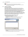
5. Follow the given instructions that guide you through the installation procedure. Continue
with Next >.
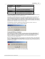
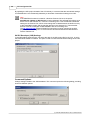
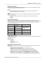
6. The licensing agreement is displayed. Please read these terms carefully and click Yes, if
you agree with the licensing agreement, or No,if you want to abort.
(c) 2006 MITSUBISHI ELECTRIC CORPORATION
Installation
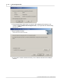
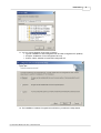
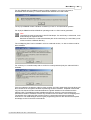
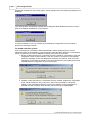
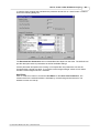
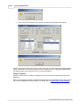
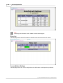
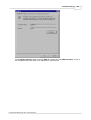
7. Enter your name, company and the product serial number. Click on Next > to proceed.
8. Check the registration information you have provided. Click on Yes to proceed with the
installation
(c) 2006 MITSUBISHI ELECTRIC CORPORATION
4
5
GX Configurator-DP
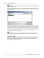
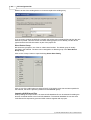
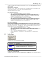
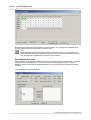
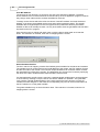
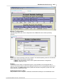
9. Enter the destination folder where you want the GX Configurator-DP software to be
installed. (Default C:\Melsec\GX Configurator-DP ). If you agree with the default setting,
just click on Next >.
10. If you want to install to a different directory click on Browse and select the installation
directory.
(c) 2006 MITSUBISHI ELECTRIC CORPORATION
Installation
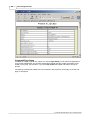
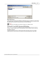
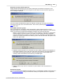
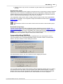
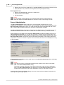
11. You can choose between three types of setups:
· Typical: installation of GX Configurator-DP and GX Configurator-ST (default)
· Compact: installation of GX Configurator-DP only
· Custom: select, whether to install GX Configurator-ST
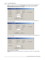
12. The installation is started. Progress bars will inform you about the setup status.
(c) 2006 MITSUBISHI ELECTRIC CORPORATION
6
7
GX Configurator-DP
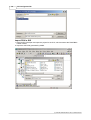
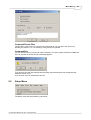
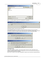
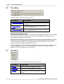
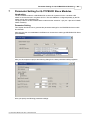
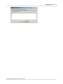
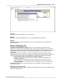
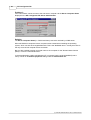
13. After the installation, you will see an appropriate message.
Button Functions
With the Next button you will leave the current menu and enter the next menu.
With the Back button you go to the previous window.
Cancel button ends the installation procedure.
(c) 2006 MITSUBISHI ELECTRIC CORPORATION
System Description
3
8
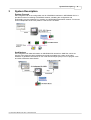
System Description
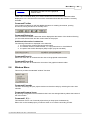
System Concept
GX Configurator-DP is the configuration tool for PROFIBUS interfaces in MITSUBISHI PLCs. It
provides functions for defining a PROFIBUS network, validating the configuration and
downloading it to the respective PLC module via a MITSUBISHI automation network. For remote
access independent of the user platform a web server is included.
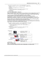
Architecture
GX Configurator-DP takes information on PROFIBUS DP slaves from GSD files, which are
specific to the respective slave module and typically provided by the vendor of the slave
hardware. It generates information for use in GX IEC Developer (GID) in form of program code
and CPU parameters (autorefresh).
(c) 2006 MITSUBISHI ELECTRIC CORPORATION
9
4
GX Configurator-DP
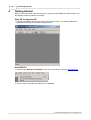
Getting Started
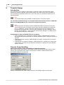
Below are the main steps, which are required to configure a PROFIBUS DP master module. The
QJ71PB92V module is used as an example.
Start GX Configurator DP
1. Start GX Configurator-DP via the shortcut in the Programs menu. The default is MELSOFT
Application/GX Configurator DP/GX Configurator DP.
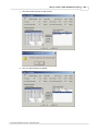
Add GSD File
1. Select the item GSD Device-Database in the main menu Setup to open the GSD Database.
2. Click on <Add> to add the new GSD file to the database.
(c) 2006 MITSUBISHI ELECTRIC CORPORATION
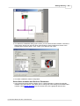
Getting Started
3. Select the GSD file, which should be added to the database, and confirm with <Open>.
Start a New Project
1. In the main menu File select New to open a new project file.
2. Select the type of master module, which you want to configure.
(c) 2006 MITSUBISHI ELECTRIC CORPORATION
10
11
GX Configurator-DP
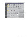
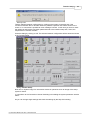
3. When you have clicked on <OK> a new project file is opened in the graphical network editor
showing the selected type of PROFIBUS master module.
Add Slave to the Network
1. In the graphical network editor press the right mouse button to open the context menu. Select
the menu item Insert DP-Slave from the context menu to add a slave.
(c) 2006 MITSUBISHI ELECTRIC CORPORATION
Getting Started
12
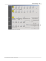
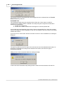
2. The GSD device database dialog opens where you can select the slave module. Choose the
Slave Device Group from the drop down list and select a slave module from the list of the
available slave systems below. Then confirm your selection with <OK>.
3. The slave is added to master configuration.
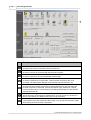
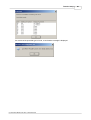
Select Slave modules and Set User Parameters
1. In the 'Slave Parameter Settings' dialog click on <Select Modules> to select the modules
installed in the slave device. If you later want to change the slave settings and installed slave
modules, select Modify Settings from the context menu of the graphical network view.
(c) 2006 MITSUBISHI ELECTRIC CORPORATION
13
GX Configurator-DP
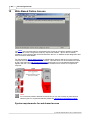
2. Select the modules, which are installed in the slave device, in the left list and add them to the
list of installed modules by pressing <Add before> or <Add after>. The sequence of modules in
the 'Installed Modules' list must usually equal the sequence of modules within the slave device.
To delete a module from this list, mark the entry and press <Remove>.
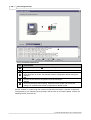
Configure Connection to PLC
1. To configure a transfer connection to the PLC select Online->Transfer Setup from the main
menu. You can either configure the default transfer setup or define a new one.
(c) 2006 MITSUBISHI ELECTRIC CORPORATION
Getting Started
14
Download Configuration to Master
1. Select Online -> Transfer -> Download to Module in the main menu to download the
configuration to the master module.
Create POU
1. To create the program code for GX IEC Developer, which assists with access to PROFIBUS I/O
select File -> Export -> POU for GX IEC Developer.
2. Select the path for the GID ASCII file.
(c) 2006 MITSUBISHI ELECTRIC CORPORATION
15
GX Configurator-DP
Import POU in GID
1. Start GX IEC Developer and open the project for the PLC, which accesses the PROFIBUS
master module.
2. Import the ASCII file generated by GXDP.
(c) 2006 MITSUBISHI ELECTRIC CORPORATION
Main Menu
5
16
Main Menu
Starting GX Configurator-DP
Select GX Configurator-DP from the Windows Start menu. The default shortcut is
Start/Programs/MELSOFT Application/GX Configurator-DP
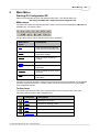
Main menu
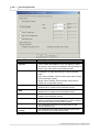
The main menu offers the following pull-down menus. The menu items Online and Window are
available only, if a project is open.
The pull-down menus can be selected via mouse or keyboard.
Main Menu
Items
Description
File
menu for opening and printing
project files and exporting POUs
Setup
menu for configuration and
application settings
Online
menu for online access to a
module
Tools
menu for external tools
View
menu for configuration of the
application
Window
menu for listing the open project
windows
Help
menu for help and application
information
The items in the open pull-down menus can be reached via mouse or keyboard. The underlined
character will start the function. In addition there are some menu items which may be started
using predefined hotkeys.
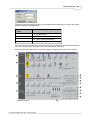
Toolbar items
The toolbar just below the main menu contains buttons for an instant access of the most
frequently used functions of GX Configurator-DP:
Command
Description
New
Starting a new project
Open
Opening an existing project
Save
Saving a modified project
Print
Printing the current project
Page Setup
Defining the parameters to be printed
(c) 2006 MITSUBISHI ELECTRIC CORPORATION
17
5.1
GX Configurator-DP
Command
Description
Transfer
Setup
Defining the network connection type (PC to
PLC)
MXChange
MXChange support properties
GSD
GSD device database
Help
Getting context help
Help Tool
Getting help on items you click on
About
Displaying program information
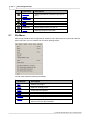
File Menu
After having started the GX Configurator-DP software, this is the first menu to work with. With the
help of this menu you can create a new or load an existing project.
The File menu offers the following commands:
Command
Description
New
Starts a new project.
Open
Opens an existing project.
Close
Closes the active project.
Save
Saves a modified project.
Save As
Saves a modified project under a new name.
Export
Saves configuration as a configuration image or creates a
POU for use in GX IEC Developer.
(c) 2006 MITSUBISHI ELECTRIC CORPORATION
Main Menu
Command
Description
Change Master
Type
Changes the current project to a different type of master
module.
Print
Prints the project.
Page Setup
Specifies the page layout and selects parameters for
printouts.
Recent Files
Opens one of the latest used projects.
Exit
Ends GX Configurator-DP.
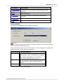
Command New
The menu command New is used to create a new project.
Note:
No default module type is selected. Choose the target PLC family and a supported
module type before continuing.
First you have to select the type of module, which you want to configure. The modules are
grouped by the PLC family, they can be used with.
CPU Series
Available Modules
Qn
QJ71PB92D (PROFIBUS DP V0 Master)
QJ71PB92D – Mode 0 (PROFIBUS DP V0 Master)
QJ71PB92V (PROFIBUS DP V1/V2 Master)
QJ71PB93D (PROFIBUS DP V0 Slave
QnA/A
A(1S)J71PB92D (PROFIBUS DP V0 Master)
A(1S)J71PB92D – Mode 0 (PROFIBUS DP V0
Master)
FX
FX3U-64DP-M (PROFIBUS DP V1 Master)
Then the graphical network editor appears
(c) 2006 MITSUBISHI ELECTRIC CORPORATION
18
19
GX Configurator-DP
Here you edit the dedicated parameters for the selected network interface module in specific
editors.
At present the A(1S)J71PB92D, QJ71PB92D, QJ71PB93D, QJ71PB92V and FX3U-64DP-M
PROFIBUS DP network interfaces are supported.
The following parameters can be edited:
· Master Settings
· Bus Parameters
· Slave Parameter Settings
Command Open
The menu command Open allows to open a project, which has previously been saved. This
command uses the Windows dialog box for file open operation.
(c) 2006 MITSUBISHI ELECTRIC CORPORATION
Main Menu
20
The Open dialog box lists only files of the following type:
· *.DP2: project for a master module configuration
· *.DPX: project for a QJ71PB93D slave module configuration
The shortcuts defined by the Windows dialog box for file open are valid.
Compatibility to Older Versions
Open previous project files in GX Configurator-DP 7.01B according to the following table
File
type
Software version
*.dp2
ProfiMap 3.0
GX Configurator-DP 4.00
GX Configurator-DP 4.01A
GX Configurator-DP 4.02C
GX Configurator-DP 5.00A
GX Configurator-DP 5.01B
GX Configurator-DP 6.00A
GX Configurator-DP 6.01B
GX Configurator-DP 6.02C
GX Configurator-DP 7.00A
*.dpx
GX Configurator-DP 5.00A
GX Configurator-DP 5.01B
GX Configurator-DP 6.00A
GX Configurator-DP 6.01B
GX Configurator-DP 6.02C
GX Configurator-DP 7.00A
Previous versions cannot open GX Configurator-DP 7.01B project databases.
Note:
*.DP-projects generated with software versions previous to MELSEC ProfiMap V. 3.0
cannot be opened.
Command Close
This menu command closes the active project.
Command Save
This menu command is used to save a modified project. The project will be saved to the assigned
file name. If no file name exists (e.g. new project) the standard dialog box for Save as will be
opened.
Two different file types are used:
· *.DP2: project for a master module configuration
· *.DPX: project for a QJ71PB93D slave module configuration
Command Save As
(c) 2006 MITSUBISHI ELECTRIC CORPORATION
21
GX Configurator-DP
This menu command is used to save a modified project with a new assigned file name. This
command uses the dialog box for file saving.
The file extension *.DP2 or *.DPX is appended automatically depending on the module type you
selected.
Command Export
This menu command opens another submenu in which the user can choose between generating
PLC program code or saving the configuration image to file for a download to the master with a
different tool.
POU for GX IEC Developer
This function generates PLC program code for GX IEC Developer (GID), which assists the
application programmer in accessing the I/O data cyclicly transferred via PROFIBUS. The type
and contents of the generated code depend on the type of the master module.
For A(1S)J71PB92D and QJ71PB92D in operating mode E as well as for QJ71PB92V modules
an ASCII file and a user library are generated by GXDP in the given directory. The ASCII file
contains the task definition and the reference to the user library. The user library contains the DUT
definitions, global variable declarations and program instructions for I/O mapping. When
importing the ASCII file into a GID project, the user library is automatically imported as well.
For FX3U-64DP-M master modules the 'Copy POU' or the 'I/O Mapping POU' can be generated.
The 'I/O Mapping POU' contains global variables for access to PROFIBUS I/O. It does however
not ensure data consistency. This is only done by the 'Copy POU'.
All slaves in the project are checked whether they require consistency. If a slave requires
consistency, the user is informed and can only generate the 'Copy POU'.
If consistency is not required, the user can choose for an FX3U-64DP-M master between the
normal 'Copy POU' or the 'I/O Mapping POU'.
(c) 2006 MITSUBISHI ELECTRIC CORPORATION
Main Menu
22
For QJ71PB92D and QJ71PB92V master modules consistency can only be ensured, if
autorefresh with consistency is used for data transfer between CPU and master.
The A(1S)J71PB92D master maintains consistency in both A- and QnA-series systems.
For A(1S)J71PB92D and QJ71PB92D in operating mode 0 no POU can be generated.
Note:
The ASCII file must be imported in GX IEC Developer. If a user library is referenced, it will
automatically be imported as well.
Because the ASCII file contains the absolute path of the user library, the user library must
not be moved to a different directory.
The 'I/O Mapping POU' can be created in a full or a reduced version, i.e. with or without code for
slave modules.
For A-CPUs (i.e. a transfer setup with an A-CPU is currently selected) only the reduced POU is
available.
If the user selects to include the code for slave modules, the POU respectively the user library will
also contain DUTs and global variables representing the slave modules. Separate networks will
copy the I/O data of the slave modules between the global variables of the modules and the
transfer buffer. The additional global variables and devices, which the user has assigned to
individual I/O areas of modules, are also only included in the full version of the I/O mapping POU.
The benefits of the reduced POU are lower memory consumption and less programming
instructions. The disadvantages are the higher programming effort for the user and the required
knowledge on the I/O structure of the slaves.
(c) 2006 MITSUBISHI ELECTRIC CORPORATION
23
GX Configurator-DP
Note:
The detailed I/O data structures for ST1H-PB slave modules are only available in the full
version of the POU.
The user can select the directory and the name of the POU ASCII file. The file name must start
with a letter and not have more than 16 characters. The file name is used as name for user library
and program as well.
If a user library is generated as well, it is located in the same directory, but with the extension '.sul'
instead of '.asc'. Additionally to the .sul file the contents of the user library are saved in an ASCII
file with the extension '.sul.asc'. This file should not be imported in GID. Its purpose is to allow the
user to view the contents of the user library without importing and opening the user library in GID.
The title of the file dialog shows the CPU type, for which the POU is generated. This is the CPU
type set in the currently selected transfer setup.
Note:
If the PROFIBUS master is located in a Q-series 'Remote I/O' rack, the POU must be
imported in the GID project for the controlling PLC, not the project of the 'Remote I/O'
rack.
Configuration Image
With this menu command the user is prompted for a file path to store the configuration image,
which is generated from the current project. The configuration image contains the binary encoded
structure of master and slave parameters as they are stored in the master. Its contents are
therefore specific for the type of the master.
(c) 2006 MITSUBISHI ELECTRIC CORPORATION
Main Menu
24
Command Change Master Type
With this menu item the user can change the current project to a different operating mode or to a
different type of master module.
Command Print
This command is available for master projects only. It creates an HTML document containing the
settings of the current project and displays the document in the default web browser. Detailed
appearance of the printout depends therefore on the browser. Via the browser menu the settings
can be printed or saved for documentation purposes. The information about what is to be printed
is set via Page Setup.
(c) 2006 MITSUBISHI ELECTRIC CORPORATION
25
GX Configurator-DP
Command Page Setup
Available for master projects only. When you choose Page Setup you can select the parameters
to be printed. Additionally you can enter a descriptive header text and select the position of the
header on the page: top or bottom. If you select No header the header information will not be
printed.
The settings including the header text are not stored in the project file, but locally on the PC and
apply to all projects.
(c) 2006 MITSUBISHI ELECTRIC CORPORATION
Main Menu
26
Command Recent Files
The pull-down menu shows you the last four used projects. You can open one of them by
pressing the shortcut 1 to 4 or selecting it using mouse or keyboard.
Command Exit
You can use this menu command to quit the software. If an open project has been modified and
has not yet been saved the following message appears:
If you want to save the last changes before leaving and terminating the GX Configurator-DP
software choose <Yes> .
If you choose <No> all modifications are lost.
5.2
Setup Menu
The Setup menu offers the following commands:
(c) 2006 MITSUBISHI ELECTRIC CORPORATION
27
GX Configurator-DP
Command
Purpose
MXChange Support
setup of the properties of the MXChange
connection
GSD Device
Database
access to the GSD device database
PLC and GX IEC
Developer (GID)
Settings
opens a dialog with tab pages, which allow to
configure the data exchange between PROFIBUS
master and PLC CPU
Options
opens a dialog in which the user can change
settings related to the GSD database
Command MXChange Support
Available for *.DP2 projects only. MXChange is an external software package made by Mitsubishi
Electric. An A(1S)J71PB92D or QJ71PB92D PROFIBUS DP project can use MXChange to export
information for MELSOFT GX IEC Developer or MELSEC MEDOC plus v2.32 or later. The
update is done automatically when the A(1S)J71PB92D or QJ71PB92D project is saved. For this
purpose the MXChange server must be installed and GX Configurator-DP must be connected to
this server.
This dialog is used to set up the MXChange connection
Command
Description
MXChange
Connection Usage
Local MXChange
Server
enable/disable MXChange function
specifies that MXChange is installed locally on
the same system as GX Configurator-DP (not in
LAN)
(c) 2006 MITSUBISHI ELECTRIC CORPORATION
Main Menu
Command
Description
Select Server
Instance
selects one of up to 16 available servers to
connect to
IP Address
specifies the IP address of the MXChange server
in LAN (ask your network administrator)
enter your user name for the MXChange server
enter your password for the MXChange server
tests, if a connection to the MXChange server
can be established with the specified settings
User Name
Password
Test
28
You can set the MXChange connection usage for the A(1S)J71PB92D or QJ71PB92D project by
enabling the MXChange Connection Usage check box.
If you prefer a local MXChange server, it is compulsory to install the server on the local PC. The
local MXChange server is selected by enabling the Local MXChange Server check box. For
correct remote MXChange support it is compulsory to install the TCP/IP services of the operating
system. The correct IP address of the remote station, where the server is located, can be set by
disabling the local MXChange server check box. The correct account consisting of user name and
password is also compulsory for remote connection usage.
If the MXChange connection is enabled and a project is saved for a master, which is not
supported by MXChange, a warning message is displayed.
Command GSD Device Database
The command is only available, if no project is currently open. However the GSD database only
effects .DP2 projects.The device database contains information about PROFIBUS DP slave
devices from Mitsubishi or 3rd party manufacturers. This item is used to add device information
stored in GSD files to the internal database and to import extracted GSD data from other
computers running GX Configurator-DP.
Because changes to slave types, which are used in any currently open project, may impact these
projects, the GSD database can only be modified, if no project is open. Therefore the following
message box will be displayed, when trying to open the dialog with a project currently opened. So
first close all open projects.
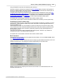
The Device Database can be modified in the following dialog
(c) 2006 MITSUBISHI ELECTRIC CORPORATION
29
GX Configurator-DP
When a group is selected in the box ”Slave Device Group”, the model names of the devices
belonging to the selected group are displayed in the lower list box ”Available Slave Systems”.
Upon selecting a device entry in this list box the bitmap, which has been assigned to the device, is
displayed on the right side of the list box.
By double-clicking on the bitmap display or using the button "Replace Bitmap", a file dialog is
opened, in which a file with a new bitmap can be selected. Via the group of radio buttons the type
of bitmap that is replaced can be selected. The GSD standard specifies bitmaps for:
· normal operation (this is used in the GX Configurator-DP editor)
· diagnostic status
· special operations mode
Beneath the bitmap both vendor name and revision string are displayed, as well as the name of
the GSD file and the bitmap file. The so called GSD file describes the features of the slave such
as the supported baud rate and the slave structure (modular slave/compact slave). The displayed
vendor name and revision are included in the GSD file as well.
Please ask the manufacturer of the slave device for the matching GSD file.
Adding Devices
A slave device can be added to the database by pressing the <Add> button. A file dialog appears
to select the GSD file. When leaving the dialog with <Ok>, the GSD file is parsed and its contents
stored in the local GSD device database. The GSD file itself is no longer required. If the GSD file
references a bitmap file for the slave device GX Configurator-DP automatically tries to load the
respective bitmap file and store it in the GSD database. In case the file is not found a default
bitmap is used instead. This can lateron by replaced with a device specific bitmap.
The PROFIBUS standard specifies the following format for the bitmap file:
Width
70 pixels
Height
40 pixels
Colors
16
(c) 2006 MITSUBISHI ELECTRIC CORPORATION
Main Menu
File Extension
30
dib, bmp
Only bitmaps that match the requirements in the table above should be used. Other bitmaps with
other sizes and color depths can be used, but will cause a warning message
When both GSD and bitmap file have been selected, you will be asked to confirm the operation.
If you confirm, the contents of both files are read in and an entry is added to the internal device
database for that device. Thereafter, you do not need the actual GSD and bitmap files any more.
Updating DPV1 Slave Settings
Some slaves, which support the alarm handling of DPV1, but not acyclic read/write, do not include
the DPV1_Slave keyword in their GSD file. Therefore the user is asked after parsing the GSD file,
whether the slave supports the DPV1 format for parameter encoding. If <Yes> button is selected,
the GSD database is updated as if the GSD file would have contained the entry DPV1_Slave=1.
GSD Update
If you try to add a GSD file to the device database for a device, which already exists, a warning is
shown. You can either choose to add the device information with a device revision or type name
(c) 2006 MITSUBISHI ELECTRIC CORPORATION
31
GX Configurator-DP
different to that of the existing device or choose to replace the existing entry.
If you choose to replace the GSD file, internally the existing entry is deleted first and then the new
GSD file is parsed. This will however not effect existing projects, which already use the device
type and where the GSD information is part of the project file.
Slave Device Group
DP slaves are grouped in one of the so-called ‘slave families’. The default group is usually
specified in the GSD file. The slave can be assigned to a different group in the Slave Device
Group dialog.
Click on the <Group> button to open the dialog Select Slave Family.
Click on one of the radio buttons to select a family. If the device group has not been specified in
the GSD file, the slave is placed by default into the ‘General’ group.
Importing GSD-Extract Files
When pressing the 'Import' button, an external GSD database file can be selected for adding the
devices contained therein to the local GSD database. The external database file can also be a
'GSD Extract' file exported by previous GXDP versions together with a project.
(c) 2006 MITSUBISHI ELECTRIC CORPORATION
Main Menu
32
Removing devices
A device can be removed from the database by selecting the entry in the left list box and pressing
the <Delete> button. This deletes only the entry in the GSD database. It does not delete the GSD
and bitmap files for that device. These files have to be removed manually.
Note:
The entry is immediately removed after clicking on the <Delete> button.
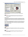
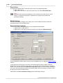
Command PLC and GX IEC Developer (GID) Settings
With the menu command PLC and GX IEC Developer (GID) Settings the user can view and
change the settings related to the PLC and GID project, which the master module is used with.
CPU Device Access
In the tab ‘CPU Device Access’ the data transfer between the buffer memory of the master
module and the PLC device memory is configured. The following table lists the input fields.
(c) 2006 MITSUBISHI ELECTRIC CORPORATION
33
GX Configurator-DP
Input Fields
Description
Slave Specific
Transfer
Buffer devices are assigned to each slave individually in the
column "Buffer MIT-Address" in the "I/O Mapping" dialog.
This option is only useful in combination with autorefresh or
for the 'Copy POU' of the FX3U-64DP-M master.
Block Transfer
The input as well as the output areas of all slaves are
transferred in a single step using one common transfer
buffer.
Input: device address, where the slave input data is copied
to from the buffer memory.
Output: device address, where the slave output data is
copied from to the buffer memory.
Comm. Trouble Area
Device address, where the so-called ‚Communication
Trouble Area’ is copied to from the buffer memory
Extd. Comm. Trouble
Area
Device address, where the so-called ‚Extd. Communication
Trouble Area’ is copied to from the buffer memory
Slave Status Area
Device address, where the so-called ‚Slave Status Area’ is
copied to from the buffer memory
Data Transfer using...
Select, whether TO/FROM instructions or autorefresh is
used for exchanging the data between PLC device memory
and the buffer memory of the master module
Copy Instructions
Use TO/FROM instructions (for all PLC series except
Q-series 'Remote I/O')
AutoRefresh (Update
of CPU)
Use autorefresh and update of the settings online on the
CPU (Q-series only except 'Remote I/O')
(c) 2006 MITSUBISHI ELECTRIC CORPORATION
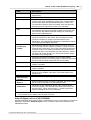
Main Menu
Input Fields
Description
AutoRefresh (Update
of GID project)
Use autorefresh and update the settings offline in the
corresponding GID project or the selected autorefresh
settings file (usually named 'iparam.wpa')
34
For transferring the slave I/O data, there is a choice of two different methods:
Slave Specific Transfer: each input and output area of a slave can be mapped to a separate
device address. This type should not be used in combination with the I/O mapping POU because
it increases the time for data exchange between PROFIBUS master and PLC CPU. It is mainly
provided for compatibility with previous versions in combination with autorefresh and for use with
FX master modules. The device addresses are assigned in the I/O mapping dialog.
Block Transfer: the complete inputs and outputs of all slaves are transferred to and from a single
device area in the CPU. This requires a larger contiguous memory area in the CPU, but saves
transfer time and autorefresh entries, if used in combination with autorefresh. It is the preferred
mode for use with I/O mapping. The device addresses for the input and output buffer must be set.
Note:
When using ‘Slave Specific’ transfer in combination with autorefresh, the total maximum
of 256 autorefresh entries per PLC CPU may be exceeded, when a large number of
slaves is used. Each input and each output area of a slave requires a separate
autorefresh entry.
Additionally to the I/O data the buffers containing diagnostic and status information can be
mapped to a device area in the CPU. For information on the contents of these buffers please
consult the manual of the respective master module.
The data is transferred between module buffer memory and CPU devices using TO/FROM
instructions, which are included in the PLC program code exported by GXDP. For Q-series PLCs
there is the additional option of autorefresh transfer. Autorefresh is supported for both slave
specific as well as block transfer mode. The advantages of the use of autorefresh are the faster
data exchange, data consistency and that there is no influence on the PLC cycle time. It is
configured via a parameter file on the PLC CPU.
Copy Instructions
The output transfer buffer at the user specified device address is copied to the buffer memory with
one (for ‘Block Transfer’) or several (for ‘Slave Specific’) TO instructions. In the opposite direction
the inputs are transferred with one or more FROM instructions from the buffer memory to the input
buffer device specified by the user. With the exception of the 'Copy POU' for the FX master 'Block
Transfer’ should be used in combination with TO/FROM instructions.
AutoRefresh (Update of CPU)
Note:
Available for Q-series only !
If selected, the autorefresh settings are updated online in the CPU after downloading the
configuration to the master module. The CPU must be stopped during the autorefresh update.
AutoRefresh (Update of GID Project)
Note:
Available for Q-series only !
If selected, the autorefresh settings are either updated in the autorefresh parameter file in the
corresponding GID project, or, if no GID project has been assigned, in the file specified by the
user.
(c) 2006 MITSUBISHI ELECTRIC CORPORATION
35
GX Configurator-DP
By updating the GID project instead of the CPU directly it is ensured that the autorefresh settings
for PROFIBUS are not accidentally deleted by a download of autorefresh settings from GID.
Note:
If the PROFIBUS master is located in a Q-series 'Remote I/O' rack, the option '
AutoRefresh (Update of GID Project)' must be selected. The selected GID project must
be the one for the 'Remote I/O', not for the controlling CPU. This will add the autorefresh
settings to the 'Remote I/O', which will exchange the I/O data between the buffer memory
of the PROFIBUS master and the transfer devices in the 'Remote I/O'. These transfer
devices must be exchanged via MELSECNET with the controlling CPU.
The I/O mapping POU (without FROM/TO instructions) must be imported in the GID
project for the controlling CPU. It will access the devices transferred via MELSECNET
with the 'Remote I/O'.
GX IEC Developer (GID) Settings
In the GID settings page the user can select the path of the GID project file for the PLC, in which
the PROFIBUS master is installed. This path is used to locate the autorefresh settings of the GID
project.
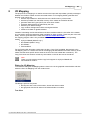
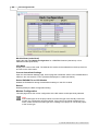
Command Options
Change settings related to the GSD database. This command opens the following dialog providing
access to different options.
(c) 2006 MITSUBISHI ELECTRIC CORPORATION
Main Menu
36
To apply the updated GSD database to an existing project the option GSD database has priority
must be enabled.
GSD database has priority
This option controls, whether GSD information in the project file, if present, is overwritten by the
corresponding information from the GSD database for the same types.
This option has the following effects:
When opening a project file
· Case 1: The option GSD database has priority is selected
GX Configurator-DP tries to locate the GSD information for the slave types, which are
used in the project, in the local GSD database. If the type cannot be found in the
database, it tries to find the information in the project file. If that fails as well, an error
message is displayed and the project cannot be opened.
· Case 2: The option GSD database has priority is not selected
GX Configurator-DP tries to locate the GSD information for the slave types, which are
used in the project, in the project file itself. If the type cannot be found in the project, it
tries to find the information in the local GSD database. If that fails as well, an error
message is displayed and the project cannot be opened.
When saving a project file
When a project is saved, GXDP adds the GSD information for all slave types, which are used in
the project and for which the GSD information does not already exist in the project file, to the
project file. GSD information in the project file for types, which no longer are used in the project, is
removed from the project file. GSD information existing in the project file for types still in use, is
handled depending on the option 'GSD database has priority'.
· Case 1: The option 'GSD database has priority' is selected
If the GSD information for a certain type exists in both project file and local GSD
database, the GSD entries in the project file are deleted and replaced by those from the
GSD database.
· Case 2: The option 'GSD database has priority' is not selected
Existing GSD entries in the project file for types, which are still in use, will not be
changed.
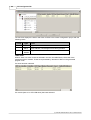
5.3
Online Menu
The Online menu offers the following commands:
Command
Description
Transfer Setup
defining the network connection type (PC to PLC).
Transfer
downloading the configuration from the current project to
the module specified by the current transfer setup.
Start/Stop
PROFIBUS
user can start and stop the cyclic DP data transfer.
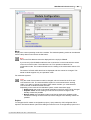
Command Transfer Setup
The dialog is started via the menu item Online/Transfer Setup. When a new project is created, a
(c) 2006 MITSUBISHI ELECTRIC CORPORATION
37
GX Configurator-DP
default transfer setup is automatically added to the project file. With the <Configure> button you
can change the settings both for the default and for a new created transfer setup.
For a more detailed description how to handle a transfer setup see also chapter Opening the
transfer setup and defining a network connection.
Command Transfer
In the submenu Transfer the user can choose between:
· Download to Module...: download the configuration from the current project to the
connected module.
· Verify: upload the existing configuration from the module and compare it with the current
project.
· Upload Config.Image: read the binary configuration image from the master and store it
in a file
· Download Config.Image: download the configuration image taken from the specified file
to the master module
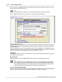
Command Download to Module…
This item downloads the configuration in the current project to the master module specified in the
transfer setup. The user must confirm the operation, before the download is actually started.
Note:
The FX3U-64DP-M PROFIBUS master can only be updated, if the CPU is stopped. The
CPU can be stopped and restarted automatically during the download, if the user agrees.
If the download has been successful and autorefresh is selected as data transfer method, the
user is asked, whether the autorefresh settings should be updated or not. Depending on the
selection in CPU Device Access either the CPU or a file is updated.
For other master modules than A(1S)J71PB92D the note about the mode switch is hidden in the
message box.
Note:
If you use a A(1S)J71PB92D module the user must set the correct operation mode (0 or
E) with the switch on the front of the module.The module will take over the setting of the
mode switch after a CPU reset.
(c) 2006 MITSUBISHI ELECTRIC CORPORATION
Main Menu
38
Download to project module type only
GXDP will allow a download only to the same module type as specified in the project. If the
module found in the specified slot of the target PLC rack does not match that of the project, an
error message is displayed.
If the user wants to download the project to a different module type, the project must first be
converted to the type of the connected module. This is done by selecting the Change Master
Type menu item.
For QnPRH redundant systems
If the connected PLC is a QnPRH, GXDP automatically checks whether both PLCs of the
redundant system are accessible by using the tracking cable and also checks the current backup
mode. The procedure for download is adapted according to the result of these tests
1. ‘Backup’ mode and both PLCs connected: the user is asked for confirmation to update both
master modules. If the user confirms, the system is automatically switched to ‘Separate’
mode and default device tracking is turned off. Then the configuration is downloaded to the
master in the control as well as in the standby system. After the download, the system is set
back to the original state.
2. ‘Separate’ mode and both PLCs connected: the user is asked, whether the configuration of
both master modules or only of the one in the locally connected PLC should be updated. In
both cases device tracking is turned off, while the configuration is downloaded to the
master(s). After the download, device tracking is enabled again.
3. ‘Debug’ mode or only one PLC connected: only the master in the connected PLC is
updated.
AutoRefresh Update
If the user has selected 'AutoRefresh (Update of CPU)' or 'AutoRefresh (Update of GID Project)' in
the 'PLC and GID Settings' dialog, the autorefresh settings are updated, after the configuration
(c) 2006 MITSUBISHI ELECTRIC CORPORATION
39
GX Configurator-DP
has been successfully downloaded to the PROFIBUS master module.
AutoRefresh (Update of CPU)
The (online) update of the autorefresh settings on the CPU is only possible, if the CPU is stopped.
The CPU status is checked and, if the status is not 'Stopped', the user is asked, whether the CPU
can be stopped.
After stopping the CPU the autorefresh settings on the CPU are updated. Existing autorefresh
settings on the CPU for the same head address as the current master module are overwritten with
the settings for the master, existing settings for other modules remain unchanged.
If the CPU had been stopped prior to the update, the user is asked whether to start the CPU
again.
AutoRefresh (Update des GID Project)
The (offline) update of the autorefresh settings in the parameter file of a GID project is done
automatically, if the path to an existing GID project directory has been set. Otherwise the user is
prompted for the path of the parameter file, which should be updated.
(c) 2006 MITSUBISHI ELECTRIC CORPORATION
Main Menu
40
After a successful update, the path of the updated file is displayed.
AutoRefresh Update of Q-series 'Remote I/O' CPU
If the PROFIBUS master is located in the rack of a Q-series 'Remote I/O' CPU, the options
'AutoRefresh (Update of CPU)' and 'Copy Instructions' are not possible for data transfer. The user
is informed and offered to update the autorefresh settings in a GID or GD project instead.
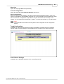
Command Verify
This function verifies the settings of the selected project with the current configuration of the
module. For PB92D masters a warning is displayed to inform the user that the data exchange on
the PROFIBUS network will be stopped.
Click <OK> to continue. The current configuration is read from the module and compared with the
(c) 2006 MITSUBISHI ELECTRIC CORPORATION
41
GX Configurator-DP
configuration created from the current project. If both settings match, the following message box is
displayed.
If the settings differ, the following message box is displayed. More detailed information on which
parts of the settings are different, is not provided.
In case any problems occur, for example when reading the configuration from the module, a
general error message is shown.
For QnPRH redundant systems
If the connected PLC is a QnPRH, GXDP automatically checks whether both PLCs of the
redundant system are accessible by using the tracking cable and also checks the current backup
mode. The procedure for verify is adapted according to the result of these tests
1. ‘Backup’ mode and both PLCs connected: the user is asked for confirmation to verify the
configuration of both master modules. If the user confirms, the system is automatically
switched to ‘Separate’ mode and default device tracking is turned off. Then the current
configuration is read from the master in the control as well as in the standby system and
compared with the configuration of the current project..
2. ‘Separate’ mode and both PLCs connected: the user is asked, whether the configuration
of both master modules or only of the one in the locally connected PLC should be
verified. In both cases device tracking is turned off, while the current configuration is
uploaded from the master(s). After the verify, device tracking is enabled again.
(c) 2006 MITSUBISHI ELECTRIC CORPORATION
Main Menu
42
3. ‘Debug’ mode or only one PLC connected: only the master in the connected PLC is
checked.
Upload Config. Image
GXDP tries to connect to a master module of the type set in the current project, using the selected
transfer setup. If the connection is established, the current configuration is read from the master
module and stored in binary format in the file, which the user has selected. Information stored in
the PLC CPU like autorefresh settings or POU code is not retrieved.
The configuration image can be used to configure another master module, if the original GXDP
project file is not available. The configuration image is downloaded a master with the 'Download
Config. Image' function.
Note:
The information read from the master module cannot be used to create a GXDP project
file.
Download Config. Image
The user must first select a file with configuration image created by a previous upload ( see
'Upload Config. Image' ) or the corresponding export function of GXDP (see 'Export -> Config.
Image' ). This configuration must be compatible to the module type set in the current project.
GXDP tries to connect to the master module, using the selected transfer setup. If the connection
is established, the configuration image is written to the master module.
Command Start/Stop PROFIBUS
This item is used to manually start or stop the PROFIBUS DP cyclic data transfer of DPV0.
The current status of the connected PROFIBUS master is checked. If there is no active data
transfer, the user is asked to confirm starting the transfer.
If the data transfer is active, the user is asked to confirm stopping the transfer.
The cyclic data transfer is started and stopped by setting respectively resetting the Y0 (+ starting
I/O number) device of the master. If a PLC program, which starts the data transfer, is running,
while the user tries to stop the data transfer, the operation fails. An error message is displayed
and the user is informed of the possible access conflict between PC and PLC program.
(c) 2006 MITSUBISHI ELECTRIC CORPORATION
43
5.4
GX Configurator-DP
Tools Menu
The Tools menu offers the following commands:
Command
Description
Server Administrator
starts a web server for online access to the
modules.
GX Configurator
Client
client for logging in to the web server for online
access to the modules.
GX Configurator-ST
starts GX Configurator-ST for configuration of
ST1H-PB 'Slice I/O' slaves
Starting GX Configurator-ST
The menu command GX Configurator-ST is used to start the configuration tool for the ST modules
(Slice Terminal). This menu command is enabled, if GX Configurator-ST is installed, i.e. the
corresponding executable file can be found.
With the GX Configurator-ST you can operate settings and monitor ST1H-PB graphically. It shows
various status of ST1H-PB and slice modules, which include error information. You are able to
use the forced output function via GX Configurator-ST and easily check your wirings. You can
also set parameters of intelligent modules of ST series.
The GX Configurator-ST runs as a separate application with its own entry in the task list and must
be closed separately. However, when GX Configurator-DP is closed, it displays a warning
message in case GX Configurator-ST is still running.
5.5
View Menu
In the View menu you can select the following menu commands:
Command
Description
Toolbar
Shows or hides the application’s toolbar.
Status Bar
Shows or hides the application’s status bar.
Zoom In
Increases the view size of the graphical network
editor.
(c) 2006 MITSUBISHI ELECTRIC CORPORATION
Main Menu
Zoom Out
44
Decreases the view size of the graphical
network editor.
These menu commands allow you to select whether the tool bar and the status bar will be
displayed or not. A check mark in front of the commands shows that this function is currently
activated.
Command Toolbar
If the toolbar is enabled you will find additional buttons for creating documents, opening
documents, saving documents or the help menu.
Command Status bar
If this command is enabled a status bar will be displayed at the bottom of the window informing
you about the selected item and the current status of the project.
Additional information in status bar
The following information is displayed in the status bar
1. the name of the currently selected transfer setup
2. the method used for I/O data transfer, i.e. 'Copy Instructions' or 'AutoRefresh'
3. the path of the GX IEC Developer (GID) Project (may be truncated)
Command Zoom In
Select this menu item to increase the view size of the graphical network editor.
Command Zoom Out
Select this menu item to decrease the view size of the graphical network editor.
5.6
Window Menu
This menu provides the standard "window" functions
Command Cascade
The user can arrange all open project windows so that the overlap by selecting the menu item
cascade.
Command Arrange Icons
By selecting arrange icons all minimized window icons are arranged side by side at the bottom of
the main window.
Command 1,2,3,...
This switches over to one of several projects that you keep open simultaneously.
Either click on the loaded project you want to switch to or enter the according number.
(c) 2006 MITSUBISHI ELECTRIC CORPORATION
45
5.7
GX Configurator-DP
Help Menu
The Help menu offers the following commands, which provide you assistance with this application
Command
Purpose
Index
Offers you an index to topics on which you can get help.
Using Help
Provides general instructions on using help.
About
Displays the version number of this application.
Command Index
With the help of this function you can search for a keyword. Just type in the term you need
information about and you will get help. In addition you will be supported by a context-sensitive
help. If you have opened any dialog box you can access the help function by pressing the <F1>
key.
Command Using Help
The purpose of this function is to start the Windows help informing you on how to use the help
system.
Command About...
This function displays information about your software release. Additionally the about box displays
a list of the *.dll files used in order to check the versions of the different modules.
(c) 2006 MITSUBISHI ELECTRIC CORPORATION
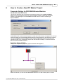
How to Create a New DP Master Project
6
46
How to Create a New DP Master Project
Parameter Setting for PROFIBUS Master Modules
Introduction and Overview
This section describes how to generate the parameter settings for the A(1S)J71PB92D.
Differences to the parameter setting for other PROFIBUS master modules are mentioned
explicitly. After selecting the command New in the File menu choose the module type
A(1S)J71PB92D.
All PROFIBUS DP master modules support an advanced buffer memory management in 244 byte
mode with larger and more flexible data telegrams and thus less delay in the sequence program.
The A(1S)J71PB92D and QJ71PB92D master modules additionally provide a 32 byte mode
(operating mode 0) for compatibility reasons with the MELSEC ProfiMap 1.0 software and with
previous A(1S)J71PB92D modules.
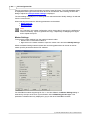
Graphical Network Editor
After you have opened a project the graphical network editor appears:
Within this window you can edit and add additional devices. To add a slave open the context
(c) 2006 MITSUBISHI ELECTRIC CORPORATION
47
GX Configurator-DP
menu by pressing the right mouse button and select 'Insert DP-Slave'. The GSD database dialog
is displayed and the type of the new slave device can be selected. After inserting the slave the
dialog to adjust the slave parameter settings is displayed.
The same dialog is displayed, if an existing slave is selected the item 'Modify Settings' is selected
from the context menu.
When selecting the master the following parameters can be edited:
· Master Settings
· Bus Parameter
Note:
Any changes in the master configuration, which change the I/O structure (i.e add/remove
slaves or modules), require to generate the Copy- respectively I/O Mapping-POU again
and to repeat the import.
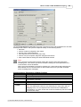
Master Settings
To access the master settings from the graphical network editor:
· Double-click on the master module or
· Right-click on the master module to open the context menu and select Modify Settings
Within the Master Settings network related bus and timing parameters can be set as well as
master specific parameters like the FDL address.
For PROFIBUS modules supporting DP V2, i.e. the QJ71PB92V, the Master Settings dialog is
extended by the input of the clock synchronization interval Watchdog for time sync. This
parameter is disabled and only displayed in grey for the other PROFIBUS modules:
(c) 2006 MITSUBISHI ELECTRIC CORPORATION
How to Create a New DP Master Project
48
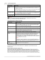
The field ‘Estimated bus cycle time’ shows the expected minimum interval between two I/O data
exchanges with a slave. The cycle time depends mostly on the following factors:
· baud rate
· number of slaves configured in the master
· I/O size of the configured slaves
· max response time of each slave (max Tsdr)
· number of acyclic requests, diagnostic telegrams and retries
· other master stations sharing the same PROFIBUS network
Note:
The cycle time must be observed when setting the minimum slave interval and the
watchdog time. If the actual cycle time exceeds the settings for these parameters, the
communication cannot be started.
When using the estimated cycle time for adjusting min. slave interval and watchdog time
add sufficient time for communication of other masters and for acyclic data exchange
(DPV1 and diagnostic messages).
Communications Parameters of Master Settings
Parameter
Meaning
Name
Shows the project specific name of the master
Baudrate
Transfer rate for the communication. Define a baudrate, which is
supported by all slaves.
FDL address
FDL address (station number)
Starting I/O
number
Module head address on the base unit
Note: the starting I/O number is only necessary for 'Copy POU' and 'I/O
Mapping POU'. It is not required for the download of the PROFIBUS
configuration. For online access the module is identified by the slot number
in the transfer setup.
(c) 2006 MITSUBISHI ELECTRIC CORPORATION
49
GX Configurator-DP
Parameter
Meaning
Error action
flag
Output processing after failure. Select this option, if you want to have the
outputs shut off in case of error (recommended for drives, inverters etc.).
In practice this means:
After occurrence of any network error all outputs of the network are turned
OFF and no diagnostic information from the slaves is returned.
Autom. Refresh
(Q series only)
Sets the automatic refresh parameter of the PROFIBUS master
Consistency
(Q series only)
Ensures data consistency during transfer via AutoRefresh
Note: the AutoRefresh parameter is automatically set, if AutoRefresh has
been selected for data transfer in PLC Settings
Note:
If you change the baud rate, power off the slaves. Otherwise the slaves cannot
synchronize with the newly defined baud rate.
Timing Parameters of Master Settings
Parameter
Description
Min. slave interval
Smallest allowed period of time between two slave poll cycles. This
ensures that the sequence of function requests from the DP master
can be handled by the DP slave. This value is valid for all installed
slaves. The slowest slave defines this value.
Polling timeout
In case of master-master communication this parameter specifies the
max. amount of time it may take the requestor to fetch the response.
Data control time
This parameter defines the period of time during which the master
module notifies the slave of its operation status. This time must be at
least six times the watchdog time of any slave.
Watchdog
This checkbox enables the watchdog checking in all slaves.
Slave Watchdog
time
When the checkbox Watchdog is checked (ON), this specifies the
maximum time without communication, after which the slave will
regard the connection to the master to be broken. If the slave
supports DPV1, the unit will automatically be set to either '10 ms' or '1
ms', depending on the setting of the 'Watchdog Timebase' flag in the
user parameters of the slave.
Note:
The unit can only be changed to '1 ms', if the watchdog option is
enabled for specific slaves. If the watchdog option has been enabled
via the master, all slaves must use the default timebase of '10 ms'.
Watchdog for time
sync.
(QJ71PB92V only)
This parameter specifies the interval, in which time the master
broadcasts the current system time.
If you want to use the factory default values click on <DEFAULT> and all values are set to
standard values.
Autom. Refresh (Q series master only)
The automatic refresh option activates the automatic data exchange between CPU and the
master on the master side. Additionally the autorefresh parameters, i.e. the assignment of CPU
devices to buffer memory addresses, must be written to the CPU. Automatic refresh transfers the
input, output, and (if selected) the diagnostic/communication areas of the PROFIBUS master
to/from a user definable area in the CPU. This ensures a fast and consistent data transfer without
(c) 2006 MITSUBISHI ELECTRIC CORPORATION
How to Create a New DP Master Project
50
using a FROM/TO instruction and extending the cycle time.
Automatic refresh is selected and cleared in the PLC Settings dialog. If either online update of
the CPU or offline update of the GID project have been selected, the automatic refresh option in
the Master Settings dialog is selected as well.
The data areas included in autorefresh and the respective device addresses can be set in PLC
and GX IEC Developer (GID) Settings. The settings in the CPU (stored in the IPARAM file) are
updated together with the download of the configuration to the PROFIBUS module (see
configuration download and online tool) or via a GX IEC Developer (GID) project.
For details refer to the hardware manual of the Q series master module.
The automatic refresh option must be activated to enable the consistency function (see below).
Consistency (Q series master only)
The automatic refresh function (see above) must be activated to enable the consistency function.
Otherwise e.g. output data for a slave may be set in the slave in several segments and not in a
single PROFIBUS cycle.
The consistency function can be activated for System Q CPUs from OS version B (Sep. 2000).
The consistency function interlocks simultaneous access to the buffer memory by the CPU and
the DP master. This way, data consistency especially required for high-speed applications is
automatically ensured.
This interlock mechanism slightly decreases the transfer speed. Therefore, only enable the
consistency function, if you require data consistency.
For details refer to the hardware manual of the Q series master module.
Bus Parameters
To access the bus parameters from the graphical network editor, click on the Bus. Param. button
in the Master Settings dialog.
This function allows to select the baud rate and to modify any parameters like timeouts, which are
related to the baud rate. The settings are stored independently for each baud rate.
Relative timing factors are displayed as absolute times based on the selected baud rate. The
available parameters are:
(c) 2006 MITSUBISHI ELECTRIC CORPORATION
51
GX Configurator-DP
Parameter
Description
Baudrate
Transfer rate (must be supported by all slaves)
T_sl
Slot time (max interval to wait for response)
min T_sdr
min station delay of responder
max T_sdr
max station delay of responder
T_qui
Quiet time
T_set
Setup time
T_tr
Target rotation time
GAP factor
controls the GAP update timer
HSA
highest station address
Max retry limit
max. number of retries
When pressing the <Default> button all values are set to their default values for the currently
selected baud rate.
Note:
If you change the baud rate of an existing PROFIBUS DP network, power off the slaves.
Otherwise the slaves cannot synchronize with the newly defined baud rate.
The inputs are checked against the input limits when leaving the dialog with the <OK> button.
Additionally the following consistency checks are performed:
· min T_sdr < max T_sdr
· T_qui < min T_sdr
· max T_sdr < T_sl
· T_sl < T_tr
Note:
If you are not an experienced PROFIBUS network administrator the bus parameters
should not be changed except in the following cases:
· more than 15 slave stations are connected (target rotation time has to be calculated
again)
· the network consists of more than 1 master (target rotation time has to be calculated
again)
For the correct parameter setting of the target rotation time TTR (t_tr) please refer to the
PROFIBUS standard. However, it is important that the target rotation time is large enough to
enable the master module to poll each connected slave once per token cycle.
Insert DP Slave
In the graphical network editor right-click on the PROFIBUS line to open the context menu. Select
'Insert DP-Slave' to access the GSD Device Database. After having selected a Slave Device
Group, a list of all slave models assigned to the respective group is displayed. For the selected
slave the vendor and revision string, the bitmap and the path of the GSD file and the bitmap file
are displayed.
(c) 2006 MITSUBISHI ELECTRIC CORPORATION
How to Create a New DP Master Project
52
When a model is selected and the <OK> button has been pressed, the Slave Parameter
Settings dialog appears.
Note:
Adding a slave changes the addresses of the I/O data in the buffer memory of the
master. It is therefore necessary to update the PLC program and (if used) the
autorefresh settings.
Duplicate Slave
The configuration of a modular DP slave like the ST1H-PB involves several steps like selecting
the modules and setting the module specific user parameters. If a PROFIBUS network includes
several slaves of the same type, this may require to repeat the same actions for each slave again.
To simplify the procedure it is possible to add an exact copy of an already existing slave to the
project again.
Select a slave and press the right mouse button to display the slave-specific context menu. This
menu contains the entry Duplicate Slave. Click on this menu item to get an additional slave with
the same configuration (selected modules, user parameters etc.) inserted into the PROFIBUS
network. This avoids inserting a new slave of the same type, selecting the modules again and
adjusting the parameter settings.
Note:
The new slave has identical settings compared to the original one. For this reason the
FDL address has to be adjusted and the slave name must be changed after duplicating
the slave.
Note:
Adding a slave changes the addresses of the I/O data in the buffer memory of the
master. It is therefore necessary to update the PLC program and (if used) the
autorefresh settings.
(c) 2006 MITSUBISHI ELECTRIC CORPORATION
53
GX Configurator-DP
Delete Slave
In the graphical network editor select the slave module to be deleted and either:
· press <Del> key or
· Right-click on DP-Slave to open the context menu and select Delete DP-Slave
Note:
Deleting a slave changes the addresses of the I/O data in the buffer memory of the
master. It is therefore necessary to update the PLC program and (if used) the
autorefresh settings.
Modify Settings
The menu item Modify Settings in the context menu of both master and slaves opens the
parameter dialog for the selected device.
Slave Parameter Settings
To access the slave parameter settings from the graphical network editor:
· Double-click on a DP slave or
· Right-click on a DP slave to open the context menu and select Modify Settings
For all PROFIBUS master modules except A(1S)J71PB92D there is an additional Swap I/O Bytes
function.
In the upper part of the window, the name of the selected device and the vendor name are
displayed. If you have selected a wrong device, you can leave this window with the <CANCEL>
button. Then you will return to the Network Configuration. When the correct model is displayed
you have to set the parameters listed in the following table. When pressing the <Default> button
all values are set to their default values.
Parameters in the Slave Parameter Settings have the following meaning:
(c) 2006 MITSUBISHI ELECTRIC CORPORATION
How to Create a New DP Master Project
Item
Description
Name
Name of the slave can be defined. This is for documentation
purpose only.
FDL Address
Station address of the slave
Watchdog
When selected, the watchdog control of the slave is activated.
The slave will check whether the master was in communication
with the slave within the defined watchdog time. If there is no
communication between slave and master within the specified
watchdog time the outputs are turned to the safe state.
Slave Watchdog
time
If you have selected the watchdog function you have to define
the watchdog time interval of the slave. Make sure that the data
control time in the Master Parameter setting is 6 times longer
than the slave watchdog time.
Min T_sdr
Minimum waiting time for a DP slave, until it is allowed to send
response frames to the DP master. Do not change this value.
54
The time is entered as multiple of the bit duration on the
PROFIBUS. The corresponding absolute time depends therefore
on the selected PROFIBUS baud rate.
Group
identification
number
PROFIBUS DP allows to transmit control commands (such as
sync or freeze) from the master to one slave, a group of slaves or
all slaves at the same time. The control commands are based on
multicast function. This means that slaves with the same group
number operate in a synchronized way with each other. A slave
can belong to several groups. You can use the boxes to assign
the slave to any of the groups.
Slave is active
If selected, the slave is included in the cyclic data transfer.
Otherwise the slave is not accessed and a connection failure with
that slave will not cause a response error in the master.
Sync(Output) •
If this option is activated, a synchronous switching of all slave
outputs is possible.
Freeze(Input) •
If this option is activated, a synchronous switching of all slave
inputs is possible.
Ignore AutoClear
The slave should ignore a 'Clear' telegram from the master. This
function is only enabled, if the option 'Goto Clear State' in the
master is set.
Initialize slave
when failing to
respond
Swap I/O Bytes in
Master‚
The master initializes a slave, if communication fails.
DP V1/V2 Slave
Parameters‚
This button is only enabled for slaves, which support the DP
V1/V2 functionality. The GSD file of the slave must contain the
keyword 'DPV1_Slave' with the value '1'. Pressing this button
opens the dialog for DP V1/V2 parameters.
When the Swap I/O Bytes function is activated, the order of each
pair of bytes is reversed by the PROFIBUS master.
• only available for slaves where this function is supported (stated at GSD file)
‚ only available for QJ71PB92V and FX3U-64DP-M projects
Swap I/O Bytes (not for A(1S)J71PB92D)
Several PROFIBUS slave products have a reversed byte order in a word device compared to
Mitsubishi. Activate the Swap I/O Bytes function to have the byte order reversed by the
PROFIBUS master.
(c) 2006 MITSUBISHI ELECTRIC CORPORATION
55
GX Configurator-DP
DP V1/V2 Slave Parameters
To access the DP V1/V2 slave parameters open the Slave Parameter Settings menu and click
on the DP V1/V2 Slave Parameters button.
The parameters have the following meaning:
Item
Description
DP V1 support enabled
Enable supported alarm types.
Watchdog time base 1 ms
The slave interprets the given value for watchdog time
as a multiple of 1 ms instead of 10 ms.
'Fail Safe' function enabled
The slave works in 'Fail Safe' mode.
Slave-specific check of
cfg_data
The slave applies a slave specific check to the
configuration data sent by the master.
Update Alarm
The slave can send Update alarms.
Status Alarm
The slave can send Status alarms.
Manufacturer Specific Alarm
The slave can send Manufacturer Specific alarms.
Diagnostic Alarm
The slave can send Diagnostic alarms.
Process Alarm
The slave can send Process alarms.
Pull/Plug Alarm
The slave can send Pull/Plug alarms.
Allow max. one alarm of
each type
Only one alarm of each type can be sent.
Note:
If the watchdog time has been set for all slaves via the master parameter settings, the
option for setting the WDT time base to 1 ms is disabled.
Extended User Parameters
To access the extended user parameters from the graphical network editor, click on the User
Param. button in the Slave Parameter Settings dialog.
User parameters for the slave device can be defined individually. The purpose of user parameters
is to parameterize the individual slave. For example the slave can be an analog input device and
the operating mode of the input channel must be parameterized at startup of PROFIBUS.
(c) 2006 MITSUBISHI ELECTRIC CORPORATION
How to Create a New DP Master Project
56
In case the slave supports the extended user parameter format click on <User Param.> button to
access the following dialog box.
The Extended User Parameters are not standardized but depend on the slave. The GSD file can
provide descriptive texts for parameters as well as available settings.
If these parameter descriptions are missing or incomplete the user parameters can also be
changed within a simple hex editor. If you prefer to edit unsigned integer values as hex values,
check the <Edit Unsigned as hex> checkbox.
Hex Editor
Click on <Edit Hex> button to access the Hex Editor for the Slave User Parameters. The
relevant area for the selected module is indicated by colored background and arrows. The
address is shown as "tool tip".
(c) 2006 MITSUBISHI ELECTRIC CORPORATION
57
GX Configurator-DP
Be careful when editing these parameters via the hex editor. You should have a detailed slave
documentation from the manufacturer to prevent errors.
Note:
These parameters should only be changed by experienced users. If no extended user
parameter descriptions are available in the slave GSD file, this dialog is opened. Consult
your slave device manufacturer to generate correct settings.
Slave Module Selection
Slave modules represent either modular units, from which the DP slave is assembled, or different
configurations of a compact slave. The modules can be selected after clicking on <Select
Modules> button. This button is enabled depending on the GSD file of the selected PROFIBUS
DP slave.
The following dialog box is displayed:
(c) 2006 MITSUBISHI ELECTRIC CORPORATION
How to Create a New DP Master Project
58
The slave device is the summary of all modules installed in the slave. The GSD file includes all
selectable modules for the slave device. Mark a module in the right list of Installed Modules.
Then select a module in the left list of Available Modules and press the <Add before> or <Add
after> button. If you press the <Add before> button, the module is inserted before the selected
entry in the Installed Modules list or, in case the <Add after> button is pressed, the module is
inserted after the marked module in the Installed Modules list. To remove a module from the
Installed Modules list, select the module and press the <Remove> button. The slot number they
are added to is shown beside the installed modules.
GXDP automatically determines the maximum possible number of modules per slave, the
maximum I/O size and user parameter length. It checks the number of I/O and user parameter
bytes used by the installed modules against these limits.
After clicking <Ok> the Slave Parameter Settings dialog appears again.
Note:
Adding or removing slave modules may change the addresses of the I/O data in the
buffer memory of the master. It is therefore necessary to update the PLC program and (if
used) the autorefresh settings.
Universal Slave Module Type
Some slave GSD files do not contain module descriptions, but require the module configuration
data (‘cfg_data’) to be constructed in the configuration tool via a so-called ‘Universal Module’. If a
slave GSD file does not contain module definitions, GXDP displays the entry Universal in the
Slave Modules dialog. One or more universal module entries can be added to the Installed
Modules list. The maximum input/output size for each module is 16 words or bytes.
Note:
Ensure that the slave can work with the respective settings.
The following sample shows a slave with selected Universal modules.
(c) 2006 MITSUBISHI ELECTRIC CORPORATION
59
GX Configurator-DP
When a Universal module entry in the Installed Module list is double-clicked, the Universal
Module Settings dialog is opened and the properties of the selected universal module, i.e.
consistency, input and output size, can be changed.
If the module should only have an input area, select the option Inputs only and the field for the
output length is hidden.
If the module should only have an output area, select the option Outputs only and the field for the
input length is hidden.
Special Checks for ST Slave
The ST1H-PB slave imposes certain restrictions on the selection of modules. The most important
ones are:
(c) 2006 MITSUBISHI ELECTRIC CORPORATION
How to Create a New DP Master Project
1. The first module must be a head module.
2. Only one head module is possible.
(c) 2006 MITSUBISHI ELECTRIC CORPORATION
60
61
GX Configurator-DP
3. The I/O size of all modules must fit within the buffer of the selected head module.
GXDP checks these restrictions for the ST slave, when the user leaves the Slave Modules dialog
via the <OK> button. If any of these restrictions are violated, an error message is displayed and
the dialog remains open to allow the user to correct the selection.
Project Transfer
When the whole network creation is complete, the project should be saved with the help of the
File menu.
Now you can transfer the whole configuration data stored in the configuration project file (*.dp2) to
the connected PROFIBUS master module. For details refer to online access to the modules
(c) 2006 MITSUBISHI ELECTRIC CORPORATION
Parameter Setting for QJ71PB93D Slave Modules
7
62
Parameter Setting for QJ71PB93D Slave Modules
Introduction
The QJ71PB93D module is a PROFIBUS DP V0 slave for System Q PLCs. It enables a DP
master to access devices in a System Q CPU. The QJ71PB93D is configured partially by the DP
master and by GX Configurator-DP.
The project file for the QJ71PB93D slave module has the extension *.dpx (not *.dp2 as for PB92D
master modules).
Parameter Setting
This chapter describes how to generate the parameter settings for the PROFIBUS slave module
QJ71PB93D.
After selecting the command New in the File menu choose the module type PROFIBUS DP Slave
(QJ71PB93D).
After you have opened a project the following dialog for the slave parameter settings appears:
Here you specify the following parameter settings:
(c) 2006 MITSUBISHI ELECTRIC CORPORATION
63
GX Configurator-DP
Item
Description
FDL_address
This item is used to define the station address of the slave.
Autom. Refresh
Enables Consistency function. See detailed description in
chapter Autom. Refresh
Input Size
Specifies the size of the input area in units of words.
Output Size
Specifies the size of the output area in units of words.
Input CPU Device
Specifies the input device and its start address in the CPU.
The corresponding device range used in the CPU memory is
calculated automatically.
Output CPU Device
Specifies the output device and its start address in the CPU.
The corresponding device range used in the CPU memory is
calculated automatically.
Automatic Refresh
The automatic refresh function sets the automatic refresh parameters for the PROFIBUS slave
QJ71PB93D in the parameter file stored in the System Q CPU. This file manages parameter data
for all special function modules of the System Q.
Via automatic refresh the input and output areas of the PROFIBUS slave are transferred to or
from a user definable device area in the CPU. This method provides direct and fast access
without using FROM/TO instructions.
For details refer to the hardware manual of the QJ71PB93D slave module.
Consistency
The consistency function can be activated for System Q CPUs from OS version B (Sep. 2000).
The consistency function interlocks simultaneous access to the buffer memory by the CPU and
the DP slave. This way, data consistency especially required for high-speed applications is
automatically ensured.
This interlock mechanism slightly decreases the transfer speed. Therefore, only enable the
consistency function, if you require data consistency.
For details refer to the hardware manual of the QJ71PB93D slave module.
Note:
Only the FDL address, the autorefresh flag, and the consistency flag are transferred to
the DP slave. The size settings in the slave parameter settings dialog are relevant only
for the data exchange between DP slave and System Q CPU via autorefresh.
(c) 2006 MITSUBISHI ELECTRIC CORPORATION
I/O Mapping
8
64
I/O Mapping
The purpose of I/O mapping is an easier access to the input and output data cyclically exchanged
between the Profibus master and the connected slaves. In I/O mapping GXDP generates PLC
program code, which will
· transfer output data from buffer devices to the buffer memory of the master
· transfer input data from the buffer memory of the master to the buffer devices
· generate ‘Data Unit Types’ (DUTs) for each slave module
· exchange data with devices selected by the user
· start the cyclic data exchange
· copy contents of diagnostic buffers to assigned devices
· reference I/O data via global variables
Instead of calculating the I/O data offsets of the slave modules within the I/O buffer of the master,
one can read or write the respective global variables for slave modules. These are part of the user
library, which is generated via the menu item POU for GX IEC Developer.
I/O mapping program code is only available for the following master modules and operating
modes
· A(1S)J71PB92D (Mode E only !)
· QJ71PB92D (Mode E only!)
· QJ71PB92V
· FX3U-64DP-M
For the FX3U-64DP-M master module there is also a ‘Copy POU’ available, alternatively to the
'I/O Mapping POU'. It contains the code for exchanging I/O data between the buffer memory of the
master and the slave specific device areas in the CPU and can handle data consistency. The
'Copy POU' does not however include any information on the I/O structure of the slaves.
Note:
There is no I/O mapping and/or Copy POU support for A(1S)J71PB92D and
QJ71PB92D in mode 0.
Dialog for I/O Mapping
To access the dialog for I/O Mapping select a slave in the in the graphical network editor and then
select the item ‘I/O Mapping’ from the context menu.
The dialog is split into two panes
· the left pane with a tree of the master, slaves and slave modules
· the right pane with the I/O areas of the selected slave or module
Tree View
(c) 2006 MITSUBISHI ELECTRIC CORPORATION
65
GX Configurator-DP
The tree view displays the slaves and slave modules in the master configuration project with the
following levels:
Level
Type
Text
1
Master
Type name
2
Slave
FDL address, user assigned name and type name
3
Slave
Module
Type name of module
Table View
When a slave or a slave module is selected in the tree, the table lists the I/O areas of the
respective slave or module. These are represented by elements of DUTs in the generated
program code.
If a slave has been selected:
If a module (here of an ST1H-PB slave) has been selected:
(c) 2006 MITSUBISHI ELECTRIC CORPORATION
I/O Mapping
66
For standard slaves and modules the generated DUT contains one ARRAY OF WORD element
for the input and one for the output area. The array size is determined by the I/O size of the slave
or module, rounding an odd byte size up to the next word boundary. For the modules of ST1H-PB
slaves the generated DUTs contain module specific elements for I/O data, control, status and
error information.
Item
Description
DUT Var. Identifier
Automatically generated name of the global variable instance of the
DUT.
Identifier
Name of the DUT element.
DUT Type
Data type of the DUT element or global variable.
Number Elements
Number of elements. If >1, then the element is an array.
Class
Input (data is transferred from the master to the CPU) or output (data
is transferred from the CPU to the master).
User MIT-Address
Device, to which the I/O point or I/O point array is mapped.
Global Var.
Identifier
Buffer MIT-Address
Separate global variable name for specific I/O point.
The device address of the element within the data exchange buffer.
This buffer has been specified by the user and is used to exchange
the complete inputs and outputs of all slaves with the buffer memory of
the master.
If slave specific transfer has been selected, the device address for
the I/O-area of the slave selected on the left side must be entered
here. If a slave module is however selected on the left side, this
column is write-protected. It shows the calculated device address of
the selected I/O area. On CPU types, where the calculated device
address is actually not accessible, it may still serve as guidance for
locating module I/O points within the transfer device buffer.
Warning:
The buffer MIT-addresses should not be directly accessed. If a 'Copy POU' with the
extended PLC code for slave modules is used, the contents of the DUT variables, which
are generated for all modules, are copied to the buffer devices. Data, which has been
directly written by the application to these devices, is overwritten.
When a module is selected, the user can enter a user device address and/or a global variable
name to an I/O area of the module.
(c) 2006 MITSUBISHI ELECTRIC CORPORATION
67
GX Configurator-DP
User MIT-Address
The purpose of user devices is to access an I/O area via a fixed device address. The buffer
device address of an I/O area should not be referenced by the PLC application program, because
they change, when slaves and/or modules are added or removed.
To assign a user device select the cell in the column ‘User MIT-Address’ and enter the device
address. A list shows the available device types and maximum address ranges. The actually
available device ranges depend on the CPU type and CPU parameters and may be smaller.
Whether a device can actually be used, can only be checked, when the generated code has been
imported into the PLC program.
User devices must not overlap with each other or with the device areas used as I/O transfer
buffer. This restriction is checked, when the I/O mapping editor is closed.
Global Variable Identifier
The PLC code for I/O mapping contains fixed default global variables for the slaves and modules.
The variable name is constructed from the head address of the master, the FDL address of slave
and the slot index of the module. This ensures unique identifiers even if several master modules
are integrated in the same PLC program. The application can access each I/O area by specifying
the name of the DUT variable and the respective DUT element name.
If a fixed application specific name is required, a separate global variable name can be assigned
to an I/O area by entering a unique name in the column ‘Global Var. Identifier’. The generated
code contains a global variable definition of the same type as the DUT element, to which the
variable has been assigned. In that case the corresponding I/O point can be accessed either via
the DUT element or via the global variable.
Two global variables may not have the same name. This restriction is checked, when the I/O
mapping editor is closed.
(c) 2006 MITSUBISHI ELECTRIC CORPORATION
I/O Mapping
(c) 2006 MITSUBISHI ELECTRIC CORPORATION
68
69
9
GX Configurator-DP
Transfer Setup
Introduction
GX Configurator-DP is capable of downloading configuration data to the PROFIBUS master
module via a variety of different communication types. The master module can be located in a
PLC rack directly connected to the PC or in a PLC rack, which is connected to other PLCs in a
separate network.
Note:
The transfer setup is only available in master projects, not in slave projects.
For successful network settings you should be familiar with the characteristics of MELSEC
Ethernet and MELSECNET/10 and consult the corresponding manuals.
Note:
For access to QnA and System Q CPU via MAC select direct connection to CPU port.
The PC-side serial port on the MAC must be set to the same settings as the CPU-side
port, i.e. 8 data bits, 1 stop bit, odd parity and baud rate as set in the respective GX
Configurator-DP transfer path. You can set this parameters with the E-Designer. Select
the item "Comm Settings..." in the "Transfer" menu of the E-Designer. For details refer to
the Operation Manual of the E-Designer.
Combination of AnU and QnA(S) CPUs in a network:
· If GX Configurator-DP is connected to a QnA(S) station in a MELSECNET/10 network,
the QnA(S) CPU must be switched to A mode by hardware switch, if transfer to an AnU is
required.
· If QnA(S) CPUs are existing in a MELSECNET/10 network, a QnA(S) CPU must be the
control station.
· If QnA(S) and AnU CPUs are existing in a MELSECNET/10, a QnA(S) CPU must be the
control station. The AnU CPU can only be accessed from a QnA(S) CPU with hardware
switch in A mode.
Transfer Setup Handling
Opening the transfer setup and defining a network connection
Click on the Transfer Setup button in the toolbar or select Online/Transfer Setup from the main
menu to open the transfer setup. When a new project is created, a default transfer setup is
automatically added to the project file.
When the user presses the <New> button, the user is first asked to select the CPU type.
(c) 2006 MITSUBISHI ELECTRIC CORPORATION
Transfer Setup
70
The CPU types are grouped in families. The available families depend on the type of the master
module according to the table below.
Master Module
Type
Available PLC Families
A(1S)J71PB92D
A- and QnA-series
QJ71PB92D
Q-, QnPH- and QnPRH-series
QJ71PB92V
Q-, QnPH- and QnPRH-series
FX3U-64DP-M
FX-Series
If the user selects a different family, the list of CPU types is updated to match the selected family.
The user can change the CPU type or just press <Ok> button to accept it.
Next the GD transfer setup editor is opened to specify the parameters of the new connection.
Transfer Setup (1)
(c) 2006 MITSUBISHI ELECTRIC CORPORATION
71
GX Configurator-DP
Transfer Setup for QnPRH CPU (2)
(c) 2006 MITSUBISHI ELECTRIC CORPORATION
Transfer Setup
Transfer Setup for FX3U CPU (3)
(c) 2006 MITSUBISHI ELECTRIC CORPORATION
72
73
GX Configurator-DP
Transfer Setup for Q Remote I/O (4)
No
.
Description
PC side I/F
Choose the I/F for the connection of the PC to the PLC.
PLC side I/F
Choose the unit to be connected with the personal computer.
Other station
Choose no network or one of the specified network types
Network route
Choose the network type, network No., station number and first I/O No. to be
accessed. The setting items depend on the network type that has been set.
Coexistence network route
Choose this when making access to the network different from the one where the
personal computer is connected. Choose the network type, network No., station
number and first I/O No. to be accessed. The setting items depend on the network
type that has been set.
Multiple PLC setting
Specify when the access target is multiple CPUs. You can connect up to four PLC
CPUs. In this option you decide which CPU is to be connected.
Connection channel list...
Lists possible connection modes and their image. You can set the connection target
while looking at the Connection channel list.
(c) 2006 MITSUBISHI ELECTRIC CORPORATION
Transfer Setup
74
PLC direct coupled setting
By clicking this button you change from Other station to the own station.
Connection test
Tests whether proper access can be made to the PLC set as the access target on the
Connection Setup screen. If proper access can be made, the model name of the PLC
as the access target appears in the CPU type field
Target System
Specifies the connection destination for redundant PLC systems:
1. Not specified:
· When a PLC is directly connected: the PLC directly connected to the
personal computer
· Via network: The PLC at the station where the network module of the
specified station No. is installed in the network communication path.
2. Control system: The PLC whose system type is the control system.
3. Standby system: The PLC whose system type is the standby system.
4. System A: The PLC connected to the A side connector of the tracking cable.
5. System B: The PLC connected to the B side connector of the tracking cable.
System image
Here you see an image of the setup system.
Line connected(Q/A6TEL,C24).../TEL(FXCPU)...
Clicking on this button opens a dialogue to setup a modem connection.
OK
Closes the dialogue and saves the settings.
Cancel
Closes the dialogue without saving.
Description for Transfer Setup (1 - 4)
Setup of the connection to the PLC
To setup the connection follow the different setup options in Transfer Setup (1). Consult the
manuals of the PLC CPU and the network type you are using.
To select a network type you can also click on the button Connection channel list. The following
dialog window is opened.
(c) 2006 MITSUBISHI ELECTRIC CORPORATION
75
GX Configurator-DP
Dialog Connection channel list
No.
Description
Graphical image of the in
selected network type.
Listing of the possible network configurations for the selected PLC.
Update
Click this button to confirm the selected network configuration without closing the
dialogue
OK
Confirm the set network configuration and close dialogue.
Cancel
Closes the dialogue without saving. When the button Update was clicked the
dialogue is closed but the network configuration is already saved.
Use the scrollbar to scroll through the network configurations and select a network configuration
corresponding to your network type by clicking in the list. Click on the button Update. Confirm the
following security note with OK.
(c) 2006 MITSUBISHI ELECTRIC CORPORATION
Transfer Setup
76
Security note
Test the selected network configuration by clicking on the button Connection test. If the
connection between the PC and the network is possible a positive note will be shown on the
screen. If no connection is possible an error message is shown. In this case you have to check
the cabling as well as the connection parameters set in the transfer setup and, if used, the
respective PLC network modules.
Close the dialog by clicking on OK. The selected network configuration will be saved and shown
in the Transfer Setup.
Dialog Transfer Setup
Now click on System image. An information window is opened in which an image of the setup
system is shown.
In comparison to the Connection channel list dialog in this dialog the system parameter are also
listed.
So you can change single settings and check the settings by the help of this dialog.
(c) 2006 MITSUBISHI ELECTRIC CORPORATION
77
GX Configurator-DP
Dialog System image
After leaving the dialog, the new transfer setup is added with a default name. The default name is
constructed as ‘TransferSetup<n>’, where <n> is the sequential index of the setup. If this name
is already used, <n> is incremented, until the name is unique. Define a network name or just use
the default transfer setup name.
Note:
The network name is used to identify the settings for one transfer path and must therefore
be unique.
The new transfer setup automatically becomes the selected one.
Note:
The length of the network name is limited to 32 characters. The network name can only
contain alphanumeric characters and "_", "-", " ", "(", ")".
Transfer Setup Options
Command New
Creates a new transfer setup. For further information see above Define a New Transfer Setup.
Command Configure
The <Configure> button allows the user to change the settings of the selected transfer setup. The
procedure is the same as for creating a new path. First the user can either confirm the current
CPU type or select a different one. Next the transfer setup is opened, showing the existing
settings.
Command Delete
By pressing the <Delete> button the selected transfer setup is deleted.
(c) 2006 MITSUBISHI ELECTRIC CORPORATION
Transfer Setup
78
Before the setup is actually removed, the user is asked to confirm the operation.
Command Apply
Changes of the transfer setup name and/or the module slot are saved. You can change the
symbolic name of any network connection. Select the network connection you want to change.
Enter the new name in the Transfer Setup Names drop-down list and confirm with the <Apply>
button.
Note:
The length of the transfer setup name is limited to 32 characters. The name can only
contain alphanumeric characters and "_", "-", " ", "(", ")".
If you do not press the <Apply> button after changing the transfer setup name or the slot number
and try to leave the transfer setup or to select a different setup, a message box is displayed that
asks you to confirm the changes.
(c) 2006 MITSUBISHI ELECTRIC CORPORATION
79
GX Configurator-DP
The symbolic name for the transfer setup has changed and can be selected from the Transfer
Setup Names drop-down list.
Command Test
The configured transfer setup can be tested online. When the <Test> button is clicked, a
connection to the master module is initiated in two steps using the configured communication
interfaces and parameters
1. connect to the target PLC
2. connect to the master module within the target PLC with the specified slot
If no module of the type selected in the project is found in the specified slot, a list of the modules
found in the target PLC rack is displayed, so the user can determine the slot number of the master
module and correct it.
If you click on the <Test> button and the connection to the PLC can be established, a message is
displayed.
The type may differ from the CPU type, which the user has set in the selected transfer setup. As
long as the connected CPU belongs to the selected 'PLC Series', the exact CPU type is
automatically detected.
Failing of a PLC CPU connection leads to a warning message.
In that case check the transfer setup settings and the cable connection between PC and PLC.
(c) 2006 MITSUBISHI ELECTRIC CORPORATION
Transfer Setup
If a module of the specified type is found, a confirmation message is displayed.
(c) 2006 MITSUBISHI ELECTRIC CORPORATION
80
81
10
GX Configurator-DP
Web-Based Online Access
The Tools menu includes tools for web-based online access to the network interface modules.
Via the online access configuration projects (*.dp2 for DP masters, *.dpx for DP V0 slaves)
created by GX Configurator-DP can be transferred to the PLC. In addition several diagnostics and
service functions are available.
For this purpose a Server Administrator is supplied which starts a web server on the personal
computer the PLC to be configured is connected to. This web server can be accessed via TCP/IP
by the Tools menu item GX Configurator Client which opens your local standard web browser
together with the correct URL or by an external web browser from a remote or local personal
computer.
Notes:
For connection between Web Server and PLCs you can use a variety of protocols and
network types. For supported networks please see 'Supported connections to PLC'
System requirements for web-based access
(c) 2006 MITSUBISHI ELECTRIC CORPORATION
Web-Based Online Access
82
Supported platforms
Editing master modules and PB93D configuration projects with the GX Configurator-DP software
is supported on Microsoft Windows platforms only.
Server:
Microsoft Windows 98/ Windows Me, Windows NT, Windows 2000, Windows XP
Microsoft Internet Explorer 5.5 or higher
·
·
Client:
Web browser with support of HTML 3 and JAVA2 like Netscape [TM], Microsoft Internet Explorer
[TM], and Conqueror on
· Microsoft Windows 98/ Windows Me, Windows NT, Windows 2000, Windows XP
· LINUX
· Others
Supported DP modules
The firmware of the PROFIBUS master modules must support the configuration via the CPU.
Some older firmware versions of A1SJ71PB92D are accessible only via the serial port on the front
panel of the module. These modules would either require a firmware update or the software
version GX Configurator-DP 4.00.
Module
Min. Firmware
Version
Comments
AJ71PB92D
B
A1SJ71PB92D
F
Older firmware does
not support CPU
access
QJ71PB92D
A
QJ71PB93D
A
QJ71PB92V
A
FX3U-64DP-M
A
Supported PLC types
In general all CPU types which are supported by the respective DP modules are supported by the
configuration software.
Supported are:
·
·
·
·
A series
QnA series
Q series (Q mode only)
FX series
Supported connections to PLC
The following CPU port and network connections from a personal computer (PC) to the PLC are
supported:
· Serial to CPU port in A, QnA, System Q, and FX series PLCs
· USB to CPU port in System Q PLCs
· Ethernet from PC to E71 modules in QnA series and System Q PLCs
· Serial link from PC to QnA PLC and MELSECNET/10 to 2nd level QnA rack
· Ethernet link from PC to QnA PLC and MELSECNET/10 to 2nd level QnA rack
· Serial link from PC to System Q PLC and MELSECNET10 to 2nd level QnA rack
· Ethernet link from PC to System Q PLC and MELSECNET/10 to 2nd level QnA rack
· Serial link from PC to System Q PLC and MELSECNET10 to 2nd level System Q rack
(c) 2006 MITSUBISHI ELECTRIC CORPORATION
83
GX Configurator-DP
· Ethernet link from PC to System Q-PLC and MELSECNET/10 to 2nd level System Q rack
· Serial via MAC to A, QnA series, and System Q PLCs (transparent mode)
Not supported are:
· Ethernet and MELSECNET access to A series PLCs
· Serial access to C24 modules
· CC-link networks
Note:
For successful network settings you should be familiar with the characteristics of
MELSEC Ethernet and MELSECNET/10 and refer to the corresponding manuals.
Server Administrator
The Server Administrator starts a web server on the personal computer the PLC to be
configured is connected to. This web server can be accessed via TCP/IP by the Tools menu item
GX Configurator Client which opens your local standard web browser together with the correct
URL or by an external web browser from a remote or local personal computer.
The Server Administrator can either be started from the Tools menu or from the Start menu as
stand-alone version. It shows the URLs for local and for remote access by an HTML browser.
When started from the Tools menu the Server Administrator provides an additional check box "
This computer is the server". If you clear this check box, a remote server computer name can
be entered. By pressing the Save button this entered name is stored together with the menu item "
GX Configurator Client". The server can only be started or stopped, if it is located on the same
computer. If a server on a remote computer is to be accessed, the server must already be running
on that computer.
When started from the Start menu as stand-alone tool the Server Administrator does not display
an additional check box.
Notes:
The URLs for local or remote web browser access of the server is shown in the fields
URL of the Server Administrator dialog.
The server occupies a TCP port. The number of this port is read from the configuration
files by the Server Administrator and displayed in the field Server TCP Port. This port
number must not be used by any other application running on the same computer.
If you leave the Server Administrator dialog, the server must have been stopped. Otherwise the
following warning message appears:
(c) 2006 MITSUBISHI ELECTRIC CORPORATION
Web-Based Online Access
84
When the server is started, a separate console (DOS) window appears. This window should never
be closed, as this will result in an improper termination of the server. The "Stop Server" function of
the server administrator should be used instead. This will also close the console window, after the
server has been shutdown.
GX Configurator Client
The web server is accessed from the client system via the menu item GX Configurator Client
from the Tools menu or by a stand-alone web browser. The server address (URL) can be taken
from the Server Administrator dialog.
Note:
The web server must have been started via the Server Administrator (see above)
either on your local personal computer or on a personal computer within your TCP/IP
network before it can be accessed by a web browser.
When the GX Configurator Client is started from the menu, the connection to the server is tested.
If the server cannot be accessed, the following warning message appears
Authentication
When you access the web server via a web browser the web page Authentication opens. Here
you have to log in to the web server by entering a valid username and password. Usernames and
passwords are edited and stored in the file users in the GX Configurator-DP directory
server\gxmonitor\Admin.
Valid are for example:
· Username: gxinet
· Password: super
(c) 2006 MITSUBISHI ELECTRIC CORPORATION
85
GX Configurator-DP
The file users is an ASCII file and can be edited with for example Microsoft Notepad. For each
user there is a line in the file with the user name and the password separated by a colon (‘:’).
Optionally the attribute ‘read+write’ can be added, separated from the password with another
colon. This attribute means that the user has read and write access, i.e. he can download a
PROFIBUS configuration or start/stop the CPU. If this attribute is missing, the user can only read
information from the PLC.
Sample contents of users file.
Network Path Selection
After a successful login this web page opens. Here you select a connection to the target PLC to
be configured. Additional network configuration files (*.xml) can also be added to the network
database.
(c) 2006 MITSUBISHI ELECTRIC CORPORATION
Web-Based Online Access
86
Connect
Connect to the selected target PLC to be configured.
Browse
Browse for network configuration files (*.xml) to be uploaded to the web server.
Upload
Upload the browsed network configuration file (*.xml) to the web server to be added to the
network database.
Network Configuration File
Location of Configuration Files
The GXDP webserver loads the configuration of PLC connections from XML files in the
subdirectory ‘Server\gxmonitor\WebApps\config‘. All XML files in this directory are scanned for
valid transfer configurations. As part of the installation procedure the file ‘netwpath_config.xml’ is
copied to this directory. It contains several default configurations for various types of PLC
connections.
The transfer setup editor of GXDP 7.01 does use a different format for storing the transfer
configurations. This new format is not supported by the GXDP webserver included in GXDP 7.01.
To add or modify transfer setups for the webserver the following procedures are possible:
1. edit the existing entries in the default file ‘netwpath_config.xml’
2. add new transfer configurations with new names to the default configuration file ‘
netwpath_config.xml’
3. copy new XML files with additional transfer configurations to the server directory
4. upload new XML files with additional transfer configurations via the start page of the
GXDP webserver
The XML files are text files. If a special XML editor is not available, a simple text editor like ‘
Notepad’ is sufficient.
Elements of a Transfer Path
The configuration for a connection is maintained in ‘NetworkPath’ entries in the configuration files.
Sample for a transfer path:
(c) 2006 MITSUBISHI ELECTRIC CORPORATION
87
GX Configurator-DP
Figure 1The XML network path resembles the actual network architecture
The network path is described by listing the connected components, i. e. the communication
interface on the PC side (XML node <PCNode>) and in the PLC (XML node <PLCModule>). A
network path definition must always contain a node 'PCNode' and one or two nodes of type
'PLCModule'.
Network Path Samples
PC accesses MELSECNET via Serial Port
In this combination a PLC is connected to the PC via a serial link. The user must specify the serial
port on the PC, to which the relaying PLC is connected. On the PLC side the network setup
supports only the serial port in the CPU, not a separate serial board like C24.
The relaying PLC contains a MELSECNET/H board, which is connected to another
MELSECNET/H interface in the target PLC with the PROFIBUS board.
The network and station number of the MelsecNet board in the relaying PLC are not relevant for
the setup of the network path. The MELSECNET boards in both relay and target PLC must share
the same network number and have different station numbers.
(c) 2006 MITSUBISHI ELECTRIC CORPORATION
Web-Based Online Access
88
PC accesses MELSECNET via Ethernet
In this combination a PLC is connected to the PC via ethernet. The PC must therefore know the IP
address of the E71 board in the PLC rack. Connection to the E71 can be tested with the 'ping
<n>.<n>.<n>.<n>' command, where the parameter is the IP address, which has been set in the
network parameters using either GX Developer or GX IEC Developer.
The relaying PLC contains a MELSECNET/H board, which is connected to another
MELSECNET/H interface in the target PLC, which also holds the PROFIBUS board. For this
relaying the PC and the E71 in the PLC must be setup as a virtual MelsecNet, i.e. the E71 must
also be configured with a MelsecNet network and station address. The PC must have a station
address, which must not exist already in the same network number.
The network and station number of the MelsecNet board in the relaying PLC are not relevant for
the setup of the network path. The MelsecNet boards in both relay and target PLC must share the
same network number and have different station numbers.
Rack Configuration
When you are successfully connected to this web page opens. Here the modules found in the
PLC rack are listed including their slot number, head address, and module name.
(c) 2006 MITSUBISHI ELECTRIC CORPORATION
89
GX Configurator-DP
Module Name (underlined)
Opens the web page Module Configuration for a PROFIBUS master (see below) or for a
PROFIBUS slave (see below).
CPU Mode
Displays the current CPU mode. The desired CPU mode can be selected from the drop down list
and set via the <Set> button.
Current Autorefresh Settings
Open the Auto Refresh Settings page. On this page the autorefresh entries in the IPARAM file are
read from the connected PLC CPU, parsed and displayed in a table (see below)
Delete IPARAM File on CPU Module
Deletes the IPARAM file storing the autorefresh settings on the CPU module.
Reload
Reload (refresh) the Rack Configuration dialog.
Module Configuration
This web page shows the current configuration of the DP master module previously selected.
Note:
If the master type set in the project does not match the type of the actually connected
module, the configuration download will fail. If the types of the master modules do not
match, select the correct master type when creating a new project or convert the project
to the correct type.
(c) 2006 MITSUBISHI ELECTRIC CORPORATION
Web-Based Online Access
90
Mode
Displays the current operating mode of the module. The desired operating mode can be selected
from the drop down list and set via the Set button.
Note:
The current FDL address cannot be displayed for the A(1S)J71PB92D.
If you use a A(1S)J71PB92D module the user must set the correct mode with the switch
on the front of the module. The modes are 0 or E for operation mode and 1 for
configuration mode. The module will take over the setting of the mode switch after a CPU
reset.
The mode of a FX3U-64DP-M will not be displayed and also cannot be changed. This
master module supports only one operation mode.
For redundant systems:
Note:
Only the mode of that master module is changed, which is located in the PLC rack
connected to the PC. The second QnPRH system is not accessed via the tracking
cable. If you want to change the mode of both master modules, you must therefore
connect to both modules one after the other.
Depending on the mode of the redundant system, certain restrictions apply:
· Debug mode: the mode of the master modules in both PLC racks can be changed
· Separate mode: device tracking must be turned off, before changes to the
standby master are possible
· Backup mode: the redundant system must first be switched to separate mode
and device tracking must be turned off, before changes to the standby master are
possible
Project
To configure the DP master a configuration project (*.dp2) created by GX Configurator-DP is
required. The Browse button opens a file dialog to browse for such a configuration project on the
(c) 2006 MITSUBISHI ELECTRIC CORPORATION
91
GX Configurator-DP
client computer. The Write to PLC button uploads the selected configuration project to the web
server where it is written to the PLC.
Note:
By downloading a configuration you stop the data exchange on the DP network.
If the configuration download is successful, the following web page appears:
Update Autorefresh in CPU:
Only available for Q series, and only if the CPU is stopped. If selected, the autorefresh settings in
the IPARAM file of the CPU are updated immediately after successfully writing the configuration
project to the PLC.
If an autorefresh entry for this slot is already present in the IPARAM file, it is overwritten with the
settings matching the module configuration. If no IPARAM file is found, it is created. If no entry for
this slot can be found, it is inserted at the appropriate position in the file.
CPU Mode
Displays the current CPU mode. The desired CPU mode can be selected from the drop down list
and set via the <Set> button.
Data Transfer
Manually starts or stops the PROFIBUS DP data transfer for the displayed DP master.
Note:
If you manually start the PROFIBUS DP data transfer, the data transfer will stop after a
reset or after turning on the power supply of the PLC. The PROFIBUS DP data transfer
must be started explicitly by an extra program that sets the startup request signal at the
respective address of the DP master (Y0 + offset: start request signal).
Current Autorefresh Settings
Open the Auto Refresh Settings page. On this page the autorefresh entries in the IPARAM file are
read from the connected PLC CPU, parsed and displayed in a table (see below).
(c) 2006 MITSUBISHI ELECTRIC CORPORATION
Web-Based Online Access
92
Slave List
Opens the web page Slave List (see below)
Current Configuration
Opens the web page Current Module Settings (see below)
Save Configuration
Saves the current module settings in an XML-format file with the default extension *.gxdp. This
function is intended for documentation purposes only. The saved XML-format file does not contain
the full contents of a configuration project file but only the information that is actually on the
module. You can rename the file extension *.gxdp to *.xml and view the file e.g. in a web browser.
Note:
The saved XML-format file cannot be opened in GX Configurator-DP as configuration
project.
Trouble Information
Available only if the external monitoring package is installed. For details refer to the software
manual of the monitoring package. This web page shows monitored error status information.
Auto Refresh Settings
Available only for MELSEC System Q PLCs, except 'Remote I/O'.
(c) 2006 MITSUBISHI ELECTRIC CORPORATION
93
GX Configurator-DP
Note:
At this page the information of all installed modules are displayed.
Slave List
This web page shows status information on the DP slaves connected to the DP master.
Current Module Settings
This web page shows the current configuration of the DP master module previously selected.
(c) 2006 MITSUBISHI ELECTRIC CORPORATION
Web-Based Online Access
94
Module Configuration
This web page shows the current configuration of the PB93D DP slave module previously
selected.
Mode
Displays the current operating mode of the module. The desired operating mode can be selected
from the drop down list and set via the Set button.
· Mode 0: Normal operation mode. Allows upload and download of configuration.
· Mode 2: Diagnostic mode.
Project
To configure the DP slave a configuration project (*.dpx) created by GX Configurator-DP is
required. The Browse button opens a file dialog to browse for such a configuration project on the
client computer. The Write to PLC button uploads the selected configuration project to the web
server where it is written to the PLC.
Update Autorefresh in CPU
Only available, if CPU is stopped. If selected, the autorefresh settings in the IPARAM file of the
(c) 2006 MITSUBISHI ELECTRIC CORPORATION
95
GX Configurator-DP
CPU are updated immediately after successfully writing the configuration project to the PLC.
If an autorefresh entry for this slot is already present in the IPARAM file, it is overwritten with the
settings matching the module configuration. If no IPARAM file is found, it is created. If no entry for
this slot can be found, it is inserted at the appropriate position in the file.
Note:
If the IPARAM file is written into the CPU while GX Developer is running, GX Developer
cannot display the IPARAM file in the list of ”Read from PLC/Delete PLC data”.
Therefore, please update the file list by pressing the ”Refresh View” button of the ”Read
from PLC/Delete PLC data” function.
CPU Mode
Displays the current CPU mode. The desired CPU mode can be selected from the drop down list
and set via the <Set> button.
Data Transfer
Manually starts or stops the PROFIBUS DP data transfer for the displayed DP slave.
Save Configuration
Saves the current module settings in an XML-format file with the extension *.gxdp. In case of a
slave project the current module settings are saved in an XML-format file with the extension *.dpx.
This function is intended for documentation purposes only. The saved XML-format file does not
contain the full contents of a configuration project file but only the information that is actually on
the module. You can rename the file extension .gxdp (.dpx) to *.xml and view the file e.g. in a web
browser.
Note:
The saved XML-format file cannot be opened in GX Configurator-DP as a configuration
project.
(c) 2006 MITSUBISHI ELECTRIC CORPORATION
Troubleshooting
11
96
Troubleshooting
Web Browser Related Hints
Problem 1
Your web browser can not access the GX Configurator-DP web server running on your local
computer or in your local network.
Solution
In case you use a proxy server for the connection of your intranet (LAN) to the Internet ensure that
your web browser bypasses this proxy server for local connections.
In the Microsoft Internet Explorer for example the proxy settings are setup in the dialog
Extras > Internet Options > Connections > LAN Settings:
Other browsers will have similar settings. For further details ask your network administrator.
Problem 2
Your web browser notifies that the addressed server could not be located ("URL not found" etc.).
Solution
The GX Configurator-DP web server needs a little time for initialization. After you have started the
server wait for 15 – 30 seconds before you connect to it.
Problem 3
Inconsistent data especially with several web browsers accessing the server simultaneously
Solution
Accept cookies sent from the GXDP web server. Please check your browser settings.
For example in Internet Explorer 5 open the security settings. Go to the settings for Cookies. The
option "Allow per-session cookies" must either be set to "Enable" or "Prompt". If set to "Prompt",
you will be asked, whether you accept the cookie when connecting to the GXDP web server.
Please press "Yes" to accept the session-cookie.
TCP/IP Network Related Hints
(c) 2006 MITSUBISHI ELECTRIC CORPORATION
97
GX Configurator-DP
Problem 1:
Your web browser cannot connect to the web server computer via the Server Computer Name
displayed in the GX Configurator-DP Server Administrator.
Solution
The Server Computer Name (i.e. DNS Host Name) cannot be resolved by a DNS server.
Microsoft Windows computers have a computer name entered when installing the operating
system, which can also be changed afterwards. This is the "NetBIOS name". Usually this name is
the only name of this computer across a network.
But it is also possible to assign a second name to the computer for the "Domain Name Service
(DNS)". This is the "DNS Host Name"
In the example below a Microsoft Windows NT 4 computer has the original (NetBIOS) name
"Derry" shown in its Network properties dialog under the Identification tab:
(c) 2006 MITSUBISHI ELECTRIC CORPORATION
Troubleshooting
98
In the TCP/IP Properties dialog under the DNS tab we enter the new DNS Host Name "hugo" in
the Host Name field. This name is not registered on a DNS server.
(c) 2006 MITSUBISHI ELECTRIC CORPORATION
99
GX Configurator-DP
When the DNS Host Name (here: "hugo") and the NetBIOS name (here: "derry") differ, GX
Configurator-DP displays the following message box:
When you use the DNS Host Name on another (client) computer as communication target the
other computer will try to get the IP address from a DNS server. If the target computer is not found
by its DNS Host Name, it is not possible to communicate with it.
Using the NetBIOS name or the IP address as communication target should succeed because
computers in a Microsoft Windows network send their names as broadcasts to other computers.
Microsoft Windows 9x provides similar settings. With Microsoft Windows 2000 and Windows XP
the network configuration has changed a lot. It is not as easy anymore to assign a separate DNS
computer name.
For further details ask your network administrator.
(c) 2006 MITSUBISHI ELECTRIC CORPORATION
Index
M
Table of Contents
F
File menu
Change Master Type 24
Close 20
Configuration Image 23
Exit 26
Export 21
New 18
Open 19
Page Setup 25
POU for GX IEC Developer
Print 24
Recent Files 26
Save 20
Save as 20
100
Menus
Toolbar Items
16
O
Online menu
Download Config.Image 42
Download to Module... 37
Start/Stop PROFIBUS 42
Transfer 37
Transfer Setup 36
Upload Config.Image 42
Verify 40
21
P
Parameter Setting for QJ71PB93D Slave Modules
Automatic Refresh 63
Consistency 63
H
S
Help menu
About... 45
Index 45
Using Help 45
How to Create a New DP-Project
Autom. Refresh (Q series master only)
Bus Parameters 50
Delete Slave 53
DP V1/V2 Parameters 55
Duplicate Slave 52
Extended User Parameters 55
Graphical Network Editor 46
Insert DP Slave 51
Master Settings 47
Modify Settings 53
Swap I/O Bytes 54
I
I/O Mapping
Dialog for I/O Mapping 64
Table View 65
Tree View 64
User MIT-Address 67
(c) 2006 MITSUBISHI ELECTRIC CORPORATION
49
Setup menu 27
Adding devices 29
CPU Device Access 32
GSD Device Database 28
GSD Update 30
GX IEC Developer (GID) Settings 35
MXChange support 27
Options 35
PLC and GX IEC Developer (GID) Settings
Slave device group 31
Updating DPV1 Slave Settings 30
T
Tools menu 43
AutoRefresh Settings 92
GX Configurator Client 84
Server Administrator 83
Starting GX Conffigurator-ST
System requirements 81
Transfer Setup
Transfer Setup Handling 69
Transfer Setup Options 77
43
32
101
GX Configurator-DP
Troubleshooting
Web browser related hints
96
V
View menu
Status bar 44
Toolbar 44
Zoom In 44
Zoom Out 44
W
Window menu
1,2,3,... 44
Arrange Icons
Cascade 44
44
(c) 2006 MITSUBISHI ELECTRIC CORPORATION
MITSUBISHI ELECTRIC