1
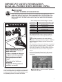
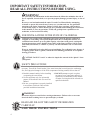
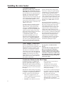
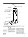
Use & Care Manual With Installation Instructions for the Installer Electric Residential Heat Pump Water Heaters Residential 50 Gallon - HB Series The purpose of this manual is twofold: one, to provide the installer with the basic directions and recommendations for the proper installation and adjustment of the water heater; and two, for the owner– operator, to explain the features, operation, safety precautions, maintenance and troubleshooting of the water heater. This manual also includes a parts list. It is imperative that all persons who are expected to install, operate or adjust this water heater read the instructions carefully so they may understand how to perform these operations. If you do not understand these instructions or any terms within it, seek professional advice. Any questions regarding the operation, maintenance, service or warranty of this water heater should be directed to the seller from whom it was purchased. If additional information is required, refer to the section on “If you need service.” DO NOT destroy this manual. Please read carefully and keep in a safe place for future reference. Recognize this symbol as an indication of Important Safety Information! ! ! Printed in USA © 2013 Rheem Manufacturing Co. alifornia Proposition 65 C Warning: This product contains chemicals known to the State of California to cause cancer, birth defects or other reproductive harm. 92-103234-12 AP16244-1 (06/13) Safety Information Safety Precautions. . . . . . . . 3-4 FOR YOUR RECORDS Write the model and serial numbers here: # Installation Instructions Location. . . . . . . . . . . . . . . . . . 5 Water Connections . . . . . . . . . 6 Condensate Drain . . . . . . . . . . 6 # You can find them on a label on the appliance. Staple sales slip or cancelled check here. Proof of the original purchase date is needed to obtain service under the warranty. Relief Valve. . . . . . . . . . . . . . . 7 Electrical Connections. . . . 8-9 Pipe Insulation. . . . . . . . . . . 10 Installation Checklist. . . . . . . 11 READ THIS MANUAL Operating Instructions Inside you will find many helpful hints on how to use and maintain your water heater properly. Just a little preventive care on your part can save you a great deal of time and money over the life of your water heater. Safety Controls . . . . . . . . . . 12 Water Temperature . . . . . . . . 12 Basic Water Heater Operation . . . . . . . . . . . . . . . . . . . . . . .13-14 You’ll find many answers to common problems in the Before You Call For Service section. If you review our chart of Troubleshooting Tips first, you may not need to call for service at all. READ THE SAFETY INFORMATION Care and Cleaning Draining. . . . . . . . . . . . . . . . 15 Maintenance. . . . . . . . . . . . . 15 Your safety and the safety of others are very important. There are many important safety messages in this manual and on your appliance. Always read and obey all safety messages. ! Extended Shut-Down. . . . . 16 Troubleshooting Tips Before You Call For Service. . . . . . . . . . . . . . 17 This is the safety alert symbol. Recognize this symbol as an indication of Important Safety Information! This symbol alerts you to potential hazards that can kill or hurt you and others. All safety messages will follow the safety alert symbol and either the word “DANGER”, “WARNING”, “CAUTION” or “NOTICE”. These words mean: An imminently hazardous situation ! DANGER that will result in death or serious injury. Customer Service Parts List. . . . . . . . . . . . . . . . 20 Wiring Diagram. . . . . . . . . . 22 If You Need Service. . . . . . . . . . . . . . . . . 24 2 ! A potentially hazardous situation that WARNING ! CAUTION could result in death or serious injury and/or damage to property. A potentially hazardous situation that may result in minor or moderate injury. Attention is called to observe a NOTICE: specified procedure or maintain a specific condition. IMPORTANT SAFETY INFORMATION. READ ALL INSTRUCTIONS BEFORE USING. DANGER! WATER TEMPERATURE SETTING Safety and energy conservation are factors to be considered when selecting the water temperature setting of water heater. Water temperatures above 125°F can cause severe burns or death from scalding. Be sure to read and follow the warnings outlined on the label pictured below. This label is also located on the water heater near the thermistor access panel. Time/Temperature Relationship in Scalds ! DANGER Temperature Time To Produce a Serious Burn 120°F (49°C) 125°F (52°C) 130°F (54°C) 135°F (57°C) 140°F (60°C) 145°F (63°C) 150°F (65°C) 155°F (68°C) More than 5 minutes 1½ to 2 minutes About 30 seconds About 10 seconds Less than 5 seconds Less than 3 seconds About 1½ seconds About 1 second Table courtesy of Shriners Burn Institute The chart shown above may be used as a guide in HOT determining the proper water temperature for your home. DANGER: Households with small children, disabled, or elderly persons may require a 120°F or lower thermostat setting to prevent contact with “HOT” water. ! BURN Water temperature over 125°F can cause severe burns instantly or death from scalds. Children, disabled and elderly are at highest risk of being scalded. See instruction manual before setting temperature at water heater. Feel water before bathing or showering. Temperature limiting valves are available, see manual. NOTICE: Mixing valves are available for reducing point of use water temperature by mixing hot and cold water in branch water lines. Contact a licensed plumber or the local plumbing authority for further information. The temperature of the water in the heater is regulated by the water heater interface control. To comply with safety regulations the temperature was set at 120°F before the water heater was shipped from the factory. The illustration below shows the water temperature setting. Refer to the Operating Instructions in this manual for detailed instructions in how to adjust the water temperature. ! DANGER: Hotter water increases the potential for Hot Water SCALDS. 3 IMPORTANT SAFETY INFORMATION. READ ALL INSTRUCTIONS BEFORE USING. WARNING! For your safety, the information in this manual must be followed to minimize the risk of fire or explosion, electric shock, or to prevent property damage, personal injury, or loss of life. Be sure to read and understand the entire Use and Care Manual before attempting to install or operate this water heater. It may save you time and cost. Pay particular attention to the Safety Instructions. Failure to follow these warnings could result in serious bodily injury or death. Should you have problems understanding the instructions in this manual, or have any questions, STOP, and get help from a qualified service technician, or the local electric utility. FOR INSTALLATIONS IN THE STATE OF CALIFORNIA California Law requires that residential water heaters must be braced, anchored or strapped to resist falling or horizontal displacement due to earthquake motions. For residential water heaters up to 52-gallon capacity, a brochure with generic earthquake bracing instructions can be obtained from: Office of the State Architect, 1102 Q Street, Suite 5100, Sacramento, CA 95814 or you may call 916-445-8100 or ask a water heater dealer. However, applicable local codes shall govern installation. For residential water heaters of a capacity greater than 52 gallons, consult the local building jurisdiction for acceptable bracing procedures. CAUTION: DO NOT “crush” or otherwise impair the removal of the “plastic” front (side) panel. SAFETY PRECAUTIONS Have the installer show you the location of the circuit breaker and how to shut it off if necessary. Turn off the circuit breaker if the water heater has been subjected to overheating, fire, flood, physical damage or if the ECO (temperature limiting control) fails to shut off. ● Read this manual entirely before installing or operating the water heater. ● Use this appliance only for its intended purpose as described in this Use and Care Manual. ● DO NOT attempt to repair or replace any part of your water heater unless it is specifically recommended in this manual. All other servicing should be referred to a qualified technician. ● Be sure your appliance is properly installed in accordance with local codes and the provided installation instructions. WARNING! Disconnect all power to unit before starting maintenance. Failure to do so can cause electrical shock resulting in severe personal injury or death. READ AND FOLLOW THIS SAFETY INFORMATION CAREFULLY. SAVE THESE INSTRUCTIONS 4 Installing the water heater The location chosen for the water heater must take into consideration the following: Local Installation Regulations This water heater must be installed in accordance with these instructions, local codes, utility codes, utility company requirements or, in the absence of local codes, the latest edition of the National Electrical Code. It is available from some local libraries or can be purchased from the National Fire Protection Association, Batterymarch Park, Quincy, MA 02269 as booklet ANSI/NFPA 70. Locate the water heater in a clean dry area as near as practical to the area of greatest heated water demand. Long un-insulated hot water lines can waste energy and water. such areas cannot be avoided, it is recommended that a suitable catch pan, adequately drained, be installed under the water heater. Canadian installations should refer to CSA22.1, a copy can be purchased from the Canadian Standards Association, 5050 Spectrum Way, Mississauga,ONT L4W 5N6 Location Place the water heater in such a manner that the thermistor and element access panels can be removed to permit inspection and servicing such as removal of elements or checking controls. The water heater and water lines should be protected from freezing temperatures. Do not install the water heater in outdoor, unprotected areas. Make certain the floor underneath the water heater is strong enough to sufficiently support the weight of the water heater once it is filled with water. NOTICE: Auxiliary catch pan MUST conform to local codes. Catch Pan Kits are available from the store where the water heater was purchased, or any water heater distributor. Catch Pan should not obstruct cold inlet or drain valve. ! CAUTION: The water heater should not be located in an area where leakage of the tank or connections will result in damage to the area adjacent to it or to lower floors of the structure. Where NOTICE: Installation in a closet or confined space is not allowed. It is recommended that the Heat Pump Water Heater be installed in a location providing approximately 1,000 cu. ft of unconditioned air. Installation in an enclosed room smaller than 1000 cubic feet (10'x10'x10') is permissible provide that adequate inlet/outlet ventilation is provided, such as louvered door, to allow heat to enter the room. If louvered door is used, it is recommended that it provide a minimum of two 8"x14" register openings, one at the top and the other at the bottom of the door, and that these be kept fully opened. Clearances Rear 2" Top 8" Min. B A—Diameter of water heater plus 2" min.. B—Maximum 2″ A To open drain, line should be at least 3/4″ ID and pitched for proper drainage. Inspect Shipment Inspect the water heater for possible damage. Check the markings on the rating plate of the water heater to be certain the power supply corresponds to the water heater requirements. Rating plate is located on front of water heater. Refrigerant This heat pump water heater is factory charged with an environmentally friendly, non-chlorinated refrigerant, R410A. This refrigerant has zero ozone depletion potential. 5 Installing the water heater Thermal Expansion Determine if a check valve exists in the inlet water line. Check with your local water utility. It may have been installed in the cold water line as a separate back flow preventer, or it may be part of a pressure reducing valve, water meter or water softener. A check valve located in the cold water inlet line can cause what is referred to as a “closed water system”. A cold water inlet line with no check valve or back flow prevention device is referred to as an “open” water system. As water is heated, it expands in volume and creates an increase in the pressure within the water system. This action is referred to as “thermal expansion”. In an “open” water system, expanding water which exceeds the capacity of the water heater flows back into the city main where the pressure is easily dissipated. A “closed water system”, however, prevents the expanding water from flowing back into the main supply line, and the result of “thermal expansion” can create a rapid and dangerous pressure increase in the water heater and system piping. This rapid pressure increase can quickly reach the safety setting of the relief valve, causing it to operate during each heating cycle. Thermal expansion, and the resulting rapid and repeated expansion and contraction of components in the water heater and piping system can cause premature failure of the relief valve, and possibly the heater itself. Replacing the relief valve WILL NOT correct the problem! The suggested method of controlling thermal expansion is to install an expansion tank in the cold water line between the water heater and the check valve (refer to the illustration on the next page). The expansion tank is designed with an air cushion built in that compresses as the system pressure increases, thereby relieving the over pressure condition and eliminating the repeated operation of the relief valve. Other methods of controlling thermal expansion are also available. Contact your installing contractor, water supplier or plumbing inspector for additional information regarding this subject. Water Supply Connections Refer to the illustration on the next page for suggested typical installation. The installation of unions or flexible copper connectors is recommended on the hot and cold water connections so that the water heater may be easily disconnected for servicing if necessary. The HOT and COLD water connections are clearly marked and are 3/4″ NPT on all models. Install a shut-off valve in the cold water line near the water heater. See page 8 on "To Fill The Water Heater". NOTICE: DO NOT apply heat to the HOT or COLD water connections. If sweat connections are used, sweat tubing to adapter before fitting adapter to the water connections on heater. Any heat applied to the water supply fittings will permanently damage the dip tube and/or heat traps. Condensate Drains for the Heat Pump Consult local codes or ordinances for specific requirements. Refer to page 7. 6 than connection size provided on condensate drain. IMPORTANT: When making drain fitting connections to the drain tubing, use a thin layer of piping tape or silicone and install hand tight. • All drain lines must be pitched downward away from the unit a minimum of 1/8" per foot of line to ensure proper drainage. IMPORTANT: When making drain fitting connections to the drain tubing, DO NOT overtighten. Overtightening fittings can split pipe connections on the drain pan. • Do not connect condensate drain line to a closed or open sewer pipe. DO NOT allow condensate to drain into the water heater drain pan. • This unit is equipped with a 3/4" primary condensate connection and a 1/2" overflow connection. • • DO NOT reduce drain line size less The drain line should be insulated where necessary to prevent sweating and damage due to condensate forming on the outside surface of the line. Typical Installation Ceiling 8" Minimum clearance above heat pump to allow air circulation Heat pump filter Primary condensation (3/4") to open drain or outdoors Secondary condensate tubing (1/2") to open drain or outdoors Electrical access cover Union Hot water outlet to fixtures Temperature and pressure relief valve and discharge line Shut off valve Cold water supply Thermal expansion tank (if required) Heat trap 6" Min Union 6" Air gap Drain valve A new combination temperature and pressure relief valve, complying with the Standard for Relief Valves and Automatic Gas Shut-Off Devices for Hot Water Supply Systems, ANSI Z21.22/CSA 4.4, is installed in the opening provided. No valve of any type should be installed between the relief valve and the tank. Local codes shall govern the installation of relief valves. Relief Valve ! WARNING: The pressure rating of the relief valve must not exceed 150 PSI, the maximum working pressure of the water heater as marked on the rating plate. The BTUH rating of the relief valve must not be less than the input rating of the water heater as indicated on the rating label located on the front of the heater (1 watt=3.412 BTUH). Connect the outlet of the relief valve to a suitable open drain so that the discharge water cannot contact live electrical parts or persons and to eliminate potential water damage. Piping used should be of a type approved for hot water distribution. The discharge line must be no smaller than the outlet of the valve and must pitch downward from the valve to allow complete drainage (by gravity) of the relief valve and discharge line. The end of the discharge line should not be threaded or concealed and should be protected from freezing. No valve of any type, restriction or reducer coupling should be installed in the discharge line. 7 Installing the water heater ! WARNING: The tank must be full of water before heater is turned on. The water heater warranty does not cover damage or failure resulting from operation with an empty or partially empty tank. To Fill the Water Heater Make certain the drain valve is completely closed. allow the air to vent from the water heater and piping. Open the shut-off valve in the cold water supply line. A steady flow of water from the hot water faucet(s) indicates a full water heater. Open each hot water faucet slowly to EcoNet™ Communication Port EcoNet™ communication port is for future integration with home automation, energy management, and demand response systems EcoNet™ Port Ground Screw Electrical Power Hookup Terminals SCALE 0.400 Electrical Connections ! WARNING! Turn off electric power at the fuse box or service panel before making any electrical connections. Also, the ground connection must be completed before making line voltage connections. Failure to do so can result in electrical shock, severe personal injury or death. 8 Disconnect all power to unit before starting maintenance. Failure to do so can cause electrical shock resulting in severe personal injury or death The unit must be grounded. Failure to do so can cause electrical shock resulting in severe personal injury or death. Electrical Connections continued... A separate branch circuit with copper conductors, over current protective device and suitable disconnecting means must be provided by a qualified electrician. All wiring must conform to local codes or latest edition of National Electrical Code ANSI/NFPA 70. ! CAUTION: The presence of water in the piping and water heater does not provide sufficient conduction for a ground. Non-metallic piping, dielectric unions, flexible connectors etc. can cause the water heater to be electrically isolated. The water heater is completely wired to the Electrical Power Hookup Terminals inside the jacket at the top front of the water heater. An opening for 1/2″ or 3/4″ electrical fitting is provided for field wiring connections. The voltage requirements and wattage load for the water heater are specified on the rating plate on the front of the water heater. The branch circuit wiring should include either: Metallic conduit or metallic sheathed cable approved for use as a grounding conductor and installed with fittings approved for the purpose. Non-metallic sheathed cable, metallic conduit or metallic sheathed cable not approved for use as a ground conductor shall include a separate conductor for grounding. It should be attached to the ground terminals of the water heater and the electrical distribution box. • 208-230V 1PH • 24.0 Max. AMP draw • 10 gauge wire • Recommended 30 AMP overcurrent protection. Insulation Blankets ! WARNING: If local codes require external application of insulation blanket kits the manufacturer’s instructions included with the kit must be carefully followed. Insulation blankets, available to the general public, for external use on electric water heaters are not necessary. The purpose of an insulation blanket is to reduce the standby heat loss encountered with storage tank heaters. This water heater meets or exceeds the National Appliance Energy Conservation Act standards with respect to insulation and standby loss requirements making an insulation blanket unnecessary. ! CAUTION: If local codes require the application of an external insulation blanket to this water heater, pay careful attention to the following so as not to restrict the proper function and operation of the water heater: The manufacturer’s warranty does not cover any damage or defect caused by installation, attachment or use of any type of energy saving or other unapproved devices (other than those authorized by the manufacturer) into, onto or in conjunction with the water heater. The use of unauthorized energy saving devices may shorten the life of the water heater and may endanger life and property. Do not apply insulation to the top of the heat pump. The manufacturer disclaims any responsibility for such loss or injury resulting from the use of such unauthorized devices. Do not cover the operating or warning labels attached to the water heater or attempt to relocate them on the exterior of insulation blanket. Do not cover the coils around the sides of the heat pump. Do not cover the Temperature Control, temperature and pressure relief valve or drain valve. Inspect the insulation blanket frequently. Filter Coils 9 Installing the water heater Relief and DrainValve Insulation Installation For increased energy efficiency, this water heater has been supplied with two 2-3/8” sections of pipe insulation. ! CAUTION: Ensure the T&P Valve opening is not obstructed by the insulation. Please install the insulation, according to the illustration at left. Slip the insulation cover over the T&P Valve through the center hole and align the hole in the side with the opening of the T&P Valve. Slip the insulation cover over the drain valve through the center hole. Hot and Cold Pipe Insulation Installation Hot Water Outlet Relief Valve Cold Water inlet Drain Valve 10 Please install the insulation on the cold water supply inlet and the hot water outlet as shown in the illustration. Installation Checklist A. Water Heater Location ❑ Close to area of heated water demand. ❑ Provisions made to protect area from water damage. ❑ Indoors and protected from moisture, wet conditions and freezing temperatures. ❑ Sufficient room to service heater. ❑ Area free of flammable vapors. ❑ 1,000 cu. ft unconditioned indoor space. ❑ Eight inches (8") of clearance from ceiling to top of heat pump water heater to allow for air circulation. ❑ Access to condensate disposal. B. Water Supply ❑ Water heater completely filled with water. ❑ Water connections tight and free of leaks. ❑ Air purged from water heater and piping. C. Relief Valve ❑ Temperature and Pressure Relief Valve properly installed and discharge line run to open drain. ❑ Discharge line protected from freezing. D. Wiring ❑ Power Supply voltage agrees with water heater rating plate. ❑ Branch circuit wire and fusing or circuit breaker of proper size. (Recommended 30 amp breaker) ❑ Electrical connections tight and unit properly grounded. ❑ 10 gauge wire. E. Condensate Lines ❑ Condensate lines from heat pump installed correctly. ❑ Condensate lines from heat pump run to a suitable drain location. 11 Operating the water heater CAUTION: Hydrogen gas can be produced in a hot water system served by this water heater that has not been used for a long period of time (generally two weeks or more). HYDROGEN GAS IS EXTREMELY FLAMMABLE!! To dissipate such gas and to reduce risk of injury, it is recommended that the hot water faucet be opened for several minutes at the kitchen sink before using any electrical appliance connected to the hot water system. If hydrogen is present, there will be an unusual sound such as air escaping through the pipe as the water begins to flow. DO NOT smoke or use an open flame near the faucet at the time it is open. Safety Precautions o turn off power to water heater D if it has been subjected to over heating, fire, flood, physical damage. o Not turn on water heater D unless it is filled with water. o Not turn on water heater if D cold water supply shut-off valve is closed. there is any difficulty in If understanding or following the Operating Instructions or the Care and Cleaning section, it is recommended that a qualified person or serviceman perform the work. Safety Controls WARNING: If the water heater has been subjected to flood, fire, or physical damage, turn off power and water to the water heater. Do not operate the water heater again until it has been thoroughly checked by qualified service personnel. The water heater is equipped with a temperature limiting control (ECO) that is located above the upper heating element in contact with the tank surface. If for any reason the water temperature becomes excessively high, the temperature limiting control (ECO) breaks the power circuit to the heating element. Once the control opens, it must be reset manually. CAUTION: The cause of the high temperature condition must be investigated by qualified service technician and corrective action must be taken before placing the water heater in service again. To reset the temperature limiting control: (Refer to Illustration on page 21): Turn off the power to the water heater. Remove the top jacket access panel and insulation. Press the red RESET button. Replace the insulation, jacket access panel and plastic housing before turning on the power to the water heater. Water Temperature Setting ! DANGER: There is a hot water scald potential if the thermostat is set too high. Households with small children, disabled, or elderly persons may require a 120°F or lower thermostat setting to prevent contact with HOT water. The temperature of the water in the water heater can be regulated by selecting the desired temperature on control display. the warnings outlined in this manual and on the label on the water heater. This label is located on the front of the water heater. Safety and energy conservation are factors to be considered when selecting the water temperature setting of the water heater. The lower the temperature setting, the greater the savings in energy and operating costs. Mixing valves for reducing point of use water temperature by mixing hot and cold water in branch water lines are available. Contact a licensed plumber or the local plumbing authority for further information. To comply with safety regulations the temperature is factory set at 120°F or less where local codes require. This is the recommended starting point. The chart on the page 3 may be used as a guide in determining the proper water temperature for your home. Water temperatures above 125°F can cause severe burns or death from scalding. Be sure to read and follow 12 Basic Water Heater Operation Navigating the Home Screen Temperature Setting Current Operating Condition Temperature Adjustment Operational Control Button Operating Mode Button Settings Button Service Button Operational Control Once power is supplied to the water heater, the Operational Control Buttons can be used to activate the heating of water. To turn the water heating "On", select the "Standby" button on the Home Screen to "Enable" the system. Water Heater ships in the default "Energy Saver" mode with a temperature setting of 120° F. Recommended temperature setting 120° F. For DOE test, temperature is set to 135° F. To turn the water heating "OFF", select the "Enabled" button on the Home Screen to "Standby" the system. Temperature Adjustment DANGER: Hotter water Tank temperature will be maintained according to the setting on the Home Screen. If the water temperature setting needs adjustment, use the arrows on the increases the potential for control display to select desired temperature. HOT water SCALDS 13 Basic Water Heater Operation Operating Mode Press the "Mode" button to utilize the five major modes of operation: The active mode is displayed on the top of the screen Heat Pump Only This mode will heat with compressor operation only and will not use any electric heat during typical heating and demand cycles. This mode will minimize power consumption. Energy Saver - Factory set mode for shipping. This mode optimizes compressor and electric heat that results in water heater performance that meets Energy Star requirements. As a result, compressor operation will be maximized and use of electric heat will be minimized. High Demand This mode will maximize the performance of the water heater while still providing good energy savings.Water heater operates with simultaneous compressor and electric heat. Electric Only This Mode will heat with the electric resistance elements. This mode should only be used during compressor maintenance periods. This mode will result in maximum power consumption. Vacation This mode will allow duration setting between 2 and 28 days or set indefinitely with the "Hold" setting. Tank temperature will be maintained at about 82º F. Only compressor operation will be allowed as needed. Settings The Settings Screen allows the following changes: The Display Units: The temperature display on the Home Screen can be set to Fahrenheit or Celsius Home Screen Lock: The Home Screen can be locked to eliminate accidental changing of the Mode or Temperature Beep on Alarm: The audible Alarm tone can be disabled during service periods Service The Service screen provides information on the current status, product description, diagnostics, testing, temperature readings, and alarms. Alarm details can be found in the “Troubleshooting Alarm Codes” section of the manual. 14 Care and cleaning of the water heater Draining the Water Heater CAUTION: Shut off power to the water heater before draining water. DANGER: Before manually operating the relief valve, make certain no one will be exposed to the hot water released by the valve. The water drained from the tank may be hot enough to present a scald hazard and should be directed to a suitable drain to prevent injury or damage. In order to drain the water heater, turn off the cold water supply. Open a hot water faucet or lift the handle on the relief valve to admit air to the tank. Attach a garden hose to the drain valve on the water heater and direct the stream of water to a drain. Open the valve. Routine Preventative Maintenance WARNING: Disconnect all power to unit before starting maintenance. Failure to do so can cause electrical shock resulting in severe personal injury or death. DANGER: Before manually operating the relief valve, make certain no one will be exposed to the danger of coming in contact with the hot water released by the valve. The water may be hot enough to create a scald hazard. The water should be released into a suitable drain to prevent injury or property damage. NOTICE: If the temperature and pressure relief valve on the hot water heater discharges periodically, this may be due to thermal expansion in a closed water system. Contact the water supplier or your plumbing contractor on how to correct this. Do not plug the relief valve outlet. Properly maintained, your water heater will provide years of dependable trouble-free service. It is suggested that a routine preventive maintenance program be established and followed by the user. It is further recommended that a periodic inspection of the electronic control, heat pump and wiring should be made by service personnel qualified in electric appliance repair. Most electrical appliances, even when new, make some sound when in operation. If the hissing or singing sound level increases excessively, Contact a qualified installer or plumbing contractor to inspect. IMPORTANT: See "DANGER on left". At least once a year, lift and release the lever handle on the temperature pressure relief valve, located on the side of the water heater, to make certain the valve operates freely. Allow several gallons to flush through the discharge line to an open drain. A water heater’s tank can act as a setting basin for solids suspended in the water. It is therefore not uncommon for hard water deposits to accumulate in the bottom of the tank. It is suggested that a few quarts of water be drained from the water heater’s tank every month to clean the tank of these deposits. Rapid closing of faucets or solenoid valves in automatic water using appliances can cause a banging noise heard in a water pipe. Strategically located risers in the water pipe system or water hammer arresting devices can be used to minimize the problem. Filter Handle Filter It is recommended to clean the filter on top of the heat pump every month. Clean by washing with mild detergent and water. Dry and replace over discharge fan. Remove the filter by lifting up on the handle at front of the heat pump and lifting it off the air discharge fan. See Figure on right. 15 Care and Cleaning of the Water Heater Vacation and Extended Shut-Down NOTICE: Refer to the Hydrogen Gas Caution in the Operating Instructions. If the water heater is to remain idle for an extended period of time, the power and water to the appliance should be turned off to conserve energy and prevent a build-up of dangerous hydrogen gas. After a long shut-down period, the water heater’s operation and controls should be checked by qualified service personnel. Make certain the water heater is completely filled again before placing it in operation. The water heater and piping should be drained if they might be subjected to freezing temperatures. Anode Rod NOTICE: Do not remove the anode rod from the water heater’s tank. Operation with the anode rod removed will greatly shorten the life of the glass lined tank and will exclude warranty coverage. 16 This water heater is equipped with an anode rod designed to prolong the life of the glass-lined tank. The anode rod is slowly consumed, thereby eliminating or minimizing corrosion of the glass-lined tank. Water sometimes contains a high sulfate and/or mineral content and together with cathodic protection process can produce a hydrogen sulfide, or rotten egg odor in the heated water. Chlorination of the water supply should minimize the problem. Before You Call For Service… Troubleshooting Tips Save time and money! Review the chart on this page first and you may not need to call for service. Problem Possible Causes Rumbling noise Water conditions in your ● Allow a few quarts of water to run from drain valve home caused a build up of to remove sediment settlings. scale or mineral deposits in the water heater. Relief valve producing popping noise or draining Pressure build up caused by thermal expansion in a closed system ● T his is an unacceptable condition and must be corrected. Contact the water supplier or plumbing contractor on how to correct this. Do not plug the relief valve outlet Not enough or no hot water Water usage may have exceeded the capacity of the water heater. A fuse is blown or a circuit breaker tripped Electric supply may be off ● W ait for the water heater to recover after an abnormal demand The thermostat may be set too low. ● See the Temperature regulation of the water heater section of this manual Leaking or open hot water faucets Electric service to your home may be interrupted Improper wiring. ● Make sure all faucets are closed Manual reset limit (ECO) ● S ee the Temperature regulation of the water heater Refer to page 3 for more information. Cold water inlet temperature may be colder during the winter months Not enough clearance above heat pump to allow air to circulate. The thermostat is set too high. ● T his is normal. The colder inlet water takes longer to heat. Water is too hot What to Do ● Replace fuse or reset circuit breaker ● Make sure electric supply to water heater and section of this manual. ● Contact the local electric utility. ● See the Installing the water heater section of this manual. ● M ake sure there is at least 8" of air space between the top of the heat pump and the ceiling. ● S ee the Temperature regulation of the water heater section of this manual ! CAUTION: For your safety DO NOT attempt repair of electrical wiring, thermostats, heating elements or other safety devices. Refer repairs to qualified service personnel. 17 Troubleshooting Alarm Codes Troubleshooting Tips Save time and money! Review the chart on this page first and you may not need to call for service. The water heater will make an audible beep for notification of Alarms. The following steps should be used in determining the Alarm code: 1) Press Blinking "Service" Button on the Home Screen ! 2) Press Blinking "Alarm" Button on the Service Screen Current Alarm 3) Alarm will be listed on Alarm Screen The following page details Alarm code 18 History of all Alarms. (up to 25 Alarms) Troubleshooting Alarm Codes The Following Alarms will not Allow any Heating of Water. Code Possible Causes A008 Heater is not full of water A101 Improperly installed or malfunctioning Thermistor Improperly installed or malfunctioning Thermistor Improperly installed or malfunctioning Thermistor Improperly installed or malfunctioning Thermistor Malfunctioning Compressor What to Do Refer "To Fill the Water Heater" section of this manual A200 High Temperature ECO has tripped Refer to "Safety Control" section of this manual Improper Input Voltage supplied Refer to "Electrical Connections" section of this manual A103 Improperly installed or malfunctioning Refer to "Replacement Parts" and/or Thermistor "Service" sections of this manual A104 Improperly installed or malfunctioning Refer to "Replacement Parts" and/or Thermistor "Service" sections of this manual D001 Communication error between display and Refer to "Replacement Parts" and/or control board "Service" sections of this manual The Following Alarms will not Allow Heating using the Heat Pump System. Possible Causes What to Do Code A102 A105 A106 A004 Refrigerant Levels Incorrect T005/A005 Malfunctioning Compressor Air Filter Clogged T006/A006 Evaporator Fan Malfunction Refrigerant Levels Incorrect Malfunctioning Compressor T007/A007 A500 Refrigerant Levels Incorrect Electronics Malfunction Refer to "Replacement Parts" and/or "Service" sections of this manual Refer to "Replacement Parts" and/or "Service" sections of this manual Refer to "Replacement Parts" and/or "Service" sections of this manual Refer to "Replacement Parts" and/or "Service" sections of this manual Refer to "Replacement Parts" and/or "Service" sections of this manual Refer to "Replacement Parts" and/or "Service" sections of this manual Refer to "Replacement Parts" and/or "Service" sections of this manual Refer to "Routine Preventative Maintenance" section of this manual Refer to "Replacement Parts" and/or "Service" sections of this manual Refer to "Replacement Parts" and/or "Service" sections of this manual Refer to "Replacement Parts" and/or "Service" sections of this manual Refer to "Replacement Parts" and/or "Service" sections of this manual Refer to "Replacement Parts" and/or "Service" sections of this manual 19 Replacement Parts. Instructions For Placing a Parts Order Address parts orders to the distributor or store where the heater was purchased. All parts orders should include: The model and serial number of the water heater from the rating plate located on the tank jacket. Part description (as noted below) and number of parts desired. ! CAUTION: For your safety DO NOT attempt repair of electrical wiring, heating elements, heat pump or electronic controls. Refer repairs to qualified service personnel. pecify voltage and wattage as S marked on the rating plate. Air Filter Control Board Display Assembly (Removed for Clarification of Replacement Parts) Temperature & Pressure Relief valve Upper Thermistor & ECO Element Lower Thermistor Drain Valve 20 Element Cavity Covers Cavity Insert Instructions The following instructions are intended for qualified service personnel ONLY, and should only be done when necessary. In order to replace the ECO,thermistor or heating element, remove the cavity insert crossbar by following the instructions below: Turn off the power to the water heater. Remove the jacket access panel(s) and insulation. Rotate the crossbar up and down until it breaks away from the remainder of the cavity insert. (See illustration to the left) Discard the crossbar. It cannot and need not be replaced. Replace the ECO,thermistor and/or element as necessary. Replace the insulation, jacket access panel(s) and plastic housing before turning on the power to the water heater. NOTICE: The cavity insert crossbar is necessary for the manufacturing process only. The removal of the crossbar will not interfere with the operation of the water heater. 21 Wiring Diagram 22 Wiring Schematic 23 IF YOU NEED SERVICE 1. Should you have any questions about your new water heater, or if it requires adjustment, repair, or routine maintenance, it is suggested that you first contact your installer, plumbing contractor or previously agreed upon service agency. In the event the firm has moved, or is unavailable, refer to the telephone directory, commercial listings or local utility for qualified service assistance. 2. Should your problem not be solved to your complete satisfaction, you should then contact the Manufacturer’s National Service Department at the following address: 1241 Carwood Court Montgomery, Alabama 36117 Phone: 1-800-995-0982. When contacting the manufacturer, the following information will be requested: a. Model and serial number of the water heater as shown on the rating label located on front of the water heater. b. Address where the water heater is located and physical location. c. Name and address of installer and any service agency who performed service on the water heater. d. Date of original installation and dates any service work was performed. e. Details of the problems as you can best describe them. f. List of people, with dates, who have been contacted regarding your problem. 24