1
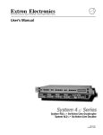
System 8/10 Plus
System Switcher
68-078-01
Printed in USA
Safety Guide
Safety Instructions • English
This symbol is intended to alert the user of important operating and maintenance
(servicing) instructions in the literature provided with the equipment.
This symbol is intended to alert the user of the presence of uninsulated "dangerous
voltage" within the product's enclosure that may present a risk of electric shock.
Caution: To prevent the risk of shock, do not remove the cover (or open
the enclosure). There are no user-serviceable parts inside. Refer
servicing to qualified service personnel.
Caution
Read Instructions • Read and understand all safety and operating instructions before using the
equipment.
Retain Instructions • The Safety Instructions should be kept for future reference.
Follow Warnings • Follow all warnings and instruction marked on the equipment or in the user
information.
Avoid Attachments • Do not use (tools or) attachments that are not recommended by the
equipment manufacturer because they may be hazardous.
Warning
Power Sources • This equipment should be operated only from the power source indicated on the
product. This equipment is intended to be used with a main power system with a grounded
(neutral) conductor. The third (grounding) pin is a safety feature, do not attempt to bypass or
disable it.
Power Disconnection • To remove power from the equipment safely, remove all power cords from
the rear of the equipment, or the desktop power module (if detachable), or from the power source
receptacle (wall plug).
Power Cord Protection • Power cords should be routed so that they are not likely to be stepped on
or pinched by items placed upon or against them.
Servicing • Refer all servicing to qualified service personnel. Do not attempt to service this
equipment yourself because opening or removing covers may expose you to dangerous voltage
or other hazards.
Slots and Openings • If the equipment has slots or holes in the enclosure, these are provided to
prevent overheating of sensitive components inside. These openings must never be blocked by
other objects.
Lithium Battery • Danger of explosion if battery is incorrectly replaced. Replace only with the same
or equivalent type recommended by the manufacturer. Dispose of used batteries according to the
manufacturer's instructions.
Consignes de Sécurité • FRANÇAIS
Ce symbole sert à avertir l’utilisateur que la documentation fournie avec le matériel
contient des instructions importantes concernant l’exploitation et la maintenance
(réparation).
Ce symbole sert à avertir l’utilisateur de la présence dans le boîtier de l’appareil de
« tensions dangereuses » non isolées posant des risques d’électrocution.
Attention : Afin d’éviter tout danger d’électrocution, ne pas enlever le
couvercle (ni ouvrir le boîtier). Aucun des éléments internes ne peut être
réparé par l’utilisateur. S’adresser à un technicien de maintenance
qualifié.
Attention
Lire les instructions• Prendre connaissance de toutes les consignes de sécurité et d’exploitation
avant d’utiliser le matériel.
Conserver les instructions• Ranger les consignes de sécurité afin de pouvoir les consulter à
l’avenir.
Respecter les avertissements • Observer tous les avertissements et consignes marqués sur le
matériel ou présentés dans la documentation utilisateur.
Eviter les pièces de fixation • Ne pas utiliser de pièces de fixation (ni d’outils) non recommandés
par le fabricant du matériel car cela risquerait de poser certains dangers.
Avertissement
Alimentations• Ne faire fonctionner ce matériel qu’avec la source d’alimentation indiquée sur
l’appareil. Ce matériel doit être utilisé avec une alimentation principale comportant un fil de terre
(neutre). Le troisième contact (de mise à la terre) constitue un dispositif de sécurité : n’essayez
pas de la contourner ni de la désactiver.
Déconnexion de l’alimentation• Pour mettre le matériel hors tension sans danger, déconnectez
tous les cordons d’alimentation de l’arrière de l’appareil ou du module d’alimentation de bureau
(s’il est amovible) ou encore de la prise secteur.
Protection du cordon d’alimentation • Acheminer les cordons d’alimentation de manière à ce que
personne ne risque de marcher dessus et à ce qu’ils ne soient pas écrasés ou pincés par des
objets.
Réparation-maintenance • Faire exécuter toutes les interventions de réparation-maintenance par
un technicien qualifié. L’utilisateur ne doit pas essayer de procéder lui-même à ces opérations
car l’ouverture ou le retrait des couvercles risquent de l’exposer à de hautes tensions et autres
dangers.
Fentes et orifices • Si le boîtier de l’appareil comporte des fentes ou des orifices, ceux-ci servent à
empêcher les composants internes sensibles de surchauffer. Ces ouvertures ne doivent jamais
être bloquées par des objets.
Lithium Batterie • Il a danger d'explosion s'll y a remplacment incorrect de la batterie. Remplacer
uniquement avec une batterie du meme type ou d'un ype equivalent recommande par le
constructeur. Mettre au reut les batteries usagees conformement aux instructions du fabricant.
Sicherheitsanleitungen • Deutsch
Dieses Symbol soll den Benutzer auf wichtige Anleitungen zur Bedienung und Wartung
(Instandhaltung) in der Dokumentation hinweisen, die im Lieferumfang dieses Gerätes
enthalten ist.
Dieses Symbol soll den Benutzer darauf aufmerksam machen, daß im Inneren des
Gehäuses dieses Produktes gefährliche Spannungen, die nicht isoliert sind und die
einen elektrischen Schock verursachen können, herrschen.
Achtung: Zur Vermeidung eines elektrischen Schocks bitte nicht die
Abdeckung entfernen (oder das Gehäuse öffnen). Im Inneren des
Gerätes sind keine Teile enthalten, die vom Benutzer gewartet werden
können. Eine Wartung sollte nur durch einen qualifizierten technischen
Service durchgeführt werden.
Achtung
Lesen der Anleitungen • Bevor Sie das Gerät zum ersten Mal verwenden, sollten Sie alle
Sicherheits-und Bedienungsanleitungen genau durchlesen und verstehen.
Aufbewahren der Anleitungen • Die Sicherheitsanleitungen sollten aufbewahrt werden, damit Sie
später darauf zurückgreifen können.
Befolgen der Warnhinweise • Befolgen Sie alle Warnhinweise und Anleitungen auf dem Gerät oder
in der Benutzerdokumentation.
Keine Zusatzgeräte • Verwenden Sie keine (Werkzeuge oder) Zusatzgeräte, die nicht ausdrücklich
vom Hersteller empfohlen wurden, da diese eine Gefahrenquelle darstellen können.
Vorsicht
Stromquellen • Dieses Gerät sollte nur über die auf dem Produkt angegebene Stromquelle
betrieben werden. Dieses Gerät wurde für eine Verwendung mit einer Hauptstromleitung mit
einem geerdeten (neutralen) Leiter konzipiert. Der dritte Stift oder Kontakt ist für einen
Erdschluß, und stellt eine Sicherheitsfunktion dar und sollte nicht umgangen oder außer Betrieb
gesetzt werden.
Stromunterbrechung • Um das Gerät auf sichere Weise vom Netz zu trennen, sollten Sie alle
Netzkabeln aus der Rückseite des Gerätes oder aus dem Desktop-Strommodul (falls dies
möglich ist) oder aus der Wandsteckdose ziehen.
Schutz des Netzkabels • Netzkabel sollten stets so verlegt werden, daß sie nicht im Weg liegen
und niemand darauf treten kann oder Objekte darauf- oder unmittelbar dagegengestellt werden
können.
Wartung • Alle Wartungsmaßnahmen sollten nur von qualifiziertem Servicepersonal durchgeführt
werden. Versuchen Sie in keinem Fall, dieses Gerät selbst zu warten, da beim Öffnen oder
Entfernen der Abdeckungen die Gefahr eines elektrischen Schlags oder andere Gefahren
bestehen.
Schlitze und Öffnungen • Wenn das Gerät Schlitze oder Löcher im Gehäuse aufweist, dienen diese
zur Vermeidung einer Überhitzung der empfindlichen Teile im Inneren. Diese Öffnungen dürfen
niemals von anderen Objekten blockiert werden.
Litium-Batterie • Explosionsgefahr, falls die Batterie nicht richtig ersetzt wird. Ersetzen Sie nur
durch diegleiche oder einen vergleichbaren Batterietyp, der auch vom Hersteller empfohlen wird.
Entsorgung der verbrauchten Batterien bitte gemäß den Herstelleranweisungen.
Instrucciones de seguridad • Español
Este símbolo se utiliza para advertir al usuario sobre instrucciones importantes de
operación y mantenimiento (o cambio de partes) que se desean destacar en el
contenido de la documentación suministrada con los equipos.
Este símbolo se utiliza para advertir al usuario sobre la presencia de elementos con
"voltaje peligroso" sin protección aislante, que puedan encontrarse dentro de la caja o
alojamiento del producto, y que puedan representar riesgo de electrocución.
Precaución: Para evitar riesgo de electrocución, no extraer la tapa (ni
abrir la caja). En el interior no hay partes a las que el usuario deba
acceder. Solicitar el servicio de personal técnico calificado.
Precaucion
Leer las instrucciones • leer y analizar todas las instrucciones de operación y seguridad, antes de
usar el equipo.
Conservar las instrucciones • conservar las Instrucciones de Seguridad para futura consulta.
Obedecer las advertencias • todas las advertencias e instrucciones marcadas en el equipo o en la
documentación del usuario, deben ser obedecidas.
Evitar el uso de accesorios • no usar herramientas o accesorios que no sean especificamente
recomendados por el fabricante, ya que podrian implicar riesgos.
Advertencia
Alimentación eléctrica • este equipo debe conectarse únicamente a la fuente/tipo de alimentación
eléctrica indicada en el mismo. La alimentación eléctrica de este equipo debe provenir de un
sistema de distribución general con conductor neutro a tierra. La tercera pata (puesta a tierra) es
una medida de seguridad, no puentearia ni eliminaria.
Desconexión de alimentación eléctrica • para desconectar con seguridad la acometida de
alimentación eléctrica al equipo, desenchufar todos los cables de alimentación en el panel
trasero del equipo, o desenchufar el módulo de alimentación (si fuera independiente), o
desenchufar el cable del receptáculo de la pared.
Protección del cables de alimentación • los cables de alimentación eléctrica se deben instalar en
lugares donde no sean pisados ni apretados por objetos que se puedan apoyar sobre ellos.
Reparaciones/mantenimiento • solicitar siempre los servicios técnicos de personal calificado. No
intentar personalmente la reparación/mantenimiento de esteequipo, ya que al abrir o extraer las
tapas puede quedar expuesto a voltajes peligrosos u otros riesgos.
Ranuras y aberturas • si el equipo posee ranuras u orificios en su caja/alojamiento, es para evitar
el sobrecalentamiento de componentes internos sensibles. Esta aberturas nunca se deben
obstruir con otros objetos.
Batería de litio • existe riesgo de explosión si esta batería se coloca en la posición incorrecta.
Cambiar esta batería únicamente con el mismo tipo (o su equivalente) recomendado por el
fabricante. Desachar las baterías usadas siguiendo las instrucciones del fabricante.
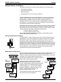
System 8/10 Plus Switcher Series
Getting Started..........
tt
Step 1 uu
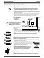
If the System 8/10 Plus is already configured for your model of projector, go to Step 4. If it is
not set up correctly, it will be necessary to change switch settings on the System 8/10 Plus
Main Controller Board. Continue with Step 2 below to verify the correct configuration.
tt
Step 2 uu
Use a small screwdriver to remove the access cover from the front panel of the System 8/10
Plus. Please refer to the illustration on page 3-3 of your User’s Manual.
___ Before changing anything, remove the AC power cord to the System 8/10 Plus and also turn the
projector’s power off.
tt
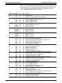
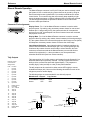
Step 3 uu
Using the configuration information which came with your Communications Kit or is on the
switcher’s label, set the System 8/10 Plus switches. The following table and diagram are to
be used only as an example of a typical configuration. Continue with Step 4 below when your
configuration is correct.
Config
as
✔
Model
Rotary Switches
RS1 RS2 RS3 RS4
Your Model
0
0
F
Cable
J2/J3
B
ON
J2
1
2
3
4
5
6
1 2
3
↓
↑
7
↓
8
9
SW15 Settings
4 5 6 7 8
↓
↑
↓
↓
↓
9 10
Comm
Adapter
↑
26-467-01
↓
10
SW15 DIP Switch
RS2
RS3
RS5 RS2 RS1
RS4
RS1
RS3 RS4
Configured For:
RS-232
tt
Step 4 uu
Locate the Address DIP switches on the rear panel, lower right, of the switcher. Unless this is
part of a master/slave system, set #3 and #5 to the up position and the others to the down
position.
tt
Step 5 uu
Please refer to the connection diagram and instructions for your projector (see your System
8/10 Plus Projector Communications Kit instructions). Using the appropriate Communications
Adapter included in your Communications Kit, connect the Comm extension cable from the
Projector Control port of the System 8/10 Plus to the Comm Adapter. Secure the Comm
Adapter to the correct projector port. Connect all other required signal cables according to
the connection diagram.
Extron • System 8/10 PLUS • User’s Manual
Contents
Extron • System 8/10 PLUS • User’s Manual
Contents
CONTENTS
Chapter One - Introduction to System 8/10 PLUS
Introduction .................................................................................................................... 1-1
Equipment Description ...................................................................................... 1-1
Standard Features ............................................................................................ 1-2
Universal Projector Control ............................................................................... 1-2
Description of Features ..................................................................................... 1-3
Specifications .................................................................................................... 1-4
Packing List ...................................................................................................... 1-5
Chapter Two - Rear Panel Connections
Rear Panel Overview ..................................................................................................... 2-1
Rear Panel Controls and Indicators .................................................................. 2-1
DIP Switch Types .............................................................................................. 2-1
Input Section ..................................................................................................... 2-2
Output Section .................................................................................................. 2-2
Video Loop Back (VLB) ..................................................................................... 2-2
Power ............................................................................................................... 2-2
Applications ................................................................................................................... 2-3
Input Configurations ....................................................................................................... 2-4
Input Switches and Output LEDs ...................................................................... 2-4
Video Output Connections ............................................................................................. 2-5
Audio Connections ......................................................................................................... 2-6
RGB (Analog) Input Connections ................................................................................... 2-7
Input Selection Switches ................................................................................... 2-7
Composite Video (NTSC/PAL) Input Connections ......................................................... 2-8
Input Selection Switches ................................................................................... 2-8
S-Video Input Connections ............................................................................................ 2-9
Input Selection Switches ................................................................................... 2-9
Video Loop Back (VLB) ................................................................................................ 2-10
Normal Mode .................................................................................................. 2-10
VLB Mode ....................................................................................................... 2-10
VLB Restrictions ............................................................................................. 2-10
VLB Operation ................................................................................................ 2-11
Special Features .......................................................................................................... 2-12
Input Selection Switches ................................................................................. 2-12
Cabling a System 8/10 PLUS in a Rack ......................................................................... 2-13
Chapter Three - Projector/Monitor Installation
Projector/Monitor Installation .......................................................................................... 3-1
Projector Control Port ....................................................................................... 3-2
User-Supplied Communications Cables ............................................................ 3-2
Stand Alone Operation ...................................................................................... 3-3
Address Switch Settings ................................................................................... 3-3
Configuration Setup .......................................................................................... 3-3
Removing the Access Cover ............................................................................. 3-3
Extron Comm Adapters ..................................................................................... 3-4
Setting the System 8/10 PLUS for the Projector .............................................................. 3-4
Triple-Action Switching™ (RGB Delay Switch - RS5) ....................................... 3-4
Extron • System 8/10 PLUS • User’s Manual
i
Contents
Chapter Four - Controlling the Switcher
Controlling the System 8/10 PLUS Switchers .................................................................. 4-1
Manual Remote Control .................................................................................... 4-1
RS-232 Control ................................................................................................. 4-1
Front Panel Buttons and Indicators ................................................................................ 4-2
Button Labels .................................................................................................... 4-3
Front Panel Access Cover ................................................................................ 4-3
Chapter Five - Multiple Switcher Operation
Multiple Switcher Installation .......................................................................................... 5-1
Saving Configurations to Memory ..................................................................... 5-1
Master/Slave Configurations ............................................................................. 5-1
DIP Switch Types .............................................................................................. 5-2
Looping Two Switchers .................................................................................................. 5-2
Daisy Chain Connection ................................................................................................ 5-3
Looping Instructions .......................................................................................... 5-3
Daisy Chain Example ........................................................................................ 5-4
Star Connection ............................................................................................................. 5-5
Looping Instructions .......................................................................................... 5-5
Star Configuration Example .............................................................................. 5-6
System 4 with One System 8/10 PLUS Switcher ............................................................. 5-7
System 4 with Multiple System 8/10 PLUS Switchers ...................................................... 5-8
System 8/10 PLUS Switch Settings ................................................................................. 5-9
Appendix A - RS-232 Programming Guide
Programming the System 8/10 PLUS .............................................................................. A-1
RS-232 Connections ......................................................................................... A-1
RS-232 Protocol ............................................................................................... A-1
Program Instructions ......................................................................................... A-1
Simple Instruction Set ....................................................................................... A-1
Related Terms ................................................................................................................ A-2
Selecting Inputs Using Delimiters .................................................................................. A-2
Command/Response Table ............................................................................................ A-3
Appendix B - Reference
Manual Remote Operation ............................................................................................. B-1
Connector Pin Assignments .............................................................................. B-1
Tally Outputs ..................................................................................................... B-1
Related Parts List .......................................................................................................... B-2
Removing the System 8/10 PLUS Cover ......................................................................... B-3
Changing SW1 Switch Settings ..................................................................................... B-3
Changing the Host Baud Rate ....................................................................................... B-4
Installing the Infrared Remote IC Chip ........................................................................... B-5
Infrared Remote Control Operation ................................................................................ B-6
Changing the Projector Control Software Chip ............................................................... B-7
Changing the Switcher Control Software Chip ............................................................... B-8
Enlever le couvercle du Système 8/10 PLUS (French) .................................................... B-9
Câbler un Système 8/10 PLUS sur un rack (French) ..................................................... B-10
Entfernung der System 8/10 PLUS Abdeckung (German) ............................................. B-11
Verkabelung vom System 8/10 PLUS innerhalb eines Gestells (German) ..................... B-12
Glossary of Terms ........................................................................................................ B-14
ii
Extron • System 8/10 PLUS • User’s Manual
Contents
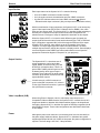
Legend of Icons
______ Important information – for example, an action or a step that must be done
before proceeding.
______ A Warning – possible dangerous voltage present.
_______ A Warning – possible damage could occur.
_____ A Note, a Hint, or a Tip that may be helpful.
_______ Possible Electrostatic Discharge (ESD) damage could result from touching
electronic components.
______ Indicates word definitions. Additional information may be referenced in another
section, or in another document.
Extron’s System 8/10 Plus Switcher Manual
68-078-01, Rev. F, 99-02
New format without projectors
Printed in the USA
Extron • System 8/10 PLUS • User’s Manual
iii
Notes
iv
Extron • System 8/10 PLUS • User’s Manual
Introduction to System 8/10 PLUS
System
System 8/10
8/10 P
PLUS
LUS Switcher
Switcher
User’s
User’s Manual
Manual
1
1
Chapter One
Chapter One
Introduction
to System
8/10
PLUS
Introduction
to System
8/10
PLUS
Equipment Description
Equipment
Description
Configurations
Configurations
Features
Features
Specifications
Specifications
Extron • System 8/10 PLUS • User’s Manual
Introduction to System 8/10 PLUS
General
Introduction
Although each EXTRON System 8/10 PLUS switcher has been factory preset for the
requested projector brand configuration, it can easily be changed to make your
system switcher compatible with any projector brand you choose.
This manual has been carefully written in an effort to provide you with the
detailed information that you need to connect your System 8/10 PLUS switcher to
most projectors available in today’s market. It covers both the System 8 PLUS
and the System 10 PLUS, however, since the only difference between these two
switchers is the number of inputs, they will be referred to as “System 8/10 PLUS”.
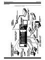
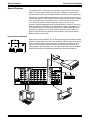
KP-10 Keypad
Remote Control
Hi Carol
Hi Carol
RS-232 Control Device
System 8 PLUS
Infrared System
Remote
Intercommunication
Port for Multiple
System 8/10 Plus
Switchers
Stereo
Amplifier
Computer
Interface
High Resolution
CAD/CAM Workstation
Either of 2 Audio
Outputs
Large Screen Projector
Computer
Interface
MAC II Computer
Laserdisc Player
NTSC or PAL Video
Cassette Player
Communication
Cable
Projector-Specific
Communications Adapter
Computer
Interface
SVGA Compatible
Computer
Equipment Description
The Extron System 8/10 PLUS switchers are microprocessor controlled with BNC
type input and output connectors for video. The built-in microprocessor provides
for digital control of all major graphics projectors. Video formats supported are:
• Composite Video (NTSC/PAL)
• S-Video/S-VHS (YC)
• RGBS (RGB w/separate composite sync)
• RGsB (RGB w/sync on green)
• RGBHV (RGB w/separate H & V sync)
The switchers also feature stereo audio follow with an attenuation level control
for any of the previously mentioned video input formats. Audio inputs can be
attached through the Phoenix® brand captive screw terminal connectors or
through BNC connectors when using Composite Video and S-Video only.
1-1
Extron • System 8/10 PLUS • User’s Manual
Introduction to System 8/10 PLUS
Features
The system switcher can be controlled by the front panel switches, through its
manual remote connector (using EXTRON or third-party remote control devices), or
from a Host through an RS-232 connector. To address large installations with
more than 10 inputs, the switchers can be looped for a total of up to 154 inputs
(17 switchers). Features like Video Loop Back (VLB) make this switcher
adaptable to most application requirements.
Standard Features
•
•
•
•
•
•
•
•
•
•
•
•
•
•
•
•
•
•
Audio-follow switching
Audio Breakaway (RS-232 only)
Balanced audio inputs and outputs
Audio Mute button
Bandwidth of 300 MHz
Eight (System 8) or ten (System 10) inputs (expandable when looped)
Video inputs terminated at 75 Ω (when not selected)
Dual microprocessor control
Projector power button
Projector video mute
Switcher RGB mute
Triple-Action Switching™ (RGB delay)
Contact closure and Tally remote control
RS-232 remote control
Video Loop Back
UL approved and CE compliant
Universal inputs
Universal projector control
Universal Projector Control
The System Switchers are compatible with many major brands of digital control
projectors on the market including:
•
•
•
•
•
•
•
•
•
Ampro
Barco
Digital Projection
Eiki
Epson
Electrohome
Hughes/JVC
InFocus
Mitsubishi
•
•
•
•
•
•
•
•
NEC/Runco
Panasonic
Sanyo
Seleco
Sharp
Sony
Toshiba
Zenith
If your projector manufacturer is not included in the above list, please contact
your Extron representattive.
The System 8/10 PLUS switchers are factory preset for the projector brand of
your choice, but can quickly and easily be reconfigured in the field for any other
compatible brand. Projector control from the switcher includes video muting and
turning projector power on/off. For some projectors, the projector’s remote
control device can be used to control the System 8/10 PLUS switcher as well.
Universal Inputs
All video and audio formats are supported with five BNC and 6-pin Phoenix®
connectors per input channel.
Extron • System 8/10 PLUS • User’s Manual
1-2
Introduction to System 8/10 PLUS
Features
Description of Features
Outputs — Because switching is direct, the output will always have the same
format as the selected input. Separate output connectors are provided for RGBS,
Composite Video, S-Video, and Audio.
Video Loop Back (VLB) — This feature allows the switcher to integrate with either
RGB decoders or scan doublers. With VLB, a Composite or S-Video output is
routed from the switcher output through a decoder or scan doubler and then
back into System 8/10 PLUS switcher. This means that one decoder or scan
doubler can be used for all the video inputs instead of needing one unit for each
video source.
Triple-Action Switching™ (RGB delay) — This prevents image scrambling during
switching time. When an input is selected, Triple-Action Switching® will:
1. Drop the RGB signals.
2. Wait 150 ms and then switch to the new sync signal.
3. Wait for the time delay set by the user (0.0 - 7.5 seconds) and then switch to
the new RGB signals. (During this time the projector is setting up to match the
new sync.)
300 MHz Bandwidth — The wide bandwidth allows signals to be passed without
loss of resolution. This is extremely important when using high resolution
computer workstations.
Switcher Control — Each channel of the switcher can be controlled in any one of
the following ways:
• Front Panel Buttons. Lighted push buttons can be labeled for each input source.
• Remote Control Connector. Contact closure remote control connector
for hard-wired remote control with Tally indication.
• RS-232 Control Connector. Provides for computer control of switcher
or use of third-party remote control system.
• Projector Infrared Remote. Projector IR remote can control the switcher via
the projector. For some projectors, you may use the projector's remote to
control Extron system switchers. Note: not all projector’s have this capability.
• IR-30 Infrared Remote Control. The IR-30 upgrade will allow you control the
System 8/10 PLUS through the switcher’s IR receiver.
Display Power Switch — The Display Power switch controls projector power. This
is essential for ceiling-mounted projectors.
Video Mute Switch — This switch blanks the video picture without turning off the
projector power.
Balanced or Unbalanced Audio — All audio inputs and outputs use 5 mm Phoenix
brand six-terminal connectors. This allows for connection of balanced or
unbalanced line audio.
Audio Breakaway (RS-232 control only) — Audio and video may be selected from
separate input channels.
Easy System Expansion — Up to 17 switchers can be looped (daisy chained)
together to provide up to 154 inputs when using a combination of System 8 or
System 10 switchers.
Power — The System 8/10 PLUS switchers have an internal, auto-switching (90 260 VAC) power supply. The System 8/10 PLUS switchers are UL approved.
Rear Panel LED Indicators — Rear panel LEDs indicate which input has been
selected and which outputs are active.
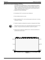
Rack Mount — The 3U x 19" System 8/10 PLUS enclosure is ready for rack
mounting.
1-3
Extron • System 8/10 PLUS • User’s Manual
Introduction to System 8/10 PLUS
Specifications
Specifications
General
Power ..... 90 - 260 VAC, 50/60 Hz, SMPS
Power consumption ..... 20 watts
Dimensions ..... 17" W, 10.5" D, 5.1" H
Shipping Weight ..... 18 lbs
Operating Temperature ..... 0° C - 50° C
Storage Temperature ..... -20° C - 70° C
MTBF (demonstrated) ..... 30,000 Hours
Approval ..... UL Listed
Warranty ..... 2 years parts and labor
Wideband Video
Connectors ..... BNC
Bandwidth, System 8 ..... 300 MHz (-3 dB)
Bandwidth, System 10 ..... 250 MHz (-3 dB)
Crosstalk at 10 MHz ..... -35 dB (typical) (note 1)
Isolation at 10 MHz ..... 55 dB (typical) (note 2)
Return Loss at 10 MHz ..... 25 dB
Input Impedance ..... 75 Ω
Output Impedance ..... 75 Ω
Termination Impedance ..... 75 Ω
Gain ..... 0 dB
Composite/S-Video
Connectors ..... BNC
Termination impedance ..... 75 Ω
Gain ..... 0 dB
Sync
Connectors ..... BNC
Termination impedance ..... 510 Ω
Triple action switch delay ..... 0 - 7.5 seconds
Audio
Input Impedance ..... High Z (>10k Ω, typical)
Input Voltage Level ..... To 10 V p-p into 600 Ω
Output Impedance ..... Low, capable of driving 600 Ω
Crosstalk ..... -100 dB @ 1 kHz (note 1)
Signal-to-Noise Ratio ..... >95 dB
Single Output Level ..... Near zero to unity gain
Differential Output Level
..... Near zero to +6 dB gain
Bandwidth ..... 20 Hz - 20 kHz
Connectors ..... Phoenix® type with captive screws
_____ 1. The Crosstalk specification is the attenuation of all hostile signals relative to a
given input-output connection.
2. The Isolation specification is the attenuation of an input signal relative to an
unselected output when all inputs have the same signal applied simultaneously.
Extron • System 8/10 PLUS • User’s Manual
1-4
Introduction to System 8/10 PLUS
Packing List
Packing List
The following items are included with your System 8/10 PLUS switcher:
• System 8 (or 10) PLUS switcher
• Communications Adapter
The Comm adapter allows the System 8/10 to be connected to the projector.
This adapter is per customer order. Because each comm adapter is
customized for the application, they appear different.
• CC-50' Cable
Communications extension cable (50 feet)
• Power Cord
Connects AC power to the System 8/10 PLUS
• RJ11 Cable (telephone type)
This is only for use when looping System 8/10 PLUS switchers in a master/
slave configuration.
• Phoenix® Audio Connectors
There will be 9 with each System 8 PLUS or 11 with each System 10 PLUS.
• System 8 (or 10) PLUS Switcher User’s Manual (this manual)
• Extron tweaker
This is a small, combination screwdriver used for tightening connector
screws and for making adjustments.
Appendix B has a list of other related part numbers if other adapters or cables
are needed.
1-5
Extron • System 8/10 PLUS • User’s Manual
System 8/10 PLUS Switcher
User’s Manual
2
Chapter Two
Rear Panel Connections
input and Output Connections
Audio Connections
Configuring for RGBS
Configuring for Composite Video & S-Video
Video Loop Back (VLB)
Rack Mounting
General
Rear Panel Connections
Rear Panel Overview
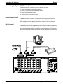
This chapter covers the types of input and output connections, switches and
indicators on the rear panel of the System 8/10 PLUS.
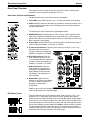
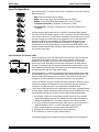
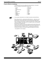
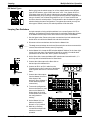
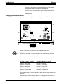
Rear Panel Controls and Indicators
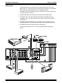
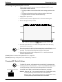
The following list refers to each input channel (left diagram):
1. Input LEDs: Green LED indicator (1-8 or 1-10) lights to indicate selected input.
2. Audio Level: An audio level attenuator is provided for each input channel (1-8 or
1-10) to normalize audio output levels. The attenuators can only decrease (not
increase) audio levels.
The following are in the output section (right diagram below):
3. NORM/VLB Switch: Set this switch to “VLB” to select Video Loop Back mode
when using composite-to-RGB decoder or scan doubler (e.g., Extron Andora).
Set switch to “Norm” for normal operation. Refer to the discussion of Video Loop
Back mode later in this chapter.
4. Output LEDs: Green LED indicator (3 locations) lights to indicate which type of
output is selected. (RGBHV, Composite, or S-Video).
5. S-Video/S-VHS Switches: Used only when setting up an input. (1-8 or 1-10)
Separate switch for each input
channel to select input/output type
(RGBHV, Composite, or S-Video).
6. NTSC/PAL Switches: Used only
when setting up an input. (1-8 or
1-10) Separate switch for each input
channel to select input/output type
(RGBHV, Composite, or S-Video).
7. Address Switches: Used only
when setting up a master/slave
configuration. Setting determines
binary address of slave switcher.
See Chapter 5 for looping two or
more switchers.
8. Master LED: Lights when this
switcher is configured as the Master
in a loop, or when the switcher is
operating in a stand-alone
configuration.
Details on the function of each panel
section is described on the following pages.
DIP Switch Types
There are different types of DIP switches, some “slide” and some “rock”. Your
System 8/10 PLUS could have either type DIP switch. Although they operate
differently and are labeled differently, they are simply On (switch closed) or Off
(switch open). In the example diagram on the left, with the slide-type DIP switch,
move the slide up to set the switch On (closed). With the rocker-type DIP switch
shown in this example, press the top rocker down to set the switch On (closed).
The two example switches shown here are set up for the same configuration.
Throughout this manual, you may see either type of switch, however, the switch
positions will be the same regardless of the switch type.
2-1
Extron • System 8/10 PLUS • User’s Manual
General
Rear Panel Connections
Input Section
Each input channel of the System 8/10 PLUS has the following:
• A set of five BNC connectors mounted vertically.
• A six-pin audio connector located below each set of BNC connectors.
• A green LED indicator above each set of BNC connectors ( ) lights to
indicate that this input is selected. (Only one input can be selected at a time.)
With this combination of input connectors, the System 8/10 PLUS can accept any
type of video input format (NTSC/PAL, S-Video/S-VHS or RGBS). Also, each
input can have stereo audio. The System 8/10 PLUS handles signals according to
how they are connected to the input, as well as how the configuration DIP
switches are set. Each type of setup is explained in detail later in this chapter.
When the System 8/10 PLUS is used to switch different types of signals, the
output signal will have the same format as the selected input. That is, RGB and
Sync (composite or separate H&V) will exit through the RGB and Sync output.
Likewise, NTSC and PAL video signals go to the Composite Video output.
Therefore, if multiple signal types are used in the same switcher, the same
multiple outputs must be used by the projector or display monitor. Some displays
receive all signals on the RGBHV port when under switcher control (see the
appropriate connection diagram in Chapter 3 for your projector).
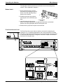
Output Section
The System 8/10 PLUS has three sets of
output connectors, one for each video
format: RGBS, S-Video/S-VHS (Y/C) and
NTSC/PAL (composite video). There is a
green LED to identify which output is active,
as determined by which type of input is
selected. There is also a 6-pin audio output
connector at the bottom, as well as left and
right audio BNC outputs.
_____ If audio comes in on BNC connectors, it
goes out the BNC connectors; if it comes in
on the 9-pin Phoenix® connector, it goes out
the 9-pin Phoenix connector.
Video Loop Back (VLB)
When using Extron’s Sentosa, Lancia, a third-party scan converter or a
Composite/S-Video-to-RGB decoder, the System 8/10 PLUS allows the use of a
single scan-doubler or decoder with multiple switcher inputs to be looped back
through the System 8/10 PLUS and then out again as RGB Sync together with all
other RGB Sync inputs. These video configurations are described in detail later
in this chapter.
Power
Although the power cord connector is on the back panel, the fuse is actually on
the power supply inside the cabinet. System 8/10 PLUS switchers have power
supplies that accept 90-260 VAC, 50/60 Hz line power. No power configuration is
required. The fuse rating is 250 VAC, 2 Amp fast-blow.
Extron • System 8/10 PLUS • User’s Manual
2-2
Rear Panel Connections
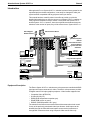
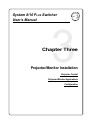
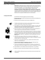
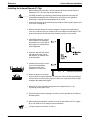
Applications
Applications
The illustration shows examples of some of the equipment that can be connected
to a System 8/10 PLUS switcher.
2-3
Extron • System 8/10 PLUS • User’s Manual
Video Input
Rear Panel Connections
Input Configurations
Each System 8/10 PLUS switcher input can be configured for any of the following
RGB connections:
•
•
•
•
•
RGB - Red, Green/sync, Blue (3 cables)
RGBS - Red, Green, Blue, and Composite Sync (4 cables)
RGBHV - Red, Green, Blue and Separate H & V Sync (5 cables)
Composite (NTSC/PAL) - Using the G connector (1 cable)
S-Video/S-VHS - Using the G connector for Y and H/HV connector for C
(2 cables)
All video inputs to the System 8/10 PLUS use BNC connectors. Many types of
video devices (VCR, laserdisc players, some computers, etc.) do not have BNC
video output connectors. For this reason, an adapter may be required to connect
the device output to the BNC input of the System 8/10 PLUS. (See parts list in
Appendix B.) With the proper adapter, the RGBS signal can be connected
directly to the R, G, B, H and V inputs of the switcher. If the RGB signal is
carrying the sync on the green channel, connect the three RGB cables to the
switcher without using the sync channels. Audio connections may be used with
any of these video inputs.
Input Switches and Output LEDs
When configuring an input, the video mode must be set up in the DIP switches
located above the output connectors. There are two banks of eight (or ten)
switches. The left bank is for S-Video and the right bank is for Composite
(NTSC/PAL) video. One switch in each bank is assigned to an input channel
number. For example, input #1 uses the leftmost switch at each bank. For the
video mode shown on this page, DIP switch #1 of each switch bank must be in
the RGBS position, which is in the down position.
The System 8/10 PLUS switchers are shipped with all DIP switches in the down
position (RGBS inputs). For composite video input, change the NTSC/PAL DIP
switch for that input channel to the up position. For S-Video or S-VHS input,
change the S-Video/S-VHS DIP for that input channel to the up position.
There is an Output LED next to each set of output connectors. When an input is
selected, the Output LED indicates the format for which that input has been
configured. This also informs the user which output should be used.
_____ These output LEDs also serve as a configuration check. Also, for displays which
have all of their signals (including S-video and Video) on the RGBHV port, both
the RGB LED and either the S-video or Video LED will light simultaneously.
1. For example, if input #1 is using RGBS, and DIP switch #1 of the S-Video
bank was accidently switched “up”, then the S-Video output LED will be lit,
instead of the RGBS LED. This informs the user of an improper setting.
2. The only conditions for which two output LEDs can be lit at the same time is
when the System 8/10 PLUS is used in the Video Loopback mode.
3. Under normal conditions, one of the output LEDs should be lit.
4. All three output LEDs should never be lit at the same time.
5. If no LEDs are lit, check for proper switch settings.
The following pages show examples of the three possible input configurations.
Extron • System 8/10 PLUS • User’s Manual
2-4
Video Output
Rear Panel Connections
Video Output Connections
The System 8/10 PLUS has three sets of BNC output connectors (RGBHV,
Composite, and S-Video). Which output connectors are active depends upon
which type of input is selected. These connectors provide outputs from the
System 8/10 PLUS to the video projector or display monitor. When an input
channel is selected, the corresponding LED lights to show the format of the
selected video and which output is being used.
Only one output can be active at any given moment, unless the VLB (Video Loop
Back) feature is being used.
All output signals have the same format as the selected input. They are switched
to the output unaltered. That is: RGBHV input signals are RGBHV output signals,
composite video input signals are composite output signals, and S-Video input
signals are S-Video output signals. Thus, if multiple input signal types are used,
such as audio on the R and B inputs, the same multiple output signals will be on
the corresponding output to the projector or display monitor.
1. LED Output Indicators (See in figure above.)
An LED lights to identify which of the three outputs is currently being used.
2. RGB Output Connections ( )
Attach BNC cables to outputs labeled “R”, “G”, “B”, “H/HV”, and “V”.
3. Composite Video Output Connections ( )
Attach a single BNC cable to the output marked “Video”.
4. S-Video Output Connections ( )
Attach the Y (luminance) cable to the BNC connector marked “Y” in the S-Video
section and the C (chroma) cable to the BNC connector marked “C”.
5. If the audio for the selected channel uses the Phoenix® input connector, then the
audio output must use the Phoenix output connector ( ). See next page.
2-5
Extron • System 8/10 PLUS • User’s Manual
Audio Input/Output
Rear Panel Connections
Audio Connections
The System 8/10 PLUS can accept audio from two different sets of input
connectors. Left and right audio can use the R and B BNC connectors shown to
the left (labeled R Audio and L Audio). Audio can also use the 6-pin Phoenix®
brand of captive screw connector shown at the bottom of each input and output.
Audio connections can be made using the Phoenix
terminals in the following ways:
• Unbalanced High Impedance Stereo Tip, Ring, Ground
(Left & Right)
• Balanced High Impedance Stereo Tip, Ring (Left &
Right)
• Balanced 600 ohm Impedance Stereo Tip, Ring (Left &
Right)
TIP
SLEEVE
TIP +
RING
-
TIP RING
SLEEVE
SLEEVE
Right and left audio ports are available on both BNC connectors and on
6-terminal screw Phoenix connectors. BNC audio outputs are available only
when using Composite Video or S-Video sources. When using the BNC input
ports for audio, any unselected audio port will be terminated at 75 ohms. Verify
that this termination will not damage the output.
An audio level attenuator is located to the right of each bottom BNC input
channel connector. The attenuators are used to adjust only the audio levels
going to the Phoenix connector output, and not those going to the BNC outputs.
Because attenuators can only decrease (not increase) the audio levels, initial
adjustments should be made with the attenuators set to the maximum
(clockwise) position.
The captive connectors are located on the rear panel, just below the BNC
connectors, and are labeled “R” (right) and “L” (left) for each channel. When
wiring these Phoenix connectors and inserting them into the System 8/10 PLUS
switcher, remember that the screw heads must face downward. Use the
following diagrams to wire the connectors for your audio inputs and outputs.
_______ Because all switching is one-to-one, the audio output must use the same
connector type(s) as the input (Phoenix to Phoenix or R/L Audio to R/L Audio).
600 ohm resistors, .25 W
_____ Nine audio connectors are shipped with each System 8 PLUS and eleven with
each System 10 PLUS. If more are needed, use Phoenix® audio connectors,
Extron part number 10-163-01.
Extron • System 8/10 PLUS • User’s Manual
2-6
RGB Input
Rear Panel Connections
RGB (Analog) Input Connections
Each switcher input can be configured for any of the following RGB connections:
• RGB - Red, Green/sync, Blue (3-cables)
• RGBS - Red, Green, Blue, and Composite Sync (4-cables)
• RGBHV - Red, Green, Blue, H & V Sync (5-cables)
Any of these inputs may include audio follow, using the Phoenix® audio
connectors. If the video source does not have audio, audio can be connected
from another source.
Input Selection Switches
To complete the RGB configuration, be sure that both of the DIP switches for
that input channel are in the down position. Audio may be connected to the
Phoenix connector at the bottom of that input section. See page 2-6 for details
on audio connections.
When the System 8/10 PLUS selects this input, the LED next to the output
marked “RGBS” will light.
2-7
Extron • System 8/10 PLUS • User’s Manual
NTSC/PAL Input
Rear Panel Connections
Composite Video (NTSC/PAL) Input Connections
NTSC (National Television Standards Committee) and PAL (Phase Alternate
Line) composite video signals use a single coax cable. They may or may not
have separate audio.
See the illustration below to connect a composite video source to the input of a
System 8/10 PLUS. If the source has stereo audio, it can be connected either of
two ways. The solid line shows the use of a Phoenix® audio connector that has
six (6) conductors. Details on audio connections are given on page 2-6. The
second method of audio input connection is shown by dashed lines, and is also
explained on page 2-6.
Input Selection Switches
To complete the Composite Video configuration, the DIP switch for the input
number being configured must be in the up position. These switches are on the
right side of the rear panel. The switch for the example (input #4) is shown in the
NTSC/PAL position. The S-Video switch for this channel (input #4) must be in
the down position.
When the System 8/10 PLUS selects this input, the LED next to the output
marked “Video” will light. See arrow in illustration below.
_______ If audio input uses the Phoenix connector, the output must also use the Phoenix
connector. If the input uses BNC connectors, the output must also use BNC
connectors.
Extron • System 8/10 PLUS • User’s Manual
2-8
S-Video Input
Rear Panel Connections
S-Video Input Connections
S-Video or S-VHS is typically an output from the AV source on a 4-pin miniature
DIN type connector which must be converted to 2 BNC type connectors – one for
chrominance (C) and the other for luminance (Y) - [Extron adapter cable 26-35301]. S-Video input to the System 8/10 PLUS is made by connecting the chroma
(C) to the H/HV/C input connector and the luminance (Y) to the G/Video/Y input
connector. Audio inputs from the AV source are made to either the R & L inputs
of the System 8/10 PLUS or to the R/R-Audio and B/L-Audio BNC connectors.
Input Selection Switches
Each input must be configured. This is done by setting the DIP switches located
above the output connectors. There are two banks of DIP switches, each having
8 (or 10) switches. Each input channel has two switches assigned to it, one in
each bank. For example, input #3 uses the third switch at each bank. For the SVideo input shown below (S-Video signal connected to channel 3 input), the #3
DIP switch of S-Video/S-VHS bank should be in the up (Video) position and the
#3 DIP switch of the NTSC/PAL should be in the down (RGBS) position.
Place the S-Video/S-VHS switch for the input channel being configured in the
Video (up) position. The NTSC/PAL switch for this channel (input 3, in this
example) must be in the down position.
When the System 8/10 PLUS selects this input, the LED next to the output
marked “S-Video” will light. See arrow in illustration below.
_______ If audio input uses the Phoenix connector, the output must also use the Phoenix
connector. If the input uses BNC connectors, the output must also use BNC
connectors.
2-9
Extron • System 8/10 PLUS • User’s Manual
Video Loop Back
Rear Panel Connections
Video Loop Back (VLB)
Video Loop Back (VLB) is a special feature which allows a scan doubler (also
called “line-doubler”) or an RGB decoder to be used with the System 8/10 PLUS
switcher. With VLB enabled, any input can use an RGB decoder or a scan
doubler without recabling. This reduces the amount of equipment needed for a
system that requires the use of either of these devices.
The VLB mode is turned on and off by a toggle switch located between output
connectors on the right, rear panel of the System 8/10 PLUS. With the switch in
the NORM (up) position, the VLB mode is disabled. In the VLB (down) position,
Video Loop Back is enabled.
To configure the System 8/10 Switcher for Video Loop Back, connect the
Composite video or S-video output(s) source to a System 8/10 PLUS input.
Connect the output of the System 8/10 PLUS S-Video and/or Composite video to
the input of the decoder or line doubler. Then connect the RGBS output of the
decoder or scan doubler to the last input of the switcher. Only the last input can
be used as VLB input. That is, input #8 of the System 8 PLUS, or input #10 of the
System 10 PLUS.
_____ When connected for Video Loop Back, the number of usable inputs is reduced
by one because VLB uses the last input.
Normal Mode
The VLB switch is set to NORM and no decoder or scan doubler is connected.
When Composite and S-Video input signals are selected, they are routed directly
to the projector (or display monitor) through the normal Composite and S-Video
output connector set.
VLB Mode
Set this switch to the “VLB” position when an external decoder or scan doubler is
connected, as pictured on the following page. When a Composite or S-Video
input signal is selected, it goes through the normal Composite or S-Video output
connectors to an external (user provided) Composite-to-RGB decoder or scan
doubler. The RGBS output of the decoder or scan doubler is “looped back” to the
last input of the System 8/10 PLUS. The decoded (or scan doubled) RGBS signal
is then routed directly to the projector (or display monitor) from the System 8/10
PLUS RGBS output connectors (see diagram on the following page).
Optional Extron Products that can be used with a System 8/10 Plus in Loop Back
mode include:
• CD 400 – Quad Standard Decoder
• Lancia – NTSC & PAL Scan Doubler
• Sentosa – High Resolution Video Line-Quadrupler
60-145-01/02
60-213-01
60-229-01
VLB Restrictions
• When using the VLB mode with multiple switchers, always connect the
switchers in a Star Configuration. The VLB mode cannot be used when
switchers are connected in a Daisy-Chain configuration.
• Only the master switcher can use the VLB mode (slave switchers cannot).
• Refer to Chapter 5 for instructions on looping switchers in the Star
Configuration.
• For projectors that accept S-video and Composite video signals on their
RGBHV port, VLB can only be used when the System 8/10 PLUS is no longer
in cable saver mode (see page 3-4 for SW settings).
Extron • System 8/10 PLUS • User’s Manual
2-10
Video Loop Back
Rear Panel Connections
VLB Operation
The illustration below is an example of a decoder being used in Video Loop
Back, however, it could be any one of several types of decoders or line doublers.
When VLB is active, the System 8/10 PLUS operates as follows:
1. Composite video and S-Video sources are connected to any of the System 8/10
PLUS inputs except the last one.
2. Standard RGB inputs exit the switcher through the normal RGB output.
3. Composite Video or S-Video signals exit the switcher through their normal
Composite video or S-Video outputs and are routed to the external decoder or
scan doubler.
4. The RGBS output of the decoder or scan doubler is then “looped back” to the
last input (input #8 or #10) of the switcher, which is selected at the same time.
5. The RGBS output from the switcher goes to the projector.
This allows the System 8/10 PLUS to route only RGB signals to the display
device.
2-11
Extron • System 8/10 PLUS • User’s Manual
Special Features
Rear Panel Connections
Special Features
The System 8/10 PLUS has some special features, one of which is Auto Sync
Detect. Auto Sync Detect determines what type of RGB sync is being input.
Sometimes this feature must be disabled when connecting to certain projectors.
For example, if a Barco projector is powered up with no input yet present at the
switcher, the projector will not detect any sync and will default to sync on Green.
Later, if an RGB source with separate sync is connected to the System 8/10
PLUS, the Barco projector, which is still expecting sync on Green, may
experience problems dealing with this conflicting situation. However, by setting
both Input Selection DIP switches up (disabled), the switcher will disable Auto
Sync Detect which will communicate to the projector that the RGB input has
separate sync. Similarly, if Auto Sync Detect is enabled (both DIP switches
down) for an RGB input, the switcher communicates to the projector that the
RGB input has sync on Green.
Input Selection Switches
Each input must be configured. This is done by setting the DIP switches located
above the output connectors. There are two banks of DIP switches, each having
8 (or 10) switches. Each input channel has two switches assigned to it, one in
each bank. For example, input #2 uses the second switch at each bank. By
setting input #2 up in both banks, the Auto Sync Detect feature will be disabled
and the RGB sync will be defined as separate sync (as described above).
Extron • System 8/10 PLUS • User’s Manual
2-12
Rack Mounting
Rear Panel Connections
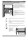
Cabling a System 8/10 PLUS in a Rack
When routing cables from one unit to another in a rack,
do NOT allow the cables to pull down on the
equipment. Use “Tie Wraps”, “Rip-Ties” or other
devices to secure the cables at some location in the
rack that is above the rear panel connectors. Loosely
hanging cables may be stepped on, resulting in
damage to cables and equipment, as well as injury to
personnel.
The illustration shows the rear view of a system rack.
The example has the cables tied to the rack above the
connections to the equipment. This allows a clear view
of the back panels and prevents the cable weight from
pulling down on the equipment.
_______ The holes in the top and bottom of the System 8/10 PLUS enclosure are for
cooling. Do NOT cover these holes. This could cause overheating of vital
components.
_______ Maximum ambient operating temperature must not exceed 104° F (40° C).
_______ The mounting rack and all equipment mounted in it must be grounded according
to national and local electrical codes.
_____ Keep power and signal cables separate (power cables on the right and signal
cables on the left.)
(French)
Câbler un Système 8/10 PLUS sur un rack - page B-10
(German)
Verkabelung vom System 8/10 PLUS innerhalb eines
Gestells - seite B-12
2-13
Extron • System 8/10 PLUS • User’s Manual
System
System 8/10
8/10 P
PLUS
LUS Switcher
Switcher
User’s
User’s Manual
Manual
1
3
Chapter Three
Chapter One
Introduction
to System
8/10 PLUS
Projector/Monitor
Installation
Equipment Description
Projector
Control
Configurations
Projector/Monitor Applications
Features
Configuration
Specifications
General
Projector/Monitor Installation
Projector/Monitor Installation
The System 8/10 Plus can be configured for many projectors. Among the
projector manufacturers which Extron supports are:
•
•
•
•
•
•
•
•
•
Ampro
Barco
Digital Projection
Eiki
Electrohome
Epson
Hughes/JVC
InFocus
Mitsubishi
•
•
•
•
•
•
•
•
NEC/Runco
Panasonic
Sanyo
Seleco
Sharp
Sony
Toshiba
Zenith
_____ If your projector manufacturer is not listed here, please consult with Extron.
Extron System 8/10 PLUS switchers have bidirectional (i.e., "talk-listen"), userprogrammable communications that communicates with the displays listed
above. If projector input selection is made by the hard-wired or infrared remote
control of the display*, the System 8/10 PLUS switcher "listens" to the selection
and switches to the proper input.
When an input selection is made at the switcher (by a front panel button, hardwired remote control, RS-232 communications or IR-30), the System 8/10 PLUS
switches the projector to RGBS, S-Video, or Composite (as required) and
commands the projector to load the pre-programmed presets for that input.
* not applicable on some displays
3-1
Extron • System 8/10 PLUS • User’s Manual
Cables
Projector/Monitor Installation
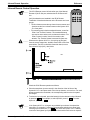
Projector Control Port
The projector control port is a 15-pin HD
connector located at the upper right
hand corner of the rear panel.
A Communications Cable (CC) is used
to connect the System 8/10 PLUS to the
projector, or to a suitable
communications adapter. The cable is
CL-2 rated and is available in three
lengths, listed below.
Cable Length Extron Part Number
CC-50' 50 ft.
26-305-01
CC-100' 100 ft.
26-305-02
CC-200' 200 ft.
26-305-03
User-Supplied Communications Cables
For custom installations, you may choose to make your own communications
cables. If so, be sure to use approved installation practices, such as:
• Installation requires plenum rated cables
• Cables will be run through conduit
If you wish to make your own communications cables (up to 200 feet in length),
using 26-AWG twisted pair cabling, follow the pin-to-pin wiring illustrated below.
The first illustration is for a Standard Communications cable with 15-pin male to
9-pin female connectors.
200 Ft (max)
15-PIN
HD FEMALE
Extron
System 8/10
Switcher
15-PIN
HD MALE
9-PIN
D-SUB FEMALE
1
2
3
4
5
6
1
2
3
4
5
6
7
8
7
8
9-PIN
D-SUB MALE
Extron
Communications
Adapter
9
15
The second illustration is for a Type II Communications cable with 15-pin male to
15-pin female connectors. This cable is required for certain installations, for
example, when using the Ampro Type II adapter, etc.
Extron • System 8/10 PLUS • User’s Manual
3-2
Comm Adapters
Projector/Monitor Installation
200 Ft (max)
15-PIN
D-SUB FEMALE
15-PIN
MALE
Ampro
HOST
connector
15-PIN
D-SUB FEMALE
1
1
2
2
3
3
4
4
5
5
6
6
7
7
8
8
9
9
10
10
11
11
12
12
13
13
14
14
15
15
15-PIN
D-SUB MALE
Extron
Communications
Adapter
Type II
Stand Alone Operation
If you plan to use your System 8/10 PLUS in a system where it will not be
connected to a projector, it must be configured for RS-232 mode. The switcher
settings are shown on the following page.
Address Switch Settings
For installations with one switcher, configure the System 8/10 PLUS as a master
switcher by setting the address switch on the rear panel. If multiple switchers are
being used in a master/slave configuration, refer to Chapter 5.
Configuration Setup
System 8/10 PLUS switchers are shipped from the Extron factory configured for
the projector brand specified by the user at the time of the order.
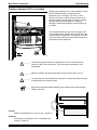
Labels are placed in three locations:
1. On the shipping container
2. On the rear panel
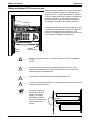
3. Inside the front panel access cover lower left (See picture on next page.)
Switcher configuration is done with switch settings behind the front access panel.
Information is printed on a label inside the front panel access cover for setting up
most applications. The label includes a place for the user to mark the
configuration for which the System 8/10 PLUS is set.
This chapter covers the setup and installation of the System 8/10 PLUS with
specific projectors and displays. This includes instructions for changing the
configuration switches. If your application includes connecting more than one
switcher, you will also need to refer to Chapter 5.
Removing the Access Cover
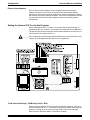
If it is necessary to check or change any configuration switches, the Front Panel
Access Cover must be removed. This is done with a small, flat-blade
screwdriver.
_____ Do NOT touch the IC chips!
3-3
Extron • System 8/10 PLUS • User’s Manual
Configuration
Projector/Monitor Installation
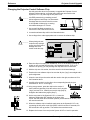
Extron Comm Adapters
Extron communications adapters (Comm Adapters) provide the interface
between the 9-pin connector of the communications cable and the display’s
switcher port. Extron manufactures a wide range of Comm Adapters to interface
with virtually all projector makes and models. Your Extron representative will help
you select the correct Extron Comm Adapter to meet your specific projector
requirements.
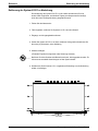
Setting the System 8/10 PLUS for the Projector
Before each System 8/10 PLUS ships, it is configured for the projector type as
requested by the user. However, it can easily be reconfigured for any application.
The picture below shows the function of each switch behind the access cover on
the front panel of the System 8/10 PLUS.
______ Do not change any switch settings without following the correct procedure in this
chapter. Go to the appropriate procedure for your application.
Triple-Action Switching™ (RGB Delay Switch - RS5)
When an input is selected, the sync switches immediately. However, the picture
may be switched later (0.0 - 7.5 seconds) to prevent an unstable image while the
projector is setting up for the new sync signal. RS5 is used to set this delay.
Each position of the switch adds 0.5 seconds to the delay.
Extron • System 8/10 PLUS • User’s Manual
3-4
Projector/Monitor Installation
_____ Notes
3-5
Extron • System 8/10 PLUS • User’s Manual
System 8/10 PLUS Switcher
User’s Manual
4
Chapter Four
Rear Panel Connections
Remote Controls
Front Panel
Button Labels
Controlling the Switcher
General
Controlling the System 8/10 PLUS Switchers
The System 8/10 PLUS Switchers can be controlled four ways:
1. Manual front panel controls (See next page.)
2. Manual, (contact closure) wired remote control
3. Manual infrared remote control
4. RS-232 control (from a host system)
Manual Remote Control
The Manual Remote connector can be used to select inputs by means of dry
momentary contact closures and Tally outputs to drive (user provided) remote
LEDs to indicate which of the inputs have been selected. This is described in
detail on page B-1 of the appendix.
RS-232 Control
The RS-232 Comm connector provides a serial interface for switching inputs by
means of a host computer (such as a PC) or other third party control system,
such as Crestron® or AMX®. For example, a control program in a PC could be
written in a DOS or Windows® environment. RS-232 programming is described
in Appendix A.
S-VIDEO
4-1
Extron • System 8/10 PLUS • User’s Manual
Front Panel
Controlling the Switcher
Front Panel Buttons and Indicators
The following Front Panel Controls are used to operate the System 8/10 PLUS.
Power indicator – Lights to indicate System 8/10 PLUS switcher input power is On.
This LED also blinks when the optional IR-30 remote receiver is detecting a
signal from the transmitter.
Display Power Button – This button is used to turn the projector ON or OFF. To
turn the projector ON, press this button down until it flashes on, then off,
(approximately two seconds) and then release the button. Some projectors take
a few seconds to initialize. For those projectors, the Display Power button will
flash to prevent any communications during the initialization period. This flashing
can last from 8 to 35 seconds. To turn OFF the projector, press and hold the
button down until it flashes off, then on (approximately two seconds). This two
second delay provides a safety factor so the projector is not turned off by
accidentally touching this button.
Display Mute Button – The Video Mute button is similar to a “Projector Mute” or
“Pause” button typically found on the projector remote control. This button mutes
(blanks) the projector display, but does not actually turn the projector off. Press
to mute the video display. The button lights to indicate Display Mute mode has
been selected and the projector display is blanked. Press the button again to
restore the video image.
RGB Mute – Pressing this button interrupts the picture (RGB) to the display device,
but not the sync. Pressing the button again restores the picture without flicker.
Audio Mute – Press to mute the audio. The button lights to indicate audio mute
mode has been selected. Press again to restore the audio. The button light then
goes out.
Input Select Buttons – Press to select video input. (System 8 has buttons 1-8 and
System 10 has 1-10.) Each button lights when its input is selected. Only one
input can be selected at one time. These buttons flash to indicate that audio only
is selected from that input (Breakaway).
Infrared Receiver – The lower left corner of the front panel has the receiver lens for
the infrared (IR System Remote) control. Although the lens is there, it will not
operate if the option is not installed. See page B-5 for installation procedures and
B-6 for IR operation.
Infrared Remote Transmitter – This remote control transmits commands to the
Infrared Receiver described above.
SYSTEM REMOTE
Extron • System 8/10 PLUS • User’s Manual
4-2
Controlling the Switcher
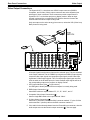
Miscellaneous
The right side of the front panel has a removable cover for accessing setup
controls. This is explained in Chapter 3.
Button Labels
1. Remove the desired key cap from
the switcher by grasping the top and
bottom of the key cap and pulling it
away from the switcher.
2. Dismantle the button by prying the
clear legend cover from the key cap
base.
LEGEND
PLATE
KEY CAP
CLEAR LEGEND
COVER
3. Label the button by using rub-on
letters on the white legend plate or by placing a small clear or white label
between the white legend plate and the clear legend cover.
4. Reinsert the key cap back into place on the switcher.
Front Panel Access Cover
The Front Panel has a cover that can easily be removed for configuring the
System 8/10 PLUS for different applications. Use a small screwdriver to release
the captive screws that hold the access cover on. Note that the cover has a label
on the inside that shows how to configure the switches. Chapter 3 has detailed
instructions for using this area.
J2
U3
U1
J3
4-3
Extron • System 8/10 PLUS • User’s Manual
Multiple Switcher Operation
System 8/10 PLUS Switcher
User’s Manual
5
Chapter Five
Multiple Switcher Operation
Two Switcher Operation
Daisy Chain Connection
Star Connection
Looping with System 4xi
Extron • System 8/10 PLUS • User’s Manual
Looping
Multiple Switcher Operation
Multiple Switcher Installation
This chapter shows how to connect multiple switchers in the following ways:
•
•
•
•
Two Switcher Operation
Daisy Chain Connections
Star Connections
Using System 8/10 PLUS as slave(s) to System 4
For large installations that require more inputs than one system switcher can
handle, multiple switchers can be looped together. Up to 17 switchers can be
looped together, providing a total of 154 inputs (using all System 10 PLUS
switchers). System 8/10 PLUS switchers can be looped together in different
combinations. Two connection schemes that are suitable for looping switchers
are called Daisy Chain and Star configurations.
When switchers are connected to work together, only one can communicate with
the projector and with the host system. This switcher is called the "Master". All
other switchers provide input to the Master, and they are called “Slaves”. Which
switcher operates as the Master is determined by two things:
1. How the cables are connected
2. How the Address switches are set
After a multiple switcher configuration is complete, the information must be
saved to the master switcher’s memory.
Saving Configurations to Memory
The System 8/10 PLUS has a memory to store the current connection scheme
(configuration). To save the configuration to memory, switch #4 of the Address
DIP switch, located on the rear panel of the Master Unit, must be set to the
Configuration (Down) position and the system operated for a minimum of 10
seconds. This provides sufficient time to save the configuration in the memory of
the Master Unit. After the configuration is saved, Address switch #4 is set to the
Normal (Up) position. The configuration sequence does not have to be repeated
until (or unless) the connection scheme is changed. This procedure will be
included as a step in the procedures that follow.
Master/Slave Configurations
The Star connection method (shown to the left) provides increased flexibility and
higher video performance than the Daisy Chain connection method. The
maximum number of inputs, however, is limited to 100 inputs when all switchers
are System 10 (1 master unit plus 10 slave units). If
using all System 8 switchers, the maximum number of
inputs is 64 (1 master unit and 8 slaves).
Inputs 1 - 10
Slaves #3 - 9
A simple example of the Daisy Chain method of
connection is shown to the right. It is the most
common looping method used for large analog RGB
switching systems. This method offers the largest
chaining configuration – 154 inputs when using all
System 10 switchers (1 master unit plus 16 slave
units). If using all System 8 switchers, the
maximum number of inputs is 120.
Daisy Chain
Configuration
Inouts 1 - 9
For information on selecting slave channels with
the optional IR remote, see page B-6.
Inputs 11 - 20
Inputs 91 - 100
5-1
Extron • System 8/10 PLUS • User’s Manual
Multiple Switcher Operation
Looping
DIP Switch Types
Before going into the switch setups, let us first explain that there are different
types of DIP switches, some "slide" and some "rock". Your System 8/10 PLUS
could have either type DIP switch. Although they operate differently and are
labeled differently, they are simply on/off (open/closed) switches. Regardless of
the type of switch, we will show the positions as "up" or "down" and will use
arrows to show the switch position. The illustration to the left shows two types of
switches having the same configuration. Throughout this manual you may see
either type of switch, however, the switch positions will be the same.
Looping Two Switchers
A simple example of using multiple switchers is to use two System 8/10 PLUS
switchers. As explained on the previous page, the switcher feeding the projector
is the Master and the output of the Slave is one of the inputs to the Master.
1. See the figure below. Remove the power connections from both switchers and
decide which unit will be the Master Unit and which the Slave.
2. Disconnect all communications devices from the Master Unit.
_____ The only communications device that a Slave switcher can have connected is a
contact closure Manual Remote control (if required).
3. On the Master Unit, locate the DIP switches labeled "Address" in the lower right
corner of the rear panel. Set switches #3 and #5 up, and #1, #2 and #4 down.
(Switch #4 must be set to the "down" position until Step 9.)
4. On the Slave Unit, locate the Address DIP switches and set switches #1, 2, 3
and 4 up, and set switch #5 down for Slave Mode.
5. Connect the video output of the Slave Unit to
the last input of the Master Unit.
6. Connect an RJ11-to-RJ11 cable from the
"System Intercom Out" connector of the Master
to the "System Intercom In" connector of the
Slave.
Address
(#0)
7. Connect the video outputs
from the Master Unit to the
video inputs of the
projector. (Go to Chapter 3
for the detailed projector
connections.)
8. To save the configuration
first turn the Slave On, and
then turn the Master On.
Wait at least 10 seconds
for the Master Unit to save
the configuration to
memory.
1 2 3 4 5
9. On the Master Unit, set
Address switch #4 to
Normal, or "Up" position.
10. Make any necessary
connections and put both
switchers to normal
operation.
Extron • System 8/10 PLUS • User’s Manual
1 2 3 4 5
5-2
Multiple Switcher Operation
Daisy Chain Configuration
Daisy Chain Connection
Daisy Chain configuration refers to routing the output of the first slave (#0) into
the last input of the master switcher, and the output of the second slave (#1) into
the last input of slave #0... etc. All other inputs are used for various video
sources. The maximum number of inputs available in the daisy-chain
configuration is 154 when using all System 10 PLUS switchers (120 when using
all System 8 switchers). The Daisy Chain configuration is easy to configure, but
results in decreased system bandwidth due to the cascading signal path through
multiple switchers. As a further limitation of this connection scheme, it does not
allow the use of composite-to-RGB converters or scan doublers.
Looping Instructions
See illustration on the facing page as you do the following:
1. Remove power from all switchers and decide which will become the Master Unit
and which the Slave.
2. Disconnect all communications devices from the Master Unit.
_____ The Slave Units should never have any communications devices connected,
except a contact closure remote control (if required).
3. On the Master Unit, locate the DIP switches labeled “Address” in the lower right
corner of the rear panel. Set switches #3 and #5 up, and #1, #2 and #4 down.
(Switch #4 must be set to the “down” position until Step 9.)
4. On the first Slave Unit, locate the Address DIP switches and set switches #1, 2,
3 and 4 up (Slave # 0), and set switch #5 down, for Slave Mode.
5. Connect an RJ11 cable from the “System Intercom Out” connector of the Master
to the “System Intercom In” connector of Slave #0. If more slave units are being
connected, connect another RJ11 cable from Slave #0 “System Intercom Out” to
Slave #1 “System Intercom In”. Repeat this for each remaining slave unit in the
daisy chain.
Address
(#0)
6. Connect the video output of Slave #0 to the last input of the Master Unit.
Connect the output of Slave #1 to the last input of Slave #0. Repeat this for each
remaining slave unit in the daisy chain.
7. Connect any communication devices (e.g., projector control cable, remote
control, etc.) to the Master Unit.
8. Connect the video outputs from the Master Unit to the video inputs of the
projector. Refer to Chapter 3 for detailed procedures.
9. To save the configuration first turn the Slave On, and then turn the Master On.
Wait at least 10 seconds for the Master Unit to save the configuration to memory.
10. On the Master Unit, set Address switch #4 to the Normal, or “Up” position.
11. Make any necessary connections and put all switchers to normal operation.
_____ Video Loop Back (VLB) mode cannot be used when units are connected in this
configuration.
5-3
Extron • System 8/10 PLUS • User’s Manual
Multiple Switcher Operation
Daisy Chain Configuration
Daisy Chain Example
The illustration below shows how System 8/10 PLUS units would be connected in
a Daisy Chain configuration. If System 10 PLUS units were used, the only
difference would be the input channel numbers.
_____ Important audio information! If audio connections are made balanced, there will
be +6 dB of gain. This gain must be offset with a pad, otherwise the maximum
input audio level could be exceeded on the audio input. This would result in
distortion. However, if audio connections are made unbalanced, there is no gain.
The audio attenuator(s)
on the last input of the
switcher(s) should be set
to 0 dB cut by turning
the attenuator clockwise
until it stops. This setting
will prevent the looped
input from affecting any
gain acquired from
preceding channels.
Extron • System 8/10 PLUS • User’s Manual
S
5-4
Multiple Switcher Operation
Star Configuration
Star Connection
In a Star configuration, the output of each slave supplies an input to the master
switcher. There is no slave #0 in a Star configuration. For example, slave #1 is
connected to input #1 of the master switcher; slave #2 is connected to master
input #2, etc. The output of the Master is connected to the projector or display
monitor. The maximum number of inputs available in a Star configuration is 100
when using all System 10 switchers (80 when using all System 8 switchers). The
Star connection scheme is somewhat more complicated to configure, but
provides maximum video bandwidth since the video signal is only routed through
two switchers. Another benefit of the Star configuration is the simple connection
of composite-to-RGB converters and scan doublers.
Looping Instructions
See illustration on the facing page as you do the following:
1. Remove power from all switchers and decide which will become the Master Unit
and which the Slave.
2. Disconnect all communications devices from the Master Unit.
_____ The Slave Unit should never have any communications devices connected,
except a contact closure remote control (if required).
3. On the Master Unit, locate the DIP switches labeled “Address” in the lower right
corner of the rear panel. Set switch #5 up, and #1, #2, #3 and #4 down. (Switch
#4 must be set to the "down" position until Step 9.)
4. On the first Slave Unit, locate the Address DIP switches and set switches #1, 2
and 3 up, and switches #4 and #5 down (for Slave Mode, Slave #1).
5. Connect an RJ11 cable from the “System Intercom Out” connector of the Master
to the “System Intercom In” connector of the Slave #0. If more slave units are
being connected, connect another RJ11 cable from Slave #0 “System Intercom
Out” to Slave #1 “System Intercom In”. Repeat this for each slave unit for the
remaining system loop.
Address
(#0)
6. Connect the video output of Slave #1 to video input #1 of the Master Unit.
Connect the output of Slave #2 to video input #2 of the Master Unit and so on
until all slaves are connected (10 maximum for System 10; 8 maximum for
System 8).
_____ If there are any inputs left over on the Master Switcher, their numbering will
resume after the last input of the highest numbered slave switcher.
7. Connect any communication devices (e.g., projector control cable, remote
control, etc.) to the Master Unit.
8. Connect the video outputs from the Master Unit to the video inputs of the
projector. Refer to Chapter 3 for details.
9. To save the configuration first turn the Slave On and then turn the Master On
_______ Wait at least 10 seconds for the Master Unit to save the configuration to memory.
10. On the Master Unit, set Address switch #4 to Normal or “Up” position.
11. Make any necessary connections and return all switchers to normal operation.
5-5
Extron • System 8/10 PLUS • User’s Manual
Star Configuration
Multiple Switcher Operation
Star Configuration Example
The illustration below shows how System 8/10 PLUS units would be connected in
a Star configuration. If System 10 PLUS units were used, the only difference
would be in the input channel numbers.
_____ Important audio information! If audio connections are made balanced, there will
be +6 dB of gain. This gain must be offset with a pad, otherwise the maximum
input audio level could be exceeded on the audio input. This would result in
distortion. However, if audio connections are made unbalanced, there is no gain.
The audio attenuator(s)
on the last input of the
switcher(s) should be set
to 0 dB cut by turning the
attenuator clockwise
until it stops. This setting
will prevent the looped
input from affecting any
gain acquired from
preceding channels.
Extron • System 8/10 PLUS • User’s Manual
S
5-6
Looping with System 4xi
Multiple Switcher Operation
System 4 with One System 8/10 PLUS Switcher
The System 8/10 PLUS must be configured as a System 4 Slave. Connect the
RGBHV and Audio output of the System 8/10 switcher to the last (4th) input of
the System 4. Use the figure below as an example.
The System 4 will control the System 8/10 PLUS Switcher through the secondary
RS-232 port, by way of a System 4 Slave Adapter described in the System 4
User’s Manual.
Important audio
information! If balanced
audio connections are
made from the System 8/
10 PLUS audio output to the
System 4 audio input,
there will be +6 dB of gain.
This gain can be offset with
a 6 dB pad. If the level of
gain does not exceed the
System 4 maximum input
level, the level can be
offset with the System 4
audio gain/cut menu.
However, if audio
connections are made
unbalanced, there is
no gain.
The audio
attenuator(s) on the
System 8/10 PLUS
audio inputs should be
set to 0 dB cut by
turning the attenuator
clockwise until it stops.
This will set all input
audio levels on the
System 4. Refer to the
System 4 User Manual
for audio setup.
INPUT 1
INPUT 2
INPUT 3
INPUT 4
OUTPUT
see notes and page 2-6
concerning audio connections
_____
Nine audio connectors are shipped with each System 8 PLUS and eleven with
each System 10 PLUS. If more are needed, use Phoenix® audio connectors,
Extron part number 10-163-01.
See previous pages to set up the System 8/10 PLUS DIP switches.
After making all the cable connections, go to page 4-7 of the System 4 User’s
Manual to configure the master/slave as a system.
5-7
Extron • System 8/10 PLUS • User’s Manual
Looping with System 4xi
Multiple Switcher Operation
System 4 with Multiple System 8/10 PLUS Switchers
This configuration will work only with System 8/10 PLUS switchers in a Daisy
Chain configuration. The master of the System 8/10 PLUS chain must be
configured in the “RS-232 only” projector communications mode. The System 4
will control the System 8/10 PLUS Switcher through the secondary RS-232 port by
way of a System 4 Slave Adapter described on page 4-2 of the System 4 User’s
Manual. The System 4 communicates with the first System 8/10 PLUS which in
turn communicates with the second System 8/10 PLUS.
A. Use the Slave Adapter described in the System 4 manual to connect the
controlling device to the System 4 and to the first System 8/10 PLUS.
B. Connect one cable end from the Intercom Out connector (RJ11) on the first
System 8/10 PLUS and the other end into the Intercom In
connector (RJ11) of the second System 8/10 PLUS.
C. Connect the RGBHV and Audio outputs from the
System 8/10 PLUS master to the last input of the
System 4. Likewise, connect the output of the second
slave to the last input of the first slave.
OUTPUT
Go to page 5-9 to set up the System 8/10 PLUS DIP
switches.
Regardless of how the slave switcher input connectors
are marked, they must conform to the inputs of the
System 4. They are: R/C, G/Y/Video, B, H/HV & V. Note
that composite video uses the G/Y connector.
After making all the cable connections, go to page 4-7 of
the System 4 User’s Manual to configure the master/
slave as a system.
see notes and page 2-6
concerning audio connections
Important audio information! If balanced audio
connections are made from the System 8/10
PLUS audio output to the System 4 audio input, there
will be +6 dB of gain. This gain can be offset with a 6 dB
pad. If the level of gain does not exceed
the System 4 maximum input level, the
level can be offset with the System 4 audio
gain/cut menu. However, if audio
connections are made unbalanced, there is
no gain.
_____ The audio attenuator(s) on the System 8/10 PLUS audio inputs should be set to 0
dB cut by turning the attenuator clockwise until it stops. This will set all input
audio levels on the System 4. Refer to the System 4 User Manual for audio
setup.
_____ Nine audio connectors are shipped with each System 8 PLUS and eleven with
each System 10 PLUS. If more are needed, use Phoenix® audio connectors,
Extron part number 10-163-01.
Extron • System 8/10 PLUS • User’s Manual
5-8
Looping with System 4xi
Multiple Switcher Operation
System 8/10 PLUS Switch Settings
From the front access panel on the System 8/10 PLUS, do the following:
1. On DIP switch block SW15, set switches #6 and #8 “up”.
2. Set rotary switch RS4 to the “0” position (RS-232 mode).
On the rear panel of the System 8/10 PLUS, do the following:
3. Set the Norm/VLB switch on the back of the 8/10 PLUS to “Norm”.
4. Set the Address switches for “master”. (If looping two 8/10 PLUS systems to the
System 4, the second one must be set as a “slave”.)
5. Set the Video/RGBS switches to match the type of video to be used by each
input and do the configuration setup.
Go to page 4-7 of the System 4 User’s Manual to configure the master/slave as a system.
_____ Refer to the previous pages for other switch settings.
L
5-9
R
L
R
Extron • System 8/10 PLUS • User’s Manual
RS-232 Programming Guide
System 8/10 PLUS Switcher
User’s Manual
A
Appendix A
RS-232 Programming Guide
RS-232 Protocol
Commands and Responses
Extron • System 8/10 PLUS • User’s Manual
RS-232 Programming Guide
Protocol
Programming the System 8/10 PLUS
This section covers the commands for a host to set up and control the System 8/
10 PLUS by way of the RS-232 port.
RS-232 Connections
A standard RS-232 port is available on the back of the System 8/10 PLUS for use
by a host. The connections are as follows:
RS-232 Pin Connections
Pin
1
2
3
Signal
—
Tx
Rx
Pin
4
5
6
Signal
—
Gnd
—
Pin
7
8
9
Signal
—
—
—
RS-232 Protocol
The default protocol is 9600 baud, 8-bits, no parity and 1 stop bit. The baud rate
can be changed by setting an internal rotary switch.
_____ If the Host baud rate needs to be changed, go to B-3 and B-4.
Program Instructions
The System 8/10 PLUS openly recognizes any character that comes in on the
RS-232 port as a possible command. The characters shown in the Command/
Response table on page A-4 are the only valid commands that are recognized by
the System 8/10, any other character sent as a command will result in an error
response to the Host.
Simple Instruction Set
The Simple Instruction Set can be any ASCII character that is recognized by the
System 8/10 PLUS as a command. For this set, there are no codes required to
say that a command is coming or that a command has ended. Simple commands
could be from a terminal or any other controlling device. The System 8/10 PLUS
will execute the command and send a response back to the controlling device.
A simple command may be a single character typed on a keyboard and does not
require any special characters before or after (i.e. It is not necessary to press
“enter” from the keyboard.). However, some command characters may be
followed by a “delimiter” character which defines a specific request. The
System 8/10 PLUS looks at any character that comes in on the RS-232 port as a
possible command.
A-1
Extron • System 8/10 PLUS • User’s Manual
Terms
RS-232 Programming Guide
Related Terms
The following terms may be helpful in understanding information in the tables
and examples that follow.
Delimiter:
A delimiter character may specify audio and not video, the switcher and not the
projector, etc. For commands that have more than one character, the delimiter is
always the last character for that command string.
Carriage Return/Line Feed:
On most keyboards, pressing “enter” creates a carriage return (cr) and line feed
(lf). The screen cursor moves down one line and to the left margin. This is not
required for a command, but each response (as seen on a terminal display) will
be followed by a cr/lf (shown as ↵).
Discrete Command:
A “discrete” command can do only one thing. For example, if projector power is
already On, sending a “discrete power on” command does nothing.
Display, or Display Device:
“Display”, refers to the video output device (projector, monitor, etc.)
Host:
Any device capable of talking to the switcher through an RS-232 port.
Switcher:
“Switcher” refers to the System 8/10 PLUS or any slave inputs from other sources.
Terminal:
Any device that includes a keyboard and a display. This could be a “dumb”
terminal, a “smart” terminal, a PC operating in “terminal” mode, etc.
Toggle:
A “toggle” command can do either of two things. It changes the state of the
function, i.e. if the function was Off, the command turns it On; if the function was
On, the command turns it Off. A toggle command character may be upper or
lower case.
Zero:
In the examples that follow, the number zero is shown as Ø to distinguish it from
the letter “O”.
Selecting Inputs Using Delimiters
When selecting inputs to the projector and/or the System 8/10 PLUS, audio and
video can be switched together (follow) or separately (breakaway). An input is
selected by its decimal number followed by a delimiter character. The delimiter
ends the command and also determines which inputs are affected. The
delimiters are used as follows:
! - Audio and video (Aud/Vid) for the switcher (Sw) and video for the projector
(Dsp/Sw)
@ - Audio and video (Aud & Vid) for switcher only (Sw)
$ - Audio only (Aud) for the switcher (Sw)
& - Video only (Vid) for both projector and switcher (Dsp/Sw)
Examples:
5!
will select both audio and video from input channel #5.
132$ will select audio (only) from input channel #132. This is “breakaway”.
10&
will select video (only) from input channel #10. This is “breakaway”.
Extron • System 8/10 PLUS • User’s Manual
A-2
RS-232 Programming Guide
Command and Response
Command/Response Table
The Command/Response table lists commands, responses and data characters
recognized by the System 8/10 PLUS. The Command string (string = one or more
characters) in the left hand column of the table is defined in the right hand
column (both in Bold print). The Command string is shown as ASCII characters
and their hexadecimal (Hex) equivalent.
The Response string consists of one or more characters defining a function
followed by one or more characters defining the status of that function. A
carriage return followed by a line feed (↵ = CR/LF = ØDh ØAh) defines the end of
the Response string. Possible error responses, EØ1 - EØ4 and EØ6, are shown at
the bottom of the table.
In a basic configuration (no master/slave looping), the Channel Select command
selects one of eight or ten inputs. However, in a more complex looping
configuration, it is possible to have up to 154 inputs.
Example:
A Channel Select command string for Input 154 could be:
154!
The Response string will be:
↵C154↵
The following page shows a list of System 8/10 PLUS commands or command
strings and their responses. Page A-5 shows a list of the same codes in numeric
order.
A-3
Extron • System 8/10 PLUS • User’s Manual
Command and Response
RS-232 Programming Guide
Command/Response Table
Command
Response String
Command
String
Hex
Switcher to Host
Description; etc.
x!
* 21
↵Cx↵ (x is the channel #, 1 - 154)
Select Channel (See page A-2)
x$
* 24
↵Ax↵ (x is the audio channel #, 1 - 154)
Character following Command channel
x&
* 26
↵Vx↵ (x is the video channel #, 1 - 154)
number is a delimiter. It defines end of
x@
* 40
↵Cx↵ (x is the channel #, 1 - 154
Command string and further defines
* a channel number of up to 3 digits
the Select Channel command.
B
42
↵Blk·1↵
Turn Switcher RGB Mute ON
b
62
↵Blk·Ø↵
Turn Switcher RGB Mute OFF
c
63
(Same command as C below)
Request Projector Configuration
C
43
↵CONFIGURED·FOR·AMPRO··(POWER·UP····↵
This is an example response and may vary depending on the internal setting for the projector type.
i
69
(Same command as I below)
Information Request
I
49
↵Vx1·Ax2·Tx3·Px4·Sx5·Zx6·Rx7·QSCx8.x9x10·QPCx11.x12x13·Mx14↵
V - Video (x1 = channel # 1 to 154; if Ø = Sys power is off)
A - Audio (x2 = channel # 1 to 154; if Ø = Sys power is off)
T - Video Type. (x3 = 1 if RGBS, 2 if RGsB, 3 if Composite video, 4 if S-Video)
P - Display Power status. (x4 = Ø power is off; 1 = on.)
S - Display Mute status. (x5 = Ø mute is off; 1 = on.)
Z - Switcher Mute (x6 = Ø, mute is off; 1 = on.)
R - Switcher RGB Mute status. (x7 = Ø, mute is off; 1 = on.)
QSC - Switcher Comm software version # (3 digits x8.x9x10)
QPC - Projector Comm software version # (3 digits x11.x12x13)
M - Maximum channel available (x14 = 8 - 154)
An example of a response to the I/i command: ↵V3·A3·T2·P0·S0·Z1·R1·QSC1.10·QPC1.09·M8↵
n
6E
(Same command as N below)
Request Part Number
N
4E
↵N60-107-01↵ (this is just an example response and may vary)
o
6F
(Same command as O below)
Toggle Display Power
O
4F
↵PR·1↵
Display power is ON, was off
↵PW·1↵
Please wait, Initializing
↵PW·E↵
Please wait, End
↵PR·Ø↵
Display power is OFF, was on
q
71
(Same command as Q below)
Query (See QSC & QPC above.)
Q
51
↵QSCx.xx↵
As an example: ↵QSC1.10↵
x.xx = Switcher Comm software version
↵QPCy.yy↵
As an example: ↵QPC1.09↵
y.yy = Projector Comm software version
r
72
(Same command as R below)
Toggle Switcher RGB Mute
R
52
↵BLK·1↵
Switcher RGB Mute ON, was off
↵BLK·Ø↵
Switcher RGB Mute OFF, was on
s
73
(Same command as S below)
Toggle Display Mute
S
53
↵MUT·1↵
Display Mute is ON, was OFF
↵MUT·Ø↵
Display Mute is OFF, was ON
x
78
(Same command as X below)
Toggle Executive Mode
X
58
↵UNLOCKED·FRONT·PANEL↵
If currently in Executive Mode
↵LOCKED·OUT·FRONT·PANEL↵
If not in Executive Mode
z
7A
(Same command as Z below)
Toggle Switcher Audio Mute
Z
5A
↵AMUT·1↵
Switcher Audio Mute is ON, was off
↵AMUT·Ø↵
Switcher Audio Mute is OFF, was on
[
5B
↵PR·1↵
Turn Display Power ON
↵PW·1↵
Please wait, initializing
↵PW·E↵
Please wait, END
]
5D
↵PR·0↵
Turn Display Power OFF
(
28
↵MUT·1↵
Turn display mute ON
)
29
↵MUT·Ø↵
Turn display mute OFF
+
2B
↵AMUT·1↵
Turn Switcher Audio Mute ON
2D
↵AMUT·Ø↵
Turn Switcher Audio Mute OFF
Error Response Codes
↵EØ1↵
↵EØ2↵
↵EØ3↵
↵EØ4↵
Extron • System 8/10 PLUS • User’s Manual
Invalid Channel Number
Slave Communication Error
Projector is Powered OFF
Projector Communication Error
A-4
RS-232 Programming Guide
Command and Response List
Below is a list of Commands/Responses listed in numeric order, together with a
general description. The "Cmd/Rsp" column indicates how the character is used:
Cmd - indicates a host command (or part of a command) to the switcher.
Rsp - indicates a switcher response to the host.
Character
LF
CR
!
$
&
(
)
+
Ø
1
2
3
4
5
6
7
8
9
:
;
@
A
B
C
C
E
I
M
N
O
P
Q
R
S
S
T
V
X
Z
[
]
b
c
i
n
o
q
r
s
x
z
A-5
Cmd/Rsp
Rsp
Rsp
Cmd
Cmd
Cmd
Cmd
Cmd
Cmd
Cmd
Cmd/Rsp
Cmd/Rsp
Cmd/Rsp
Cmd/Rsp
Cmd/Rsp
Cmd/Rsp
Cmd/Rsp
Cmd/Rsp
Cmd/Rsp
Cmd/Rsp
Cmd
Cmd
Cmd
Rsp
Cmd
Cmd
Rsp
Rsp
Cmd
Rsp
Cmd
Cmd
Rsp
Cmd
Cmd
Cmd
Rsp
Rsp
Rsp
Cmd
Cmd
Cmd
Cmd
Cmd
Cmd
Cmd
Cmd
Cmd
Cmd
Cmd
Cmd
Cmd
Cmd
Dec
1Ø
13
33
36
38
4Ø
41
43
45
48
49
5Ø
51
52
53
54
55
56
57
58
59
64
65
66
67
67
69
73
77
78
79
8Ø
81
82
83
83
84
86
88
9Ø
91
93
98
99
105
110
111
113
114
115
120
122
Hex
ØA
ØD
21
24
26
28
29
2B
2D
3Ø
31
32
33
34
35
36
37
38
39
3A
3B
4Ø
41
42
43
43
45
49
4D
4E
4F
5Ø
51
52
53
53
54
56
58
5A
5B
5D
62
63
69
6E
6F
71
72
73
78
7A
Function
Line feed
Carriage return
Delimiter to specify video and audio selection
Delimiter to specify audio selection only
Delimiter to specify video selection only
Turn the Display mute On
Turn the Display mute Off
Turn the Switcher Audio mute On
Turn the Switcher Audio mute Off
Numeric value of Ø
Numeric value of 1
Numeric value of 2
Numeric value of 3
Numeric value of 4
Numeric value of 5
Numeric value of 6
Numeric value of 7
Numeric value of 8
Numeric value of 9
Turn Executive Mode On (discrete)
Turn Executive Mode Off (discrete)
Delimiter to specify audio & video for the Switcher only
An audio channel character follows
Turn RGB mute On for Switcher only
Request projector configuration
A Channel character follows (audio & video)
An Error code character follows
Request for Information
Maximum number of inputs
Request part number
Toggle the Display power (On/Off)
A character for power status of the Display device follows
Query Software Version - show PC & SC version numbers
Toggle the RGB mute for Switcher only
Toggle the Display mute (On/Off)
A character for mute status of the Display device follows
A character for video signal Type follows
A character for the Video channel follows
Toggle Executive Mode (On/Off)
Toggle audio mute (On/Off)
Turn the Display power On
Turn the Display power Off
Turn RGB mute Off for the Switcher only
Request projector configuration
Request for Information
Request part number
Toggle the Display power (On/Off)
Query Software Version - show PC & SC version numbers
Toggle the RGB mute for Switcher only
Toggle the Display mute (On/Off)
Toggle Executive Mode (On/Off)
Toggle audio mute (On/Off)
Extron • System 8/10 PLUS • User’s Manual
Reference
System
System 8/10
8/10 P
PLUS
LUS Switcher
Switcher
User’s
User’s Manual
Manual
1
B
Appendix B
Chapter One
Introduction to System
8/10 PLUS
Reference
Equipment Description
Manual RemoteConfigurations
(Tally)
Features
Related Part Numbers
Specifications
Removing the Cover
Upgrading & Installing Options
Glossary of Terms
Limited Warranty
Extron • System 8/10 PLUS • User’s Manual
Reference
Manual Remote Control
Manual Remote Operation
The Manual Remote connector is a 25-pin D-Sub port used to remotely control
the System 8/10 PLUS switcher by dry contact closures to ground by using an
Extron hard-wired remote (optional KP-10) or another manufacturer's remote
control device. The connector also has a remote tally lamp capability to light
remote incandescent lamps or LEDs to indicate which input has been selected.
The following specifications are provided to allow the user to match other
devices to these specifications.
Connector Pin Assignments
Display Power. Pin 11 of the Manual Remote connector is used to switch
projector power. By making a dry momentary contact closure for one second
between pin 11 and ground (pin 25), the system switcher will command the
projector to turn ON. A subsequent one second contact closure will command
the projector to turn OFF.
Display Mute. Pin 24 of the Manual Remote connector is used to mute the
projector video. By making a dry contact closure between pin 24 and ground (pin
25), the system switcher will command the projector video image to mute (blank).
A subsequent momentary contact closure will restore the video image.
Input Channel Selection. Input channel selection is made by making a dry
contact closure between the desired input (pin 1 thru 10) and ground (pin 25).
Continuous dry contact closures can be made to select channels, but such
continuous connections made at the Manual Remote port override all other
means of input selection (i.e., takes precedence over front panel button
selections and RS-232 inputs from a host controller).
Tally Outputs
Remote Control
Connector Pin
Assignments:
Tally outputs (pins 14-23) offer means to poll a status from the System 8/10 to
determine which input is presently selected. The tally outputs also have the
ability to drive a remote front panel with lighted display. Tally outputs are
normally high (5 volts) and drop to a low (0 volts) when selected.
Pin#
1
2
3
4
5
Function
Input #1
Input #2
Input #3
Input #4
Input #5
The tally outputs can be used to drive either remote LEDs (right) or remote
incandescent lamps (left). Use one of the following schematics for each of the
tally pins to power a remote display.
6
7
8
9
10
Input
Input
Input
Input
Input
Manufacturer General
Aromat
DS2
ITT/Panasonic R-Z-5C
Omron
G5Y
11
12
13
14
15
Display Power
(not used)
+5 V, 100 mA
Tally #1
Tally #2
16
17
18
19
20
Tally
Tally
Tally
Tally
Tally
21
22
23
24
25
Tally #8
Tally #9
Tally #10
Display Mute
Ground
#6
#7
#8
#9
#10
The following relays are recommended for use with tally outputs:
Low Current
TQ
A5W
G6H
+5V (PIN 13)
LED
TALLY PIN
330 Ohm
EXTERNAL POWER
#3
#4
#5
#6
#7
+5V (PIN 13)
RESISTOR VALUE
DEPENDS ON CURRENT
REQUIREMENT OF LAMP
330 Ohm
N/C
1N916
+5V (PIN 13)
TALLY PIN
EXTERNAL POWER
TALLY PIN
B-1
Extron • System 8/10 PLUS • User’s Manual
Parts
Reference
Related Parts List
The System 8/10 PLUS needs two additional parts to control a
display device:
1. A Projector Communications Extension Cable (CC Cable)
2. A Communications Adapter (Comm Adapter)
The Communications Extension Cable is the same for most applications (other
than the choice of length). In most applications the Projector Comm Adapter
connects between the Communications Extension Cable and the projector or
monitor. Each adapter is designed specifically for the display device being used.
Below is a list of cables and other related parts.
Connector codes:
9 = 9-pins; 15 = 15 pins; D = "D" sub connector
M = male; F = female
Projector Communication Extension Cables
CC50' (50 ft.)
CC50' Type II (50 ft.)
CC100' (100 ft.)
CC100' Type II (100 ft.)
CC200' (200 ft.)
CC200' Type II (200 ft.)
Connectors
Part #
15/HD/M to 9/D/F
15/D/M to 15/D/F
15/HD/M to 9/D/F
15/D/M to 15/D/F
15/HD/M to 9/D/F
15/D/M to 15/D/F
26-305-01
26-323-01
26-305-02
26-323-02
26-305-03
26-323-03
S-Video Adapter Cables
S-VHS 6' (male-to-male, 6 feet)
S-VHS M20' (male-to-male, 20 feet)
S-VHS BNC (male-to-male, S-Video to BNC, 6")
26-316-02
26-316-01
26-353-01
Connectors
Captive Screw Phoenix® Connectors (6-pin, Audio)
10-163-01
Documentation
System 8/10 PLUS User's Manual
68-078-01
Extron Products that may be used with the System 8/10 PLUS
CD 400 – Quad Standard Decoder
Andora – NTSC & PAL Scan Doubler
System 4C – Switcher with built in Quad Standard Decoder
System 4LD – Switcher with built in Line Doubler
Upgrade/Options
Infrared (IR-30) Remote Control Option (includes IC chip and System Remote)
Extron • System 8/10 PLUS • User’s Manual
60-145-01/02
60-144-01
60-183-01
60-155-01
70-037-01
B-2
Removing the Cover
Reference
Removing the System 8/10 PLUS Cover
There is rarely a need for the user to remove the System 8/10 PLUS cover.
Three possible reasons would be:
• To change the Main Controller Board SW1 switch settings (switches 3 & 4
only)
• To change the Host baud rate from the factory setting of 9600 baud
• To upgrade the Main Controller Board Software chip
1. Unplug the AC power cord.
2. If rack-mounted, remove the System 8/10 PLUS from the mounting rack.
3. Remove all input and output cables.
4. Place the System 8/10 PLUS on a clean work space and remove the six (6)
screws shown in the picture.
5. Go to the procedure for which you have opened the cover (see following pages).
_____ Do NOT touch any switches or electronic components, other than those
specified. This could seriously affect the operation of the system.
6. When finished working inside the System 8/10 PLUS, use this procedure in
reverse to replace the cover.
(French) Enlever le couvercle du Système 8/10 PLUS - page B-9
(German) Entfernung der System 8/10 PLUS Abdeckung - seite B-11
Changing SW1 Switch Settings
_____ The SW1 DIP switches, as illustrated below, should ONLY be changed when
resetting switches 3 and 4! Switches 1, 2, and 5 must NEVER be reset! Failure
to heed this warning could seriously affect the operation of the switcher.
Note: Only switches 3 and 4 may be reset!
ON
OFF
1 2 3 4 5
OPEN
59,125MEJ?DAI
B-3
Locate SW1 on the Main Controller board (see diagram on next page).
Switch 3: When set “ON” - if the connected projector is in ‘Display Mute’ mode,
the front panel’s Input Select button will not be illuminated.
When set “OFF” - if the connected projector is in ‘Display Mute’ mode,
the front panel’s Input Select button will be illuminated.
Extron • System 8/10 PLUS • User’s Manual
Host Baud Rate
Reference
Switch 4: When set “ON” - if the front panel’s Display Power button is
momentarily depressed, the connected projector will immediately
power up/down without the default 2-second delay.
When set “OFF” - the front panel’s Display Power button must be
depressed for 2 seconds before the connected projector will
power up/down.
Changing the Host Baud Rate
OPEN
1 2 3 4 5
Use the procedure on page B-3 to remove the System 8/10 PLUS cover.
SW1
1 2 3 4 5
ON
OFF
OPEN
59,125MEJ?DAI
1. With the cover removed, locate the Host Baud Rate switch SW3.
_____ Do NOT touch any switches or electronic components, other than SW3 and
switches 3 or 4 of SW1 - see previous page. This could seriously affect the
operation of the switcher.
The factory setting for SW3 is 5 (9600 baud, 8-bit, no parity and 1 stop bit).
Other SW3 settings are listed below.
For 8-bit, no parity, 1 stop bit:
Position 0 = 300 baud
Position 1 = 600 baud
Position 2 = 1200 baud
Position 3 = 2400 baud
Position 4 = 4800 baud
Position 5 = 9600 baud
Position 6 = 19200 baud
Position 7 = 38400 baud
For 8-bit, odd parity, 1 stop bit:
Position 8 = 300 baud
Position 9 = 600 baud
Position A = 1200 baud
Position B = 2400 baud
Position C = 4800 baud
Position D = 9600 baud
Position E = 19200 baud
Position F = 38400 baud
2. Use a small screwdriver to rotate the switch to the position for the desired Host
baud rate.
3. When finished, replace the System 8/10 PLUS cover (page B-3) and return the
System 8/10 PLUS to normal operation.
Extron • System 8/10 PLUS • User’s Manual
B-4
Reference
Infrared Remote Installation
Installing the Infrared Remote IC Chip
Before starting this procedure, verify that power has been removed from the
System 8/10 PLUS by removing the AC power cord.
_______ Use ESD protection by grounding yourself with an approved wrist strap. An
electrostatic discharge that is too small to be felt or seen is still capable of
destroying or causing intermittent damage to IC circuits.
1. Prepare the switcher by first following the procedure “Removing the System 8/10
PLUS Cover” on page B-3.
2. With the switcher placed on a clean workspace, the power removed and the
cover off, locate the vacant IC socket at U21 on the Main Controller Board. The
picture below shows the left side of the switcher with the cover removed.
3. Using ESD protection, remove
the IC chip from its packaging
and examine it to verify that all
pins (“legs”) are straight and in
perfect alignment.
4. Orient the chip with the socket,
with the notch to the front of
the switcher, as shown at U21
in the illustration.
5. Carefully align each pin on the
chip to its corresponding
female pin socket (see
illustration “e” on the left).
6. With even pressure, press the
chip into the socket (see illustration “f” on the left). If there is difficulty pressing it
into the socket, see if any pins ("legs") are bent. If so, carefully remove the chip,
straighten the leads and try again.
7. When the IC chip is installed, apply power to the System 8/10 PLUS by
connecting the AC power cord.
8. Follow the steps on the next page to check for correct operation of the Infrared
Remote system.
9. After checking the operation, replace the cover on the System 8/10 PLUS (page
B-3). The switcher is now ready for normal operation.
_____ The part number for this kit is 70-037-01.
B-5
Extron • System 8/10 PLUS • User’s Manual
Infrared Remote Operation
Reference
Infrared Remote Control Operation
_____ The IR-10 Remote control will also allow use of the Manual
Remote 25-pin D-Sub port, whereas the IR-30 Remote will
not.
Verify that batteries are installed in the IR-30 Remote
Transmitter. Note that the buttons on the IR remote are in two
groups.
• The four buttons across the top have the same names and
functions as the four colored buttons on the System 8/10
PLUS front panel.
• The second group includes numbered buttons, as well as
“Enter” and “Function” buttons. The numbered buttons
are used to enter values, such as channel numbers. The
“Enter” button is used to “send” the number to the
switcher. The “Function” button is reserved for future use.
SYSTEM REMOTE
______ Whenever the System 8/10 PLUS is receiving an IR signal
from the remote transmitter, the Main Power LED on the front
panel blinks. The LED on the Main Controller board, next to
the Infrared IC chip (U21), also blinks.
Check the IR-30 Remote operation as follows:
a. Point the transmitter (remote control) in the direction of the left front of the
System 8/10 PLUS and press each of the four top buttons, one at a time. For each
button pressed on the transmitter, the corresponding switch on the front panel
should light.
b. To select an input channel, press the button(s) for the channel number followed
by pressing
. For example, to select input #3, press 3,
. To select
input #10, press 1, 0,
.
_____ If the System 8/10 PLUS is looped, any available input channel is selected the
same way. For example, if a System 10 has another switcher as a Slave input,
selecting input channel #14 (1, 4,
) will cause the System 10 PLUS Master
to switch to the highest input (#10) and the Slave switcher will select its input #5.
Extron • System 8/10 PLUS • User’s Manual
B-6
Projector Control Upgrade
Reference
Changing the Projector Control Software Chip
Use this procedure when it is necessary to upgrade the Projector Control
software. Before starting, verify that power has been removed from the
System 8/10 PLUS by removing the AC power cord.
_______ Use ESD protection by grounding yourself
with an approved wrist strap. An electrostatic
discharge that is too small to be felt or seen
is still capable of destroying or causing
intermittent damage to IC circuits.
1. Use a small, flat-blade screwdriver to
remove the Front Panel Access Cover.
2. Locate the software chip at U3 in the illustration below.
3. Use a chip puller or other appropriate tool to remove the software chip.
_______ When placing the tool
under the chip to begin
pulling, be careful not to
damage the circuit
etches under the chip.
J2
U3
U1
J3
4. Ease the chip out in steps (see illustrations “a” to “d” on the left) by pulling up
slightly on one end and then the other, as illustrated to the left. If you try to
remove it too quickly, you may damage the chip and/or the circuit board.
5. With the chip out of its socket, check the area for circuit board damage.
6. Examine the new software chip to be sure that all pins (“legs”) are straight and in
perfect alignment.
7. Orient the new chip to the socket with the notch to the right, as shown at U3 in
the illustration above.
8. Carefully align each pin on the chip to its corresponding female pin (see
illustrations “e” and “f” on the right).
9. Using even pressure, press the chip into the socket. If
there is difficulty pressing it into the socket, see if any pins
(“legs”) are bent. If so, carefully remove the chip (Step 4),
straighten the leads and try again (Step 7).
10. On the rear panel of the System 8/10 PLUS, locate the
Address Configuration DIP switches in the lower right
corner. Set DIP switch #4 to the down position (see illustration to the left). This
will reset the switcher.
11. When the software chip is installed, apply power to the System 8/10 PLUS by
connecting the AC power cord. After power is ON for at least 15 seconds, set
DIP switch #4 to the up position. The switcher has now been reset.
12. Replace the Access Cover and put the System 8/10 PLUS back in operation.
B-7
Extron • System 8/10 PLUS • User’s Manual
Main Controller Upgrade
Reference
Changing the Switcher Control Software Chip
Use this procedure when it is necessary to upgrade the Main Controller software.
Before starting, verify that power has been removed from the System 8/10 PLUS
by removing the AC power cord.
_______ Use ESD protection by grounding yourself with an approved wrist strap. An
electrostatic discharge that is too small to be felt or seen is still capable of
destroying or causing intermittent damage to IC circuits.
1. Prepare the switcher by first following the procedure “Removing the System 8/10
PLUS Cover” on page B-3.
2. With the switcher placed on a clean workspace, power removed and the cover
off, locate the Software chip at U5 on the Main Controller Board. The picture
below is the right, front corner of the switcher with the cover removed.
3. Use a chip puller or
other appropriate tool
to remove the
software chip.
_ When placing the tool under the chip
to begin pulling, be careful not to
damage the circuit etches that run
under the chip.
4. Ease the chip out in
steps (see
illustrations “a” to “d”
on the left) by pulling up slightly on one end and then the other. If you try
to remove it too quickly, you may damage the chip and/or the circuit
board.
5. With the chip out of its socket, check the area for circuit board damage.
6. Examine the new software chip to be sure that all pins (“legs”) are straight and in
perfect alignment.
7. Orient the new chip with the socket with the notch to the front of the switcher, as
shown at U5 in the illustration above.
8. Carefully align each pin on the chip to its corresponding female pin socket (see
illustrations “e” and “f” on the right).
9. Using even pressure, press the chip into the socket. If
there is difficulty pressing it into the socket, see if any pins
(“legs”) are bent. If so, carefully remove the chip (Step 4),
straighten the leads and try again (Step 7).
10. On the rear panel of the System 8/10 PLUS, locate the
Address Configuration DIP switches in the lower right
corner. Set DIP switch #4 to the down position (see
illustration to the left). This will reset the switcher.
11. When the software chip is installed, apply power to the System 8/10 PLUS by
connecting the AC power cord. After power is ON for at least 15 seconds, set
DIP switch #4 to the up position. The switcher has now been reset.
12. Replace the cover on the System 8/10 PLUS (page B-3). The switcher is now
ready for normal operation.
Extron • System 8/10 PLUS • User’s Manual
B-8
Reference
Enlever le couvercle
Enlever le couvercle du Système 8/10 PLUS
Si la configuration du Système 8/10 PLUS doit être modifiée pour un différent
projecteur, il est nécessaire d’accéder à la carte du Contrôleur Principal. De
même, si le fusible de l’alimentation secteur doit être changé, on devra ouvrir
l’appareil. Dans les deux cas, vous devez dans un premier temps enlever le
couvercle supérieur du Système 8/10 PLUS.
1/ Débrancher le cordon d’alimentation.
2/ Si le Système 8/10 PLUS est monté en rack, détachez-le.
3/ Ôter les câbles d’entrée et de sortie.
4/ Mettre le Système 8/10 PLUS sur une surface propre et enlever les 6 vis comme
représenté sur la figure.
5/ Procéder à l’opération (configuration du système ou changement des fusibles).
_____ NE PAS toucher les boutons ou les composants électroniques autres que ceux
spécifiés. Cela pourrait sérieusement affecter l’opération du système.
6/ Quand le travail à l’intérieur du Système 8/10 PLUS est terminé, effecturer les
opérations dans l’ordre inverse.
B-9
Extron • System 8/10 PLUS • User’s Manual
Câbler sur un rack
Reference
Câbler un Système 8/10 PLUS sur un rack
attaches
Quand vous fixez les câbles d’une unité à l’autre, veillez
à ce que ces câbles ne soient pas “supportés” par le
Système 8/10 PLUS. Utilisez des attaches de manière à
ce que les câbles soient fixés au dessus du panneau de
branchement arrière. Tous les câbles non attachés
peuvent provoquer des dommages aux utilisateurs, à
l’équipement, et également aux câbles eux-mêmes.
L’illustration montre la vue arrière d’un système sur rack.
Les câbles sur notre exemple sont fixés sur support aux
dessus des branchements de l’équipement. Cela
permet une vue dégagée des panneaux arrières et évite
que les câbles ne tombent sur l’équipement.
câbles
signaux
cordons
d’alimentation
_______ Assurez-vous qu’aucun poids sur l’arrière du Système 8/10 PLUS ne dépasse
3.73 Kg.
(10 lbs).
_______ Les trous au-dessus et au-dessous du boîtier du Système 8/10 PLUS sont
destinés au refroidissement. NE PAS COUVRIR ces trous car cela pourrait
endommager des composants vitaux.
_______ La température ambiante maximale ne doit pas dépasser 40°C.
_______ Le rack et tout équipement monté sur ce support doivent être branchés selon les
normes électriques en vigueur.
_____ Si possible, essayer de
séparer les cordons de
secteur et les câbles
signaux ( les cordons
d’alimentation peuvont
être mis sur la droite et les
câbles signaux sur la
gauche ).
Extron • System 8/10 PLUS • User’s Manual
attaches
B-10
Entfernung der Abdeckung
Reference
Entfernung der System 8/10 PLUS Abdeckung
Die Abdeckung des System 8/10 PLUS muß entfernt werden wenn für eine
andere VDU eingerichtet, und dadurch Zugang zum Hauptcontroller benötigt
wird, oder wenn die Hauptsicherung ausgetauscht wird.
1. Ziehen Sie den Netzstecker.
2. Falls eingebaut, entfernen Sie System 8/10 PLUS aus dem Gestell.
3. Eingangs- und Ausgangskabel entfernen.
4. Stellen Sie System 8/10 PLUS auf einen sauberen Untergrund und entfernen Sie
die sechs (6) Schrauben, siehe Abbildung.
5. Arbeiten erledigen.
(Entweder Projektor Konfigurieren oder Sicherung ersetzen.)
_____ Berühren Sie keine Schalter oder Bauteile außer die, die angegeben wurden. Es
könnte sonst ernsthafte Auswirkungen auf das System haben.
6. Wiederholen Sie die Schritte 1-5 in umgekehrter Reihenfolge um die Abdeckung
wieder zu befestigen.
B-11
Extron • System 8/10 PLUS • User’s Manual
Verkabelung Innerhalb Eines Gestells
Reference
Verkabelung vom System 8/10 PLUS innerhalb eines Gestells
Wenn Sie Kabel innerhalb eines Gestells von einem
Gerät zum anderen verlegen, sollen diese Kabel nicht
vom System 8/10 PLUS gehalten werden.
Verwenden Sie Kabelbinder oder ähnliches um die
Kabel an einem Punkt zu befestigen der höher liegt als
die Anschlüße an der Rückseite des Gerätes.
Kabelbinder
Kabel die lose herabhängen stellen eine Gefahrenquelle
für Mensch und Gerät dar.
Die Abbildung zeigt die Rückansicht eines
Systemgestells.
Das Beispiel zeigt, daß die Kabel an einem Punkt
befestigt sind, der höher liegt als die Anschlüße an der
Rückseite des Gerätes.
Signalkabel
Netzkabel
Dies ermöglicht eine freie Übersicht der Rückseite und
verhindert, daß das Gewicht der Kabel das Gerät
belastet.
_______ Vermeiden Sie eine Belastung der System 8/10 PLUS Rückseite von mehr als
3,73 kg.
_______ Die Löcher an der Ober- und Unterseite des System 8/10 PLUS dienen der
Kühlung.
Bedecken Sie diese Löcher nicht da eine Überhitzung der wichtigen Bauteile
erfolgen kann.
_______ Die maximale Umgebungstemperatur beim Betrieb liegt bei 40 Grad °C.
_______ Das Gestell, und die sich darin befindlichen Geräte müssen den landesüblichen
Bestimmungen entsprechend geerdet werden.
_____ Wenn möglich, verlegen
Sie die Netz- und
Signalkabel getrennt
(Netzkabel an der
rechten Seite und
Signalkabel an der linken
Seite).
Extron • System 8/10 PLUS • User’s Manual
Kabelbinder
Gestell
B-12
Reference
_____
B-13
Extron • System 8/10 PLUS • User’s Manual
Glossary of Terms
Reference
Glossary of Terms
AC – Alternating Current –
Flow of electrons that changes direction alternately.
ADA – Analog Distribution Amplifier – A device that takes in one signal and distributes it
to several outputs without “tying” those outputs together (buffered).
Adapter – A linking device which allows two dissimilar devices to connect physically, and/or
communicate electronically.
AMPS – (Amperes) A unit of measurement for current.
Analog (Analogue) – A continuous action, or movement that takes time to change from one position to
another. Standard audio and video signals are analog. An analog signal has an
infinite number of levels between its highest and lowest value. (Not like digital,
where changes are by steps.)
ANSI – American National Standards Institute
ASCII – American Standard Code for Information Interchange. The standard code
consisting of 7-bit coded characters (8 bits including parity check), utilized to
exchange information between data processing systems, data communication
systems, and associated equipment. The ASCII set contains control characters
and graphic characters.
Aspect Ratio – The relationship of the horizontal dimension to the vertical dimension of a
rectangle. In viewing screens, standard TV is 4:3, or 1.33:1; HDTV is 16:9, or
1.78:1. Sometimes the “:1” is implicit, making TV = 1.33 and HDTV = 1.78.
Attenuation – The decrease in magnitude (of a signal).
Audio Follow – A term used when audio is tied to other signals, such as video, and they are
switched together. (The opposite of Breakaway)
Balanced Audio – A method that uses three conductors for one audio signal. They are plus (+),
minus (-) and ground. The ground conductor is strictly for shielding, and does not
carry any signal. Also called Differential Audio.
Bandwidth – A frequency range, or “band” of frequencies, within which a device operates. In
audio and video, it is the band of frequencies that can pass through a device
without significant loss or distortion. The higher the bandwidth, the sharper the
picture; low bandwidth can cause a “fuzzy” picture.
Black Level – More commonly referred to as “brightness”, the Black Level is the level of light
produced on a video screen.
Blanking – The turning off of the electron beam that scans the image onto the screen. When
the beam completes a scan line it must return (retrace) back to the left. During
this time, the beam must be turned off (horizontal blanking). Similarly, when the
last line has been scanned at the bottom of the screen, the beam must return to
the upper left. This requires vertical blanking.
Blooming – Most noticeable at the edges of images on a CRT, “blooming” is when the light
hitting the screen phosphors is so intense that it overdrives them. The edges of
an image seem to exceed its boundaries. Thin lines and sharp edges may look
thick and fuzzy. This may be caused by the brightness being set too high, or by a
high voltage problem.
BNC – It is a cylindrical Bayonet Connector which operates with a twist-locking motion.
Two curved grooves in the collar of the male connector are aligned with two
projections on the outside of the female collar. This allows the connector to be
locked in place without the need of tools.
Breakaway – The ability to separate audio and video signals for the purpose of switching them
independently. For example: an audio and video signal from the same source
may be “broken away” and switched to different destinations. This is the opposite
of the term “audio follow”.
Extron • System 8/10 PLUS • User’s Manual
B-14
Reference
Glossary of Terms
Brightness – Usually refers to the amount, or intensity of video light produced on a screen.
Sometimes called “black level”.
Buffer – Generally referred to as a unity gain amplifier used to isolate the signal source
from the load. This is for both digital and analog signals.
C– In S-Video, “C” is an abbreviation for Chrominance, or the color information. (“Y”
is for Luminance, or the brightness.)
Cable Equalization – The method of altering the frequency response of a video amplifier to
compensate for high frequency losses in cables that it feeds. (See Peaking.)
Capacitance – The storing of an electrical charge. At high frequencies, capacitance that exists
in cables also represents a form of impedance.
Chroma – The characteristics of color information, independent of luminance intensity. Hue
and saturation are qualities of chroma. Black, gray, and white objects do not
have chroma characteristics.
Chrominance Signal – Part of a television signal containing the color information. Abbreviated by “C”.
Coaxial Cable – A two-conductor wire in which one conductor completely wraps the other with the
two separated by insulation. Constant impedance transmission cable.
Color – An Extron adjustment that is used to control color intensity.
Component Video – Our color television system starts with three channels of information; Red,
Green, & Blue (RGB). In the process of translating these channels to a single
composite video signal they are often first converted to Y, R-Y, and B-Y. Both 3channel systems, RGB and Y, R -Y, B -Y are component video signals. They are
the components that eventually make up the composite video signal. Much
higher program production quality is possible if the elements are assembled in
the component domain.
Composite Sync – A signal combining horizontal and vertical sync pulses, and equalizing pulses,
with no picture information. Sometimes called ”C”, “S” (as in RGBS) or “HV”.
Composite Video – An all-in-one video signal comprised of the luminance (black and white),
chrominance (color), blanking pulses, sync pulses and color burst.
Contrast – The range of light and dark values in a picture, or the ratio between the
maximum and the minimum brightness values. Low contrast is shown mainly as
shades of gray, while high contrast is shown as blacks and whites with very little
gray. It is also a TV monitor adjustment which increases or decreases the level
of contrast of a displayed picture. Also called “white level”.
Crosstalk – Interference, usually from an adjacent channel, which adds an undesirable signal
to the desired signal.
Crosstalk Isolation – Attenuation of an undesired signal introduced by crosstalk.
CRT (Cathode Ray Tube) – A vacuum tube that produces light on a screen when energized by the electron
beam from inside the tube. A CRT has a heater element, cathode, and grids in
the neck of the tube, making up the “gun”. An electron beam is produced by the
gun and is accelerated toward the screen surface of the tube. The screen’s
inside surface is coated with phosphors that light up when hit by the electron
beam. The CRT is more commonly known as the picture tube. Some color CRTs
have three guns – for red, green and blue colors.
DAT (Digital Audio Tape) – A method developed by Sony and Hewlett-Packard for recording large amounts
of information in digital form on a small cassette tape. It uses a rotating helical
read/write head, similar to the technique used on a VCR.
dB (Decibel) – The standard unit used to express gain or loss of power. It indicates the
logarithmic ratio of output power divided by input power. A power loss of 3 dB is
an attenuation of half of the original value. The term “3dB down” is used to
describe the “half power point”.
B-15
Extron • System 8/10 PLUS • User’s Manual
Glossary of Terms
Reference
DC – Direct Current – The flow of electrons in one direction.
A connector with rounded corners and angled ends, taking on the shape of the
letter “D”. Commonly used in computers and video.
Decibel – See dB.
Decoder – A device used to separate the RGBS (Red, Green, Blue and Sync) signals from
a composite video signal. Also called NTSC Decoder.
Detail – An Extron Technologies adjustment that enhances/improves image sharpness.
Differential Audio – See Balanced Audio.
Digital Audio Tape – See DAT.
DIN Connector – An acronym for Deutsche Industrie Norm - a round connector with notches, or
keyed that can be in several sizes: 4-pins, 5-pins, 8-pins, etc. A convenient way
of combining all the signal lines in one connector, 4-pin DIN connectors are often
used for S-Video.
Display Device – A projector or monitor.
Distribution Amplifier (DA) – A device that allows connection of one input source to multiple output sources
such as monitors or projectors.
DVD – (Digital Versatile Disc or Digital Video Disc) An optical disc system about the size
of a CD ROM, but capable of storing an entire movie. The technology uses
MPEG-2 compression. Typical capacity for these discs is 4.5 GB, or about 133
minutes of digital video.
FCC – Federal Communications Commission –
A unit of the U.S. Government that monitors and regulates communications.
Field – In interlaced video, it takes two scans on a screen to make a complete picture, or
a “Frame”. Each scan is called a “Field”. Sometimes these are referred to as
“field 1 and field 2”.
Flicker – Flicker occurs when the electron gun paints the screen too slowly, giving the
phosphors on the screen time to fade.
Frame – In interlaced video, a Frame is one complete picture. A Frame is made up of two
fields, or two sets of interlaced lines.
Frequency Range – Refers to the low-to-high limits of a device, such as a computer, projector or
monitor. Also “bandwidth”.
Gain – A general term used to denote an increase in signal power or voltage produced
by an amplifier in transmitting a signal from one point to another. Gain is usually
expressed in decibels above a reference level. Opposite of Attenuation.
Genlock – A method of synchronizing video equipment by using a common, external sync,
or “Genlock” signal.
H or H/V– Horizontal (H) sync, or Horizontal and Vertical sync combined (H/V). On
connector panels, H identifies the connector for Horizontal Sync and H/V means
it is also used for combined, or “composite” Horizontal and Vertical Sync.
Hertz (Hz) – A measure of frequency in cycles per second.
High Impedance – (Hi Z or High Z) – In video, when the signal is not terminated locally and is going
to another destination where it will be terminated. In video, Hi Z is typically 10k
ohms or greater.
Horizontal Rate – (Horizontal Frequency) The number of complete horizontal lines, including trace
and retrace, scanned per second. Typically shown as a measure of kHz.
Extron • System 8/10 PLUS • User’s Manual
B-16
Reference
Glossary of Terms
Horizontal Resolution – Smallest increment of a video picture in the horizontal plane is a scan line. The
number of scan lines is dependent upon the video bandwidth and is measured in
frequency. The number of lines it takes to scan an image onto the screen.
Luminance – This is the signal that represents brightness in a video picture. Luminance is any
value between black and white. In mathematical equations, luminance is
abbreviated as “Y”. (See Chrominance.)
Matrix Switcher – In audio/video, a means of selecting an input source and connecting it to one or
more outputs. Like a Switcher, but with multiple inputs and multiple outputs.
M (Mega) – An abbreviation for one million. A megabyte is actually 1024K, or roughly a
million bytes (1,048,076 to be exact [1024 x 1024]).
MHz (as in 8 MHz) – An abbreviation for megahertz. This is a unit of measurement and refers to a
million cycles per second. Video bandwidth is measured in megahertz.
Milli (m) – Abbreviation for one thousandths. Example: 1 ms = 1/1000 second.
Monitor – A) A TV that receives a video signal directly from a VCR, camera or separate TV
tuner for high quality picture reproduction. It does not include a tuner.
B) A video display designed for use with closed circuit TV equipment.
C) Device used to display computer text and graphics.
Monochrome Signal – A “single color” video signal— usually a black and white signal, or sometimes the
luminance portion of a composite or component color signal.
Motion – In video, the term “motion” is used as opposed to “still” because there can be a
difference in the way these two types of video are processed for the best viewing
results, especially when the video is line-doubled or line-quadrupled. Motion
video includes movies and TV programs, while still would include text and slide
presentations. See Still.
Non-Interlaced – Also called progressive scan – a method by which all the video scan lines are
presented on the screen in one sweep instead of two (also see Interlaced).
NTSC – National Television Standards Committee. Television standard for North America
and parts of South America. 525 lines/60 Hz (60 Hz Refresh).
NTSC Decoder – See Decoder.
Output – The product of an operation by a device going to some external destination, such
as another device, a video screen, image or hard copy.
PAL ( Phase Alternate Line) – The phase of the color carrier is alternated from line to line. It takes four full
pictures for the color to horizontal phase relationship to return to the reference
point. This alternation helps cancel out phase errors, the reason the hue control
is not needed on PAL TV sets. PAL, in its many forms is used extensively in
Western Europe.
Peak-to-Peak – (abbreviated p-p) The amplitude (voltage, for example) difference between the
most positive and the most negative excursions (peaks) of a signal.
Peaking – A means of compensating for mid and high frequency RGB Video Bandwidth
response in data monitors and projectors and for signal losses due to cable
capacitance. When using the Peak enhancements, use the following guidelines
for proper output settings: Use 50% with all computer frequencies between 15125 kHz at any cable length. Use 100% with high frequency computers of 36 kHz
or higher with cable lengths 75 feet or greater.
Pinout – An illustration or table that names signals, voltages, etc. that are on each pin of a
connector or cable.
Plenum Cable – Cable having a covering that meets the UL specifications for resistance to fire.
PLUGE – (Picture Line Up Generation Equipment) –
This is the name of a test pattern that assists in properly setting picture black
level. PLUGE can be part of many test patterns. The phrase and origination of
the test signal are both credited to the BBC.
B-17
Extron • System 8/10 PLUS • User’s Manual
Reference
Glossary of Terms
Power (Electrical) – The dissipation of heat by passing a current through a resistance. Measured in
Watts (W), it is expressed by Ohm’s law from the two variables: Voltage (E) and
Current (I). i.e. P = I2xR, or, P = E2/R or P = ExI
Progressive Scan – See non-interlaced.
Resolution – The density of lines or dots that make up an image. Resolution determines the
detail and quality in the image. (units per distance or units per area)
A) A measure of the ability of a camera or video system to reproduce detail.
B) In video, generally called horizontal resolution. It can be evaluated by
establishing the limit to which lines can be distinguished on a test pattern. A
higher resolution value means a broader frequency band of the video signal.
C) A measure of the amount of detail that can be seen in an image. Often
incorrectly expressed as a number of pixels; more correctly it is the bandwidth.
RGB ( Red, Green, Blue) – The basic components of the color television system. They are also the primary
colors of light, not to be confused with Cyan, Magenta, and Yellow, the primary
pigments. Also called the “Additive Color Process”.
RGB Video – A form of color video signal (red, green, blue) distinctly different from the
composite color video used in standard television sets. RGB can be displayed
only on a color monitor that has a separate electron gun for each of these
primary colors. Some color television sets use only one gun. RGB monitors are
noted for their crisp, bright colors and high resolution. RGB Video can be three
different ways: RGsB (sync is on the green signal), RGBS (sync is separate from
the colors) and RGBHV (sync is separate from the colors and the horizontal and
vertical are separate signals).
RS-232 – An Electronic Industries Association (EIA) serial digital interface standard
specifying the characteristics of the communication path between two devices
using D-type connectors. This standard is used for relatively short range
communications and does not specify balanced control lines.
RS-422 – An EIA serial digital interface standard which specifies the electrical
characteristics of balanced voltage digital interface circuits. This standard is
usable over longer distances than RS-232. It is also used as the serial port
standard for Macintosh computers. This signal governs the asynchronous
transmission of computer data at speeds of up to 920,000 bits per second.
Scan Converter – Also called “video converter” or “TV converter”, a scan converter is a device that
changes the scan rate of a source video signal to fit the needs of a display
device. Examples: computer-video to NTSC (TV), or NTSC to computer-video.
SECAM – (Sequential Couleur Avec Memoiré) – Translated as “Sequential Color with
Memory”. A composite color transmission system that potentially eliminates a
need for both a color and hue control on the monitor. One of the color difference
signals is transmitted on one line and the second is transmitted on the second
line. Memory is required to obtain both color difference signals for color
decoding. This system is used in France, Africa, Asia and many Eastern
European countries.
Serial Port – An input/ouput connection on the computer that allows it to communicate with
other devices in a serial fashion – data bits flowing on a single pair of wires. The
serial port is most often used with RS-232 protocol.
SMPTE – (Society of Motion Picture and Television Engineers) – A global organization,
based in the United States, that sets standards for baseband visual
communications. This includes film as well as video standards.
SMPTE Pattern – The video test pattern made up of color, black and white bands.
Still – In video, the term “still” is used as opposed to “motion” because there can be a
difference in the way these two types of video are processed for the best viewing
results, especially when the video is line-doubled or line-quadrupled. Still video
includes text and slide presentations, while motion would include movies and TV
programs. See Motion.
Extron • System 8/10 PLUS • User’s Manual
B-18
Reference
Glossary of Terms
Strike – In the Audio/Video business, this is the tearing down of an installation or show.
Sync – In video, a means of synchronizing signals with timing pulses to insure that each
step in a process occurs at exactly the right time. For example: Horizontal Sync
determines exactly when to begin each horizontal line (sweep) of the electron
beam. Vertical Sync determines when to bring the electron beam to the top-left
of the screen to start a new field. There are many other types of sync in a video
system. (Also called Sync Signal or Sync Pulse.)
S-VHS – (Super-Video Home System) A high band video recording process for VHS that
increases the picture quality and resolution capability. See S-Video.
S-Video – The video signal is separated into the Luminance (Y, black and white
information) and the Chrominance (C, color information).
Switcher – In audio/video, a means of selecting an input source and connecting it to an
output device or a system. Also see Matrix Switcher.
System Switcher – A switching device that communicates with other components in a system. For
example, with communications between a switcher and a projector, the
projector’s remote control can command the switcher to change inputs. Also, the
projector can be turned on/off by a command from the switcher.
Terminal – A device typically having a keyboard and display that is capable of sending text
to and receiving text from another device, a network, etc.
Termination – A load, or impedance at the end of a cable or signal line used to match the
impedance of the equipment that generated the signal. The impedance absorbs
signal energy to prevent signal reflections from going back toward the source. In
the video industry, termination impedance is typically 75 ohms.
Tint – See Hue.
Touch Panel – A control panel with a flat surface with areas (usually marked off) that act as
switches, or controls. May also be called “Touch Screen”.
V– Vertical (as in RGBHV), or the Vertical Sync connector on a panel. This is used
when the sync is separated into Horizontal and Vertical components.
Video Converter – See Scan Converter.
Vertical Interval – The synchronizing information which is presented between fields, and then
signals the picture monitor to return to the top of the screen to start another
vertical scan.
Y – In S-Video, “Y” is an abbreviation for Luminance. (“C” is for chrominance.)
Z – A symbol for impedance.
B-19
Extron • System 8/10 PLUS • User’s Manual
Reference
Glossary of Terms
_______
Extron • System 8/10 PLUS • User’s Manual
B-20
Reference
_____
B-21
Extron • System 8/10 PLUS • User’s Manual
Extron's Warranty
Extron Electronics warrants the product against defects in materials
for a period of two years and defect in workmanship for a period of
two years from the date of purchase. In the event of malfunction
during the warranty period attributable directly to faulty
workmanship and/or materials, Extron Electronics will, at its option,
repair or replace said products or components, to whatever extent it
shall deem necessary to restore said product to proper operating
condition, provided that it is returned within the warranty period,
with proof of purchase and description of malfunction to:
Extron Electronics
1230 South Lewis Street
Anaheim, CA 92805, U.S.A.
This Limited Warranty does not apply if the fault has been caused
by misuse, improper handling care, electrical or mechanical abuse,
abnormal operating conditions or non-Extron authorized
modification to the product.
______ If it has been determined that the product is defective, please call
Extron and ask for an Applications Engineer at (714) 491-1500 to
receive an RA# (Return Authorization number). This will begin the
repair process as quickly as possible.
Units must be returned insured, with shipping charges prepaid.
If not insured, you assume the risk of loss or damage during
shipment. Returned units must include the serial number and a
description of the problem, as well as the name of the person to
contact in case there are any questions.
Extron Electronics makes no further warranties either expressed or
implied with respect to the product and its quality, performance,
merchantability, or fitness for any particular use. In no event will
Extron Electronics be liable for direct, indirect, or consequential
damages resulting from any defect in this product even if Extron
Electronics has been advised of such damage.
Please note that laws vary from state to state, and that some
provisions of this warranty may not apply to you.
SM
EXTRON ELECTRONICS / RGB SYSTEMS, INC.
1230 South Lewis Street, Anaheim, CA 92805
(800) 633-9876 (714) 491-1500 FAX (714) 491-1517
U.S.A.
EXTRON ELECTRONICS, EUROPE
Beeldschermweg 6C, 3821 AH Amersfoort
+31-33-453-4040 FAX +31-33-453-4050
The Netherlands
EXTRON ELECTRONICS, ASIA
41B Kreta Ayer Road, Singapore 089003
+65-226-0015 FAX +65-226-0019
Singapore