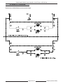
1
SERVICE MANUAL
ENDURANCE SERIES
GAS RANGES
MODELS
G36
G36C
G60
G60C
G260
G260C
G481
G481C
- NOTICE This manual is prepared for the use of trained Vulcan Service
Technicians and should not be used by those not properly
qualified. If you have attended a Vulcan Service School for this
product, you may be qualified to perform all the procedures
described in this manual.
This manual is not intended to be all encompassing. If you have
not attended a Vulcan Service School for this product, you should
read, in its entirety, the repair procedure you wish to perform to
determine if you have the necessary tools, instruments and skills
required to perform the procedure. Procedures for which you do
not have the necessary tools, instruments and skills should be
performed by a trained Vulcan Service Technician.
Reproduction or other use of this Manual, without the express
written consent of Vulcan, is prohibited.
For additional information on Vulcan-Hart or to locate an authorized parts and
service provider in your area, visit our website at www.vulcanhart.com
VULCAN-HART
DIVISION OF ITW FOOD EQUIPMENT GROUP, LLC
WWW.VULCANHART.COM
3600 NORTH POINT BLVD.
BALTIMORE, MD 21222
F35648 (May 2005)
ENDURANCE SERIES GAS RANGES
TABLE OF CONTENTS
GENERAL ............................................................................................................................................................... 3
Introduction ...................................................................................................................................................... 3
Installation ........................................................................................................................................................ 3
Operation ......................................................................................................................................................... 3
Cleaning .......................................................................................................................................................... 3
Lubrication ....................................................................................................................................................... 3
Specifications ................................................................................................................................................... 3
Tools ................................................................................................................................................................ 3
REMOVAL AND REPLACEMENT OF PARTS ......................................................................................................... 4
Covers and Panels ........................................................................................................................................... 4
Oven Manifold Cover (Models 60, 260, and 481) ...................................................................................... 4
Oven Control Panel (Model 36) ............................................................................................................... 4
Broiler Manifold Cover .............................................................................................................................. 5
Kick Panel Assembly ................................................................................................................................ 5
Standard Oven Control Valve/Thermocouple ................................................................................................... 6
Model 36 Only .......................................................................................................................................... 6
Model 60, 260, and 481 ............................................................................................................................ 7
Oven Pilot Assembly ........................................................................................................................................ 8
Oven Burner Assembly .................................................................................................................................... 8
Convection Oven Control Valve/Thermocouple Pilot ........................................................................................ 9
Oven Burner Nozzle and Orifice ..................................................................................................................... 10
Pilot Valve and Quick Disconnect Valve ......................................................................................................... 10
Top Section Burner Valve ............................................................................................................................... 11
Switch Replacement ...................................................................................................................................... 11
Motor Replacement ........................................................................................................................................ 11
Convection Oven Solenoid ............................................................................................................................. 12
SERVICE PROCEDURES AND ADJUSTMENTS ................................................................................................. 13
Pilot Flame Height .......................................................................................................................................... 13
Top Burners ............................................................................................................................................ 13
Broiler/Griddle......................................................................................................................................... 13
Air Shutter Adjustment ................................................................................................................................... 13
Oven Burner Adjustment ................................................................................................................................ 13
Regulator Check ............................................................................................................................................ 14
Regulator Adjustment ..................................................................................................................................... 14
Oven Burner Nozzle and Orifice Check .......................................................................................................... 15
Convection Oven Motor and Door Switch Check ........................................................................................... 15
Convection Oven Solenoid Check .................................................................................................................. 16
ELECTRICAL OPERATION ................................................................................................................................... 18
Component Function ...................................................................................................................................... 18
Sequence of Operation .................................................................................................................................. 18
Schematic Diagram........................................................................................................................................ 19
Wiring Diagrams ............................................................................................................................................ 20
Double Oven 120 Volt Endurance Convection Range (Drawing 1 of 2) .................................................. 20
Double Oven 120 Volt Endurance Convection Range (Drawing 2 of 2) .................................................. 21
TROUBLESHOOTING .......................................................................................................................................... 22
CONDENSED SPARE PARTS LIST ...................................................................................................................... 23
©VULCAN 2005
F35425 (October 2005)
Page 2 of 23
ENDURANCE SERIES GAS RANGES - GENERAL
GENERAL
INTRODUCTION
TOOLS
Procedures in this manual will apply to all models
unless specified. Pictures and illustrations can be of
any model unless the picture or illustration needs to
be model specific.
Standard
•
Standard set of hand tools.
•
VOM with A.C. current tester (Any quality VOM
with a sensitivity of at lease 20,000 ohms per
volt can be used).
•
Gear puller to remove blower.
INSTALLATION
Refer to the Installation and Operation Manual for
detailed installation instructions on ranges.
Special
OPERATION
•
Temperature tester (thermocouple type).
•
Manometer.
Refer to the Installation and Operation Manual for
specific operating instructions.
SPECIFICATIONS
Electrical (Convection ranges only)
CLEANING
Refer to the Installation and Operation Manual for
specific cleaning instructions.
LUBRICATION
•
Voltage - 120/60/1 or 240/60/1 (optional)
•
Amps - 15 Amps
•
Frequency - 50/60 Hz
Gas Line Pressures
The blower motor has sealed bearings and requires
no additional lubrication.
•
Natural - Recommended (in. W.C.) 7.0, min 5.0
•
Propane - Recommended (in. W.C.) 11.0, min 11.0
Maximum 14.0 in. W.C. (Nat. or Prop.)
Orifice Size Requirements for Different Elevations for Restaurant Range
OPEN TOP
GRIDDLE
BRO/GRID
(STD)
OVEN
(CON)
OVEN
32000/35000
15,000
10,000
35,000
35,000
ORIFICE SIZE
NAT/PROP
NAT/PROP
NAT/PROP
NAT/PROP
NAT/PROP
SEA LEVEL TO
2499 FT
36/51 (32000)
50/57
53/63
33/51
33/51
2499 FT TO
4499 FT
40/53 (32000)
37/52 (35000)
51/57
54/65
37/52
37/52
4500 FT TO
6499 FT
41/53 (32000)
38/52 (35000)
51/58
54/65
38/52
38/52
6500 FT TO
8499 FT
42/53 (32000)
40/53 (35000)
52/59
55/66
40/53
40/53
8500 FT TO
10,500 FT
42/54 (32000)
41/53 (35000)
52/60
55/67
41/53
41/53
INPUT AT SEA LEVEL
PER BURNER (BTU’S)
33/1.75MM
(35000)
Page 3 of 23
F35425 (October 2005)
ENDURANCE SERIES GAS RANGES - REMOVAL AND REPLACEMENT OF PARTS
REMOVAL AND REPLACEMENT OF PARTS
COVERS AND PANELS
3.
Remove screws holding manifold cover in place
and remove manifold cover.
4.
Reverse the procedure to install the oven
manifold cover.
WARNING: DISCONNECT THE
ELECTRICAL POWER TO THE
MACHINE AND FOLLOW LOCKOUT /
TAGOUT PROCEDURES.
Oven Manifold Cover (Models 60, 260, and 481)
1.
2.
Rotate the yellow gas shut-off valve to the OFF
position and allow range to cool.
Loosen the setscrew in the side of the burner
control knobs and oven control knob and remove
knobs.
F35425 (October 2005)
Oven Control Panel (Model 36)
1.
Rotate the yellow gas shut-off valve to the OFF
position and allow range to cool.
2.
Remove the red oven control valve knob from
the control valve.
3.
Open the kick plate at the bottom of the range.
Page 4 of 23
ENDURANCE SERIES GAS RANGES - REMOVAL AND REPLACEMENT OF PARTS
4.
Remove the screw securing the oven control
panel and remove the panel.
3.
Remove screws holding manifold cover in place
and remove broiler manifold cover.
4.
Reverse the procedure to install the broiler
manifold cover.
Kick Panel Assembly
5.
1.
Open kick panel.
2.
Remove two screws securing left hinge and
remove hinge.
3.
Slide kick plate to the left to disengage from left
hinge.
4.
Reverse the procedure to install the kick plate
assembly.
Reverse the procedure to install the oven control
panel.
Broiler Manifold Cover
1.
Rotate the yellow gas shut-off valve to the OFF
position and allow range to cool.
2.
Loosen the setscrew in the side of the burner
control knobs and remove knobs.
Page 5 of 23
F35425 (October 2005)
ENDURANCE SERIES GAS RANGES - REMOVAL AND REPLACEMENT OF PARTS
3.
Remove the two screws attaching the bracket to
the thermocouple.
Model 36
4.
Open the oven door.
The oven control valve is located to the front left of
the oven.
5.
Remove capillary tube from all routing clips.
STANDARD OVEN CONTROL
VALVE/THERMOCOUPLE
WARNING: DISCONNECT THE
ELECTRICAL POWER TO THE
MACHINE AND FOLLOW LOCKOUT /
TAGOUT PROCEDURES.
WARNING: SHUT OFF THE GAS BEFORE
SERVICING THE UNIT.
WARNING: ALL GAS JOINTS DISTURBED
DURING SERVICING MUST BE CHECKED FOR
LEAKS. CHECK WITH A SOAP AND WATER
SOLUTION (BUBBLES). DO NOT USE AN
OPEN FLAME.
1.
Remove the oven control panel as outlined
under PANELS AND COVERS.
2.
Remove the three bracket screws attaching the
thermocouple valve mounting bracket to the
range.
NOTE: When straightening the capillary tube be sure
not to place kinks in tubing.
F35425 (October 2005)
Page 6 of 23
6.
ENDURANCE SERIES GAS RANGES - REMOVAL AND REPLACEMENT OF PARTS
Slide the capillary tube out of the bracket and
Model 60, 260, and 481
straighten the tube so that it can be passed
The control valves are located behind the oven
through the hole in the oven sidewall.
manifold cover.
7.
Carefully slide the capillary tube through the
hole in the oven sidewall.
8.
Disconnect the gas input to the control valve.
9.
Disconnect the pilot tubing.
1.
Remove the oven manifold cover as outlined
under COVERS AND PANELS.
2.
Remove top burner grates and deflector,
if necessary, to access the control valve.
3.
Disconnect the pilot tubing from the control
valve.
4.
Remove two screws securing the control valve
to the manifold.
10. Disconnect the control valve burner tubing.
11. Remove the control valve assembly from the
oven.
12. Reverse the procedure to install a new control
valve assembly.
NOTE: During installation do not kink the new
capillary tube when feeding it through the hole in the
side of the oven cavity. Excess tubing can be loosely
wrapped.
Page 7 of 23
F35425 (October 2005)
ENDURANCE SERIES GAS RANGES - REMOVAL AND REPLACEMENT OF PARTS
5.
Remove the kick plate as outlined under
COVERS AND PANELS.
The oven pilot assembly is attached to the burner
assembly behind the kick plate.
NOTE: Do not kink the capillary tube when straightening the tubing for removal.
1.
Remove the kick plate as outlined under
COVERS AND PANELS.
6.
2.
Remove the oven rack.
3.
Remove the oven bottom.
4.
Remove the oven left and right liner.
5.
Remove the oven bottom heat shield.
6.
Remove the screws securing oven pilot
assembly to the burner assembly.
7.
Pull the pilot assembly out through the front of
oven.
8.
Reverse the procedure to install the oven pilot
assembly.
7.
Slide the capillary tube and thermocouple out of
the bracket and straighten the tube so that it can
be passed through the holes in the oven liner.
Remove the capillary tube from all routing clips.
8.
Carefully slide the capillary tube and
thermocouple through the holes in the oven.
9.
Remove the control valve, capillary tube, and
thermocouple from the unit.
10. Reverse the procedure to install a new control
valve assembly.
OVEN BURNER ASSEMBLY
NOTE: During installation do not kink the new
capillary tube when feeding it through the holes in the
oven. Excess tubing can be loosely wrapped.
WARNING: DISCONNECT THE
ELECTRICAL POWER TO THE
MACHINE AND FOLLOW LOCKOUT /
TAGOUT PROCEDURES.
OVEN PILOT ASSEMBLY
WARNING: DISCONNECT THE
ELECTRICAL POWER TO THE
MACHINE AND FOLLOW LOCKOUT /
TAGOUT PROCEDURES.
WARNING: SHUT OFF THE GAS BEFORE
SERVICING THE UNIT.
WARNING: ALL GAS JOINTS DISTURBED
DURING SERVICING MUST BE CHECKED FOR
LEAKS. CHECK WITH A SOAP AND WATER
SOLUTION (BUBBLES). DO NOT USE AN
OPEN FLAME.
F35425 (October 2005)
WARNING: SHUT OFF THE GAS BEFORE
SERVICING THE UNIT.
WARNING: ALL GAS JOINTS DISTURBED
DURING SERVICING MUST BE CHECKED FOR
LEAKS. CHECK WITH A SOAP AND WATER
SOLUTION (BUBBLES). DO NOT USE AN
OPEN FLAME.
The oven burner assembly is located behind the
kick plate.
1.
Page 8 of 23
Remove the oven pilot assembly as outlined
under OVEN PILOT ASSEMBLY.
ENDURANCE SERIES GAS RANGES - REMOVAL AND REPLACEMENT OF PARTS
2.
Remove the two screws securing the oven
burner assembly.
3.
Disconnect gas line to the burner.
4.
Pull the oven burner assembly out of the oven.
5.
Reverse the procedure to install a new oven
burner assembly.
5.
CONVECTION OVEN CONTROL
VALVE/THERMOCOUPLE PILOT
Remove the kick plate as outlined under
COVERS AND PANELS.
NOTE: Do not kink the capillary tube when straightening the tubing for removal.
6.
Slide the capillary tube and thermocouple out of
the bracket and straighten the tube so that it can
be passed through the holes in the oven liner.
7.
Remove the capillary tube from all routing clips.
WARNING: DISCONNECT THE
ELECTRICAL POWER TO THE
MACHINE AND FOLLOW LOCKOUT /
TAGOUT PROCEDURES.
WARNING: SHUT OFF THE GAS BEFORE
SERVICING THE UNIT.
WARNING: ALL GAS JOINTS DISTURBED
DURING SERVICING MUST BE CHECKED FOR
LEAKS. CHECK WITH A SOAP AND WATER
SOLUTION (BUBBLES). DO NOT USE AN
OPEN FLAME.
The control valve is located behind the oven manifold
cover.
1.
Remove the oven manifold cover as outlined
under COVERS AND PANELS.
8.
Carefully slide the capillary tube and
thermocouple through the holes in the oven.
2.
Remove top burner grates and deflector,
if necessary, to access the control valve.
9.
Remove the control valve, capillary tube and
thermocouple from the unit.
3.
Disconnect the pilot tubing.
4.
Remove the two screws securing the control
valve to the manifold.
10. Reverse the procedure to install a new control
valve assembly.
NOTE: During installation do not kink the new
capillary tube when feeding it through the holes in the
oven. Excess tubing can be loosely wrapped.
Page 9 of 23
F35425 (October 2005)
ENDURANCE SERIES GAS RANGES - REMOVAL AND REPLACEMENT OF PARTS
OVEN BURNER NOZZLE
AND ORIFICE
PILOT VALVE AND
QUICK DISCONNECT VALVE
WARNING: DISCONNECT THE
ELECTRICAL POWER TO THE
MACHINE AND FOLLOW LOCKOUT /
TAGOUT PROCEDURES.
WARNING: DISCONNECT THE
ELECTRICAL POWER TO THE
MACHINE AND FOLLOW LOCKOUT /
TAGOUT PROCEDURES.
WARNING: SHUT OFF THE GAS BEFORE
SERVICING THE UNIT.
WARNING: SHUT OFF THE GAS BEFORE
SERVICING THE UNIT.
WARNING: ALL GAS JOINTS DISTURBED
DURING SERVICING MUST BE CHECKED FOR
LEAKS. CHECK WITH A SOAP AND WATER
SOLUTION (BUBBLES). DO NOT USE AN
OPEN FLAME.
WARNING: ALL GAS JOINTS DISTURBED
DURING SERVICING MUST BE CHECKED FOR
LEAKS. CHECK WITH A SOAP AND WATER
SOLUTION (BUBBLES). DO NOT USE AN
OPEN FLAME.
The oven burner nozzle is mounted between the
oven gas supply tubing and the u-burner assembly.
The pilot valve for the griddle burners is mounted on
the gas supply manifold located behind the griddle
control panel.
1.
Turn off the burners.
2.
Disconnect the unit from gas flow and allow to
cool completely.
3.
Remove the kick plate as outlined under
COVERS AND PANELS.
4.
Remove the burner nozzle.
5.
Check for blockage or damage.
6.
Reverse the procedure to install the burner
nozzle.
F35425 (October 2005)
1.
Remove the oven manifold cover as outlined
under COVERS AND PANELS.
2.
Remove top burner grates and deflector, if
necessary, to access the pilot valve.
3.
Disconnect the pilot tubing from the holder.
4.
Disconnect the holder from the pilot valve.
5.
Remove the pilot valve from the manifold.
6.
Reverse the procedure to install a new pilot
valve.
Page 10 of 23
ENDURANCE SERIES GAS RANGES - REMOVAL AND REPLACEMENT OF PARTS
TOP SECTION BURNER
CONTROL VALVE
3.
Disconnect wiring from the switch.
4.
Remove the switch from mounting.
5.
Reverse the procedure to install the
replacement switch.
WARNING: DISCONNECT THE
ELECTRICAL POWER TO THE
MACHINE AND FOLLOW LOCKOUT /
TAGOUT PROCEDURES.
WARNING: SHUT OFF THE GAS BEFORE
SERVICING THE UNIT.
WARNING: ALL GAS JOINTS DISTURBED
DURING SERVICING MUST BE CHECKED FOR
LEAKS. CHECK WITH A SOAP AND WATER
SOLUTION (BUBBLES). DO NOT USE AN
OPEN FLAME.
MOTOR REPLACEMENT
1.
Remove the oven manifold cover as outlined
under COVERS AND PANELS.
2.
Allow the range to cool completely.
3.
Remove the burner grates and deflectors,
if necessary.
4.
Remove the griddle plate assembly, if necessary.
5.
Remove the burner mounting screws.
6.
Carefully move the burner assembly away from
the burner control valve.
NOTE: A centrifugal switch is mounted inside the
motor assembly. If electrical voltage is available to
the motor, the motor and switch must be replaced.
7.
Remove the burner control valve from the manifold.
1.
Remove cover from the motor junction box.
8.
Clean the manifold of any thread sealant.
9.
Inspect the control valve for wear and damage,
replace as necessary.
2.
Disconnect motor wiring at the junction box.
3.
If necessary, remove the motor guard.
WARNING: DISCONNECT THE
ELECTRICAL POWER TO THE
MACHINE AND FOLLOW LOCKOUT /
TAGOUT PROCEDURES.
10. Reverse the procedure to install a new burner
control valve.
NOTE: Apply a light coat of thread sealant to the
control valve threads before installing the burner
control valve in the manifold.
SWITCH REPLACEMENT
WARNING: DISCONNECT THE
ELECTRICAL POWER TO THE
MACHINE AND FOLLOW LOCKOUT /
TAGOUT PROCEDURES.
1.
Remove the oven manifold cover as outlined
under COVERS AND PANELS.
2.
Allow the range to cool completely.
Page 11 of 23
F35425 (October 2005)
ENDURANCE SERIES GAS RANGES - REMOVAL AND REPLACEMENT OF PARTS
4.
Inside the oven remove the hex head bolts and
spacers attaching the motor grate to the motor
mounting plate and remove the motor grate.
CONVECTION OVEN SOLENOID
WARNING: DISCONNECT THE
ELECTRICAL POWER TO THE
MACHINE AND FOLLOW LOCKOUT /
TAGOUT PROCEDURES.
WARNING: SHUT OFF THE GAS BEFORE
SERVICING THE UNIT.
WARNING: ALL GAS JOINTS DISTURBED
DURING SERVICING MUST BE CHECKED FOR
LEAKS. CHECK WITH A SOAP AND WATER
SOLUTION (BUBBLES). DO NOT USE AN
OPEN FLAME.
5.
Remove the motor and rotor blower assembly
from inside the oven.
6.
Remove the fan from the motor.
7.
Remove motor from motor mounting plate.
8.
Reverse the procedure to install a new motor.
F35425 (October 2005)
1.
Disconnect gas supply to the range.
2.
Disconnect the solenoid electrical connectors.
3.
Disconnect gas supply lines from both sides of
the solenoid.
4.
Remove solenoid mounting screws and
solenoid.
5.
Reverse the procedure to install the
replacement solenoid.
Page 12 of 23
ENDURANCE SERIES GAS RANGES - REMOVAL AND REPLACEMENT OF PARTS
SERVICE PROCEDURES AND ADJUSTMENTS
WARNING: CERTAIN PROCEDURES IN THIS SECTION REQUIRE ELECTRICAL TEST OR MEASUREMENTS WHILE POWER IS APPLIED TO THE MACHINE. EXERCISE EXTREME CAUTION AT ALL
TIMES. IF TEST POINTS ARE NOT EASILY ACCESSIBLE, DISCONNECT POWER AND FOLLOW
LOCKOUT / TAGOUT PROCEDURES, ATTACH TEST EQUIPMENT AND REAPPLY POWER TO TEST.
PILOT FLAME HEIGHT
Top Burners
To adjust the pilot flame height of the top burners,
locate the pilot adjustment screws found on the front
manifold pipe. It is not necessary to remove the
manifold cover as adjustment access holes have
been provided in the panel.
streaming flame on the burner is an indication of
insufficient air. To correct this condition, rotate the air
shutter open until the burner flame begins to lift from
the burner, then close the shutter slightly.
OVEN BURNER ADJUSTMENT
1.
Locate the pilot adjustment screw located
behind the adjustment access hole in the panel.
2.
Rotate the screw clockwise to decrease and
counterclockwise to increase the flame height.
All Endurance Range series units equipped with a
pressure regulator and fixed orifices have been
adjusted at the factory and should require no further
adjustments. However, the efficiency of the range
depends on a delicate balance between the air
supply and the volume of gas. Whenever this
balance is disturbed, poor operating characteristics
and excessive gas consumption will occur. An air
shutter on the front of the oven burner controls the
gas mixer balance.
Broiler/Griddle
To adjust pilot flame height of broiler/griddle, locate
the pilot adjustment screws found on the broiler/
griddle manifold pipe. It is not necessary to remove
the manifold cover, as adjustment access holes have
been provided in the panel.
1.
Locate the pilot adjustment screw located
behind the adjustment access hole in the panel.
2.
Rotate the screw clockwise to decrease and
counterclockwise to increase the flame height.
AIR SHUTTER ADJUSTMENT
The efficiency of the oven depends on a delicate
balance between the air supply and the volume of
gas. Whenever this balance is disturbed, poor
operating characteristics and excessive gas consumption will occur. An air shutter on the front of the
oven burner controls the gas mixer balance. A yellow
Page 13 of 23
F35425 (October 2005)
ENDURANCE SERIES GAS RANGES - SERVICE PROCEDURES AND ADJUSTMENTS
A yellow streaming flame on the burner is an indication of insufficient air. To correct this condition, open
the air shutter until the burner flame begins to lift
from the burner, then close the shutter slightly and
lock into place.
REGULATOR CHECK
A gas regulator is mounted between the gas service
outlet and the appliance.
5.
With regulator reading 7.0" W.C. (natural gas)
or 11.0" W.C. (propane gas), turn on two top
burners.
6.
Check regulator pressure reading. The reading
should be steady ± 0.10". If fluctuation in excess
of ±0.10" occurs replace the regulator.
NOTE: If pressure readings climb to limits shown in
step 4 with the burners OFF, check the leak (vent)
limit device for obstruction. Check the regulator for
leaks at the leak limiter vent. If vent is leaking,
replace the regulator.
REGULATOR ADJUSTMENT
NOTE: Before adjusting regulator, check incoming gas
line pressure. Incoming pressure must be 7.0" W.C.
for natural gas and 11.0" W.C. for propane gas. If
incoming pressure is not correct have the gas source
checked and adjusted as necessary. Make sure the
regulator is mounted in the horizontal position with the
arrow pointing in the direction of gas flow.
When servicing the equipment for possible gas
pressure problems, visually check that a regulator is
installed horizontal with the gas flow arrow pointing in
the direction of gas flow.
1.
Turn on the range top burners.
2.
Observe the burner flames.
1.
Connect manometer to the pressure tap
provided on the range gas piping between the
regulator and range.
2.
Check manometer reading. The reading should
be 7.0" W.C. for natural gas and 11.0" W.C. for
propane gas.
3.
If incoming line pressure is correct, adjust the
regulator. Remove the regulator closing nut.
4.
Insert a flat edge screwdriver through the
top of the regulator. Turn the adjusting screw
clockwise to increase pressure and
counterclockwise to decrease pressure.
5.
While watching the manometer, turn the
adjusting screw for proper regulator outlet
pressure.
6.
Install the regulator closing nut.
A leak (vent) limiting device is installed in each
regulator to limit gas leakage if the regulator ruptures.
Do not obstruct the leak limiter (vent). Obstruction may
cause regulator malfunction or failure.
3.
Connect the manometer to the pressure tap
provided between the regulator and range
supply piping.
4.
Turn on two top burners and note manometer
reading. The reading should be 7.0" W.C. for
natural gas units and 11.0" W.C. for propane
gas units. If readings are lower, check incoming
gas line pressure.
NOTE: The line pressure should never drop below
5.0" W.C. for natural gas or 11.0" W.C. for propane gas.
The incoming line pressure must be correct for
proper range operation. If line pressure is incorrect
have the gas supply source checked and adjusted.
If line pressure is correct adjust the regulator as
follows.
F35425 (October 2005)
Page 14 of 23
ENDURANCE SERIES GAS RANGES - SERVICE PROCEDURES AND ADJUSTMENTS
OVEN BURNER NOZZLE AND
ORIFICE CHECK
The oven burner nozzle is mounted between the
oven gas supply tubing and the u-burner assembly.
If burner operation seems poor and other systems
have been checked, remove the burner nozzle and
check for blockage or damage.
1.
Shut off the yellow gas supply knob.
2.
Allow the range to cool completely.
3.
Disconnect electrical power to the range.
4.
Loosen the screws in the sides of the control
valve knobs and remove the knobs.
5.
Remove the control panel mounting screws and
the control panel cover.
6.
Activate the power switch (see illustration)
several times and check for wear, damage, and
loose wiring connections. Repair connections as
necessary.
1.
Turn off burners and oven.
2.
Disconnect unit from gas flow and allow to cool
completely.
3.
Remove the kick plate as outlined under
COVERS AND PANELS.
7.
Connect electrical power to the range.
4.
Remove the burner nozzle.
8.
5.
Check for blockage or damage.
Check power connections for power range (220
volts AC or 120 volts AC).
9.
With the power switch in the ON position, check
for voltage at both switch connections. If no
voltage is available, check power source and
breakers. If voltage is available at switch input
only, replace the switch.
10. If voltage is available at power switch
connections, remove kick plate as outlined
under COVERS AND PANELS.
11. Locate the door switch.
12. Disconnect electrical power to the range.
NOTE: Nozzle blockage can be cleaned or nozzle
replaced. Use high-pressure water and tip cleaner to
clean the nozzle. Replace the nozzle if damaged or
blockage cannot be removed. Check nozzle for
correct orifice size and BTU rating. Use a flow meter
(available from Vulcan-Hart Service Parts Depots,
Part #495) to check BTU rate. See flow meter
instructions for proper installation and use.
13. Inspect the door switch for wear, damage, and
loose or broken connections. Repair as necessary.
14. Place multimeter in the continuity range. Check
for continuity between the switch connections in
the open and closed position. If continuity is not
available replace the switch.
15. If continuity is available with switch closed,
connect electrical power to the range.
16. Place multimeter in appropriate AC range (220
volts AC or 120 volts AC).
CONVECTION OVEN MOTOR
AND DOOR SWITCH CHECK
17. Place the power switch in the ON position.
A control switch mounted just below the convection
oven control valve controls the motor.
18. Check for voltage at the door switch input
connection. If voltage is not available,
disconnect electrical power and check continuity
between the motor switch and door switch.
Repair wiring as necessary.
19. If input voltage is available, carefully close the
switch (close the door) and check for voltage at
the switch output connection. If voltage is not
available, replace the switch.
20. If output voltage is available, disconnect
electrical power to the range.
21. Remove the cover from the motor electrical
junction box located on the back of the range.
Page 15 of 23
F35425 (October 2005)
ENDURANCE SERIES GAS RANGES - SERVICE PROCEDURES AND ADJUSTMENTS
22. With the motor switch and door switch in the
closed position, check for voltage at the motor
input connection. If voltage is available, replace
the motor. If voltage is not available, disconnect
electrical power from the range and check
continuity between the door switch output
connection and motor input connection.
Repair as necessary.
CONVECTION OVEN
SOLENOID CHECK
The convection oven solenoid is mounted between the
gas supply and convection oven burner assembly.
1.
Remove the kick plate as outlined under
COVERS AND PANELS.
2.
Locate the convection oven solenoid.
3.
Place the convection oven power switch in the
ON position. An audible click should occur when
the switch is activated. If the solenoid does not
cycle, check for proper voltage and ground at
the solenoid.
4.
Place the multimeter in the appropriate AC
range (220 volts AC or 120 volts AC). Check
for voltage at the solenoid. If voltage is not
available, check continuity between the power
switch and solenoid.
5.
If voltage is available, shut off electrical power
to the range. Place the multimeter in the
continuity range. Check for continuity between
the solenoid ground connection and a ground.
If continuity is not available, check and repair
ground connections.
6.
If continuity is available, remove the solenoid
and check for solenoid orifice obstruction. See
the procedure REMOVAL OF CONVECTION
OVEN SOLENOID for solenoid removal
instructions.
7.
Reinstall the solenoid.
F35425 (October 2005)
Page 16 of 23
- THIS PAGE INTENTIONALLY LEFT BLANK -
Page 17 of 23
F35425 (October 2005)
ENDURANCE SERIES GAS RANGES - SERVICE PROCEDURES AND ADJUSTMENTS
ELECTRICAL OPERATION
COMPONENT FUNCTION
Power Cord ..............................
Connects range to power source.
Solenoid Valve .........................
The solenoid is a normally closed valve. The solenoid opens when electrical
voltage flows to the solenoid coil. The coil is grounded on one side and
energized with voltage on the other side. When voltage flows a magnetic field
is created drawing on a spring-loaded plunger. When activated the plunger
opens allowing gas to flow to the burner assembly.
Door Switch .............................
Opens circuit to convection motor and solenoid when oven door is opened.
Single Phase
Convection Oven Motor ..........
Junction Box ............................
The convection oven motor circulates overheated air. The motor electrical
circuit is routed through door switches. The door closes the switch and allows
voltage to flow from the door switch to the motor. The motor should operate
with the door closed and shut off when the door is opened.
Connection point for electrical wires.
SEQUENCE OF OPERATION
Refer to schematic diagram.
Initial Conditions
1.
2.
3.
4.
Conditions.
A.
Power switch off.
B.
Oven door open.
Turn power switch on.
A.
Power applied to one side of convection oven motor and one side of solenoid.
B.
Power applied to common terminal on door switch.
Door switch closed.
A.
Power applied to other side of convection oven motor and motor operates.
B.
Power applied to other side of solenoid. Solenoid operates and opens gas flow to burner.
Door opened.
A.
Power removed from solenoid cutting off gas flow.
B.
Power is removed from convection oven motor causing motor to stop.
F35425 (October 2005)
Page 18 of 23
ENDURANCE SERIES GAS RANGES - ELECTRICAL OPERATION
SCHEMATIC DIAGRAM
Double Oven 120 Volt Endurance Convection Range
Page 19 of 23
F35425 (October 2005)
ENDURANCE SERIES GAS RANGES - ELECTRICAL OPERATION
WIRING DIAGRAMS
Double Oven 120 Volt Endurance Convection Range (Drawing 1 of 2)
F35425 (October 2005)
Page 20 of 23
ENDURANCE SERIES GAS RANGES - ELECTRICAL OPERATION
Double Oven 120 Volt Endurance Convection Range (Drawing 2 of 2)
Page 21 of 23
F35425 (October 2005)
ENDURANCE SERIES GAS RANGES - TROUBLESHOOTING
TROUBLESHOOTING
SYMPTOM
POSSIBLE CAUSES
Convection oven motor does not operate.
1.
2.
3.
Convection oven motor operates but no
gas flow to oven burner.
Faulty solenoid.
Convection oven motor noisy.
1.
2.
Pilots do not remain lit.
Low gas pressure. Check incoming gas line and check
regulator.
Burner flame too yellow.
1.
2.
F35425 (October 2005)
Oven door not closed.
Power switch not turned on.
Faulty convection motor.
Motor mounting loose.
Fan loose on motor shaft.
Check for correct orifice and for correct shutter adjustment.
Check for blockage at orifice.
Page 22 of 23
ENDURANCE SERIES GAS RANGES - CONDENSED SPARE PARTS LIST
CONDENSED SPARE PARTS LIST
ENDURANCE SERIES GAS RANGE
PART NO.
DESCRIPTION
411496-B1
Switch
411496-F1
Door Switch (Single Oven)
411496-F7
Door Switch (Double Oven)
497240-1
Griddle Valve
497246-1
Griddle Knob
404076
Burner Valve
428300-1
Burner Valve Knob
428904-1
Pilot Quick Disconnect Valve
404193-1
Broiler Pilot Valve
404193-2
Griddle Pilot Valve
497175-1
Solenoid Valve (36, 48 & RH of 60 & 260)
497175-2
Solenoid Valve (LH of 60 & 260)
412788-4
T/Couple (Single Oven)
428305-1
T/Couple (Double Oven)
419730-1
Motor
415780-2
Air Rotor
408279-26
Regulator 3/4 NPT (Single Oven) Nat. Gas
408279-27
Regulator 1 NPT (Single Oven) Nat. Gas
408279-21
Regulator 3/4 NPT (Single Oven) LP Gas
428807-1
Thermostat, Oven Control Valve (Single Oven)
428806-1
Thermostat, Oven Control Valve (Double Oven)
428617-1
Oven Thermostat Knob
Page 23 of 23
F35425 (October 2005)