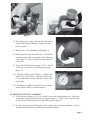
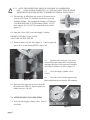
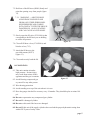
1
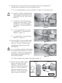
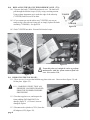
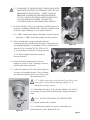
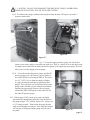
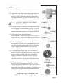
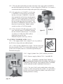
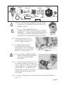
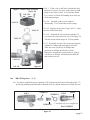
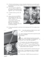
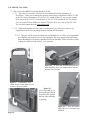
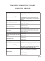
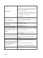
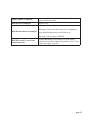
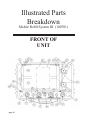
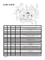
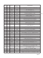
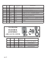
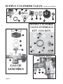
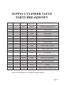
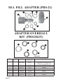
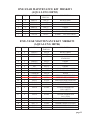
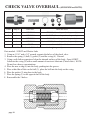
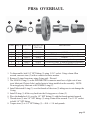
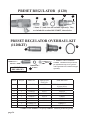
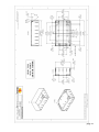
MRS III
Mobile Refill System
for the Aqua Lung SEA
(Survival Egress Air)
Operation and
Maintenance Manual
October, 2011
CHANGE RECORD
Change No.
Date
Title or Description
Change Made By
01-2010
5/2010
Add pages 35 & 36, Case dimensions, MRSIII
weights, empty & full
BAS
02-2010
5/2010
Page 26, items #7 & #11, part number changed
BAS
03-2010
9/2010
New page 34, 955SSMM check vakve overhaul
BAS
01-2011
9/2011
New page 35, PRS6 overhaul
BAS
02-2011
9/2011
New page 36, Preset Regulator and overhaul kit
moved to page 36.
BAS
03-2011
9/2011
Inline Bleeder Assembly moved to page 28
BAS
04-2011
9/2011
Page 28, items #69 & #70 added to list.
BAS
05-2011
10/2011
Page 35, item #347-1 added to picture and table
BAS
TABLE OF CONTENTS
SECTION 1................................................................................................................................................... 1
DESCRIPTION OF UNIT............................................................................................................... 1
SECTION 2................................................................................................................................................... 1
CONFIGURATION ......................................................................................................................... 1
FIGURE 1, MRS III UNIT ............................................................................................... 1
SECTION 3
............................................................................................................................................ 2
PREPARATION FOR USE ............................................................................................................. 2
FIGURE 2, CYLINDER HYDROSTAT STICKER .......................................................... 2
SECTION 4
............................................................................................................................................ 2
MRS III OPERATING INSTRUCTIONS........................................................................................ 2
SECTION 5
............................................................................................................................................ 2
OPERATION .................................................................................................................................. 2
OPENING VALVES ......................................................................................................................... 2
CONNECTING FILL HOSES ......................................................................................................... 2
FIGURE 3, OPENING SUPPLY CYLINDER VALVES .................................................. 2
LEAKING FITTINGS...................................................................................................................... 3
BLEEDER VALVES ........................................................................................................................ 3
FIGURE 4, CONNECTING SEA FILL HOSES ............................................................... 3
FIGURE 5, CLOSE BLEEDER VALVE ........................................................................... 3
FIGURE 6. OPEN PANEL-MOUNTED VALVES ........................................................... 3
FIGURE 7, FILL PRESSURE GAUGE ............................................................................ 3
SECTION 6
............................................................................................................................................ 3
REFILLING SUPPLY CYLINDERS ............................................................................................... 3
CHECK HYDROSTAT DATE ......................................................................................................... 3
VISUAL INSPECTION ................................................................................................................... 3
FILL ADAPTERS ............................................................................................................................ 3
FIGURE 8, FILL ADAPTER ............................................................................................. 4
FIGURE 9, REMOVE RUBBER CAP ............................................................................ 4
FIGURE 10, CONNECT TO AIR INLET FITTING......................................................... 4
FIGURE 11, CHECK SUPPLY AIR PRESSURE ............................................................. 4
SECTION 7
............................................................................................................................................ 4
AFTER FILLING IS COMPLETED ............................................................................................... 4
FIGURE 12, DRAINING FILL HOSE ............................................................................. 5
FIGURE 13, PUTTING AWAY FILL HOSE .................................................................... 5
SECTION 8
............................................................................................................................................ 5
WARNINGS ..................................................................................................................................... 5
MRS III MAINTENANCE
SECTION 9
............................................................................................................................................ 6
AFTER ONE YEAR, AND EVERY YEAR THEREAFTER .......................................................... 6
OVERHAUL SEA ADAPTERS...................................................................................................... 6
FIGURE 14, REPLACE FILL ADAPTER ASSEMBLY ................................................. 6
FIGURE 15, PRS21-8 ...................................................................................................... 6
INSTALLING SEALS ..................................................................................................................... 7
FIGURE 16, USING PRS21-8-1 ...................................................................................... 7
FIGURE 17, USING PRS21-8-2 ....................................................................................... 7
FIGURE 18, USING PRS21-8-3 ...................................................................................... 7
FIGURE 19, FINISHED SPINDLE AND BODY ............................................................ 7
SECTION 10 ............................................................................................................................................ 8
REPLACING BLEEDER VALVE SEAT......................................................................................... 8
FIGURE 20, BLEEDER VALVE AND SEAT ................................................................... 8
SECTION 11 ............................................................................................................................................ 8
DISASSEMBLING UNIT................................................................................................................ 8
REMOVING TOP PLATE ............................................................................................................... 8
FIGURE 21, REMOVE SCREWS FROM PLATE ........................................................... 8
I
FIGURE 22, REMOVE TOP PLATE ................................................................................ 8
FIGURE 23, INSPECT FOAM PADDING ....................................................................... 8
FIGURE 24, DISCONNECT CYLINDERS...................................................................... 9
REMOVING CYLINDERS ............................................................................................................. 9
FIGURE 25, REMOVE CYLINDERS ............................................................................. 9
CGA INSPECTION REQUIREMENTS .......................................................................................... 9
REINSTALL SUPPLY CYLINDER ................................................................................................ 9
FIGURE 26, CONNECTING O’ RING............................................................................ 9
SECTION 12 .......................................................................................................................................... 10
CYLINDER INSPECTION GUIDELINES ................................................................................... 10
SECTION 13 .......................................................................................................................................... 10
REMOVING UNIT FROM CASE................................................................................................. 10
FIGURE 27, REMOVE SCREWS FROM BACK .......................................................... 11
FIGURE 28, REMOVE UNIT FROM CASE ................................................................. 11
SECTION 14 .......................................................................................................................................... 10
GAUGE CALIBRATION .............................................................................................................. 11
REMOVING GAUGES ................................................................................................................. 11
FIGURE 29, REMOVE AND REPLACE GAUGE ....................................................... 11
REINSTALLING GAUGE............................................................................................................. 12
REINSTALLING UNIT ................................................................................................................. 12
PRESSURE TEST .......................................................................................................................... 12
SECTION 15 .......................................................................................................................................... 12
AFTER FIVE YEARS AND EVERY FIVE YEARS THEREAFTER .......................................... 12
HYDROSTAT OF CYLINDERS ................................................................................................... 12
FILL VALVE MAINTENANCE .................................................................................................... 13
FIGURE 30, FILL VALVE ASSEMBLY ......................................................................... 13
SUPPLY CYLINDER VALVES ..................................................................................................... 14
FIGURE 31, SUPPLY CYLINDER VALVE ................................................................... 14
REMOVING SUPPLY CYLINDER VALVE ................................................................................ 14
FIGURE 32, VAL1-10 TOOL .......................................................................................... 14
FIGURE 33, USING VAL1-10 ........................................................................................ 14
FIGURE 34, SUPPLY CYLINDER VALVE ASSEMBLY............................................ 15
FIGURE 35, VAL1-12 VALVE NUT TOOL ................................................................... 15
FIGURE 36, REMOVE BONNET W/VAL1-12 ............................................................. 15
FIGURE 37, REMOVE BONNET W/ WRENCH .......................................................... 15
REPLACING SAFETY DISC........................................................................................................ 16
FIGURE 38, SAFETY DISC PLACEMENT .................................................................. 16
SUPPLY VALVE GAUGE MAINTENANCE .............................................................................. 16
FIGURE 39, VAL1-11 GAUGE TOOL ........................................................................... 16
FIGURE 40, REMOVE GAUGE W/VAL1-11 ................................................................ 16
FIGURE 41, SUPPLY CYLINDER GAUGE ASSEMBLY ............................................ 17
SECTION 16 .......................................................................................................................................... 17
MRS III REGULATOR .................................................................................................................. 17
REMOVING FROM MRS III ........................................................................................................ 17
FIGURE 42, REGULATOR ASSEMBLY ....................................................................... 17
FIGURE 43, REGULATOR FITTINGS .......................................................................... 18
FIGURE 44, ACORN NUT ............................................................................................. 18
FIGURE 45, 1120KIT-1 DETAIL .................................................................................... 19
REASSEMBLE REGULATOR ..................................................................................................... 19
PRESSURE TESTING ................................................................................................................... 19
SECTION 17 .......................................................................................................................................... 19
MRS III CASE ............................................................................................................................... 19
CASE WARRANTY INSTRUCTIONS......................................................................................... 20
FIGURE 46, CASE LATCHES........................................................................................ 20
FIGURE 47, HANDLE LATCH ...................................................................................... 20
FIGURE 48, CARRY HANDLES ................................................................................... 20
FIGURE 49, HANDLE AND WHEELS ......................................................................... 20
II
TROUBLE SHOOTING CHART ........................................................................................................21-23
ILLUSTRATED PARTS BREAKDOWN ................................................................................................ 24
MRS III UNIT COMPLETE ASSEMBLY................................................................................26-28
INLINE BLEEDER ASSEMBLY .................................................................................................. 28
FILL VALVE .................................................................................................................................. 29
SUPPLY CYLINDER VALVE ..................................................................................................30-31
SEA FILL ADAPTER .................................................................................................................... 32
ONE-YEAR MAINTENANCE KIT .............................................................................................. 33
FIVE-YEAR MAINTENANCE KIT ............................................................................................. 33
955SSMM CHECK VALVE .......................................................................................................... 34
PRS6..... .......................................................................................................................................... 35
REGULATOR ................................................................................................................................ 36
MRS III FLOW DIAGRAM ......................................................................................................................... 37
PELICAN CASE, DIMENSIONS, TOP ...................................................................................................... 38
PELICAN CASE, DIMENSIONS, BOTTOM ............................................................................................. 39
WARNING:
This unit contains air under high pressure. Serious injury may result from misuse of this
apparatus and the gas it contains.
Avoid blowing compressed gas at yourself or any other person.
Wear hearing protection.
Avoid standing over top of the unit when it is in use.
Have the gauges checked for accuracy every 18 months. They should be plus or minus
100psi.
Do not overpressurize any compressed gas cylinder.
Do not fill a damaged cylinder.
Do not use this unit if the hoses are damaged.
Do not fill this unit if the supply cylinders have not had the proper hydrostatic testing done
within five years of today’s date.
WARNINGS, CAUTIONS, & NOTES
Pay special attention to information provided in warnings, cautions, and notes that are accompanied
by one of these symbols:
A WARNING indicates a procedure or situation that may result in serious injury or death if
instructions are not followed correctly.
A CAUTION indicates any situation or technique that will result in potential damage to the
product, or render the product unsafe, if instructions are not followed correctly.
A NOTE is used to emphasize important points, tips, and reminders
III
MRS III
Mobile Refill System
1.0 DESCRIPTION OF UNIT: The MRS III is designed to refill the Aqua Lung Survival Egress
Air (SEA) LV, MK1.5, MK2, MK2.5. It has an internal supply of two carbon fiber composite
4500psi cylinders and has two preset regulated 3000psi fill lines. The control panel will allow
you to monitor the pressure in the supply cylinders, verify the preset regulated pressure and control the filling of one or two SEA units.
2.0 CONFIGURATION: The attached picture shows the COMPLETE MRS III UNIT. The items
lettered are listed below.
M
D
A
N
F
R
F
B
G
P
H
I
J
O
K
M
Q
L
O
A
E
Q
C
figure 1
A.
B.
C.
D.
E.
F.
G.
H.
I.
Supply Cylinder (CYL1)
Refill Port w/ rubber cap (RCAP)
Adapter PRS6 to CGA 347
Case (1650)
Frame/Control Panel (FRM1)
SEA fill adapter (PRS21)
Bleeder valves (712)
Fill Hose (HOS1)
SEA Fill pressure Gauge (GAG1)
MRS III
J. Supply Pressure Gauge (GAG1)
K. Preset regulator (1120)
L. Regulated Pressure Gauge (GAG1)
M. Fastener for top cover of the frame
N. Top Cover/ Instruction sheet
O. Fill Valves (YVA3010A)
P. Supply Cylinder Valves (VAL1)
Q. SEA Cylinder Holder/Burst Protector
R. Unit/serial number, Manufacture date
NOTE: These identification letters do not match the I.D. numbers in the PARTS section, page 25
page 1
3.0 PREPARATION FOR USE: First unpack the unit and check for damage caused by shipping.
Next, open the case.. Verify the hydrostatic test date of the supply cylinders, shown on a sticker
prominently displayed on the cylinder (figure 2) and on the neck of supply cylinders (figure 3).
This should also be written on the maintenance log, located on the lower right hand corner of the
instruction sheet.
3.1 NOTE: THESE CYLINDERS (CYL1)
REQUIRE HYDROSTATIC TESTING
EVERY 5 YEARS, BY A DOTAPPROVED TEST FACILITY. CHECK
DATE STICKER ON CYLINDER (figure 2),
OR ON CYLINDER NECK. (figure 3)
3.2. Since the unit is shipped from the factory empty
you must fill it with air (see Refilling Supply
Cylinders, Section 6). The MRS III is now ready
to fill SEA cylinders.
figure 2
4.0 MRS III OPERATING INSTRUCTIONS
4.1. The purpose of this unit is to allow the filling either MK or LV series SEA cylinders to
3000psi from an internal source of approved breathing air. You can fill either one or two at
a time.
4.1.1. WARNING-DO NOT FILL CYLINDERS THAT ARE DAMAGED OR THAT
HAVE LIQUID IN THEM. THEY MUST BE INSPECTED ACCORDING TO
MANUFACTURERS INSTRUCTIONS
5.0 OPERATION:
5.1. Make sure the fill valves (YVA3010A) on the panel are
closed.
5.2. Open the valves (VAL1) on the supply cylinders
(figure 3). Valves lock in place when released. To release,
push the knob while turning. Verify that the pressure in the
supply cylinders is between 3000 and 4500psi .
5.3. Verify that the Regulated Pressure Gauge on the panel
shows 3000psi, +/- 100 psi. If it does not, have a technician that has been trained on the maintenance of the MRS III
adjust the regulator, per 16.11.
O
DR
Y
H TE
DA ER
CK
STI
figure 3
5.4. Place the SEA in the cylinder holder.
5.5. Connect the SEA to the fill hose, by placing the fill
adapter (PRS21) into the fill port and rotating the knob
clockwise until the O-ring is fully seated. (figure 4)
5.5.1. CAUTION-DO NOT USE A WRENCH OR PLIERS TO TIGHTEN!!!
page 2
figure 4
figure 5
5.6. If the fitting leaks, remove from the SEA and inspect
threads and O-ring for damage. Replace or repair
parts as needed.
5.7. Bleeder valve (712) should be closed (figure 5).
5.8. Slowly open the panel mounted valve (YVA3010A),
counterclockwise, that corresponds to the fill hose(s)
used (figure 6). There is no need to open any valve
on the SEA.
5.9. Watch the SEA fill pressure gauge (CAG1). Fill the
cylinder at a rate not to exceed 500psi per minute
(figure 7).
figure 6
5.10. After the cylinder reachs 3000psi +/- 100psi, close
the fill valve (YVA3010A). Open the bleeder valve
(712) on the fill hose used to vent the pressure from
the fill lines.
5.11. Disconnect the fill hose from the SEA, by rotating
the fill adapter (PRS21) counterclockwise.
figure 7
6.0 REFILLING SUPPLY CYLINDERS:
6.1. Verify that the cylinders (CYL1) are within 5 years of the last hydrostatic test. Check the
dated sticker placed prominently on each cylinder (figure 2). There is also a sticker on the
cylinder neck, visible without removing MRS top plate (figure 3).
6.2. Visually check the observable portion of the outside of the cylinders for damage. If any is
found consult manual for acceptable/unacceptable conditions.
page 3
6.2.1. NOTE-THIS INSPECTION SHOULD CONFORM TO COMPRESSED
GAS
ASSOCIATION PAMPHLET C-6.2 VISUAL INSPECTION OF FIBER
REINFORCED HIGH PRESSURE CYLINDERS (EXTERNAL INSPECTION ).
6.3. This unit may be filled from any source of air that meets or
exceeds CGA Grade “D” standards at pressures up to and
including 4500psi. The standard inlet fitting is a 4500psi or
a 300 BAR DIN (DIN-F) SCUBA fitting (PRS6). For US
users, adapter for CGA 347 fill connections are provided.
(figure 8)
figure 8
6.4. Open the valves (VAL1) on both Supply Cylinders.
REFER TO FIGURE 3 (page 2) FOR
A PICTURE OF THE VALVES
6.5. Remove rubber cap. (RCAP). (figure 9) Connect approved
source of air to inlet fitting (DIN-F) (figure 10).
figure 9
6.6.
Pressurize the system at a rate not to
exceed 500psi per minute until it reaches the
maximum pressure of the approved air supply,
or 4500 psi, whichever is lower. (figure 11).
6.7.
Close the supply cylinder valves
(VAL1).
figure 10
6.8.
Close the valve from the approved air
source and bleed the air from the fill connector.
6.9. Disconnect the approved air source from the
fill connection (DIN-F). Replace protective
rubber dust cap. (RCAP)
7.0 AFTER FILLING IS COMPLETED:
7.1. Verify that the supply cylinder valves (VAL1)
are closed.
figure 11
page 4
7.2. Hold one of the fill hoses (HOS1) firmly and
point the opening away from people (figure
12).
7.2.1. WARNING — AIM THE HOSE
AWAY FROM YOURSELF AND
FROM ANY OTHER PERSONNEL.
HIGH PRESSURE AIR COMING
INTO CONTACT WITH THE SKIN IS
DANGEROUS. ALSO, ESCAPING
AIR CAN CAUSE A LOUD NOISE.
7.3. Slowly open the fill valve (YVA3010A) that
corresponds to the fill hose you are holding
to release all pressure.
figure 12
7.4. Close all fill hose valves (YVA3010A) and
bleeder valves (712).
7.5. Attach the fill hoses to the
provided mounts (NUT2)
(figure 13).
7.6. Close and securely latch the lid.
8.0 WARNINGS:
8.1. This unit contains air under
high pressure. Serious injury
may result from misuse of this
apparatus and the gas it contains.
8.2. Avoid blowing compressed gas
at yourself or any other person.
figure 13
8.3. Wear hearing protection.
8.4. Avoid standing over top of the unit when it is in use.
8.5. Have the gauges checked for accuracy every 18 months. They should be plus or minus 100
psi.
8.6. Do not overpressurize any compressed gas cylinder.
8.7. Do not fill a damaged cylinder.
8.8. Do not use this unit if the hoses are damaged.
8.9. Do not fill this unit if the supply cylinders have not had the proper hydrostatic testing done
within FIVE years of today’s date.
page 5
MRS III MAINTENANCE
Scheduled Service (1-year and 5-year)
9.0 AFTER 1 YEAR, AND EVERY YEAR THEREAFTER....
9.1. PARTS REQUIRED: 1-year overhaul kit ( Part Number MRSKIT1).
9.2. Open the Supply Cylinder valves (VAL1) and then slowly vent all air from the MRS III thru
one of the fill hoses (HOS1).
9.2.1. WARNING — AIM THE HOSES AWAY FROM YOURSELF AND FROM ANY
OTHER PERSONNEL. HIGH PRESSURE AIR COMING INTO CONTACT WITH
THE SKIN IS DANGEROUS. ALSO, ESCAPING AIR CAN CAUSE A LOUD NOISE.
9.3. Replace all seals in the SEA fill adapter (PRS21). See figure 14. This consists of three
O-rings, two (PRS21-3) and one (PRS21-6), and two back-up rings (PRS21-2).
9.3.1. The first O-ring (PRS21-6) is the one that makes the seal to the SEA. This is a normal
wear item and can be replaced anytime. The tools required are an O-ring pick and the
PRS21-8-3 (figure 15).
PRS21-3 PRS21-5 PRS21-4
PRS21-2
PRS21-6
PRS21-1
PRS21-3
PRS21-2
figure 14
9.4. To replace the other parts will require
a set of external snap-ring pliers, an O-ring
pick, the PRS21-8 , and some non-toxic O-ring
lubricant (Christo-lube).
9.5. To start, remove the visible O-ring
(PRS21-6). Then using the snap-ring pliers
remove the snap-ring (PRS21-5) and set it aside.
Grasp the hex knob (PRS21-1) in one hand and
hold the body (PRS21-4) in the other. Pull apart
with a slight rotating motion of the hex knob.
Use the O-ring pick to remove the O-rings and
back-up rings.
9.5.1. NOTE THE ORDER THAT THE PARTS
ARE ON THE SHAFT: STARTING
FROM THE HEX KNOB — BACK-UP
RING (PRS21-2); O-RING (PRS21-3);
O-RING(PRS21-3); BACK-UP RING
(PRS21-2); SNAP-RING (PRS21-5);
O-RING (PRS21-6). See figure 14.
PRS21-8-2
9.6. Clean the parts with a soft clean cloth to remove
all of the old lubricant. Inspect parts for
damage. If any is found replace the assembly.
PRS21-8-1
page 6
PRS21-8-3
figure 15
NOTE: PRS21-8 (103384) comes as a
complete set; not available separately.
9.7. Lubricate the new seals generously with an approved non-toxic O-ring lubricant
(Christo-lube), and slip the new seal on in the proper order.
9.7.1 It is recommended that you use tool set PRS21-8 (figure 15) to install the seals.
9.7.1.1 NOTE; INSTALL THE BACKUP
RINGS (PRS21-2) WITH THE CONCAVE SIDE FACING THE O-RINGS
(PRS21-3).
PRS21-2
9.7.1.2 Install the seals and backup rings
starting from the hex knob. If using
the PRS21-8-1, first install backup
ring (PRS21-2) and O-ring (PRS21-3)
(figure 16).
PRS21-3
figure 16
PRS21-2
9.7.1.3 Next, using PRS21-8-2, install
O-ring (PRS21-3) and backup ring
(PRS21-2) (figure 17).
9.7.1.4 Using PRS21-8-3, install O-ring
(PRS21-6) (figure 18).
PRS21-3
9.8 If tool set PRS21-8 is not available, install
the seals with an O-ring pick, in the same
order as 9.7.2, above. Carefully avoid
stretching and nicking the seals while
installing them.
figure 17
PRS21-6
9.8.1. CAUTION: INSTALL THE SEALS
OVER THE THREADED END. DO NOT
ATTEMPT TO STRETCH THEM OVER
THE KNOB, AS DAMAGE TO THE
SEALS WILL RESULT.
figure 18
9.8.2 When completed, the spindle will look like in figure 19.
9.9. Once the seals are in place, lightly
lubricate the inside of the body
(PRS21-4) with Christo-lube,
and slide the spindle into the body
(figure 19). Once the spindle is
in the body install the snap-ring
(PRS21-5), using snap ring pliers.
Wipe off any excess lubricant.
PRS21-4
PRS21-5
PRS21-1
figure 19
page 7
10.0 REPLACING THE SEAT IN THE BLEEDER VALVE (712):
10.1. Unscrew the knob (712KNOB) and turn it over. The knob will
pull through the bleeder keeper (59) by using a twisting motion.
Using a sharp instrument get it under the edge of the white tip
(712SSTIP) and lift it out of its hole.
712SSTIP
10.2. If you cannot get out the white seat (712SSTIP) you may attempt to dig it out with an O-ring pick or simply replace the knob
assembly (712KNOB). See figure 20.
712KNOB
figure 20
10.3. Push 712SSTIP into hole. Reinstall in bleeder keeper.
figure 22
From this point on, it might be easier to perform
maintenance with the system removed from the
case. See section 13.0.
figure 21
11.0 REMOVING THE TOP PLATE:
11.1. There are six (6) screws that hold the top plate to the unit. Unscrew these (figure 21) and
lift the plate (figure 22).
11.1.1. WARNING-VERIFY THAT ALL
PRESSURE HAS BEEN DRAINED
FROM THE PLUMBING BEFORE
PROCEEDING.
11.2. Turn the top plate over, and inspect the
foam padding (PAD1and PAD2) for
damage (figure 23 ). If foam is worn or
damaged, replace.
11.3. Disconnect the cylinders (CYL1) from the
fill adapters (835) (figure 24).
page 8
PAD2
PAD1
figure 23
11.3.1. WARNING: IF THESE DO NOT COME LOOSE WITH
FIRM HAND STRENGTH, THERE MAY STILL BE AIR
PRESSURE IN THE SYSTEM. VERIFY THAT ALL
PRESSURE IS REMOVED BEFORE PROCEEDING.
IF YOU CANNOT GET THIS LOOSE BY HAND YOU
CAN USE SLIP JOINT PLIERS. DO NOT USE
EXCESSIVE FORCE AS DAMAGE WILL RESULT.
11.4. Lift the cylinders (CYL1) out of the frame (FRM1) (figure 25).
Inspect the padding (TRIM & PRS17) that the cylinders rest on.
If it shows signs of damage or wear, replace with new.
11.4.1 PRS17 replacement requires altering by cutting it into two
equal pieces. PRS17 makes the padding for both cylinders.
11.5. Have an authorized / properly trained technician
visually inspect the cylinder inside and out to Compressed Gas
Association Pamphlet C-6.2 standards (This is available direct
from the CGA by calling 703-788-2700 ext.799
or via email from [email protected])
figure 24
11.5.1 Basic cylinder inspection criteria are
listed in section 12.
11.6. Inspect all other components for obvious
damage or excessive wear. If damage or wear is
found, replace that component.
11.7. After the cylinders (CYL1) have been inspected
it is time to reassemble the unit. Place a cylinder
into the frame and line up the valve (VAL1) with
the connection (835).
figure 25
11.7.1. Before connecting, verify that the O-ring (010) in the
connection is in place and not damaged (figure 26). If
damaged or missing, replace.
11.8. Thread the fill adapter (835) onto the cylinder valve (VAL1)
by turning it clockwise until it pulls up tight. Snug this firmly by
hand.
11.8.1. DO NOT USE TOOLS TO TIGHTEN THIS.
O-ring (010)
11.9. Repeat with the other cylinder.
11.9.1. When both cylinders are in place, reinstall the top
plate/instruction sheet. Reinstall in case.
figure 26
page 9
12.0
CYLINDER INSPECTION GUIDELINES
12.1 Cuts, Scuffs and Scratches
12.1.1 Usually these are confined to clear coat and are less than .005” deep. Flaws in clear
coat alone are acceptable and repairable.
12.1.2 Flaws in clear coat can be repaired with any 5 minute epoxy, and then hydrostatically
tested by a trained and authorized test facility before returning to service.
12.1.3 Rejectable flaws have visible fiber damage. If damage extends into the fibers replace
the cylinder and destroy the damaged cylinder.
12.1.4 Heat or fire damage that causes discoloration or charring is cause for
rejecting the cylinder.
12.2 Delamination
12.2.1 Delamination calls for rejecting the cylinder.
12.3 Impact
12.3.1 Look for fiber delamination; if delaminated, reject cylinder.
12.3.2 Transverse fiber breaks call for rejecting the cylinder.
12.3.3 Small impacts will show white spots without significant delamination. If no fiber
breakage is noted and damage is less than 1/2” diameter and there is no dent, cylinder
may be hydrostatically tested and returned to service.
12.4 Internal inspection (to be performed by trained and authorized inspection center only)
12.4.1. Check for cracks in the neck area. If cracks are present reject the cylinder.
12.4.2. Check cylinder walls for corrosion. If corrosion is present have an authorized test
facility remove the corrosion and check for cylinder wall pitting damage.
12.4.2.1. If pitting exceeds the allowable limits reject the cylinder. Limits are not
printed here as a properly trained inspector will have this data available
and it is subject to change .
If there is any question as to the integrity of the cylinder either replace it or return it to
Breathing Air Systems (614-864-1235 or [email protected]) for evaluation.
13.0
WHER FURTHER MAINTENANCE IS SCHEDULED OR REQUIRED, REMOVE
THE UNIT FROM THE CASE.
13.1. With the lid closed and latched, turn the MRS III over. Remove the four screws from the back
of the case. (figure 27).
13.2. Turn case over, open lid, and lift the unit out of the case (figure 28).
13.2.1 Be sure to support the plumbing with your hand as you lift the frame.
14.0 GAUGE CALIBRATION: The gauges (GAG1) on this unit are of a sealed design. You have to
verify the accuracy. Gauge calibration in accordance with local instructions. Acceptable variance is
100psi in the center of the range (1500psi to 4500psi), or ±200psi at the bottom or top of range. If not
within these limits they will have to be replaced.
14.1. To verify the calibration on these gauges (GAG1), they may be removed from the system, or
they can be checked in the system if the calibration technician has the proper connectors.
page 10
14.1.1. CAUTION: DO NOT CONTAMINATE THE MRS III BY USING CALIBRATION
APPARATUS THAT WILL PUT OIL INTO THE SYSTEM.
14.1.2 To calibrate the gauges without removing them from the unit will require you make 3
separate connections.
figure 28
figure 27
14.1.3 To test the supply pressure gauge you will need to
connect your master gauge to the refill port with a tee. There is a check valve on this port so the
air supply must come from the refill port and test gauge to the supply pressure gauge. This will
allow you to test the supply pressure gauge.
14.1.4 To test the regulated pressure gauges and the fill
pressure gauges you can connect your test gauge to
one of the fill lines (removing the PRS-21 for access
to a 1/4” NPT). Use air from the supply cylinders
or supply air thru the refill port to pressurize these
gauges. This will allow you to check the fill pressure
gauge on the side that you are connected on and the
regulated pressure gauge. Remove the test gauge;
reinstall the PRS21 and repeat on the other side for
the other fill pressure gauge.
14.2. If the gauges (GAG1) need to be removed simply
disconnect the tubing fitting (PRS10) from the back of
the gauge using a 7/16” wrench (figure 29). Always use
a 3/4” backup wrench. Then loosen the gauge bracket
with a small straight screwdriver. Once loose the bracket
will slip out of the gauge and the gauge will lift out of
the panel.
figure 29
page 11
14.3. The rear connection on the gauge is ¼” MNPT and will have a standard industrial 1/8” tube highpressure compression fitting (PRS10). The calibration technician may connect either to the
compression fitting or to the ¼” MNPT.
14.4. If the compression fitting is removed it must be reinstalled with PTFE (Teflon) tape. Reinstall the
gauge by reversing the removal procedure. The compression fitting should be tightened by hand
and then snugged firmly with a 7/16” wrench (see figure 29).
14.5. When the inspection and gauge calibration is done, reinstall the frame (FRM1) into the case
(1650). This is easily done by placing the case on a table and lifting the frame into the case.
Close the lid, and turn unit over. Insert the four screws (BLT3), and tighten.
14.5.1 If you have trouble aligning the screw holes, turn the unit right-side up and open the lid.
Then slide the case partway off of the table and reach under the case and start two of the screws
(BLT3). Run these in snug but not tight. Turn the case around so that you can start the other
two screws.
14.6. Once all 4 screws are started, tighten all of them securely by hand with #3 Phillips screwdriver.
14.7. Install cylinder per reverse of 11.7 through 11.9.1. Reinstall top plate per reverse of 11.1.
14.8. The MRS III is now ready to pressure test. Close the supply cylinder valves (VAL1). Attach the
approved source of CGA grade “D” Breathing Air to the refill port (DIN-F) and slowly pressurize to
1000psi. Close the valve on the refill source. Allow the unit to stand for 5 minutes. After 5
minutes check for pressure loss. If there was pressure loss repair the leaks and start again.
14.9. If there was no pressure loss, you may pressurize to 4500psi (or to the limit of your supply,
whichever is lower). Once the plumbing is at full pressure, hold it there for 5 minutes and check
for pressure loss. When the pressure will hold for 5 minutes with no leaks it is time to recharge the
supply cylinders, following the procedure from section 6. Return the unit to service.
15.0 AFTER 5 YEARS OF SERVICE AND EVERY 5 YEARS THEREAFTER....
15.1. Perform all of the 1-year maintenance. While unit is removed from case, proceeed with 5-year
maintenance.
15.2. While the cylinders are out of the unit they must to be hydrostatically tested according to the DOT
standard. This is done by sending them out to an authorized DOT testing facility, or by returning
them to Breathing Air Systems (contact Breathing Air Systems at 800-937-2479 or 614-864-1235,
or via e-mail at [email protected] ).
15.2.1. NOTE: AS OF OCTOBER 2000 THE CARBON FIBER WRAPPED CYLINDERS (CYL1)
USED IN THE MRS III HAVE A MAXIMUM SERVICE LIFE OF 15 YEARS.
15.2.2. Cylinders (CYL1) are available as replacement parts.
15.3. You will need to rebuild the fill valves (YVA3010A), supply cylinder valves (VAL1) and the
preset regulator (1120).
page 12
15.4. After the 5-Year Maintenance is completed return the unit to
service.
Fill Valve
15.5. Fill valve (YVA3010A).
15.5.1. With valve open, remove the plastic center cap (YVAKNOB-2) from the valve knob (YVAKNOB-1). Remove
the nut (YVANUT) that holds the knob; using notched
screwdriver from your SEA Tool Kit (PN9-47448). See
figure 30 for parts breakdown.
15.1.1.1. CAUTION: THERE IS LIGHT SPRING
TENSION ON THIS NUT.
15.5.2. Lift off the knob (YVAKNOB-1) and inspect the center
hole for damage. The hole should be square; if it shows
any rounding you must replace the knob. The knob is a
standard replacement item and is included in MRSKIT2.
15.5.3. This exposes a hex-shaped bonnet nut
(YVA-BONNET). Remove this with a 11/16” wrench or
socket. The valve stem (YVASTEM) will likely come out
with this. Push the valve stem out and set both parts aside.
15.5.4. The seat (YVAKIT-1) is inside the valve body and can
be removed by taking the valve stem and placing over the
tang of the seat and using the valve knob (YVAKNOB-1)
to turn it counterclockwise, until it is loose from the
threads. Lift it out.
15.5.5. Clean the body to remove any dust. The valve overhaul kit (YVAKIT) will contain a new seat, copper gasket,
packing washers, and knob. The stem (YVASTEM),
spring (YVASPRING), and nut (YVANUT) are also
available as replacement parts, but are not normal wear
items and typically are only replaced if damaged or lost.
15.5.6. The packing consists of two white plastic washers, one
thick (YVAKIT-4) and one thin (YVAKIT-3). Use the
O-ring pick to pull the old ones out of the valve bonnet nut
(YVABONNET). Clean the bonnet with a soft cloth to
remove the residue of the worn packing. To install the new
packing, place the thick washer into the bonnet followed
by the thin washer.
* YVAKNOB consists of YVAKNOB-1 and
YVAKNOB-2. Not available as separate parts.
YVABODY
YVAKIT-5
YVAKIT-1
YVASTEM
YVAKIT-3
YVAKIT-4
YVA-BONNET
YVAKNOB-1*
YVASPRING
YVANUT
YVAKNOB-2*
figure 30
page 13
15.5.7. The only other replaceable part in the valve body is the copper gasket (YVAKIT-5)
that seals the bonnet nut to the body. Use the O-ring pick to lift this out. Use caution: a
scratch on the body will cause leakage and require body replacement.
15.5.8. To replace the seat (YVAKIT-1) use the stem
(YVASTEM) to screw the new seat assembly
into the valve body (YVABODY). Screw this
down against the seat but do not use the knob to
tighten it. Put the copper gasket (YVAKIT-2) in
place at the base of the body threads, and place
the stem on the tang of the seat assembly. Slip
the bonnet (YVABONNET) down the stem and
then screw it into the body. Tighten with the
wrench or socket, to 20-30 foot pounds.
15.5.9. Place the knob (1389-2D) on the square of the
stem, place the spring (YVASPRING) and then
the nut (YVANUT) onto the stem. Use notched
screwdriver (9-47448) from SEA toolkit to
tighten the nut onto the stem.
Reinstall the plastic center cap. (1389-4)
figure 31
15.6. SUPPLY CYLINDER VALVES (VAL1).
15.6.1. The supply cylinder valves (figure 31) are very similar to
the fill valves, along with some additional parts.
15.6.2. There are three additional sets of parts. The first is the safety
burst disc assembly (6509-72), a normal replacement part. Second
are the valve lock parts; these are not normal replacement parts.
The third is the gauge.
VAL1
100785
figure 32
15.6.3. Supply Cylinder Valve (VAL1) rebuild procedures.
15.6.3.1. Remove supply cylinder (CYL1) from MRS III.
15.6.3.1.1. WARNING! ASSURE THAT THERE IS
NO PRESSURE INSIDE THE CYLINDER. DO THIS BY
CHECKING THE GAUGE LOCATED ON THE CYLINDER
VALVE AND BY SLOWLY OPENING THE VALVE.
15.6.3.2. The valve (VAL1) can be rebuilt either with it in the
cylinder or with it removed from the cylinder. It is preferable to
have the valve removed from the cylinder, as this allows easier
handling and better cleaning.
figure 33
page 14
VAL1-20
VAL1-7
Supply Cylinder Valve Assembly
VAL1-14
VAL1-15
VAL1-19
VAL1-13
VAL1-15
VAL1-16
VAL1-6
VAL1-8
VAL1-18
VAL1-17
figure 34
15.6.3.2.1. NOTE! DO ALL WORK ON A CLEAN WORK
SURFACE AS IT IS IMPORTANT THAT THIS VALVE
BE KEPT CLEAN.
15.6.3.2.2. NOTE! REMOVING AND
REINSTALLING THE VALVE INTO THE CYLINDER
REQUIRES
SPECIAL TOOLS AND TRAINING, SO
THIS SHOULD ONLY BE DONE BY TECHNICIANS
TRAINED IN CYLINDER INSPECTION OR TESTING.
100786
figure 35
15.6.3.3 When removing the valve, it is
recommend that you use valve tool
VAL1-10. (figures 32 and 33)
15.6.3.4. Using notched screwdriver
#9-47448 from the SEA tool kit,
remove the nut (VAL1-18) that holds
the knob (VAL1-19) on. Then lift the
knob off. Lay aside (figure 34).
figure 36
15.6.3.4.1. CAUTION! THERE IS SLIGHT
SPRING TENSION HOLDING THIS
NUT. USE CAUTION WHEN
REMOVING.
15.6.3.5. This will expose the bonnet (VAL1-16)
nut. Remove the nut using a valve nut tool
VAL1-12 (figures 35 and 36) , or if this tool
is not available use a 12” adjustable wrench
endwise (figure 37). Lift the nut off and
push the stem out of the nut. Use the stem
(and the knob if needed) to remove valve
seat assembly.
figure 37
15.6.3.6. Using an O-ring tool remove the packing washers from inside the bonnet nut.
(VAL1-16).
page 15
15.6.3.7. Remove the safety disc plug
(VAL1-9) by using a 3/8” wrench or
socket and turning counterclockwise
until it is out (figure 38).
Reinstallation torque is 70-80 inchpounds (Non-critical, for reference
only). If the disc does not come out
with the plug, then turn the valve so
that the opening is down and then
tap it against the palm of your hand.
If this fails to dislodge the disc, use
a sharp O-ring tool to push it thru
the center of the disc and pull the
disc out.
VAL1-9
VAL1-3
VAL1-4
figure 38
15.6.3.7.1. CAUTION! BE CAREFUL NOT TO DAMAGE
THE SEALING SURFACE OF THE VALVE BODY.
DAMAGE MAY REQUIRE THAT THE VALVE BE
REPLACED.
15.6.3.8. Remove the gasket (VAL1-4) from under the disc.
15.6.4. The gauge requires a special gauge tool VAL1-11 (figure 39)
to service. The rubber bumper is removed using a square drive
screwdriver. Under this bumper is a spring washer and the
gauge cover; lift these off and set aside. Using the gauge
tool VAL1-11, remove the gauge by screwing it counter
clockwise (figure 40).
100787
figure 39
15.6.4.1. Once the gauge is out (figure 41), remove the
O-ring and back up ring from the stem, and replace with
the new parts (VAL1-2 O-ring; VAL1-1 back up ring) and
reverse the procedure above to reassemble.
CAUTION: DO NOT USE POWER TOOLS TO
REMOVE OR INSTALL SQUARE DRIVE SCREWS
(VAL1-26).
15.6.4.2. The valve is now completely disassembled. Clean
the valve by one of the following methods: wipe with a
clean, lint-free cloth, or use a soft bristle brush and blow
with grade D air.
figure 40
page 16
15.6.4.2.1 CAUTION: DO NOT CLEAN THE
GAUGE FACE WITH ANY LIQUID AS THIS WILL
DESTROY THE NUMBERING.. IF THE GAUGE FACE
IS DIRTY, REPLACE THE GAUGE.
15.6.4.3. If the valve is still in the cylinder the only
method you can use is to wipe with a lint free cloth
(damp or dry either is fine), or a soft bristle brush.
Use a source of Grade D breathing air to blow out
all internal passages.
Supply Cylinder Gauge Assembly
(VAL1-20)
VAL1-26
15.6.4.4. Assemble in the reverse order of
disassembly. Use Christo-lube on all O-rings.
VAL1-21
15.6.4.5. Replace neck valve O-ring VAL1-8. Lubricate first with Christo-lube.
VAL1-22
15.6.4.6. Reinstall the valve into the cylinder if it
was removed, using valve tool VAL1-10 (figure 32).
This has a non-critical torque of 45 foot pounds.
VAL1-25
15.6.5 If possible, test the valve by pressurizing the
cylinder to 1000psi and checking for air leaks.
After the valve is leak free at 1000psi then
pressurize to 4500psi and check for leaks.
Otherwise, reinstall into system and test. After it
is leak free at 4500psi, reinstall into the MRS III
and return to service.
VAL1-23
VAL1-20
VAL1-8
16.0
figure 41
MRS III Regulator (1120)
16.1. In order to rebuild the preset regulator (1120) it first must be removed from the panel. To
do this the plumbing must initially be drained of all air, and the unit removed from the case.
1120-1
1120KIT-1*
1120KIT-3*
1120KIT-2*
1120-2
PRS10
* available only as a complete kit
Part # 1120KIT
Regulator Assembly
figure 42
page 17
16.1.1. Place the unit face down on a clean work surface that has been covered with a pad or
towel (to protect the unit from scratches on the face). Note the position of the regulator
and plumbing.
16.1.2. Disconnect the two compression
connections (PRS8 and MRS2) from
the regulator’s inlet and outlet fittings
(figure 43). Use a 7/16” size wrench.
16.1.3. Turn the unit face up on the work
surface.
16.1.4. Remove the acorn nut (MRS13)
on the adjusting screw with a 9/16”
wrench. Using a 3/16” Allen wrench
rotate the adjusting screw
counterclockwise until all spring
pressure is released from it
(figure 44). It is possible and
acceptable to completely remove this
screw from the regulator.
figure 43
16.1.5. Using a large adjustable wrench remove the mounting nut (NUT1) by turning counterclockwise.
16.1.6.
Lower the regulator out of the hole in the control
panel. Use caution on tubing below.
16.2 Once the regulator has been removed, place the system
aside and proceed with the
regulator rebuild.
16.2.1. NOTE-THE REGULATOR (1120) MUST
BE KEPT VERY CLEAN INSIDE. IT IS IMPORTANT TO
WORK ONLY IN A CLEAN ENVIRONMENT.
16.3. The regulator can be disassembled using either two
wrenches, or one wrench and a vise. Hold the spring cap
of the regulator (1120-1). Turn the smaller hex (1120-2)
— the piece with the smaller of the two male threads visible
— counterclockwise until it is separated.
16.4. Take the main body and turn it so that the end you just
opened is down. Tap it gently on your hand or the padded
bench to get the piston (1120KIT-1) to drop out. Set both
aside.
figure 44
page 18
16.5. Take the body (1120KIT2) that you screwed out of
the spring cap and turn it so that the inside portion is facing up. You will see an O-ring
(1120KIT-3) and a smaller hex opening(1120KIT-2). Using an O-ring tool remove the Oring and set it aside. Use a 5/8 socket
1120KIT1--1*
1120KIT1--3*
wrench to remove the hex valve carPISTON
SEAT
tridge (1120KIT-2). Set this aside. (see
figure 42).
16.5.1. Part # 1120KIT1 has a seat and
O-ring in its flat end. These are normally factory installed. If they are loose see
figure 45 for assembly.
1120KIT1--2*
O-RING
*Not available as separate parts
1120KIT-1 DETAIL
16.6. Clean all parts with a clean soft lintfigure 45
free cloth. If there is dirt that does
not come off with a cloth, you can wash the parts in a mild detergent (no perfume) and hot
water, rinsing with clear hot water, then blow dry or allow to air dry. Ultrasonic cleaning is
acceptable using a mild detergent solution and a clear water rinse.
16.7. Once the parts have been cleaned and dried, reassemble in reverse order using the new
parts provided in the 5-year maintenance kit for regulator repair. Lubricate all moving parts
with an approved O-ring lubricant (Christo-lube).
16.8. Tighten all parts snug with a wrench but avoid using excessive force.
16.9. Reinstall regulator into panel, using the reverse order of 16.1. Do not reinstall acorn nut.
16.10. Reinstall cylinders per 11.6 through 11.9.
16.11. Test plumbing for leaks per 14.8. Fill system to 4500psi, and adjust regulator with the
following procedures:
16.11.1. Loosen set screw with a 3/16” Allen wrench.
16.11.2 Open cylinder (CYL1) to pressurize inlet side of regulator, with fill valves closed.
Use caution to not overpressurize gauge.
16.11.3 Turn the set screw clockwise until the regulated pressure reads 3000psi. Hold
one fill hose, and open and close the fill valve.
16.11.4. Verify that the regulated pressure gauge reads 3000psi. If it does not, turn the
set screw clockwise to increase; counterclockwise to decrease.
16.11.5. Open/release the fill valve; install the acorn nut, and verify the pressure reading.
16.12. Once plumbing is leak free and regulator is adjusted, reinstall the unit into the case, refill
with air and return to service.
page 19
17.0 MRS III Case (1650)
17.1 The case for the MRS III is Pelican Products #1650.
17.1.1 This case is covered by “The Pelican Unconditional Lifetime Guarantee of
Excellence”. If the case is damaged or broken contact Pelican Products at 800-473-5422
in the US except California or at 310-326-3311 outside of the US; you can also contact
them via fax at 310-326-3311 inside the US, 310-325-5740 outside the US. In Canada
you can contact Pelican Products Canada at 780-481-6076 or via fax at 780-481-9586.
You can also contact them at www.pelican.com.
17.1.2 When returning the case for repair or replacement you will need to remove all
equipment from the case including the hose mounts and the manual.
17.1.2.1 The case will be returned without any mounting holes, it will be your responsibility to drill the replacement case for the equipment. You may instead return the entire
unit to Breathing Air Systems to handle the Pelican Warranty. Please note there will be
a charge for labor after the initial 1 year warranty.
figure 46 To open and close the MRS III case,
note that there are seven latches; three in front,
and two on each side.
figure 47 Push handle latch
(white arrow) to the right, to raise
or lower the case handle.
figure 48
Carrying handles on
the top and side should
be pushed flat against
the case when wheeling
or packing.
figure 49 Using the handle
and wheels to transport the
MRS III.
page 20
TROUBLE SHOOTING CHART
FOR THE MRS III
PROBLEM
Leaks at connection to EBS.
ACTION
O-ring at fill connection is damaged or missing.
Replace O-ring.
Contaminants on O-ring or sealing surface of fill
port of EBS. Clean and inspect, repair if damage is
present.
Rebuild fill connector swivel joint.
Leaks at fill connector swivel
Leaks at inline bleeder
Leaks at hose
Fill hose shows damage
Fill hose fails to shut-off when valve is
closed
Replace fill connector.
Tighten valve knob by hand. If valve is tight,
replace valve seat.
Replace inline bleeder.
Check fittings to make sure they are tight. If the
leak is not from the fitting where it meets another
fitting, replace hose.
Replace fill hose.
Rebuild valve.
Replace valve.
Rebuild valve.
Leak from fill valve
Fill valve knob turns but does not
operate valve
Replace valve.
Replace valve knob. Rebuild valve.
Verify the accuracy of the gauges.
Fill pressure exceeds 3000 psi
Regulator leaks
Have an authorized and trained technician adjust
the regulator. If an adjustment does not correct the
problem, rebuild the regulator and adjust.
Verify that it is the regulator that is leaking and not a
fitting. If it is a fitting see “Leak at Fittings”.
Rebuild regulator.
Replace regulator
page 21
Inspect fitting for damage, if damaged replace fitting.
If fitting is loose: Pipe Thread fittings must be removed,
have the Teflon tape replaced and reinstall with the
same orientation as before.
Leak at fitting
Compression and Flare fittings can be tightened without need to remove them. NOTE: Compression and
Flare fittings do not use Teflon tape.
Gauge reading incorrect
Replace fitting.
Have calibration technician verify accuracy of gauge.
Gauges are not adjustable. Reading should be plus or
minus 100psi in the center of the range.
Replace gauge.
Check fittings for tightness.
Leak at gauge
MRS leaks out the refill port
Leak at connection to supply
cylinder
Replace gauge.
Rebuild inlet check valve.
Check the connection to make sure it is hand tight.
Replace O-ring in connector.
Inspect cylinder valve and connector for damage,
replace if damaged.
Remove valve replace O-ring and reinstall valve.
Leak at supply cylinder to valve
Leaking supply cylinder valve
Inspect cylinder and valve for damage. Replace if
damaged.
Rebuild valve.
Verify that both supply cylinder valves are fully
opened.
Supply cylinders have air pressure
showing on gauge in valve but no
Rebuild valves if there is air in the cylinders.
pressure showing on supply
pressure gauge
Replace supply cylinder valve gauges if there is no
pressure in the cylinders, but the gauge reads pressure.
Supply cylinder fails hydrostatic
Replace supply cylinder.
test
page 22
Supply cylinder is damaged
MRS III case is damaged
MRS III metal frame is damaged
MRS III exceeds 15 years from
manufacture date
Inspect per CGA Pamphlet C-6.2. Replace if damage
exceeds allowable limits.
Replace case.
Inspect metal frame:
If damage is minor then the metal can be straightened
using standard shop practices and hand tools.
If damage is major replace MRS-III.
Contact Breathing Air Systems to see if the supply
cylinders life has been extended beyond 15 years. If not,
replace the supply cylinders.
page 23
Illustrated Parts
Breakdown
Mobile Refill System III (100701)
FRONT OF
UNIT
page 24
SIDE VIEW
page 25
END VIEW
ITEM
REQ ’D
1
1
PART
NO.
1650
FRM1**
AQUALUNG
PART NO.
103201
103202
01
02
03
04
05
06
1
1
1
2
FRM1**
PRS17
FRM1**
CYL1
103203
103204
103206
103207
07
08
09
10
11
12
13
8
1
2
10
6
1
1
BLT3
MRS22
MRS23
MRS50
WA1
MRS21
FRM1**
103208
103137
103211
103212
103213
103214
103216
14
15
16
17
2
2
1
4
FRM1**
FRM1**
FRM1**
GAG1
103217
103218
103219
103221
18
19
20
1
1
2
MRS5-ASY
MRS13
FRM1**
103222
103223
103224
page 26
DESCRIPTION
CASE, PELICAN WITH WHEELS
TOP PLATE, 14¼” X 161/4” .125 ALUM.
5052-H32
SUPPORT, 6” X 14 1/8” .125 ALUM. 5052-H32
GROMMET, 1.5”, ALTER
BRACKET 11½” X 28½”.125 ALUM. 5052-H32
CYLINDER, CARBON COMPOSITE, 4500PSI,
87 CU. FT. NO VALVE
SCREW, ¼-20 X 1 SS
BRASS PLUG, 7/16 X 20
BOLT, ¼-20 X 1½ SS
INSERT, ¼ - 20
WASHER, ¼” FLAT, SS
LANYARD
BACK PLATE, 11” X 20 7/8” .125 ALUM.
5052-H32
1/8 WALL X ¾ X ¾ X ¾” SQ ALUM. TUBE
TUBE, 2 7/8” OD. X 2 ¼” ID. X 6 7/8” LG
REST, 5 7/8” X 14 1/8” ” .125 ALUM. 5052-H32
GAUGE, 6000 PSI, SST W/ PANEL MOUNT CLAMP, DRY
GAUGE, 2.5”
TUBING, GAUGE, 1/8” X .028 WALL 304SS
NUT, ACORN
BOTTOM, ¾” X 2 5/16”.125 ALUM. 5052-H32
** FRM1 Items available as assembly only.
ITEM REQ’D
PART NO.
AQUALUNG
PART NO.
103226
103227
103228
103229
103231
103232
103233
103234
103236
103237
103238
103239
103241
103242
103243
103244
21
22
23
24
25
26
27
28
29
30
31
32
33
34
35
36
4
2
1
4
1
4
3
4
2
2
2
2
2
2
1
1
MRS3-ASY
PRS2
MRS2
PRS8
MRS1
FESS
STSS
WA3
HOSI
CTXSS
712
PRS21
NUT2
835
SESS
MRS14
37
38
39
40
41
42
43
44
45
46
47
48
49
50
51
52
53
54
1
1
1
1
1
2
2
1
1
1
1
1
1
1
1
1
1
1
955SSMM
DIN-F
347-1
MRS24
MRS12
PAD1
YVA3010A
MRS25
MRS11-ASY
MRS17
MRS16
MRS15
MRS18
MRS19
MRS7-ASY
MRS4-ASY
MRS20-ASY
103246
103247
103248
103250
103249
103251
103252
103253
103254
103256
103257
103258
103259
103261
103262
103263
103264
103266
55
56
57
58
1
1
1
1
MRS10-ASY
MRS6-ASY
MRS8-ASY
MRS9-ASY
103267
103268
103269
103271
1120/ASSY
DESCRIPTION
CONNECTOR, 1/8” TUBE X ¼” FNPT, SST
CONNECTOR, ¼” MNPT X 1/8” TUBE, SST
TEE TUBE UNION, 1/8”
ELBOW, ¼” MNPT X 1/8” TUBE
CROSS, 1/8” TUBE SS
ELBOW, SS, FEMALE, ¼” FNPT
TEE, STREET, SST ¼”
WASHER, FENDER ¼” SS
HOSE, FILL MRS III
ELBOW, SS, ¼” FLARE X ¼” MNPT
BLEEDER, INLINE MXF ALUMINUM
FILL ADAPTER, #4 SAE X 14” FNPT
NUT COUPLING, 7/16”—20 SST
ADAPTER, FILL, 4.5 ALUM.
ELBOW, STREET, SS ¼”
TEE, 1/8” TUBE X ¼” MNPT,
SS MALE BRANCH
CHECK VALVE, SS, ¼” MNPT
ADAPTER, DIN WITH 55° THREAD BY ¼” FNPT
CGA 347 TO ¼” FNPT BRASS
MRS III OPERATING INSTRUCTIONS
SCREW SET
PAD, RUBBER, 4” X 21”x.25” ADHESIVE BACK
PANEL FILL VALVE
PRESET REGULATOR, 5000 PSI
BRASS PLUG 7/16”—20
TUBING, CYLINDER 1/8” X .028 WALL, 304SS
LABEL, REGULATOR, 3/8” X 3 ½”
LABEL, SUPPLY PRESSURE, 3/8” X 3½”
LABEL, FILL #1, 3/8” X 3 ½”
LABEL, REGULATED PRESSURE 3/8”X3½”
LABEL, FILL #2, 3/8” X 3 ½”
TUBING, REGULATED, 1/8” X .028 WALL, 304SS
TUBING, FILL #1, 1/8” X .028 WALL, 304SS
TUBING, SUPPLY GAUGE,
1/8” X .028 WALL, 304SS
TUBING, 1/8” X .028 WALL, 304SS
TUBING, #2 SUPPLY, 1/8” X .028 WALL, 304SS
TUBING, #1 JUNCTION, 1/8” X .028 WALL, 304SS
TUBING, #2 JUNCTION, 1/8” X .028 WALL, 304SS
page 27
ITEM
PART NO.
AQUALUNG
PART NO.
DESCRIPTION
59
60
61
62
63
64
65
66
67
68
69
1
1
1
2
2
2
2
2
1
2
1
NUT1
PRS6
TRIM
VAL1
FRM1
FRM1
MRS26
59
PAD2
RCAP
PRS6-1
103272
103273
103274
103276
103277
103278
103279
103281
103348
100755
820040
NUT, MRSIII, 1.25-12, 1.5 HEX
HANDWHEEL ASSEMBLY, DIN X ¼” MNPT
TRIM, FITS 1/8” MATERIAL
VALVE, SUPPLY CYLINDER, CGA 347
GUSSET, 1½” X 1½” .125 ALUM. 5052-H32
PLATE, ¾” X 1¼” .125 ALUM. 5052-H32
LABEL, .5 X 1.75, AVERY 5267
BLEEDER KEEPER
PAD, RUBBER, 4” X 21” X .375” ADHESIVE BACK
RUBBER COVER FOR MRS INLET
O-RING
70
1
PRS6-2
820039
O-RING
712 INLINE
BLEEDER
ASSEMBLY
2
(AQUA LUNG 103238)
ITEM
1
2
3
4
page 28
REQ’D
1
1
1
1
PART NO.
1
712
AQUALUNG
PART NO.
103238
712BODY
712KNOB
712SSTIP
59
103318
103347
100774
103281
3
DESCRIPTION
INLINE BLEEDER, COMES
WITH 1, 2, AND 3 BELOW
BLEEDER BODY
KNOB FOR BLEEDER
TIP
BLEEDER KEEPER
4
Fill Valve
FILL VALVE
ASSEMBLY (YVA3010A)
ITEM
REQ’D
PART NO.
1
2
3
4
5
6
7
8
9
10
11
1
1
1
1
1
1
1
1
1
1
1
YVABODY
YVAKIT-5 *
YVAKIT-1 *
YVASTEM
YVAKIT-3 *
YVAKIT-4 *
YVABONNET
YVAKNOB-1 **
YVASPRING
YVANUT
YVAKNOB-2 **
AQUALUNG
PART NO.
103282
103283
103284
103286
103287
103288
103289
103291
103292
103293
103294
1
DESCRIPTION
VALVE BODY
COPPER GASKET
VALVE SEAT
VALVE STEM
THIN PACKING
THICK PACKING
BONNETT NUT
KNOB
SPRING
VALVE NUT
KNOB CAP
2
3
4
5
6
7
* These items are contained in the YVA KIT, and cannot be
purchased separately
** YVA KNOB (100778) consists of YVAKNOB-1 and
YVAKNOB-2, and are only purchased as a unit.
8
FILL VALVE OVERHAUL
KIT (YVAKIT)
5
6
9
10
2
3
11
* YVAKNOB consists
of #8 & #11.
page 29
SUPPLY CYLINDER VALVE (#VAL1 or #103276)
6
1
2
15
7
10
9
3
4
5
14
8
SUPPLY CYLINDER
VALVE OVERHAUL
KIT (VAL1KIT)
19
8
16
1
7
17
10
6
22
20
12
18
13
21
11
SAFETY DISC
15
15
GAUGE
ASSEMBLY
13
page 30
12
11
SUPPLY CYLINDER VALVE
PARTS BREAKDOWN
ITEM
REQ’D
PART NO.
1 +
2
3
4
5
6 +
7 +
8 +
9
10 +
11 +
12 +
13 +
14
15
1
1
1
1
1
1
1
2
1
1
1
1
1
1
1
VAL1
VAL1-13
VAL1-15
VAL1-16
VAL1-17
VAL1-18
VAL1-7
VAL1-5
VAL1-6
VAL1-14
VAL1-8
VAL1-4
VAL1-3
VAL1-9
VAL1-19
VAL1-20
AQUALUNG
PART NO.
103276
103296
103297
103298
103299
103301
103302
103303
103304
103306
103307
103308
103309
103311
103312
103313
16
17
18
19
20 +
21 +
22
23
1
1
1
2
1
1
1
VAL1-21
VAL1-22
VAL1-23
VAL1-26
VAL1-1
VAL1-2
VAL1-25
VAL1KIT
103314
103316
103317
103344
103319
103321
103322
103346
DESCRIPTION
SUPPLY CYLINDER VALVE
COPPER GASKET
VALVE STEM
BONNET NUT
LOCK SPRING
VALVE NUT
VALVE SEAT
O-RING
TEFLON WASHER
WEAR WASHER
O-RING
SAFETY DISC GASKET
SAFETY DISC
SAFETY DISC PLUG
KNOB
VALVE BODY.
NOT AVAILABLE SEPARATELY
BUMPER GUARD ASSEMBLY
SPRING, WAVE WASHER
GAUGE ASSEMBLY
SCREW FOR BUMPER
TEFLON BACKUP RING
O-RING
GAUGE COVER
SUPPLY VALVE OVERHAUL KIT
+ Part of valve rebuild kit. Parts cannot be bought separately.
page 31
SEA FILL ADAPTER (PRS-21)
2
3
5
1
4
6
2
3
ADAPTER OVERHAUL
KIT (PRS21KIT)
3
2
5
6
2
3
PRS21KIT
ITEM
1**
2
3
4**
5
6
REQ’D
1
2
2
1
1
1
PART NO.
PRS21KIT
AQUALUNG
PART NO.
100782
PRS21-1
PRS21-3
PRS21-2
PRS21-4
PRS21-5
PRS21-6
103333
100771
100770
103334
100772
100773
DESCRIPTION
ADAPTER OVERHAUL KIT
ITEMS 2,3,5 & 6 BELOW
SPINDLE
O-RING
BACK-UP RING
BODY
SNAP RING
O-RING
**Items 1 & 4 cannot be purchased seperately.
page 32
ONE-YEAR MAINTENANCE KIT MRSKIT1
(AQUA LUNG 100703)
ITEM
REQ’D
PART NO
1
2
3
4
5
6
7
4
4
2
2
2
2
2
PRS21-2
PRS21-3
PRS21-5
PRS21-6
712SSTIP
010
VAL1-8
AQUALUNG
PART NO.
100770
100771
100772
100773
100774
100775
103307
DESCRIPTION
BACKUP RING
O-RING
SNAP RING
O-RING
TIP
O-RING - CYL FILL ADAPTER
O-RING
FITS VAL1 NECK
FIVE-YEAR MAINTENANCE KIT MRSKIT2
(AQUA LUNG 100704)
ITEM
REQ’D
PART NO
1
2
3
4
4
2
PRS21-2
PRS21-3
PRS21-5
AQUALUNG
PART NO.
100770
100771
100772
4
5
6
7
8
9
10
11
12
13
14
15
2
2
2
2
2
2
1
1
2
2
2
2
PRS21-6
712SSTIP
010
VAL1-8
YVAKIT
YVAKNOB
1120KIT
955KIT
VAL1-1
VAL1-2
VAL1-3
VAL1-4
100773
100774
100775
103307
100777
100778
100776
100781
103319
103321
103309
103308
16
17
2
4
VAL1-5
VAL1-6
103303
103304
18
19
20
21
22
2
2
2
1
1
VAL1-7
VAL1-9
VAL1-13
PRS6-1
PRS6-2
103302
103311
103296
820040
820039
DESCRIPTION
BACKUP RING
O-RING
SNAP RING
STAINLESS
O-RING
TIP
O-RING
O-RING FITS VAL1 NECK
REPAIR KIT YVA VALVE
KNOB
KIT FOR 1120 REGULATOR
REBUILD KIT, 955SSMM
TEFLON B/U RING FOR VAL1
O-RING, FITS VAL1
BURST DISC FOR VAL1 SAFETY
NYLON WASHER FOR
VAL1 SAFETY
O-RING, FITS VAL1
TEFLON WASHER FOR
VAL1 STEM
PLUG SEAT ASSEMBLT FOR VAL1
SAFETY DISC PLUG
COPPER GASKET FITS VAL1
O-RING FOR PRS6 FOR SEAL
O-RING FOR PRS6 INTERNAL
page 33
CHECK VALVE OVERHAUL (#955SSMM or #100781)
1
2
3
4
ITEM
REQ’D
PART NO.
DESCRIPTION
1
1
955KIT-1**
SPRING (Cannot be purchased separately.)
2
1
955KIT-2**
GASKET (Cannot be purchased separately.)
3
1
955KIT-3**
BALL (Cannot be purchased separately.)
4
1
955KIT-4**
O-RING (Cannot be purchased separately.)
1
955KIT
Items 1, 2, 3, and 4 above.
+** Part of valve rebuild kit. Parts cannot be bought separately.
Parts needed: 955KIT and Christo-Lube
1. Using an 11/16” and a 3/4” wrench, separate the halves of the check valve.
2. Remove the spring (1) ball (3) gasket (2) and the o-ring (4). Discard.
3. Using a soft cloth or papertowel clean the internal surfaces of the body. Open 955KIT.
Lubricate the o-ring (4) with a small amount of non-toxic lubricant (Christo-lube). NOTE:
Do not leave heavy concentrations
4. Place the new o-ring (4) into the body, pushing into the groove.
5. Place a thin film of lube on the ball (3), place the ball into the body on the o-ring.
6. Place the gasket (2) into place in the body.
7. Place the spring (1) in the opposite half of the body
8. Reassemble the 2 halves.
page 34
PRS6 OVERHAUL
4
2
1
3
ITEM
1
2
3
4
5
6
REQ’D
PART NO.
1
1
1
1
1
1
PRS6
PRS6-1
PRS6-3
PRS6-2
PRS6-4
PRS6-5
347-1
6
5
AQUALUNG
PART NO.
DESCRIPTION
820040
106058
820039
108657
054159
103248
O-RING
STEM (Cannot be purchased separately.)
O-RING
HANDWHEEL (Cannot be purchased separately.)
1/4”NPT FITTING (Cannot be purchased separately.)
CGA 347 TO 1/4” FNPT BRASS
1. To disassemble, hold 1/4” NPT fitting (5) using 11/16” socket. Using a 6mm Allen
wrench, unscrew stem (2) with a counter-clockwise motion.
2. Remove O-rings from stem, using O-ring pick. Discard.
3. The 820039 O-ring (3) on the PRS/MRS DIN connector must have a light coat of nontoxic lubricant (Christo-Lube) applied prior to being installed on the assembly. NOTE:
Do not apply any lubricant to the 820040 O-ring (1).
4. Install lubricated O-ring (3) over the threads of the stem (2) taking care to not damage the
O-ring.
5. Install O-ring (1) all the way back into the O-ring groove of stem (2).
6. Place the handwheel (4) over the 1/4” NPT fitting (5) with the threads pointed upward.
7. Thread stem (2) into 1/4” NPT fitting (5) using a 6mm Allen wrench. Use 11/16” socket
to hold 1/4” NPT fitting.
8. Torque stem (2) to 1/4” NPT fitting (5) -- 40.0 +/- 5.0 inch pounds.
page 35
PRESET REGULATOR (1120)
5
1
2
3
6
4
**Items 2, 3, and 4 are not available separately. They
are included in overhaul kit 1120KIT, shown below.
PRESET REGULATOR OVERHAUL KIT
(1120KIT)
4
33
2
1120KIT1--3**
SEAT 8
1120KIT1--1**
PISTON
1120KIT1--2**
1120KIT-1
BREAKDOWN
ITEM
REQ’D
7 O-RING
PART NO.
1120KIT
1
2
3
4
5
6
7
8
1
1
1
1
1
1
1
1
1120-1
1120KIT-1
1120KIT-2
1120KIT-3
1120-2
PRS10
1120KIT-1-2
1120KIT-1-3
AQUALUNG
PART NO.
100776
103336
103337
103338
103339
103341
103342
** 1120KIT-1 comes assembled in
1120KIT. Breakdown at left is shown
for information only, in case parts become seperated. Parts cannot be bought
seperately.
DESCRIPTION
KIT FOR 1120 REGULATOR,
all items below
SPRING CAP
PISTON
CARTRIDGE
O-RING
BODY
FITTING
O-RING **
SEAT **
**1120KIT-1-2 and 1120KIT-1-3 are part of 1120KIT-1. Cannot be purchased seperately.
page 36
MRS III FLOW DIAGRAM
page 37
page 38
page 39


![TH-D72A TH-D72E - [::] Kenwood ASC](http://vs1.manualzilla.com/store/data/006270806_1-4dc3de1ae141fc10b999e73ed81977d3-150x150.png)