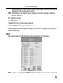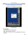
1
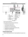
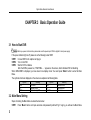
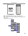
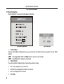
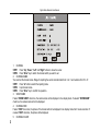
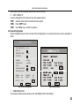
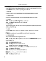
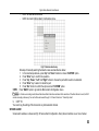
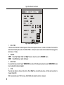
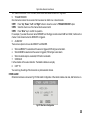
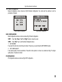
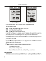
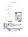
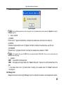
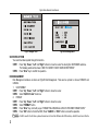
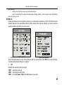
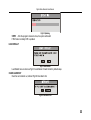
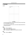
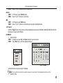
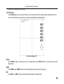
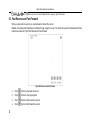
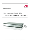
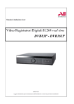
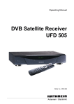
DVR User Manual
The guide is tailored for H.264-100 FPS /120 FPS 4-channel digital video recorder.
All rights reserved.
Digital Video Recorder User Manual
CONTENTS
CHAPTER 1 Introduction ........................................................................................................................................................1
1.1 DVR Introduction ................................................................................................................................................................1
1.2 Main Features and Specification.........................................................................................................................................1
CHAPTER 2 Panel Function ...................................................................................................................................................3
2.1 Check the Accessories .......................................................................................................................................................3
2.2 Front Panel & Interface Terminals.......................................................................................................................................3
2.3 Back Panel & Interface Terminals .......................................................................................................................................4
2.4 Remote Controller Introduction ...........................................................................................................................................5
2.4.1 Use Remote Controller.......................................................................................................................................................................................5
2.4.2 Facie of Remote Controller ................................................................................................................................................................................6
CHAPTER 3 Basic Operation Guide ....................................................................................................................................10
3.1 How to Start DVR..............................................................................................................................................................10
3.2 Main Menu Setting............................................................................................................................................................10
3.2.1 Basic Configuration ..........................................................................................................................................................................................12
3.2.2 Live Configuration ............................................................................................................................................................................................13
3.2.3 Record Configuration .......................................................................................................................................................................................15
3.2.4 Alarm Configuration..........................................................................................................................................................................................17
3.2.5 PTZ Configuration ............................................................................................................................................................................................22
3.2.6 User Configuration ...........................................................................................................................................................................................23
3.2.7 Network Configuration......................................................................................................................................................................................25
3.2.8 Manager Tools..................................................................................................................................................................................................29
3.3 Shortcut Menu ..................................................................................................................................................................34
3.3.1 PTZ ..................................................................................................................................................................................................................34
3.3.2 Search..............................................................................................................................................................................................................35
3.3.3 Information .......................................................................................................................................................................................................40
3.3.4 Other ................................................................................................................................................................................................................41
CHAPTER 4 Remote Surveillance........................................................................................................................................42
4.1 Accessing DVR .................................................................................................................................................................42
4.1.1 Accessing DVR in LAN.....................................................................................................................................................................................42
i
Digital Video Recorder User Manual
4.1.2 Accessing DVR in WAN ...................................................................................................................................................................................43
4.2 Main Interface ...................................................................................................................................................................45
4.2.1 Login ................................................................................................................................................................................................................46
4.2.2 Snap Picture ....................................................................................................................................................................................................46
4.2.3 Parameter Settings ..........................................................................................................................................................................................46
4.2.4 Record .............................................................................................................................................................................................................46
4.2.5 Camera Audio ..................................................................................................................................................................................................46
4.2.6 DVR Status Panel ............................................................................................................................................................................................46
4.3 Remote Playback and Search ..........................................................................................................................................47
4.3.1 Remote Playback .............................................................................................................................................................................................47
4.3.2 Other Functions................................................................................................................................................................................................49
4.4 Remote DVR Configuration ..............................................................................................................................................52
4.4.1 Basic Configuration ..........................................................................................................................................................................................53
4.4.2 Live Configuration ............................................................................................................................................................................................54
4.4.3 Record Configuration .......................................................................................................................................................................................55
4.4.4 Alarm Configuration..........................................................................................................................................................................................57
4.4.5 Network Configuration......................................................................................................................................................................................57
4.4.6 User Configuration ...........................................................................................................................................................................................57
4.4.7 Manage Tools...................................................................................................................................................................................................57
4.5 Remote PTZ .....................................................................................................................................................................58
CHAPTER 5 Operation with Mouse .....................................................................................................................................62
5.1 Switch the Display of Channel ..........................................................................................................................................62
5.2 Enter the Menu List...........................................................................................................................................................62
5.2.1 Search..............................................................................................................................................................................................................62
5.2.2 Configuration....................................................................................................................................................................................................62
5.2.3 PTZ Control......................................................................................................................................................................................................63
5.3 Fast Reverse and Fast Forward .......................................................................................................................................64
CHAPTER 6 Frequently Asked Questions ..........................................................................................................................65
Appendix A Main Standard & Parameter ............................................................................................................................66
Appendix B Record Capability ............................................................................................................................................68
Appendix C Abbreviation .....................................................................................................................................................69
ii
Digital Video Recorder User Manual
CHAPTER 1 Introduction
1.1 DVR Introduction
This DVR adopts the unique solution of Dual Stream technology, with a main processor that can process the signal of DVR
recording and signal of internet transmission simultaneously, utilizing standard H.264 algorithm, the latest advanced video
compression format. The solution allows DVR to have powerful internet function of remote controlling DVR completely,
good internet speed, and high quality picture recording with very low bit rate, saving HDD space with long hour recordings.
1.2 Main Features and Specification
LIVE SURVEILLANCE
•
Support channel security by hiding live display
•
Display the local record state and basic information
•
Two level password control: administrator and common user
COMPRESSION FORMAT
Standard H.264.
RECORD MEDIA
The DVR supports to install one IDE HDD to record only.
BACKUP
•
Support to backup via USB to USB flash memory
1
Digital Video Recorder User Manual
•
Support to backup remotely by network client
RECORD & PLAYBACK
•
Record modes: Manual operation, Sensor detection, Schedule Record and Motion detection
•
Support HDD recycle
•
Support single channel playback
•
Support deleting and locking the record
•
Support remote playback in Network Client through LAN or internet
•
Two record search mode: time search and event search
ALARM
4 alarm inputs and 1 alarm output.
PTZ CONTROL
•
Support various PTZ protocols
•
Support various PTZ preset
•
Support remote PTZ control
COMMUNICATION PORT
RS 485 communication port.
NETWORK
•
Support TCP/IP protocol
•
Support remote DVR configuration
•
Support static IP, dynamic IP (DHCP) and PPPoE
•
On-time live surveillance, remote playback, remote backup
•
Remote PTZ control and Preset
•
Support IE browser for Network Client software
2
Digital Video Recorder User Manual
CHAPTER 2 Panel Function
Please make sure DVR is powered off before you connect the DVR with other equipment.
Do not hot plug in!
2.1 Check the Accessories
When you receive the machine, please check accessories and make sure you have all the parts.
Normally, accessories include: a mouse, a power cable, a CD-ROM with ‘Network Client’ software and some screws for
installing HDD.
You could use screwdriver and some screws to fix the HDD into DVR. The DVR can connect one HDD only.
2.2 Front Panel & Interface Terminals
The buttons on the Front Panel please refer to the entity. There might be slightly difference from below figures. You could
contrast below figure to the entity for realizing the function of every button.
The Front Panel and interface terminal is shown as Fig2.1 Front Panel.
3
Digital Video Recorder User Manual
1
3
5
7
9
11
13
HDD tray
2
Number buttons
Menu /Number Add button
4
PTZ /Del /Number Decrease button
Manual record /Focus button
6
Search /Zoom button
Play/Iris button
8
Fast backward /Speed button
Fast forward /Input Mode button 10 Stop /ESC button
Indicator lights
12 Enter button
Left /Up /Right /Down buttons
14 USB interface
Fig2.1 Front Panel
"A" button is used to switch the inputting mode.
LED has six indicator lights. The function of indicator lights is described as below:
•
•
•
•
•
•
The first light will be on when the DVR is powered on.
The second light will flicker when HDD is written or read.
The third light will be on when you backup information in DVR.
The fourth light will be on when a computer connects with the DVR via the network.
The fifth light will be on when the DVR is playing back.
The sixth light will be on when the DVR is recording.
2.3 Back Panel & Interface Terminals
The interfaces on the Back Panel please refer to the entity. There might be slightly difference from below figure. You could
4
Digital Video Recorder User Manual
contrast below figure and the entity for realizing the function of every interface.
The Back Panel and interface terminal is shown as Fig2.2 Back Panel.
1
3
5
7
9
Power plug
2 Alarm in/alarm out
RS485
4 LAN port
Audio in 1-2
6 S-video output
Audio output 8 Video output
Video in 1-4
Fig2.2 Back Panel
2.4 Remote Controller Introduction
2.4.1 Use Remote Controller
Notice: Please note that Remote Controller is not a standard part of this DVR. Your package might not include it.
Steps of using the Remote Controller are described as below:
STEP1
Put the battery into the Remote Controller.
1. Open the battery cover of the Remote Controller.
2. Put into two AAA batteries whose model is 7 and make sure that they are not inserted upside down.
3. Put back the battery cover.
STEP2
Check the followings if the Remote Controller does not work.
−
Whether the battery’s anode and cathode are in the correct position or not.
−
Whether the power of the battery is ran out or not.
−
Whether there is barrier between the Remote Controller and DVR or not.
5
Digital Video Recorder User Manual
−
Whether there are some signals which transmitted by other devices disturbing the Remote Controller or
not.
Notice: If the possibilities above are excluded, please contact with vendor to change the Remote Controller.
2.4.2 Facie of Remote Controller
The entire facie of the Remote Controller is shown in Fig2.3 Remote Controller.
Fig2.3 Remote Controller
All buttons on the Remote Controller describes as below table. You could use "A" button on the Remote Controller to
switch the input mode.
Button
Name
POWER
REC
INFO
6
Description
Power Button
Press the button to shutdown the DVR.
Record Button
If the DVR does not record, press the button to start recording. If the DVR is recording, press the button to stop
recording.
Information Button
Press the button to display state information of the DVR on the screen.
Digital Video Recorder User Manual
Button
Name
1-16
1X1
2X2
3X3
4X4
MENU
SEARCH
Upward
Leftward
Rightward
Downward
SR SF
-SET+
Play
Description
Number Buttons
These number buttons are used for selecting channels and other functions.
Full-screen display mode
Press the button to display the picture of single channel.
Four-screen display mode
Press the button to display the picture of four channels. Press "1X1" button in four-screen display mode to enter
the channel 1.
Nine-screen display mode
Press the button to display the picture of nine channels. Press "1X1" button in nine-screen display mode to
enter the channel 1.
Sixteen-screen display mode
Press the button to display the picture of sixteen channels. Press "1X1" button in sixteen-screen display mode
to enter the channel 1.
Menu button
Press the button to enter the main menu (referred Fig3.2 Main Menu). Otherwise press the button to return the
previous menu or exit the menu.
Search button
Press the button to enter to recording search page.
Up button
Press the button to upward move the cursor.
Left button
Press the button to leftward move the cursor.
Right button
Press the button to rightward move the cursor.
Down button
Press the button to downward move the cursor.
Play for single frame button
Press the left SR to go back by single frame. Press the right SF to go forward by single frame.
Switch for channel button
Press the button to switch the channel one by one. "-" is used to display next bigger number channel, and "+" is
used to display next smaller number channel. You also can switch the channel by pressing number buttons.
Play and Pause button
Press the button to play record. Press the button once again to pause record.
7
Digital Video Recorder User Manual
Button
Name
Fast backward
Fast reverse button
Press the button to backward play the record. There are three backward multiple to choose: 2X, 4X, 8X.
Fast forward
Fast forward button
Press the button to forward play the record. There are three forward multiple to choose: 2X, 4X, 8X.
Stop
Stop button: Press the button to stop playing record.
Audio switch
Audio switch button
Press the button to switch the audio of the channel.
SEQ
Sequence Button
Press the button to make DVR display channels in turn.
A
PTZ
8
Description
A Button
Press the button to switch the mode of font form.
PTZ button
Press the button to enter the PTZ mode.
Zoom+/-
Zoom button
Control the Fast Speed Dome to zoom-in and zoom out.
FOCUS+/-
FOCUS button
Control the focus of the Fast Speed Dome.
IRIS+/-
Aperture button
Control the input lightness of theFast Speed Dome.
Digital Video Recorder User Manual
Button
Name
SPEED+/-
Description
SPEED- button
Control the rotational speed of the Fast Speed Dome.
The following table shows all letters which number buttons correspond.
Number Button
1
3
5
7
9
Corresponding Letter
().@<>
DEF/def
JKL/jkl
PQRS/pqrs
WXYZ/wxyz
Number Button
2
4
6
8
Corresponding Letter
ABC/abc
GHI/ghi
MNO/mno
TUV/tuv
9
Digital Video Recorder User Manual
CHAPTER 3 Basic Operation Guide
3.1 How to Start DVR
Notice: Before you power on the machine, please make sure the power input of DVR is eligible for local power supply.
If the power indicator light is off, please do as the following to start DVR:
STEP1 Connect DVR to AC adaptor and plug in.
STEP2 Turn on the DVR.
STEP3 Wait for DVR to initialize.
After the DVR is powered on, ‘STARTING……’ appears on the screen, which indicates DVR is initializing.
When ‘WELCOME’ is displayed, you have been in live display mode. You could press "Menu" button to enter the Main
Menu.
The symbols which are displayed on the screen are explained as following table.
Symbol
LIVE
A
DISK
Meaning
Live state
Sensor record
Ratio of using HDD
Symbol
REC
M
V-LOSS
Meaning
Manual record
Motion record
Video loss
3.2 Main Menu Setting
Steps of entering the Main Menu are described as below:
STEP1 Press "Menu" button and input username and password (referred Fig3.1 Login), you will see the Main Menu
10
Digital Video Recorder User Manual
(referred Fig3.2 Main Menu).
MAIN MENU
BASIC CONFIG
LIVE CONFIG
RECORD CONFIG
ALARM CONFIG
PTZ CONFIG
USER CONFIG
NETWORK
MANAGER TOOLS
Fig3.1 Login
Fig3.2 Main Menu
STEP2 Press "Up", "Down", "Right" and "Left" buttons to move cursor, selection highlighted by yellow.
STEP3 Press "Enter" key to enter the sub-menu. And press "Menu" key to get back to Main Menu when you use the
front panel to operate.
The structure of the main menu is shown in Fig3.3.
11
Digital Video Recorder User Manual
Fig3.3 Structure of Main Menu
3.2.1 Basic Configuration
Basic Configuration menu is shown as Fig3.4 Basic Configuration.
Fig3.4 Basic Configuration
Fig3.5 Time Adjust
1. VIDEO FORMAT
After you enter the Basic Configuration menu, you need to set the video format. There are two options to choose: NTSC
and PAL.
STEP1 Press "Up", "Down", "Left" and "Right" buttons to move the cursor manually.
STEP2 Press "Enter" key to change the video format.
2. TIME POSITION
You could set position of displaying time. There are three options to choose:
•
•
•
3.
12
TOP: Time is displayed on top of the screen.
BOTTOM: Time is displayed at the bottom of the screen.
NO: Do not display time on the screen.
DVR NAME
Digital Video Recorder User Manual
You could set DVR name. Range for inputting the words contents letters from ‘a’ to ‘z’ and numbers from ‘0’ to ‘9’.
STEP1 Press "A" button to switch the inputting mode
STEP2 Modify the DVR name.
STEP3 Press "Enter" key to confirm the operation.
4. DVR ID
You could set DVR ID. It consists of three numbers.
STEP1 Press "Up", fDown", "Left" and "Right" buttons to move the cursor.
STEP2 Press "Enter" key to modify numbers.
STEP3 Input three numbers, and press "Enter" key to confirm modifying the parameter.
STEP4 Press "OK" button to confirm the operation.
5. DATE FORMAT
There are three options to choose:
•
•
•
Asian Date format: YY/MM/DD.
European Date format: DD/MM/YY.
American Date format: MM/DD/YY.
6. TIME ADJUST
Time Adjust menu is shown as Fig3.5 Time Adjust. You must stop recording first to adjust time.
STEP1 Press "Up", "Down", "Left" and "Right" buttons to move the cursor.
STEP2 Use the numbers to modify time.
You also can use "+" and "-" button to modify time.
STEP3 Press "Enter" key to confirm the operation.
Notice: If time that you adjust is less than current time, the record between adjusted time and current time will be delete automatically.
7. BUZZER ALARM
You could set continual time for buzzer alarm. There are seven options to choose: always, 5 seconds, 10 seconds, 30
seconds, 1 minute, 2 minutes and 4 minutes.
3.2.2 Live Configuration
Live Configuration menu is shown as Fig3.6 Live Configuration.
13
Digital Video Recorder User Manual
Fig3.6 Live Configuration
1. CHANNEL
STEP1 Press "Up", "Down", "Left" and "Right" buttons to move the cursor.
STEP2 Press "Enter" key to switch the channel which you want to set.
2. CHANNEL NAME
You could set the channel name. Range for inputting the words contents letters from ‘a’ to ‘z’ and numbers from ‘0’ to ‘9’.
STEP1 Press "A" button to switch the inputting mode.
STEP2 Input channel name.
STEP3 Press "Enter" key to confirm the operation.
3. SHOW NAME
If select "SHOW NAME" check box, the camera name will be displayed in live display mode. If unselect "SHOW NAME"
check box, the camera name will not be displayed.
4. CHANNEL HIDE
If select "HIDE" check box, the picture of the channel will not be displayed in live display mode. But it is also recorded. If
unselect "HIDE" check box, the picture will be displayed.
5. CHANNEL COLOR
14
Digital Video Recorder User Manual
Modify value of contrast, brightness, saturation and hue of the picture.
6. COPY CONFIG TO
Copy the configurations of this channel to any other selected channel.
STEP1 Select the channel which this channel will be copied to.
STEP2 Press "COPY" button.
STEP3 Press "Enter" key to confirm the operation.
3.2.3 Record Configuration
Record Configuration menu is shown as Fig3.7 Record Configuration. You could enter the menu to set the parameters of
record.
RECORD CONFIG
VIDEO RESOLUTION :
RECYCLE
<CIF>
:
PRERECORD TIME
:
TIME STAMP
:
CHANNEL
VIDEO QUALITY
:
:
AUDIO
:
<15 S>
<CAM1>
<HIGHEST>
SCHEDULE RECORD :
FRAME RATE SETUP :
MANUAL:
MOTION:
COPY TO:
<25>
<25>
SETUP
(FPS)
SCHEDULE:
SENSOR :
<ALL>
OK
<25>
<25>
COPY
CANCEL
Fig3.7 Record Configuration
Fig3.8 Schedule Setup
1. VIDEO RESOLUTION
The resolution of different video format are: PAL: 352*288(CIF); NTSC: 352*240(CIF).
15
Digital Video Recorder User Manual
2. RECYCLE
If select "RECYCLE" check box to have continuous recording, DVR will overwrite the oldest record when HDD is full. If you
unselect "RECYCLE" check box, the DVR will stop recording when the HDD is full.
3. TIME STAMP
If selecting the check box, record time will be displayed on the bottom of screen when playing back the record.
4. PRERECORD TIME
Prerecord time is the record time before alarm. There are two options to choose: 5 seconds and 10 seconds.
5. CHANNEL
STEP1 Press "Up", "Down", "Left" and "Right" buttons to move the cursor.
STEP2 Press "Enter" key to switch the channel which you want to set.
6. VIDEO QUALITY
There are five options to choose: lowest, lower, medium, higher and highest. Higher picture quality is, the picture is clearer.
And the rate of using HDD is larger.
7. AUDIO
If you select "AUDIO" check box, DVR will record audio when it records video. Otherwise it will not record audio.
Notice: When you playback the record, you can press "AUDIO" button to switch the sound of corresponding channel.
8. SCHEDULE RECORD
Setting of the Schedule Record is shown as Fig3.8 Schedule Setup.
STEP1 Press "Up", "Down", "Left" and "Right" buttons to move the cursor to "SCHEDULE RECORD" option in the
Record Configuration menu.
STEP2 Select "SCHEDULE RECORD" check box.
STEP3 Press "Setup" button to enter the Schedule Setup menu.
Press "ESC" button on the front panel to get back to upper menu.
STEP4 In the Schedule Setup menu, press "Up", "Down", "Left" and "Right" buttons to move the cursor.
STEP5 Press "Enter" key to enter the time set.
STEP6 Press "+" and "-" buttons on the front panel to modify the time.
Notice: When you use the mouse, you need roll to middle wheel to modify the time.
STEP7
16
Press "Enter" key to confirm the setup.
Digital Video Recorder User Manual
On weekday and holiday, you can select record whole day or set four periods of time to record.
9. FRAME RATE SETUP
Frame rate is the recording picture amount per second. If you choose 15, the picture recording rate is 15 frames per
second.
You could set frame rate for different record mode.
If the video format is NTSC, there will be five frame rates to choose: 1, 3, 7, 15 and 30. The maximum of the frame rate is
30.
If the video format is PAL, there will be five frame rates to choose: 1, 3, 6, 12 and 25. The maximum of the frame rate is 25.
10. COPY TO
You could copy the setting of this channel to any other selected channel.
3.2.4 Alarm Configuration
Alarm Setup menu is shown as Fig3.9 Alarm Configuration. You could enter the submenu to set the parameters of the
alarm.
MOTION ALARM
Motion Alarm submenu is shown as Fig3.10 Motion Alarm Configuration.
Fig3.9 Alarm Configuration
Fig3.10 Motion Alarm Configuration
17
Digital Video Recorder User Manual
1. HOLD TIME
It sets the record time after the alarm happened. There are two options to choose: 1 minute and 2 minutes. It also sets the
distant time of detecting the motion. If the HOLD TIME is 1 minute, the motion which is detected will only trigger the alarm
once in 1 minute.
2. CHANNEL
STEP1
Press "Up", "Down", "Left" and "Right" buttons to move the cursor.
STEP2 Press "Enter" key to switch the channel which you want to set.
3. DETECTION
"DETECTION" checked means to motion detection activated, unchecked means to motion detection disabled.
4. SENSITIVITY
It is the sensitivity of the motion detection.
The range is from ‘1’ to ‘8’. The bigger value is, the sensitivity is higher.
5. TO REC
If select "TO REC" check box, DVR will record when there is motion event. If not, DVR will not record.
6. ALARM OUT
There are two alarms out options to choose: ALARMOUT1 and BUZZER.
7. SCHEDULE
It is the schedule of the motion detection. The default schedule is everyday. Press "SETUP” button to set motion detection
schedule.
8. AREA
STEP1 Press "Up", "Down", "Left" and "Right" buttons to move the cursor.
STEP2 Press "SETUP" button to enter the Area Setup submenu.
It shows the setting of detection area (referred Fig3.11 Detection Area Setup). The fuchsia area means to be
unselected. The transparent live area means to be selected. There are four options of the Detection Area Setup
to choose:
−
ALL: All area will be detected.
−
CUSTOM: The part which you select will be detected.
18
Digital Video Recorder User Manual
−
−
NULL: No area will be detected.
BACK: Go back to Motion Alarm Configuration menu.
Fig3.11 Detection Area Setup
STEP3
Substeps of manually selecting the detection area are described as below:
1. In the Area Setup submenu, press "Up" and "Down" buttons to choose "CUSTOM" option.
2. Press "Enter" key to confirm the operation.
3. Press "Up", "Down", "Left" and "Right" buttons to choose the part which needs to be detected.
4. Press "Enter" key to select or cancel the part.
5. Press "Esc" button to confirm the option and exit "CUSTOM" option.
Press "BACK" option to go back the Motion Alarm Configuration menu.
Notice: In Continuous recording mode, Manual Record and Alarm Record are activated at the same time. If the Alarm Record occurs, the DVR
remains recording continuously. You can find the alarm event through ‘3.3.2 Search’ function of ‘3 Search by Event’.
9. COPY TO
You could copy the setting of this channel to any other selected channel.
SENSOR ALARM
Sensor alarm submenu is shown as Fig3.12 Sensor Alarm Configuration. Every Sensor matches one or more channel.
19
Digital Video Recorder User Manual
Fig3.12 Sensor Alarm Configuration
1. HOLD TIME
It sets the record time after the alarm happened. There are two options to choose: 1 minute and 2 minutes. It also sets the
distant time of detecting the motion. If the HOLD TIME is 1 minute, the sensor event which is detected will only trigger the
alarm once in 1 minute.
2. SENSOR
STEP1 Press "Up", "Down", "Left" and "Right" buttons to move the cursor to "SENSOR" option.
STEP2 Press "Enter" key to switch the Sensor.
3. DETECTION
It is a switch of sensor alarm. If select "DETECTION" check box, DVR will begin detecting. If unselect "DETECTION" check
box, the detection function is disabled.
4. TYPE
There are two options to choose: high and low. Press "Enter" key to enter the sub-menu. And there are two options to
choose: NO and NC.
‘NO’ means normal open. If ‘NO’ is chosen, the DVR will alarm when the alarm is in low level.
20
Digital Video Recorder User Manual
‘NC’ means normal close. If ‘NC’ is chosen, the DVR will alarm when the alarm is in high level.
5. TRIGGER RECORD
One channel can connect to one sensor. But one sensor can match one or more channels.
STEP1 Press "Up", "Down", "Left" and "Right" buttons to move the cursor to "TRIGGER RECORD" option.
STEP2 Select the check box of the channel which sensors match.
STEP3 Press "Enter" key to confirm the operation.
For example, if you select the sensor named SENSOR1 and the trigger records named CAM1 and CAM2, it will record on
channel 1 and channel 2 when the SENSOR1 is triggered.
6. ALARM OUT
There are two options to choose: ALARMOUT1 and BUZZER.
•
•
•
When ALARMOUT1 is selected and the sensor is triggered, DVR will give normal alarm.
When BUZZER is selected and the sensor is triggered, DVR will give buzzer alarm.
When the alarm output is unselected, DVR will not send alarm.
7. SCHEDULE
It is the schedule of the sensor detection. The default schedule is everyday.
8. COPY TO
You could copy the setting of this channel to any other selected channel.
OTHER ALARM
Other Alarm submenu is shown as Fig3.13 Other Alarm Configuration. Other alarm includes video loss, disk full and so on.
Fig3.13 Other Alarm Configuration
21
Digital Video Recorder User Manual
There are two options of alarm output: ALARMOUT1 and BUZZER.
3.2.5 PTZ Configuration
PTZ Configuration menu is shown as Fig3.14 PTZ Configuration.
Fig3.14 PTZ Configuration
Fig3.15 Preset
1. CHANNEL
Switch to the channel which connects to the Speed Dome.
2. BAUDRATE
There are five options of baudrate to choose: 1200, 2400, 4800, 9600 and 19200.
3. PROTOCOL
Choose the PTZ protocol. Currently support protocol: PELCO_D, PELCO_P, MINKING, NEON, STAR, VIDO, DSCP,
VISCA and LILIN.
4. ADDR
Set the PTZ address. Press "Enter" key and use the number key, "+" and "-" button to set it.
5. PRESET
STEP1 Press "SET" button to enter the Preset submenu which is shown as Fig3.15 Preset. There are 16 Presetting
Points which could be set in every channel.
STEP2 In the Preset submenu, press "Enter" button to switch the Presetting Point which needs to be reset.
STEP3 Press "ADJUST" button to enter the PTZ mode.
STEP4 On the front panel, press "ZOOM", "FOCUS", "SPEED", "IRIS", "+" (MENU) and "-" (PTZ) buttons to modify
22
Digital Video Recorder User Manual
position of the Presetting Point.
STEP5 Press "UP", "DOWN", "RIGHT" and "LEFT" buttons to rotate the Speed Dome.
STEP6 Press "ESC" button to come back the Preset menu.
STEP7 Press "SAVE" button to save the position of camera which you adjust before as Presetting Point; press
"CANCEL" button to discard the setting to get back to upper menu.
Notice: Do you know how to use the Presetting Point?
You can use the number key to switch the Presetting Point in PTZ mode. Firstly, press "PTZ" button to enter the PTZ mode. Then you
should press the number key such as "1", the Speed Dome will move to Presetting Point 1 which you set it in front steps.
6. COPY TO
You could copy the setting of this channel to any other selected channel.
3.2.6 User Configuration
User Configuration is shown as Fig3.16 User Configuration. The default username is Admin. Admin can add users, set
users’ authorizations and delete users.
AUTHORITY SETUP
USER CONFIG
AUTHORIZATION
CHECK
:
USER
:
PASSWORD
:
RESET
AUTHORIZATION
:
SETUP
:
ADD
:
DEL
NEW
USER
DELETE
USER
OK
<14>
CANCEL
Fig3.16 User Configuration
LOCAL AUTHORITY:
PLAY OR BACKUP
DEL OR LOCK
EVENTLOG
MANAGER TOOLS
RECORD
SETUP
PTZ CTRL
REMOTE AUTHORITY:
PLAY OR BACKUP
DEL OR LOCK
EVENTLOG
MANAGER TOOLS
RECORD
SETUP
PTZ CTRL
PREVIEW
MAC:
00-00-00-00-00-00
DEFAULT
OK
CANCEL
Fig3.17 Authority Setup
23
Digital Video Recorder User Manual
1. AUTHORIZATION CHECK
If select "AUTHORIZATION CHECK" check box, all users need input the password before entering the Main Menu.
If unselect "AUTHORIZATION CHECK" check box, users can enter the system directly without password.
2. USER
Press "Enter" key to switch to another user. Using "+” and "-" buttons could also change the user.
3. PASSWORD
Admin’s password is initialized as ‘123456’. Users with authorization change this user’s password. Password consists of
numbers between 0 and 9.
4. AUTHORIZATION
STEP1 Move the cursor to "User" option, and press "Enter" key to switch the user who you want to modify
authorization.
STEP2 Move the cursor to "SETUP" button on the screen.
STEP3 Press "Enter" key, Authority Setup menu (referred Fig3.17 Authority Setup) pops up.
STEP4 In the Authority Setup menu, move the cursor to the "DEFAULT" button.
STEP5 Press "Enter" key. The default authorization will be set.
The default authorization of user content:
−
Live view, Playback or backup and Record in local system.
−
Live view, Playback or backup and Record in remote Network Client.
5. NEW USER
STEP1 Move the cursor to "ADD" button on the screen.
STEP2 Press "Enter" key, the Add User menu will display.
STEP3 Input username and password.
STEP4 Press "OK" button to confirm the option.
Username can consist of numbers and letters, with 15 characters maximum. Password consists of numbers between 0
and 9.
6. DELETE USER
STEP1 Move the cursor to the "DEL" button on the screen.
STEP2 Press "Enter" key to confirm the operation. When a user is deleted, the username and password won’t exist in
the system any more.
24
Digital Video Recorder User Manual
3.2.7 Network Configuration
Network Configuration menu is shown as Fig3.18 Network Configuration. You could enter the submenu to set the
parameters of network.
Fig3.18 Network Configuration
Fig3.19 Basic Configuration
BASIC CONFIGURATION
Basic Configuration submenu is shown as below Fig3.19 Basic Configuration.
STEP1 Press "Up", "Down", "Left" and "Right" buttons to move the cursor.
STEP2 Press "Enter" key to enter the Basic Configuration menu.
1. NET SERVER
If you select the check box and set the port number of the server, you would make the NET SERVER enable.
2. NET VIDEO QUALITY
It sets picture quality of remote surveillance. There will be three options to choose: low, medium and high. The higher
quality value is, the picture is clearer.
IP CONFIGURATION
IP Configuration submenu is shown as Fig3.20 IP Configuration.
25
Digital Video Recorder User Manual
Fig3.20 IP Configuration
Fig3.21 System Information
It is the IP configure of the DVR. There are three options to choose: STATIC, DHCP and PPPoE.
Take Static IP address as example.
STEP1 Press "Up", "Down", "Left" and "Right" buttons to move the cursor.
STEP2 Input IP Address, Subnet Mask and Gateway.
STEP3 Press "OK" button to modify the IP Configuration menu.
If select DHCP, the IP address will be automatically assigned by local network. After selecting DHCP, you need to be
patient for waiting 30 second. The automatic assigned IP will be displayed on the system information window.
If select PPPoE, you need to set username and password when DVR need to connect internet. If you forget username and
password, Please contact with ISP.
If you press "INFO" button, the System Information menu can be displayed on the screen when DVR connects the network
successfully (referred Fig3.21 System Information).
Notice: • If the network of DVR is subjected to the following items, we recommend using Dynamic IP.
1. The local area network has DHCP server.
2. DVR can get IP address automatically from internet.
• Before you set PPPoE, you’d better reboot the modem. After setting the PPPoE, you need wait for a while.
DDNS CONFIGURATION
DDNS Configuration submenu is shown as Fig3.22 DDNS Configuration. The DVR supports DDNS server-‘88IP.net’. To
26
Digital Video Recorder User Manual
Use DDNS, user need to get a domain name from the ISP whose protocol is packed in DVR.
Fig3.22 DDNS Configuration
Notice: The actual ISP list may be different from each vendor.
Take the ‘dns2p.com’ as example to introduce. If different from the below example, please connect with your Domain
Name Service Provider to be guided how to get the domain.
1. Apply the Domain Name
(1) Register in the Web
STEP1 Fill in the blank of IE address with ‘www.dns2p.com’.
STEP2 Click
to enter the website.
STEP3 Click "New User" in the right of homepage to register. For example: User ID is ‘abc’, and password is ‘123456’
(referred Fig3.23 Register Page).
27
Digital Video Recorder User Manual
Fig3.24 Login Page
Fig3.23 Register Page
(2) Login
STEP1 Return to homepage after registering successfully.
STEP2 Click "Account Manager" on the right of homepage to login (referred Fig3.24 Login Page).
STEP3 Input the username and password with the information that you have registered.
STEP4 Click "Enter" key after filling in the textbox.
(3) Domain Setup
STEP1 Click "Domain Management" on the left to set the domain (referred Fig3.25 Domain Setup).
Fig3.25 Domain Setup
STEP2
STEP3
28
Input the domain in the textbox. For example, you set ‘dvr’ as the domain.
Click "Submit" button, the system will pop up a dialog box to show that the domain is added successfully
Digital Video Recorder User Manual
(referred Fig3.26 Dialog Box).
Fig3.26 Dialog Box
Notice: Time of probationary period is one month. If user wants to use it continuatively after one month, please click "Buy Now" in the right of
homepage to pay for it.
2. Setup in the DVR
(1) DOMAIN
Domain is set in ‘1 Apply the Domain Name’. According to the example above, the domain is ‘dvr.dns2p.com’.
(2) USER ID
Username of registered which is set in ‘(1) Register in the Web’. According to the example above, user ID is ‘abc’.
(3) PASSWORD
Password is set in ‘(1) Register in the Web’. According to the example above, password is ‘123456’.
Notice: If the connection fails, press the "INFO" button, the system will display: ‘DDNS NONE’. Then you need to check network and
information above and try again.
3. Application
STEP1 Connect DVR to the Network Client.
STEP2 After popping up the login interface, fill in "Server" textbox with ‘ *.dns2p.com’ to visit the Network Client of the
DVR.
‘*’ is the domain which is set in ‘(3) Domain Setup’. According to the example above, fill in "Server" textbox with
‘ dvr.dns2p.com’.
3.2.8 Manager Tools
Manager Tools menu is shown as Fig3.27 Manager Tools. You could enter the submenu to set the parameters of network.
29
Digital Video Recorder User Manual
Fig3.27 Manager Tools
Fig3.28 Disk Management
SHUTDOWN SYSTEM
You could shut down system through this function.
STEP1 Press "Up", "Down", "Left" and "Right" buttons to move the cursor for entering the SHUTDOWN submenu.
The following words will be shown: ‘ARE YOU SURE TO SHUT DOWN DVR SYSTEM?’.
STEP2 Press "Enter" key to confirm the operation.
DISK MANAGEMENT
Disk Management submenu is shown as Fig3.28 Disk Management. There are two options to choose: FORMAT and
CANCEL.
1. UICK FORMAT
STEP1 Press "Up", "Down", "Left" and "Right" buttons to move the cursor.
STEP2 Select "QUICK Format" check box.
2. FORMAT
STEP1 Press "Up", "Down", "Left" and "Right" buttons to move the cursor.
STEP2 Select "FORMAT" button.
STEP3 Press "Enter" key, a hint will pop up: ‘FORMAT WILL ERASE ALL DATA ON THIS HDD! FORMAT NOW? ’
STEP4 Press "OK" button to format the HDD; Press "CANCEL" or "ESC" button to cancel this operation.
Notice: • If HDD is used for the first time, system will remind user to format the HDD when the DVR started up. And HDD could record after the
30
Digital Video Recorder User Manual
HDD is formatted.
• Before you format the HHD, you must stop recoding and playing back.
• Time for formatting the HDD is subjected to the HDD capability. The bigger capability is, the time is longer. Normally, a 40G HDD takes
about eighty seconds to format.
SYSTEM LOG
System log submenu is shown as Fig3.29 Log Search. You could inquire the operation log on DVR. The DVR will note the
operation, status and time automatically when the DVR is working. After enter the submenu, you need to select the
operation and status type which you need to inquire.
Fig3.29 Log Search
Fig3.30 System Information
1. TYPE
Types of the log file. Move the cursor to the log file types which you want to inquire, press "Enter" key to select the types.
The default setting is select all types. For example:
2. TIME
Beginning time and ending time of the log file.
STEP1 Select types of the log.
STEP2 Select start time and end time.
STEP3 Press "Up", "Down", "Right" and "Left" buttons to move cursor.
31
Digital Video Recorder User Manual
STEP4 Press "OK" button to view the event log; Press "CANCEL" or "ESC" button to cancel this operation.
The information of log files content start time, end time and log file types. For example: 110707:092151 means 2007-7-11
9:21:51 and N-L means the LOGIN of the NET.
If there are too much log list, user can use "PREV" button to page up and use "NEXT" button to page down.
SYSTEM INFORMATION
System information submenu is shown as Fig3.30 System Information. It displays the information about the system, such
as firmware version, device name, DVR IP ADDRESS, Client information and so on.
Press the "INFO" button on the front panel, it will display the system information on the screen.
UPDATE FIRMWARE
Fig3.31 Update Firmware
Update Firmware submenu is shown as Fig3.31 Update Firmware. You could use USB disk to update the firmware.
Before using USB disk to update, please make sure the firmware is in the USB disk. Steps are described as below.
STEP1 Make sure the updating firmware is in the USB disk.
STEP2 Enter the menu after word-‘USB’ is displayed on the live mode.
STEP3 Press "Up" and "Down" buttons to move the cursor on "UPDATE" button.
STEP4 Press "Enter" key to start updating.
Process of backup is shown as Fig3.32 Updating.
32
Digital Video Recorder User Manual
Fig3.32 Updating
STEP5 After the program checked is done, the system will restart.
If DVR reboot normally, DVR is updated.
LOAD DEFAULT
Fig3.33 Load Default
Load Default menu is shown as Fig3.33 Load Default. It loads the factory default setup.
CLEAR ALARM OUT
Clear the current alarm out, referred Fig3.34 Clear Alarm Out.
Fig3.34 Clear Alarm Out
33
Digital Video Recorder User Manual
3.3 Shortcut Menu
3.3.1 PTZ
Fig3.35 PTZ Mode
PTZ mode is shown as Fig3.35 PTZ Mode. In order to switch the channel to which connects the video output of the Speed
Dome, you may press "PTZ" button to enter the PTZ mode.
In the live view of PTZ mode, the default channel is channel 1, you can use mouse to change the channel number to enter
the corresponding channel PTZ mode.
SPEED
STEP1
STEP2
STEP3
In PTZ mode, press "Speed" button.
Press "+" and "-" buttons to change the rotational speed.
Press "Up", "Down", "Left" and "Right" buttons to rotate the Speed Dome to certain position.
ZOOM
STEP1
In PTZ mode, press "ZOOM" button.
34
Digital Video Recorder User Manual
STEP2
FOCUS
STEP1
STEP2
Press "+" and "-" buttons to zoom in and zoom out.
In PTZ mode, press "FOCUS" button.
Press "+" and "-" buttons to control focus.
IRIS
STEP1
STEP2
In PTZ mode, press "IRIS" button.
Press "+" and "-" buttons to control little and much light of the Speed Dome.
3.3.2 Search
Press the "Search" button, there are five submenus displayed on the screen: PLAYBACK, BACKUP, DELETE and LOCK.
Data menu is shown as Fig3.36 Data.
PLAYBACK
1. Select the Date
STEP1 In Data menu, press "Up" and "Down" buttons to move the cursor.
STEP2 Press "Enter" key to enter the Calendar submenu.
Fig3.36 Data
Fig3.37 Calendar
Calendar submenu is shown as Fig3.37 Calendar.
Notice: You can search the record which you need by time search or event search. The time displayed in red has record file.
2.
Search by Time
35
Digital Video Recorder User Manual
All the record can be searched through this function. Steps of search by time as below:
STEP1 In Calendar submenu, press "Up", "Down", "Right" and "Left" buttons to select date.
STEP2 Press "Enter" key to enter the Playback submenu, referred Fig3.38 Playback.
STEP3 Press "Enter" key to select channels.
STEP4 Press "Up", "Down", "Right" and "Left" buttons to select time of the date which you select ahead.
The time in red has record file. The first line is hour, and the second line is minute.
STEP5 Press "Up", "Down", "Right" and "Left" buttons to move the cursor, and select the "PLAY" button.
STEP6 Press "Enter" key to play the record.
Notice: • It just supports playing back in large picture mode. You may uset "Up", "Down", "Left" and "Right" buttons to switch the channels.
• When you play back the record, you may press "INFO" button on the front panel to play or stop channel audio.
Fig3.38 Playback
3. Search by Event
You could search the motion detection records and sensor alarm records through searching by event. Steps of searching
the event as below:
STEP1 In Playback submenu, select the camera and date. The date which has event record is highlighted in red.
STEP2 Press "Up", "Down", "Right" and "Left" buttons to move the cursor to event option.
Event search types: MOTION and SENSOR.
STEP3 Press "Down" button to move the cursor to "EVENTS" button in the submenu.
STEP4 Press "Enter" key to enter the event list.
STEP5 Analyze the list information.
Take one of the event records information as example. Meaning of the words is described as below:
36
Digital Video Recorder User Manual
STEP6
STEP7
STEP8
−
CH: Channel.
−
START TIME: The start time of the record.
−
TYPE: The type of the event. There are two types of event: MOTION and SENSOR.
−
M: Motion detection.
−
A: Sensor detection.
−
LOCK: Lock status of files.
Press "Up" and "Down" buttons to choose the event record.
Press "Enter" key to play back the record which is chosen.
Press "Stop" button to get back to live display mode.
Notice: If event list is over a page, use "PREV" and "NEXT" buttons to view next page.
BACKUP&VIEW BACKUP
1. BACKUP
Select the Backup submenu in the Data menu to enter the Backup submenu which is shown as Fig3.39 Backup.
Fig3.39 Backup
(1) BACKUP MEDIA
Press "Enter" button to modify the backup media which would backup the record. There are five options to choose: DVD-R,
DVD-RW, DVD+R, DVD+RW and USB disk. They connect with DVR through USB interface.
(2) BACKUP FILE
37
Digital Video Recorder User Manual
It selects the format of backup file. It supports AVI and DAT video format. When you select DVR, the video format of
backup file will be DAT.
(3) START TIME
Start recording time to backup. The first line is hour, and the second line is minute. You must choose the date firstly and
choose the time secondly.
(4) END TIME
End recording time to backup. The first line is hour, the second line is minute. You must choose the date firstly and choose
the time secondly.
(5) CHANNEL
If you want to backup one or more channels, please select the channels which you want to backup.
(6) EVENTS
There are two options to choose: motion and sensor. If you want to backup all records, please select "ALL".
(7) BACKUP
After selecting of BACKUP MEDIA, BACKUP FILE, CHANNEL, START TIME, END TIME and EVENTS, DVR is ready to
backup.
STEP1 Enter the menu after word-‘USB’ is displayed on the live mode.
STEP2 Press "BACKUP" button, the backup information of DVR will display on the screen (referred Fig3.40 Backup
Information).
BACKUP INFO
DEVICE
:USB
DEVICE TYPE
:USB DISK
AVAILABLE SPACE :400 MB
REQUIRED SPACE :64 MB
START TIME
:11-7-2007 20:21:52
END
TIME
:11-7-2007 20:22:17
EVENTS
:1
START
CANCEL
Fig3.40 Backup Information
STEP3
38
Press "START" button, backup starts.
Fig3.41 Backup Progress
Digital Video Recorder User Manual
Backup progress will be displayed on screen, as Fig3.41 Backup Progress. If you stop recording when you
backup the record files, the backup speed will be faster.
STEP4 When the backup is over, the system will pop up a dialog box. The sentence in the dialogue is as following:
‘BACKUP COMPLETELY’.
So far, the backup is completed.
2. VIEW BACKUP
If backup with AVI format, most media player can view directly.
If backup with DVR format, please use the client software to view.
(We also supply extra software, DVR player, which can play AVI and DVR format, it is suggested to utilize DVR player to
play both format recordings).
DELETE
Delete submenu is shown as Fig3.42 Delete. You can delete the selected record in the Delete submenu.
Fig3.42 Delete
STEP1
In Data menu, press "Up", "Down", "Right" and "Left" buttons to move the cursor, the submenu selected will be
39
Digital Video Recorder User Manual
displayed in yellow.
STEP2 Press "Enter" key to enter the Delete submenu.
STEP3 In the Delete submenu, use "UP" and "DOWN" buttons to move the cursor.
STEP4 Press "Enter" key to select the record.
STEP5 Move the cursor to "DELETE" button and press "Enter" key, information will be given as below:
‘SOME RECORDS WILL BE DELETED, CONTINUE?’
STEP6 Press "Left" and "Right" buttons to select "OK" button.
STEP7 Press "Enter" key to delete this record.
LOCK/UNLOCK
Lock submenu is shown as Fig3.43 LOCK/UNLOCK. It uses to lock or unlock the record.
Fig3.43 LOCK/UNLOCK
Use "Enter" key to change the state. If the record event is locked, the record can not be deleted and overwritten.
3.3.3 Information
Press the "INFO" button, there will be some information appearing on the screen. For example, HDD quantity, usable rate
40
Digital Video Recorder User Manual
of HDD, record mode including manual/alarm/motion etc.
3.3.4 Other
•
In live display mode, if you press the "Up" button, it will display the first channel in full screen.
•
If you press the "Down" button, it will display the second channel in full screen.
•
If you press the "Left" button, it will display the third channel in full screen.
•
If you press the "Right" button, it will display the fourth channel in full screen.
•
If you press the "Enter" button, it will display the four-divided channel.
•
If you press the "Audio" button, it will switch the voice for corresponding channel in live display mode.
41
Digital Video Recorder User Manual
CHAPTER 4 Remote Surveillance
4.1 Accessing DVR
Because our DVR supports IE control, you need use IE connect to DVR and download and install ActiveX controls for
remote controlling the DVR.
Before remote controlling the DVR, you need right connect the DVR and cable to internet. If you access the DVR through
WAN, you need to set DVR and router parameters firstly.
DVR could support five users logging in and operating the Network Client synchronously.
4.1.1 Accessing DVR in LAN
When your computer is connected in LAN, you can access DVR according to following steps for using IE browser.
STEP1 Double-click the IE browser icon to open the IE browser.
STEP2 Input the IP address in IE textbox and press "Enter" key.
STEP3 Install ActiveX controls in displayed page.
STEP4 After finishing installing, the system will connect to DVR automatically. It will display Network Client interface,
referred Figure4-1 Network Client Interface.
42
Digital Video Recorder User Manual
Figure4-1 Network Client Interface
4.1.2 Accessing DVR in WAN
When you access DVR in WAN, you need to set safety certificate firstly.
STEP1 Double-click the IE browser icon to open the IE browser.
STEP2 Select ‘tools > Internet Options’ in menu bar, it will pop up "Internet Options" window, referred Figure4-2
Internet Optionss.
43
Digital Video Recorder User Manual
Figure4-3 Security Settings
Figure4-2 Internet Options
STEP3 Click "Security" option, and click "Custom Level…" in "Security level for this zone", it will pop up "Security
Settings" window, referred Figure4-3 Security Settings.
STEP4 In "Security Settings" window, enable the options which relate with ActiveX controls.
STEP5 Click "OK", finish setting the parameters.
STEP6 Input IP of the DVR in IE textbox, then press "Enter" key.
STEP7 Install ActiveX controls automatically in displayed page.
44
Digital Video Recorder User Manual
STEP8 The system access DVR automatically after finishing installation. The Network Client interface will be displayed
in IE browser, referred Figure4-1 Network Client Interface.
Notice: When the Network Client is running on VISTA operation system, you also need set relational ActiveX parameters. Steps of setting
parameters are shown as follows:
1. Open IE browser, then select ‘Internet Options > Advanced > Security’.
2. Enable ‘Allow software to run or install even if the signature is invalid’ and ‘Allow active content to run in files on my computer’.
3.Click "OK" to finish the settings.
4.2 Main Interface
The function button of the remote surveillance is shown as Fig4.2 Main Interface.
Fig4.2 Main Interface
45
Digital Video Recorder User Manual
4.2.1 Login
The operation of the Network Client is the same as the DVR. Default username is ‘Admin’ and password ‘123456’.
STEP1
STEP2
Click
button to input username and password in the pop-up box.
Press "Enter" key to login.
Notice: Click "EXIT" button, you could exit the system.
4.2.2 Snap Picture
Snap live picture. Press
to snap the picture.
4.2.3 Parameter Settings
Parameter Settings window could set the amount how many picture you snap once. If you select 5, you can snap five
pictures every time when you click "Snap Picture" button.
4.2.4 Record
STEP1 Click "DVR Record" button.
STEP2 Select "Start Record" in drag-down list to record.
STEP3 Select "Stop Record" in drag-down list to stop recording.
4.2.5 Camera Audio
You could set to open or close the camera audio.
STEP1 When you are in live display mode or playback mode, select a channel to display in Large Picture mode.
STEP2 Right-click the picture, and select "Open Audio" to play the camera audio.
STEP3
Click
button to turn up or turn down the audio.
4.2.6 DVR Status Panel
Meaning of the colors for indicator lights in the Main Interface are shown as below:
46
1.
Grey indicator light: Normal State.
2.
Green indicator light: Manual Record State.
3.
Yellow indicator light: Motion Detection Record State.
Digital Video Recorder User Manual
4.
Red indicator light: Sensor Alarm Record State.
5.
Blue indicator light: Video Loss State.
4.3 Remote Playback and Search
4.3.1 Remote Playback
Click
button in the Main Interface to enter the following area which is shown as Fig4.3 Remote Playback.
Fig4.3 Remote Playback
Meaning of the function button in the Remote Playback window is shown as below:
1.
: Play /Pause.
47
Digital Video Recorder User Manual
2.
3.
4.
: Stop.
: Next frame. This button will be valid when playback is paused.
You can select suitable speed for playing record in the area as Fig4.4 Multiple of Playing.
Fig4.4 Multiple of Playing
Fig4.5 Data Preview
Fig4.5 Data Preview shows the record data of different channels in corresponding time. In the figure, left side shows the
available channels. When certain channel has been selected for playback, the background color will be highlighted and ‘ ’
sign will appear beside the channel title.
The data preview area at the center gives details of the record files. Different colors of the bar show different types of
records. The following are the definitions of the color bars:
Blue: Manual Record Events
Green: Schedule Record Events
Yellow: Motion Detection Record Events
Red: Sensor Alarm Record Events
The ruler on top of the bar shows the hours in whole day. Right-click the ruler, it will be magnified 10 multiples. Therefore
users can see the time marks in details.
STEP1 When you search for a certain section of record, draw the bar to the desired position. If necessary, right-click the
bar to see the magnified time marks for precise search.
STEP2 Click
button to play the selected record.
When you return to live display mode after finishing remote playback, it will display word-‘connect…’ sometimes on the
screen. And you may click "Large Picture" or "Quad Picture" button to fresh screen to get live picture.
48
Digital Video Recorder User Manual
4.3.2 Other Functions
BACKUP
Click
button to enter the Backup window which is shown as Fig4.6 Backup.
Fig4.6 Backup
There are two methods of backup: backup by time and backup by event.
1. TIME BACKUP
STEP1 Select the time and record type.
STEP2 Select the camera.
STEP3 Press "Browse…" button to select the folder of saving the Backup file.
STEP4 Select cameras which you want to backup.
STEP5 Select the type of backup file.
STEP6 Click "Backup Now" button, backup progress pops up.
49
Digital Video Recorder User Manual
2. EVENT BACKUP
STEP1 Select the time and record type.
STEP2 Select the camera.
STEP3 Press "Browse…" button to select the folder of saving the Backup file.
STEP4 Select cameras which you want to backup.
STEP5 Select the type of backup file.
STEP6 Click "Select Event" button to enter the Select Event window which is shown as Fig4.7 Select Event.
Fig4.7 Select Event
1. Choose event list and press ">>" button to move to backup list, showed in the box under; Click ">>>>" to
choose all events.
2. Choose event list and press"<<" button to clear selected event; click "<<<<" button to clear all events.
50
Digital Video Recorder User Manual
STEP7
Click "OK" button to run the backup.
LOCK /UNLOCK
You could select the record which you want to lock/unlock.
STEP1
Click
button to enter the Remote Lock window, as Fig4.8 Remote Lock.
Fig4.8 Remote Lock
Fig4.9 Lock Event
STEP2 Select the time and record type.
STEP3 Select the camera.
STEP4 Click "Select Event" button, system find the corresponding event and it will pop up the LOCK EVENT window
which is shown as Fig4.9 Lock Event.
STEP5 Select the check box can change the lock status.
Lock Status shows ‘√’ to indicate that the event is locked, otherwise it means unlock.
STEP6 Click "OK" button to confirm the operation in the Lock Event interface.
51
Digital Video Recorder User Manual
4.4 Remote DVR Configuration
Click
button in the Main Interface to enter the following interface which is shown as Fig4.10 Remote DVR
Configuration.
Fig4.10 Remote DVR Configuration
The definitions of the buttons in Fig4.10 are as below:
System Configuration
Live configuration
Record Configuration
Alarm Configuration
PTZ Configuration
User Configuration
Manage Tools
52
Return
Digital Video Recorder User Manual
The Remote DVR Configuration can set the configurations of the DVR remotely. The operation is the same as DVR. It can
change the configuration of DVR.
4.4.1 Basic Configuration
Click
button in the Remote DVR Configuration and enter the Basic Configuration which is shown as below Fig4.11
Basic Configuration.
After you change parameters of the Basic Configuration window, click "OK" button, the setting will be saved and inured on
the DVR.
Fig4.11 Basic Configuration
1. Video Format
Select the option in the drag-down list to change the video format of DVR. There are two video format : PAL and NTSC.
2. Time Position
Select the option in the drag-down list to change the time position that displays on the DVR.
3. DVR Name
Input words to change the name of DVR.
53
Digital Video Recorder User Manual
4. DVR No.
When you have more than one DVR, you can give a number to every DVR.
5. Date Format
Select the option in the drag-down list to change the format of date. There are three date format : YY/MM/DD、DD/MM/YY
和 MM/DD/YY.
6. Buzzer
Select the option in the drag-down list to change the time how long the buzzer will last.
4.4.2 Live Configuration
button in the Remote DVR Configuration, the drag-down menu will appear. There are the Live Configuration
Click
window and Color Settings window which are shown as below Fig4.12 Live Configuration and Fig4.13 Color Settings.
Fig4.12 Live Configuration
LIVE CONFIGURATION
1. Channel
Select the option in the drag-down list to change the channel of camera.
54
Fig4.13 Color Settings
Digital Video Recorder User Manual
2. Channel Hide
Select the check box to change be hidden or shown the picture of DVR channel in the live display mode.
3. Show Name
Select the check box to change be hidden or shown the name of DVR channel in the live display mode.
4. Channel Name
Input words to change the name of the channel.
COLOR SETTINGS
1. Channel
Select the option in the drag-down list to change the channel of DVR.
2. Brightness /Contrast /Saturation /Hue
You can set suitable brightness, contrast, saturation and hue for every channel by drawing the slider.
4.4.3 Record Configuration
Record Configuration window is shown as Fig4.14 Record Configuration.
Fig4.14 Record Configuration
55
Digital Video Recorder User Manual
1. Parameter Settings
The setting is the same as ‘3.2.3 Record Configuration’ of the DVR. If you change it on Network Client, the DVR will
change along with it.
2. Schedule Record
The default value of Schedule Record is not active.
STEP1 Click the check box of the Schedule Record, it will be active. The default schedule time is every day.
STEP2 Click the "Set Schedule" button, the Schedule Configuration window will pop up as Fig4.15 Schedule
Configuration.
Fig4.15 Schedule Configuration
STEP3 Click "Eraser" button and click on the weekday schedule to delete the time; Click "Add" button and click on the
weekday schedule to add the time.
56
Digital Video Recorder User Manual
4.4.4 Alarm Configuration
button in the Remote DVR Configuration, the drag-down menu will appear. There are Motion Alarm window,
Click
Sensor Alarm window and Other Alarm window. The setting is the same as ‘3.2.4 Alarm Configuration’ of the DVR. If you
change it here, the DVR will change along with it.
4.4.5 Network Configuration
Click
button to change the video quality of the Network Client in the Network Configuration window.
4.4.6 User Configuration
The setting of User Configuration window is the same as ‘3.2.6 User Configuration’ of the DVR. The added users in the
server can login the Server and Client.
4.4.7 Manage Tools
button in the Remote DVR Configuration, the drag-down menu will appear. There are Disk Management
Click
window, Software Update window, Load Default window, System Information window and System Log window.
DISK MANAGEMENT
It displays the information of hard disk.
SOFTWARE UPDATE
DVR firmware can be updated remotely through Network Client software.
STEP1 Select the path of updating file.
STEP2 Click the "Start" button, the updating progress will appear. The Update dialog box is shown as Fig4.16 Software
Update.
57
Digital Video Recorder User Manual
Fig4.16 Software Update
STEP3
After update finishing, DVR need to be rebooted to apply the new firmware.
LOAD DEFAULT
Load default setup.
SYSTEM INFORMATION
It displays the information of the DVR, such as version, DVR name and MAC address and so on.
SYSTEM LOG
It displays the information about operating information on the DVR.
4.5 Remote PTZ
PARAMETERS
Before operating the Remote PTZ, you should set the PTZ configuration. PTZ Configuration window is shown as Fig4.17
PTZ Configuration.
58
Digital Video Recorder User Manual
Fig4.17 PTZ Configuration
1. Channel
When you need to set PTZ control, you should enter the PTZ configuration window and click the corresponding channel.
Then users can begin to control the PTZ through enabled channel.
2. Baud Rate
It sets the Baud Rate of PTZ device. The default value is 9600.
3. Protocol
It sets the communication protocol of PTZ device.
4. Address
It sets the communication address of PTZ device.
Notice: Baudrate and protocol should be found in PTZ camera user manual.
59
Digital Video Recorder User Manual
PTZ CONTROL INTERFACE
Fig4.18 PTZ Control
Click
button in the Main Interface (referred Fig4.2 Main Interface) and enter the PTZ Control interface which is
shown as Fig4.18 PTZ Control.
You can control PTZ devices by the function buttons on the right side of the interface. The function of the buttons is
described as below table.
Icon
Description
Rightward
Controlling the Speed Dome to swing right.
60
Icon
Description
Leftward
Controlling the speed dome to swing left.
Digital Video Recorder User Manual
Icon
Description
Icon
Description
Upward
Controlling the speed dome to swing up.
Downward
Controlling the speed dome to swing down.
FOCUS+
It sets the camera’s long focus.
ZOOM+
It sets the camera’s zoom in.
IRIS+
It sets the PTZ device’s much light.
FOCUSIt sets the camera’s short focus.
ZOOMIt sets the camera’s zoom out.
IRISIt sets the PTZ device’s little light.
Go to the Presetting Point
Set the Presetting Point
Adjust PTZ speed
It sets the rotational speed of the PTZ.
61
Digital Video Recorder User Manual
CHAPTER 5 Operation with Mouse
5.1 Switch the Display of Channel
You can switch the display mode of channels in DVR with mouse.
•
If the picture of the channel is in multi-divided mode, you could switch the picture to full screen through clicking on the
picture.
•
If the picture is in full screen mode, you could switch the picture to multi-divided mode through clicking on the picture.
5.2 Enter the Menu List
In live display mode, right-click on the picture to enter the menu list. There are three menus to choose: Search,
Configuration and PTZ Control.
5.2.1 Search
Click "Search" menu to enter the Data menu (referred Fig3.36 Data) to select the submenu after entering the Menu list.
Please refer ‘3.3.2 Search’ to view the function of the submenu.
Right-click on the picture to exit the menu.
5.2.2 Configuration
Configuration submenu is used to display the Main Menu (referred Fig3.2 Main Menu).
Click "Config" menu to enter the Main Menu to select the submenu after entering the Menu List. Please refer ‘3.2 Main
Menu Setting’ to view the function of the submenu.
62
Digital Video Recorder User Manual
Right-click on the picture to exit the menu.
5.2.3 PTZ Control
Click "PTZ Control" menu to enter the PTZ mode. The shortcut menu of PTZ is shown as Fig5.1 Shortcut Menu of PTZ.
You could control the zoom-in and zoom-out, focus and input lightness of the Speed Dome.
Fig5.1 Shortcut Menu of PTZ
FOCUS
Click "FOCUS+" button to control long focus of the Speed Dome. Click "FOCUS-" button to control short focus of the
Speed Dome.
ZOOM
Click "ZOOM+" and "ZOOM-" buttons to control the Speed Dome zooming in and zooming out.
IRIS
Click "IRIS+" and "IRIS-" buttons to control little and much light of the Speed Dome.
63
Digital Video Recorder User Manual
Notice:
,
,
and
buttons are used to control the Speed Dome to swing up, right, left and down.
5.3 Fast Reverse and Fast Forward
When you play back the record, you can backward or forward the record.
Multiple of reversing and forwarding is controlled through using the mouse. The shortcut menus of fast backward and fast
forward are shown as Fig5.2 Fast Reverse and Fast Forward.
Fig5.2 Fast Reverse and Fast Forward
•
•
•
•
64
Click
button to play back the record.
Click
button to stop playing back.
Click
button to fast reverse the record.
Click
button to fast forward the record.
Digital Video Recorder User Manual
CHAPTER 6 Frequently Asked Questions
Question1:
You have been download and install Network Client software from the DVR. But after inputting DVR IP,
username and password, it appears ‘ Can’t open codec TVTTH ’.
Answer: When installing the software, the system regedit and system file need to be modified. And if you login the
system as ordinary user, the modification operation could not be performed. So you need login the system as administrator
when you install the Network Client software.
Question2:
Why the backup speed with USB disk is so slow?
Answer: If you open the Network Client or playing back the record, the backup speed will be slow.
65
Digital Video Recorder User Manual
Appendix A Main Standard & Parameter
Model
VIDEO
Input Level
Video Standard
Video Output
Screen Split Control
Display
Resolution
Speed
AUDIO
Compression
Audio In/ Out
Input Level
RECORDING
Compression
Compression bit rate
Resolution
NTSC
PAL
Speed
NTSC
PAL
Mode
Motion detection
HDD interface
SEARCHING
Searching Method
REMOTE SURVEILLANCE
Monitoring Environment
Real Time
66
4Channel
NTSC
PAL
NTSC
PAL
4×BNC 1.0Vp-p±10%.75Ohm
NTSC / PAL
2×BNC 1.0Vp-p±10%.75Ohm,1×S-Video,1×VGA(optional item)
1, 4Screen
704x480
704x576
120FPS
100FPS
PCM
2CH/ 1CH
TBD(0.5~1.4Vp-p@20Kohm)
H.264
256kbps-512kbps
352(H)x240(V)
352(H)x288(V)
Max 120FPS
Max 100FPS
Manual, Schedule, Motion detection, Sensor
16*12 detection areas can setup
IDE×1
Time, Event
Client Software
App. 4CH Full Motion Transmission
Digital Video Recorder User Manual
ALARM
Sensor Input
Alarm Output
Motion Detection
CONNECTOR
Video Input
Main Monitor Output
Audio Input (Mono)
Audio Output (Mono)
Sensor Input
Alarm Output
PTZ (RS-485)
Ethernet
USB 1.1
ELECTRICAL
Power Source
Power Consumption
BACKUP
Digital Backup
OTHERS
OS
Duplexer or Triplex
Control Device
PTZ
4Ports
1-Out(Programmable), Terminal
Available For Each Camera Multi Detection Level
BNC×4
BNC×2(Parallel), S-Video×1, VGA×1(optional)
RCA×2
RCA×1
Terminal Block
Terminal Block
2Pins Terminal Block
RJ-45, 10/100Mbps
1Port
12VDC
TDP 21Watt
Network, USB 1.1
Embedded Linux operation system
Triplex
Front Panel, USB mouse
Panel, mouse or internet
67
Digital Video Recorder User Manual
Appendix B Record Capability
The following table shows how much capability record of 4 channels engrosses per hour.
PAL
Picture Quality
High
Medium
Low
Resolution
352*288
352*288
352*288
Total frame rate
100F/S
100F/S
100F/S
NTSC
Capability
(G/hour)
908M
670M
437M
Resolution
352*240
352*240
352*240
Total frame rate
120F/S
120F/S
120F/S
Capability
(G/hour)
915M
690M
440M
Notice: The data of the above table comes from our tests which are just used for user’s reference. Different definition and stabilization (object’s
movement) of the images will lead different results.
68
Digital Video Recorder User Manual
Appendix C Abbreviation
Words
L
M
L-L
PB
O-D
SYS
DVR
Meaning
Lock
Motion Detection
The Login of Local
Playback and Backup
Disk full of System Logs
The Event of System Setting or the System Reset
Digital Video Recorder
Words
HDD
A
VLoss
N-L
L-C
N-C
DEL
Meaning
Hard Disk
Sensor Detection
Video Loss
The Login in or Login out of the Network
Change Configuration of the DVR from the DVR
Change the Configuration of the DVR from Network
Deletion Event
69