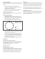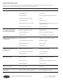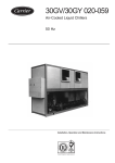
1
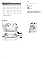
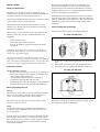
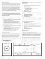
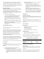
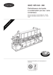
30HT,HQ,HW 043-280
30HZ,HZ"P",HZ"V" 043-280
Liquid chillers and heat pumps
PR
O
C DIA
O L
N O
TR G
O
L
50 Hz
Installation, operation and maintenance instructions
QUALITY ASSURANCE
SYSTEM
1
CONTENTS
Page
Start-up checklist .......................................................................................................................................................................... 3
Dimensions/clearances ................................................................................................................................................................. 4
Technical/electrical data .............................................................................................................................................................. 6
Application data ............................................................................................................................................................................ 8
Maximum chilled water flow ......................................................................................................................................................... 8
Water loop volume ......................................................................................................................................................................... 8
Condenser water flow rates ............................................................................................................................................................ 8
Condenser water flow restrictor ..................................................................................................................................................... 8
Installation ..................................................................................................................................................................................... 9
Safety considerations ...................................................................................................................................................................... 9
Preliminary checks ......................................................................................................................................................................... 9
Moving and siting the unit .............................................................................................................................................................. 9
Check compressor mountings ......................................................................................................................................................... 9
Water connections ...................................................................................................................................................................... 10
Condenser connections ................................................................................................................................................................. 10
Freeze protection .......................................................................................................................................................................... 10
Installation of units with remote condensers ........................................................................................................................... 11
Power supply ............................................................................................................................................................................... 11
Electrical checks ........................................................................................................................................................................... 11
Start-up ........................................................................................................................................................................................ 11
Preliminary checks ....................................................................................................................................................................... 11
Actual start-up .............................................................................................................................................................................. 12
High pressure switch control ........................................................................................................................................................ 12
Servicing refrigeration components .......................................................................................................................................... 12
General maintenance .................................................................................................................................................................... 12
Liquid refrigerant charging ........................................................................................................................................................... 12
Compressors ................................................................................................................................................................................. 13
Heat exchangers ............................................................................................................................................................................ 14
Troubleshooting chart ................................................................................................................................................................ 16
The photo on the front cover is only for illustration purposes and not contractually binding (photo shows unit with optional
compressor sound enclosure).
The manufacturer reserves the right to make modifications at any time without prior notice.
2
START-UP CHECK LIST
Equipment sold by:
Installed by:
Site address:
Equipment type and serial numbers:
Start-up date:
Refrigerant:
Supply voltage:
Phase imbalance:
Ph. 1
V
Ph. 2
V
Ph. 3
V
Current draw:
Ph. 1
A
Ph. 2
A
Ph. 3
A
Main circuit breaker rating:
A
Control circuit voltage:
V
Control circuit fuse:
A
Condenser water entering temperature:
°C
Condenser water leaving temperature:
°C
Cooler water entering temperature:
°C
Cooler chilled water leaving temperature:
°C
Suction pressure:
kPa
Discharge pressure:
kPa
Control thermostat cut-out:
°C
Control thermostat cut-in:
°C
Safety thermostat cut-out:
°C
Low-pressure switch cut-out:
kPa
Low-pressure switch cut-in:
kPa
High-pressure switch cut-out:
kPa
High-pressure switch cut-in:
kPa
Pressure drop through cooler:
kPa
Pressure drop through condenser:
kPa
Oil level:
Oil visible in sight glass:
Colour of moisture indicator:
Air bubbles visible in sight glass:
Commissioning engineer (name):
Purchase order number:
3
Legend:
Dimensions/clearances (mm)
B
C
D
E
F
G
H
J
K
Required clearnces for maintenance
1370
1355
1915
1915
1915
1950
2000
915
915
950
950
950
950
1275
1850
2200
2550
2500
2500
2150
2750
750
750
800
800
800
800
1000
600
600
800
800
800
800
800
600
600
800
800
800
800
1000
600
600
800
800
800
800
800
800
800
850
850
850
850
950
710
710
850
900
900
900
900
Power supply
Units without condenser
043
2252 1110
052-065
2550 1095
091
2630 1300
101-121
2950 1300
141-161
3350 1300
195-225
4255 1340
250-280
4070 1680
905
905
950
950
950
950
1275
1850
2200
2500
2500
2500
2150
2750
750
750
800
800
800
800
1000
600
600
800
800
800
800
800
600
600
800
800
800
800
1000
600
600
800
800
800
800
800
800
800
850
850
850
850
950
710
710
900
900
900
900
900
30H*
A
Units with condenser
043
2252
052-065
2550
091
2630
101-121
2940
141-161
3350
195-225
4255
250-280
4070
Water inlet
Water outlet
*
30H 043 to 280 unit range (see front cover)
NOTE:
Certified dimensional drawings are available on request.
The drawings below are not contractually binding.
All dmensions are given in mm
30H* 043-065
A
Evaporator
C
Condenser (exc. 30HZ"V" and 30HW)
B
H
G
K
D
J
F
E
4
C
With condenser
Without condenser
Sound enclosure
30H* 091-225
Without condenser
B
C
With condenser
Sound enclosure
A
C
Condenser (exc. 30HZ"V" and 30HW)
H
G
K
D
F
J
E
30H* 250-280
B
C
With condenser
Sound enclosure
Without condenser
A
ATTENTION :
2 separate power supplies
C
F
J
H
E
D
K
G
Comp. B4 on 30H 280 only
Floor mounting
-
For unit mounting holes, weight distribution and centre of gravity coordinates, refer to the dimensional drawings
supplied with the unit.
These units are designed for indoor installation.
Ambient temperature:
Max. relative humidity:
5-40°C
50% rh at a temperature of 40°C
5
PHYSICAL DATA
30H*
Net nominal cooling capacity**
Standard chiller 30HT**
30HW condenserless units***
Standard chiller 30HZ**
30HZ“V” condenserless units
Operating weight
30H (with condenser)
30H (without condenser)
Refrigerant charge R407-C****
Circuit A
Circuit B
Refrigerant charge R22****
Circuit A
Circuit B
Compressors
Quantity - Circuit A
Quantity - Circuit B
Control type
No. of capacity steps
Minimum step capacity
Evaporator
Net water volume
No. of refrigerant circuits
Water connections:
Inlet and outlet
Standard
Drain
Max. water side operating pressure
Condenser
Quantity
Water volume
Circuit A
Circuit B
Water connections:
Circuit A
Circuit B
Water box air vent
Water box water drain
Max. water side operating pressure
043
052
065
091
101
111
121
141
161
195
225
250
280
144
136
134
126
166
157
153
144
215
208
199
194
250
234
230
216
292
280
270
260
323
300
230
278
342
321
316
297
402
380
371
351
447
417
415
388
578
538
533
500
677
633
626
588
779
729
719
677
847
792
783
735
1075
863
1165
951
1232
996
2020
1650
2350
1940
2440
1980
2490
2020
2710
2240
2810
2280
3480
2950
3780
3240
4440
3750
4870
4075
15.7
15.7
17.5
17.5
21
21
38.2
19.5
29.5
29.5
34.5
29.5
33.5
33.5
38
38
42
42
54
46.5
54
54
62.5
60.5
62.5
62.5
13.5
14
16.2
33.5
25.5
30
30
13.5
14
15.3
17.5
25.5
25.5
30
Semi-hermetic, 4 or 6 cylinders 24.2 r/s (1450 rpm)
1
1
1
2
2
2
2
1
1
1
1
2
2
2
PRO-DIALOG Plus
4
4
4
8
11
11
11
40
33
33
22
20
18
16
Direct-expansion evaporator, one or two circuits, mult-tube shell
55
63
63
92
154
154
154
2
2
2
2
2
2
2
34
34
40
40
48
43.5
48
50
59
47
59
56
2
2
2
2
3
2
3
3
4
3
4
4
11
19
11
16
5
20
6
16
7
14
8
12
199
2
199
2
242
2
242
2
276
2
276
2
kW
kg
kg
kg
%
l
Dia.
in
kPa
Threaded 3” gas
NFE 03005
1/2” FPT
1000
1000
1000
Shell amd multi-tube type
2
2
2
PN16 DN100 PN16 DN125
NFE 29203
PN16 DN150
1000
1000
1000
1000
1000
1000
1000
1000
1000
1000
2
2
2
2
2
2
2
2
2
2
12
25
12
12
Flat flange, brazed
2”
2” 1/2
2”
2”
18
18
25
18
25
25
25
25
30
30
37
30
37
37
51
37
51
51
2”
2”
2” 1/2
2”
2” 1/2
2” 1/2
3”
2” 1/2
3”
3”
1000
1000
1000
1000
1000
1000
l
in
in
kPa
10
10
10
10
Threaded gas
1” 1/2
1” 1/2
3/8 NPT
3/8 NPT
1000
1000
1000
1000
1000
1000
Legend:
* 30H 043 to 280 unit range (see front cover)
** Net nominal cooling capacity = gross cooling capacity minus the water pump heat against the internal evaporator pressure drop
Nominal Eurovent conditions: evaporator entering/leaving water temperature 12°C and 7°C. Condenser entering/leaving water temperature 30°C and 35°C.
*** Standardised conditions: evaporator entering/leaving water temperature 12°C and 7°C.
Condensing temperature dew point 50°C. Fluid temperature = condensing temperature at dew point - refrigerant glide - 5 K subcooling.
**** The 30H* units have a nitrogen holding charge only.
6
1000
ELECTRICAL DATA
30H*
043
Power wiring
Nominal power supply**
V-ph-Hz
Nominal voltage range
V
Auxiliary circuit
V-ph-Hz
Heater power input 30HT
kW
Heater power input 30HZ
kW
Nominal unit power input
kW
Standard units 30HT
Condenserless units 30HW
Standard units 30HZ
Condenserless units 30HZ“V”
Nominal unit operating current
A
Standard units 30HT
Condenserless units 30HW
Standard units 30HZ
Condenserless units 30HZ“V”
Maximum unit power input***
kW
Standard units 30HT
High condensing pressure/condenserless units
Standard units 30HZ
High condensing pressure/condenserless units
Maximum starting current
A
Standard units 30HT/HZ
Standard units 30HT/HZ, option “PW”
High condensing pressure/condenserless units
High condensing pressure/condenserless units,
option “PW”
Maximum unit operating current***
A
Standard units 30HT
High condensing pressure/condenserless units
Standard units 30HZ
High condensing pressure/condenserless units
052
065
091
101
111
121
141
161
195
225
250
280
400-3-50
360-440
230-1-50
0.25
0.25
0.36
0.36
0.25
0.36
0.38
0.54
0.50
0.72
0.50
0.72
0.50
0.72
0.50
0.72
0.50
0.72
0.63
0.90
0.75
1.08
0.88
1.26
1.00
1.44
34.3
36.9
36.8
37.4
43.4
46.6
46.6
47.3
60
62
64
63
62
67
66
68
69
74
74
75
77
83
85
84
82
90
88
92
99
107
106
109
116
129
124
131
145
158
155
160
175
190
187
193
206
222
221
225
233
252
249
255
57
61
61
62
72
77
77
78
100
103
107
105
102
111
109
112
115
122
123
124
127
137
142
139
136
149
146
152
164
178
176
180
192
214
206
217
240
262
258
266
290
315
311
320
342
368
367
374
386
417
414
423
45
51
42
45
54
62
54
58
75
85
70
76
81
93
75
81
89
103
84
92
98
113
95
103
108
124
102
111
129
147
122
133
151
171
150
158
189
214
180
197
226
256
217
237
264
299
253
272
302
342
286
309
163
std
186
178
std
202
247
std
280
311
222
354
259
202
308
340
251
388
355
266
404
394
305
449
496
373
563
559
437
636
623
501
709
687
565
782
750
628
855
std
std
std
253
239
287
303
348
425
498
571
644
717
73
85
70
75
88
101
90
96
127
146
116
126
132
151
124
134
146
170
139
153
161
185
158
171
176
201
169
184
215
246
202
221
254
291
249
262
318
364
299
327
382
437
360
393
445
510
420
451
509
582
475
513
Legend:
* 30H 043 to 280 unit range (see front cover)
** 30HZ 250-280units have two power points. For separate power supply, please refer to the table below.
*** At maximum unit operating values.
Size
Max. unit power input, kW
Max. unit current drawn, A
Max. starting current, A
30HT Std
30HT“W”+ 30HQ
30HT Std
30HT“W”+ 30HQ
30HT Std
30HT“W”+ 30HQ
Circ. A
Circ. B
Circ. A
Circ. B
Circ. A
Circ. B
Circ. A
Circ. B
Circ. A
Circ. B
Circ. A
Circ. B
250
151
113
171
128
254
191
291
218
496
432
564
491
280
151
151
171
171
254
254
291
291
496
496
564
564
Size
30HZ Std
Circ. A
Circ. B
250
143
280
143
30HZ“V”+ "P"
30HZ Std
Circ. A
Circ. B
Circ. A
Circ. B
110
154
118
237
143
154
154
237
30HZ“V”+ "P"
30HZ Std
30HZ“V”+ "P"
Circ. A
Circ. B
Circ. A
Circ. B
Circ. A
Circ. B
183
256
196
496
432
564
491
237
256
256
496
496
564
564
Note:
All current values are given at nominal voltage.
Electrical data (cont.)
•
•
•
•
30H* units have a single power connection point (except 30H 250-280 which
have two connection points).
The control box includes the following standard features:
Starter and motor protection devices for each compressor
Control devices
Field connections:
All connections to the system and the electrical installations must be in full
accordance with all applicable local codes.
The Carrier 30H chillers are designed and built to ensure conformance with
these codes. The recommendations of European standard EN 60 204-1
(machine safety - electrical machine components - part 1: general regulations)
are specifically taken into account, when designing the electrical equipment.
IMPORTANT:
• Conformance with EN 60 204 is the best means of ensuring compliance with
the Machines Directive § 1.5.1. Generally the recommendations of IEC 364
are accepted as compliance with the requirements of the installation directives.
• Annex B of EN 60204-1 describes the electrical characteristics used for the
operation of the machines.
1. The operating environment for the 30H chillers is specified below:
• Environment* - Environment as classified in IEC 364 § 3:
ambient temperature range: +5°C to +40°C, class AA4*
humidity range (non-condensing)*:
50% relative humidity at 40°C
90% relative humidity at 20°C
altitude: ≤ 2000 m*
indoor installation*
presence of water: class AD2 (possibility of water droplets)*
presence of hard solids, class AE2 (no significant dust present)
presence of corrosive and polluting substances, class AF1 (negligible)
vibration and shock, class AG2, AH2
• Competence of personnel, class BA4* (trained personnel - IEC 364)
2. Power supply frequency variation: ≤ 2 Hz.
3. The neutral (N) line must not be connected directly to the unit (if necessary
use a transformer).
4. Overcurrent protection of the power supply conductors is not provided with the
unit.
5. The factory-installed circuit breaker is of type “a” (EN 60 204-1 § 5.3.2).
NOTE: If particular aspects of an actual installation do not conform to the
conditions described above, or if there are other conditions which should be
considered, always contact your local Carrier representative.
* The required protection level for this class is IP21B (according to reference
document IEC 529). All 30H units are protected to IP23C and fulfill this protection
condition.
7
APPLICATION DATA
Condenser water flow rates
30H*
Passes
Minimum flow rate, l/s**
Closed loop
Open loop
Maximum flow rate, l/s***
Maximum chilled water flow rate
043
052
065
091
101
111
121
141
161
195
225
250
280
2
2
2
2
2
2
2
2
2
2
2
2
2
1.00
1.20
1.40
2.47
2.54
3.04
3.54
3.54
3.54
4.00
4.46
5.04
5.62
12.30
14.40
16.80
29.70
30.60
36.54
42.48
42.48
42.48
48.00
53.64
60.58
67.52
The maximum chilled water flow (>0,09 l/s per kW or <2.8 K
temperature difference) is limited by the maximum permitted
pressure drop in the evaporator.
* 30H 018 to 280 unit range (see front cover)
** Based on a water velocity of 0.3 m/s in closed-loop and 0.9 m/s in open-loop
systems.
***Based on a water velocity of 3.6 m/s.
Minimum cooler water flow rates
30H*
Min flow rate, l/s
043
052-065
091
101-111
141-161
195-280
4.1
5.0
6.0
8.5
9.9
9.9
* 30H 043 to 280 unit range (see front cover)
3.00
3.60
4.20
7.42
7.64
9.13
10.62
10.62
10.62
12.00
13.40
15.14
16.88
Condenser water flow restrictor
Water loop volume
Whatever the size of the system, the water loop minimum
volume is given by the following formula:
CAUTION: To ensure correct operation of the units, this
restrictor must be installed. It is supplied with the machine,
inside the control box.
Volume = CAP (kW) x N* = litres
30H*
No. of passes
OD, mm
Location
043
091
111
195
250
2
2
2
2
2
31
47
47
47
56
Condenser 09RS 022, circuit B - water outlet
Condenser 09RS 054 - water outlet
Condenser 09RS 054 - water outlet
Condenser 09RS 070 - water outlet
Condenser 09RS 084 - water outlet
where CAP is the nominal system capacity (kW) at the nominal
operating conditions of the installation.
Application
N
Air conditioning
Industrial process cooling
Low-ambient temperature
3.25
6.50
6.50
This volume is necessary for stable operation and accurate
temperature control.
It is often necessary to add a buffer water reservoir to the
circuit in order to achieve the required volume. The reservoir
must itself be internally baffled in order to ensure proper mixing
of the liquid (water or brine). Refer to the examples below.
NOTE: The compressor must not restart more than 6 times in
an hour.
8
Bad
Good
Bad
Good
INSTALLATION
Safety considerations
Installation, start-up and servicing this equipment can be
hazardous due to system pressures, electrical components and
equipment location (roofs, elevated structures, etc.).
Only trained, qualified installers and service mechanics should
install, start-up and service this equipment.
Untrained personnel can perform basic functions, such as
cleaning coils. All other operations should be performed by
trained service personnel.
We recommend that these chillers be installed either in a
basement or at ground level. If one is to be installed above
ground level, first check that the permissible floor loading is
adequate and that the floor is strong enough and horizontal. If
necessary, strengthen and level the floor.
30HT/HZ machines require only the connection of condenser
and evaporator water circuits and power and control electrical
supplies. 30HW/HZ'V' units differ only in that they require the
installation of pipework between the chiller and the remote
condensers.
Check compressor mountings
Before the first start-up of the unit proceed as follows:
When working on the equipment, observe precautions in the
literature, and on tags, stickers, and labels attached to the
equipment.
•
•
•
For 30H* 043-065 units
Follow all safety codes.
Wear safety glasses and work gloves.
Use care in handling, rigging and setting down bulky
equipment.
WARNING: Before doing any work ensure that the power
supply (400 V and 230 V) is disconnected, and switches and
isolators are opened and tagged.
During operation some parts of the unit reach or exceed
temperatures of 70°C (e.g. compressor discharge side, discharge
line). Only trained and qualified engineers, aware of these hot
surfaces, are allowed to perform maintenance operations.
Preliminary checks
Check equipment received
•
Inspect the unit for damage or missing parts. If damage is
detected, or if shipment is incomplete, immediately file a
claim with the shipping company.
•
Confirm that the unit received is the one ordered.
Compare the nameplate data with the order.
•
Confirm that all accessories ordered for on-site installation
have been delivered, and are complete and undamaged.
1.
2.
3.
Remove the wooden block located under the compressor
foot.
Remove the screw and washer used for transportation.
Assemble screw (A), snubber (B) and plain washer ( C).
For 30H* 091-280 units
Moving and siting the unit
Moving
Do not remove skids, pallets or protective packaging until the
unit is in its final position. Move the chiller using tubes or
rollers, or lift it, using slings of the correct capacity.
CAUTION: Only use slings at the designated lifting points
which are marked on the unit.
Remove the centre bolt (A) from each spring mounting, so that
the compressor support can float freely.
Siting
Always refer to the chapter 'Dimensions and clearances' to
confirm that there is adequate space for all connections and
service operations.
With the chiller in its final location remove the skids, and other
devices used to aid in moving it. Level the unit using a spirit
level, and bolt the unit to the floor or plinth. Operation of these
units may be impaired if they are not level and not securely
fixed to their mountings.
9
Water connections
Pipe connections
After welding the pipes to the flanges previously removed from
the water boxes:
Refer to the certified dimensional drawings for the sizes and
positions of all water inlet and outlet connections. The water
pipes must not transmit any radial or axial force to the heat
exchangers or any vibration to the pipework or building.
a.
b.
c.
The water supply must be analysed and appropriate filtering,
treatment, control devices, isolation and bleed valves and
circuits built in, as necessary. Consult either a water treatment
specialist or appropriate literature on the subject.
d.
e.
f.
Operating precautions
The water circuit should be designed to have the least number
of elbows and horizontal pipe runs at different levels. Below
the basic checks to be done (see also the illustration of a typical
hydraulic circuit below).
•
•
•
•
•
•
•
•
•
g.
h.
i.
Note the water inlets and outlets of the heat exchangers.
Install manual or automatic air purge valves at all high
points in the water circuit.
Use an expansion chamber or an expansion/relief valve to
maintain pressure in the system.
Install water thermometers in both the entering and
leaving water connections close to the evaporator.
Install drain valves at all low points to allow the whole
circuit to be drained. Connect a stop valve in the drain line
before operating the chiller.
Install stop valves, close to the evaporator, in the entering
and leaving water lines.
Use flexible connections to reduce the transmission of
vibration to the pipework.
Insulate all pipework, after testing for leaks, both to
reduce thermal leaks and to prevent condensation.
Cover the insulation with a vapour barrier.
NOTE: We recommend draining the system and disconnecting
the pipework to ensure that the bolts of the heads to which the
pipework is connected are correctly and uniformly tightened.
If there is a leak outside the water head:
a. Drain the system.
b. Disconnect the water pipes.
c. In the correct sequence, retighten the head bolts to the
maximum torque given for the bolt size.
d. Reconnect the pipework, tightening the bolts to their final
torque value, i.e. the middle value in the range given for
the bolt size.
e. Refill the system with water.
f. Pressurize the system.
Freeze protection
Condenser connections
The condenser is of the multi-tube shell and tube type with
removable water boxes to facilitate cleaning of the tubes.
Cooler and water-cooled condenser protection
If the chiller or the water piping is in an area where the ambient
temperature can fall below 0°C it is recommended to add an
antifreeze solution to protect the unit and the water piping to a
temperatures of 8 K below the lowest anticipated temperature.
Before making water connections tighten the bolts in both
heads to the lower torque shown, following the method
described. Tighten in the pairs and sequence indicated
according to the size of bolt (see below) using a torque value at
the low end of the range given.
Water box tightening
sequence
Reinstall the pipes and tighten lightly to a torque at the
low end of the range.
Fill the system with water.
Wait for 10 minutes and check for minor leaks
at the water box joints
at the flange joints
Drain the system.
Disconnect the pipework.
Tighten the head bolts to their final torque (middle of the
range) in the sequence illustrated.
Reconnect the water pipes, tightening the flange bolts to
the mid-range torque value.
Refill the system with water.
Pressurize the system.
Use only antifreeze solutions, approved for heat exchanger
duty. If the system is not protected by an antifreeze solution
and will not be used during the freezing weather conditions,
draining of the cooler and outdoor piping is recommended.
Typical hydraulic circuit diagram
Air vent
Sequence 1: 1 2 3 4
Sequence 2: 5 6 7 8
Control valve
Flow switch
1
5
7
Heat exchanger
3
4
Flexible connection
8
6
2
Bolt size M12 - 71-87 Nm
Bolt size M16 - 171-210 Nm
Bolt size M20 - 171-210 Nm
Buffer tank
Fill valve
Filter
Expansion tank
10
Pressure tap
Drain
Thermostat sleeve
INSTALLATION OF UNITS WITH REMOTE
CONDENSERS
To ensure optimum and reliable operation of condenserless
units (split units for connection to remote condensers) the
points listed below must be followed, before connection of
these machines to the remote condensers:
WARNING: Operation of the chiller with an improper supply
voltage or with excessive phase imbalance constitutes abuse
which will invalidate the Carrier warranty. If the phase
imbalance exceeds 2% for voltage, or 1% for current, contact
your local electricity supply company at once and ensure that
the chiller is not switched on until corrective measures have
been taken.
1.
Voltage phase imbalance (%) :
2.
3.
4.
5.
6.
7.
Install the valves supplied with the machines on the
discharge line (see unit description table below).
Size the discharge piping in accordance with the
recommendations of the Carrier System Design Manual (if
necessary install a double riser to ensure correct oil
circulation in the refrigerant circuit).
Depending on the actual installation and the routing of the
discharge lines it may be necessary to include an additional
muffler (to reduce pulsations and noise emission) between
the liquid chiller and the condenser. For component
selection contact our customer support team.
Select a condenser with integrated subcooler to obtain an
actual subcooling of at least 3 K at the expansion device
inlet (careful when determining subcooling with R-407C).
Maintain a condensing pressure which is as stable as
possible (pressure switch staging and/or accessory PRODIALOG card). For low-temperature and part-load
operation a speed transformer may be required on the first
fan stage.
If the system can have several operating modes (summer/
winter, dual set point, heat reclaim...), it is necessary to
include a receiver to absorb charge variations.
For units not equipped with a liquid line solenoid valve
(see unit description table below) this type of valve must
be installed between the liquid chiller and the condenser
(closed if no flow is present). This prevents refrigerant
charge migration to the evaporator which could damage
the compressors at the restart.
Power supply
The power supply must conform to the specification on the
chiller nameplate. The supply voltage must be within the range
specified in the electrical data table.
= 100 x max. deviation from average voltage deviation
Average voltage
Electrical checks
WARNING: Never switch off the power supply to the crankcase
heaters unless the chiller is out of service for a seasonal
shutdown or lengthy repair. The heaters must be re-energised
for at least 24 hours before the chiller is restarted.
a.
b.
c.
d.
e.
Switch the unit off.
Open the control circuit disconnect switch.
Check the transformer connections.
Ensure that the control circuit corresponds to the wiring
diagram for the unit.
Check that all electrical connections are secure at the
terminals, contactors, bus bars and compressor terminal
blocks.
Start-up
Preliminary checks
Never be tempted to start the chiller without reading fully, and
understanding, the operating instructions and without having
carried out the following pre-start checks :
Confirm that all crankcase heaters are working by feeling all
compressor crankcases. Every compressor has a 200 W
cartridge heater (see the wiring diagram). The heater remains
energised even when the chiller is shut down to stop the
lubricating oil from absorbing refrigerant.
Check the operation of all accessories - chilled water
circulating pumps, air handlers and other equipment connected
to the evaporator. Follow the individual manufacturer's
instructions for this equipment.
For connections refer to the wiring diagrams.
It is recommended to connect the auxiliary contact of the water
pump contactor to ensure maximum unit safety (see wiring
diagram delivered with the unit).
Unit
Valve
range
Expansion device
Supplied
30HZ"V"/30HW 043-065 Factory-installed in discharge line
Thermostatic
30HZ"V"/30HW 091-280 Supplied with machine, not installed
Electronic
Liquid line solenoid valve
Option
With thermostatic
With electronic
Standard
expansion valve
expansion valve
Electronic
Factory-installed
No solenoid valve
No solenoid valve
2 valves per circuit for sizes 250-280
11
Fill the chilled water circuit with clean water, and an inhibitor
formulated specifically for this purpose, or fill it with another
non-corrosive fluid to be chilled.
Purge air at all high points in the system. If water temperatures
below 5°C are likely, add the appropriate volume of ethylene
glycol to prevent freezing.
Confirm that the suction and discharge line stop valves are
fully opened.
Open the refrigerant line valves. Check again that the water
circuit valves are open.
Check that oil is visible in each compressor sight glass to
between 1/8 and 3/8 of the total glass depth (check for all
compressors).
Confirm that there are no refrigerant leaks.
Confirm that all crankcase heaters are firmly in place, and
check the secure positioning of all control sensors.
Confirm that discharge muffler securing bands and discharge
line connections are tight.
Check that all electrical connections are secure.
Actual start-up
IMPORTANT:
•
Commissioning and start-up of the chiller must be
supervised by a qualified refrigeration engineer.
•
Start-up and operating tests must be carried out with a
thermal load applied and water circulating in the
evaporator.
•
All set point adjustments and control tests must be carried
out before the unit is started up.
•
PLEASE REFER TO THE CONTROLS MANUAL FOR
THE UNIT.
a.
b.
Start up the unit.
Check that all safety devices are satisfied, paticularly the
high pressure switches.
For this purpose:
Stop the condenser water circulation pumps.
Operate the machine until the high pressure switch
trips and verify that the pressure does not exceed the
cut-out value.
Using the control point as a reference, verify the
correct operation of the unit.
High pressure switch control
Unit
Set point (bar)
30HT
30HZ
30HW/HT"W"
30HQ/HZ"W"/HZ"P"
30HZ"V"
19
22
25
25
29
SERVICING REFRIGERATION COMPONENTS
Any technician attending the machine for any purpose must be
a fully qualified refrigeration engineer.
WARNING: Before doing any work on the machine ensure that
the power is switched and locked off and that all isolators are
tagged. If a refrigerant circuit is opened, it must be evacuated,
and recharged, after ensuring that the refrigerant is clean and
free from impurities, the filter-drier has been changed and the
unit has been tested for leaks. Before any operation on a
refrigerant circuit, it is necessary to remove the complete
charge of refrigerant from the unit with a refrigerant charge
recovery group.
General maintenance
Keep the unit itself and the space around it clean and free of
obstructions. Remove all rubbish such as packing materials, as
soon as the installation is completed.
Regularly clean the exposed pipework to remove all dust and
dirt. This makes detection of water leaks easier, and they can
be repaired before more serious faults develop.
Confirm that all screwed and bolted connections and joints are
secure. Secure connections prevent leaks and vibration from
developing.
Check that all insulation joints are securely closed and that all
insulation is firmly in place. Check all heat exchangers and all
pipework.
Confirm regularly that any phase imbalance in the three-phase
power supply is within acceptable limits.
Lubricate the hinges, locks and latches on the electrical control
box doors sparingly.
Liquid refrigerant charging
Checking the charge
WARNING: When adjusting the refrigerant charge always
ensure that water is circulating in the condenser and
evaporator to prevent any possibility of freezing up. Damage
caused by freezing is not covered by the product warranty.
30HT/30HZ units are shipped with a full normal charge of
refrigerant. Refer to the Physical Data table. If it is nevertheless
necessary to add more refrigerant, run the unit at full capacity
for some time and then add refrigerant until there are no
bubbles in the sight glass. This will generally mean adding
more refrigerant than would be needed to prevent bubbles from
being seen in the sight glass.
30HW/30HZV condenserless units are shipped with only a
nitrogen charge, leaving the whole system to be charged after
the installation is complete. To adjust the charge continue
adding liquid refrigerant, with the unit running at full capacity
until there are no bubbles visible in the sight glass.
WARNING: To ensure proper operation of 30HW/30HZ"V" units
there must be at least 3 K of subcooling as the liquid
refrigerant enters the expansion valve.
12
The units 30H* 043-280 use refrigerant. For your information,
we are reproducing here some extracts from the official
publication dealing with the design, installation, operation and
maintenance of air conditioning and refrigera-tion systems and
the training of people involved in these activities, agreed by the
air conditioning and refrigeration industry.
Refrigerant guidelines
Refrigeration installations must be inspected and maintained
regularly and rigorously by specialists. Their activities must be
overseen and checked by properly trained people.
To minimise discharge to the atmosphere, refrigerants and
lubricating oil must be transferred using methods which reduce
leaks and losses to a minimum.
•
Significant undercharge (large bubbles in the sight glass,
drop in suction pressure).
Small units (charge below 20 kg per circuit).
After detection and repair completely drain the
refrigerant charge, using a refrigerant recovery unit,
then recharge completely, following the precautions
given above.
Large units (charge above 20 kg per circuit).
After detection and repair completely recharge the
unit as described above, operate it for a few minutes
and then let a specialist carry out a chromatographic
analysis to verify the composition of the blend (range:
R-32: 22-24%, R-125: 23-27%, R-134a: 50-54%).
Compressors
•
•
•
•
•
Leaks must be repaired immediately
A valve on the condenser liquid refrigerant outlet line
enables the refrigerant charge to be transferred to the
receiver provided specifically for this purpose.
If the residual pressure is too low to make the transfer
alone, a purpose-built refrigerant recovery unit must be
used.
Compressor lubricating oil contains refrigerant. Any oil
drained from a system during maintenance must therefore
be handled and stored accordingly.
Refrigerant under pressure must never be discharged to
the atmosphere.
Recharging liquid refrigerant
CAUTION: 30HZ 043-280 units are charged with liquid
HFC-407C refrigerant.
This non-azeotropic refrigerant blend consists of 23% R-32,
25% of R-125 and 52% R-134a, and is characterised by the fact
that at the time of the change in state the temperature of the
liquid/vapour mixture is not constant, as with azeotropic
refrigerants. All checks must be pressure tests, and the
appropriate pressure/temperature ratio table must be used for
the interpretation of the values.
Leak detection is especially important for units charged with
refrigerant R-407C. Depending on whether the leak occurs in
the liquid or in the vapour phase, the proportion of the different
components in the remaining liquid is not the same.
NOTE: Regularly carry out leak checks and immediately repair
any leak found.
Undercharge
If there is not enough refrigerant in the system, this is indicated
by gas bubbles in the moisture sight glass. There are two
possiblities:
•
Small undercharge (bubbles in the sight glass, no
significant change in suction pressure).
After detection and repair the unit can be recharged.
The replenishment of the charge must always be done
in the liquid phase at the liquid line. The refrigerant
cylinder must contain a minimum of 10% of its initial
charge.
Checking the oil charge
Check the oil level and add or remove oil as necessary so that
the level is 1/8 to 3/8 up each sight glass with the compressors
running normally.
WARNING: Use only oils which have been approved for use in
refrigeration compressors. Never use oil which has been
exposed to air. Oils for R-22 compressors are NOT compatible
with R-407C.
Recommended oil:
30H* R-22 units:
Mineral oil, Carrier specification No. PP 33-2
Suniso 3 GS (Sun Oil Co)
Capella WF 32-150
Clavus G 32 (Shell Oil Co)
Gargoyle Artic (Mobil Oil) - original charge
30HZ R-407Cunits:
Mineral oil, Carrier specification No. PP 47-26
Polyolester Mobil Oil EAL 68
WARNING: All fixing devices and fittings which may have
been removed during servicing must always be replaced upon
completion of the work and before restarting the unit.
Tightening torques to be applied
Description
Diameter, mm
Torque, Nm
Discharge valve
Cylinder head
Suction and liquid line flange
Suction valve
M16
M12
M12
M16
135-140
75-87
75-87
135-140
Compressor motor protection
Circuit breaker
Calibrated, thermo-magnetic, manually reset circuit breakers
protect the compressors against locked rotors and excessive
current draw.
WARNING: Never bypass a circuit breaker or increase its
setting. If a circuit breaker trips, find out why it has done so
and correct the problem before resetting the breaker.
13
Discharge gas thermostat (DGT)
(only for units with low temperature option)
A sensor in each compressor discharge line opens to shut down
the compressor if the discharge gas temperature exceeds the
preset level.
Cut out 146°C
Cut in 113°C
Crankcase heater
Each compressor is fitted with an electric resistance crankcase
heater which prevents any absorption of refrigerant by the
compressor lubricating oil when the compressor is shut down.
Each heater is held in place by a screw clip which must be
secure. Prolonged exposure of the heater to air will result in its
destruction. The heater is energized when the compressor is
switched off.
Plugging evaporator tubes
A leaking tube can be plugged pending replacement. The
number of tubes plugged will determine when they should be
replaced. Check with Carrier the effect upon chiller performance
of plugging a number of tubes. Carrier will need to know the
number of tubes to be plugged and their positions. The figure
below shows the Elliott method of plugging tubes.
WARNING: Take care when inserting plugs not to damage the
plate material between the tubes. Avoid excessive force. Clean
all components with Locquic N and then coat all surfaces with
several drops of Loctite 75 to ensure a good seal without
applying excessive force.
Elliott tube plug
Tube plate
WARNING: Never open or disconnect any switch or circuit
breaker which will cut the supply to the heaters, unless the unit
is to be shut down for lengthy service or repair or for a
seasonal shut down. In all cases the heater must be energised
for at least 24 hours before a compressor is restarted.
Compressor protection circuit board (STARTERGUARD)
Plug
Ring
The purpose of this card is to monitor the compressor
operating environment, in particular:
•
•
•
•
the crankcase heaters
the contactors
the part winding start timer
the control wiring between these components
Heat exchangers
Evaporator
Components
Part number
Tube brass plug
Tube brass ring
---T-853--103500S-*
---T-853--002570S-*
Brass plug (holes without tubes)
Brass ring (holes without tubes)
---T-853--1031—S-*
---T-853--002631S-*
Loctite
Locquic
No. 75*
“N”*
* Order directly from your Carrier distributor
Protection devices
Freeze-up prevention thermostat
The evaporator is protected against loss of water and freeze-up.
The protection is provided by two sensors installed in the
evaporator: one on the entering water side and the other on the
leaving water outlet pipe.
Evaporator maintenance
The evaporator can be removed using the following procedure:
•
•
•
•
Close the chilled water supply and return valves (if
installed), and disconnect the chilled water supply and
return pipe connections.
Drain the water from the cooler.
Remove all temperature sensors from the cooler.
Fold back the insulation at the refrigerant line
connections.
When the evaporator heads and manifolds are removed, the
outer tube end plates will be visible.
Six evaporator tubes are swaged into the end plate and cannot
be removed. A dot punch mark in the end plate opposite each
one identifies each of them. If any of them develop a leak, the
tube must be plugged, as described below.
14
Replacing cooler tubes
Retubing must be done only by a properly trained service
engineer. Most standard practices can be applied, but for cooler
tubes a 5% crush allowance is made for tube expansion and
twisting (15.87 mm diameter tubes are used in these coolers).
The table below gives the specification of the materials used.
Example:
Tube sheet hole diameter
Tube outside diameter
Clearance
Tube inside diameter before rolling
Tube inside diameter after rolling
16.00 mm
15.87 mm
0.13 mm
14.27 mm
14.48 mm
NOTE: Tubes next to the gasket webs must be flush with the
tube sheets at either end of the cooler.
Preparation of gaskets
When rebuilding the cooler, new gaskets must always be used.
They must conform to the Carrier specification for compressed
gaskets.
•
•
•
•
•
Clean the gasket and its place on the tube sheet.
Cover the two matching surfaces (gasket and tube sheet)
with adhesive, and stick them together.
Let the joint dry for 5 minutes.
Moisten the joint with a small amount of compressor oil.
Reinstall the evaporator head within 30 minutes.
Tightening cooler head bolts
Cooler head bolts must be tightened in the specified sequence
and to the correct torque.
Filter-drier
The filter-drier keeps the circuit clean and free of moisture. The
sight glass indicates when it is necessary to change the cartridge
in the filter-drier. A temperature difference between the inlet
and the outlet of the filter-drier indicates fouling of the drier.
NOTE: The unit must run for at least 12 hours before it can
give an accurate indication, because only with the unit running
is the indicator in continuous contact with the refrigerant.
Liquid line service valve
This valve provides, in each circuit, a liquid refrigerant charging
port and, in conjunction with the compressor discharge line
valves, enables liquid refrigerant to be pumped to the high
pressure side of the system.
Use this tightening sequence:
•
Hand tighten the four bolts as shown below in stage 1.
•
Hand tighten the next four bolts as shown below in stage 2.
•
Starting at the 12 o'clock position, and working clockwise,
insert and hand tighten the remaining outer bolts.
•
Insert and tighten the six screws in the center of the head.
7
1
5
4
Bolt size M12 - 71-87 Nm
Bolt size M16 - 171-210 Nm
Bolt size M20 - 171-210 Nm
3
Stage 1
6
2
8
•
•
•
•
Stage 2
Starting again at 12 o'clock and working clockwise tighten
the outer bolts to the correct torque.
Not less than one hour later insert and tighten the six bolts
in the centre of the head, using the torque values given.
After the cooler has been refilled with clean refrigerant,
use a soap and water solution or an electronic detector to
confirm that there are no leaks.
Replace the evaporator insulation and temperature sensors.
Condensers
Precautions for low temperature duty
When 30H* units are likely to experience return chilled water
or brine temperatures of or below 0°C, the condenser water
circulating pumps must continue to run after the last
compressor has shut down.
Refrigerant circuit
Thermal expansion valve (TXV)
The function of the thermal expansion valve is to control the
flow of liquid refrigerant. The valve is controlled by a sensor
bulb in the compressor suction line. It is factory set to maintain
refrigerant superheat of 4 K, based on the dew point. This
setting should not be changed unless absolutely necessary.
15
TROUBLESHOOTING CHART
Below we list a series of possible faults, along with the probable causes and suggested solutions. In the event of a unit
malfunction, it is advisable to disconnect the power supply and ascertain the cause.
SYMPTOMS
CAUSE
REMEDY
Unit does not start
Lack of power supply
Connect power supply
Main switch open
Close switch
Low line voltage
Check voltage and remedy the deficiency
A protection device has tripped
Reset
Contactor stuck open
Replace contactor
Seized compressor or short circuit
Check windings (grounded or short circuit),
replace compressor
Loose electrical connections
Check connections
Defective compressor contactor
Replace contactor
Defective compressor
Check valves, replace compressor
Refrigerant losses
Check and add the necessary charge
Refrigerant losses
Add the necessary refrigerant charge
Low water flow in the evaporator
Check water pump
Blocked expansion valve
Clean or replace
Blocked filter-drier
Replace filter
Defective high pressure switch
Replace pressure switch
Low water flow in the condenser
Check water pump
Blocked condenser
Clean condenser
Piping vibrations
Support piping, check supports and
tightness
Noisy compressor
Check valve plate, change if necessary
Badly fitting panels
Install correctly
Compressor loses oil
Leak in the system
Repair leak
Water losses
Defective inlet or outlet connections
Check and tighten if necessary
Unit operates continually or
starts and stops frequently
Compressor continually cuts out
at low pressure
Compressor continually cuts out
at high pressure
Noises in the system
Order No. 13171-76, March 1998. Supersedes order No.: 13171-76, July 1996.
Manufacturer reserves the right to change any product specifications without notice.
16
Printed on Totally Chlorine-Free Paper.
Printed in the Netherlands.
Manufactured by: Carrier SA, Montluel, France.