1
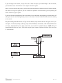
Car★Com Model 400
Car★Com Installation Features
The Automate® Car★Com™ Model 400 can be used in two different ways - either as a stand-alone system to
remotely operate various vehicle functions, or in conjunction with a DEI® security or remote start system to additionally operate the functions of that system.
When used as a stand-alone system, the Car★Com can be configured to lock or unlock the vehicle doors, flash
the parking lights, honk the horn, and disable the starter. The Car★Com can also be used to activate a panic
sequence and an anti-carjacking sequence. Two auxiliary outputs are available for adding accessories such as
remote start or power window operation.
When the Car★Com is used with a compatible DEI® security system, it can additionally be configured to operate
the security system's functions. With this type of installation, the Car★Com can be used to arm and disarm the
DEI security system, activate the Vehicle Recovery System® and Valet® Mode, and initiate Panic Mode. The auxiliary outputs of the DEI® security system can also be operated via the Car★Com. These auxiliary outputs can be
assigned to control optional accessories such as remote start or power window operation.
Plug-In Harnesses
DATA OUTPUT, 3-PIN BLACK PLUG
Use this harness when installing the Model 400 with a compatible DEI security system. Plug one end of the supplied 3-wire harness into the 3-pin data output port of the Car★Com™ and the other end into the data port of
the compatible DEI security or remote start system as shown in the diagram.
© 2001 Directed Electronics, Inc.
1
N400A 3/01
SUPER-BRIGHT STATUS LED, 2-PIN WHITE PLUG
The super bright LED operates at 2V DC. Make sure the LED wires are not shorted to ground as the LED will be
damaged. The LED indicates when a Car★Com™ command has been received. The LED fits into a 9/32-inch mounting hole. When mounting the LED, be sure to check for clearance prior to drilling the mounting hole.
Main Harness (H1), 12-Pin Connector
When using the Model 400 with a compatible DEI system it is not necessary to connect all of the output wires
of the 12-pin main harness; however, the RED (H1/11) power input and BLACK (H1/8) chassis ground input must
be connected.
H1/1
H1/2
H1/3
H1/4
H1/5
H1/6
H1/7
H1/8
______
______
______
______
______
______
______
______
ORANGE
(-) 500 mA ARMED OUTPUT
WHITE
(-) PARKING LIGHT OUTPUT
WHITE/BLUE
(-) 200 mA CHANNEL 3 OUTPUT
BLACK/WHITE
NO FUNCTION
GREEN
NO FUNCTION
BLUE*
DEALER/USER WIRE
VIOLET
NO FUNCTION
BLACK
(-) CHASSIS GROUND INPUT
H1/9 ______
YELLOW
NO FUNCTION
H1/10 ______
BROWN
(-) HORN HONK OUTPUT
H1/11 ______
RED
H1/12 ______
RED/WHITE
(+) CONSTANT POWER INPUT
(-) 200 mA CHANNEL 2 OUTPUT
*NOTE: This wire is not used unless utilizing the Dealer Lot Protection Program.
© 2001 Directed Electronics, Inc.
2
N400A 3/01
Main Harness Wiring Guide
H1/1 ORANGE
This wire provides a latched (-) output when the system locks the doors or the anti-carjacking system is activated. The orange wire can be used to control an optional starter kill relay.
H1/2 WHITE
Connect this wire to the vehicle's (-) parking light circuit.
If the vehicle has a (+) parking light circuit, a relay will need to be added.
© 2001 Directed Electronics, Inc.
3
N400A 3/01
H1/3 WHITE/BLUE AUXILIARY OUTPUT AND H1/12 RED/WHITE AUXILIARY OUTPUT
The auxiliary outputs of the Car★Com™ can be used to operate optional low-current relays or accessories. These
outputs can also be connected to a high current device, such as a motor or a solenoid, but only if a relay has
been added. Connecting a high current device to the auxiliary outputs without adding a relay will damage the
Car★Com™.
H1/4 BLACK/WHITE, H1/5 GREEN, AND H1/7 VIOLET
No function.
H1/6 BLUE
NOTE: This wire is not used unless utilizing the Dealer Lot Protection Program.
This wire controls the Dealer Lot Protection/user mode feature. To utilize Dealer Lot Protection mode, the H1/6
wire must be grounded to an easily accessible ground location in the vehicle. When dealer lot protection mode
is no longer required, remove the H1/6 wire from ground by cutting the wire to select user mode. (For details on
the Dealer Lot Protection Program, contact Directed Electronics at 1-800-876-0800.)
H1/8 BLACK
Connect this wire to bare metal, preferably with a factory bolt rather that your own screw. (Screws tend to either
strip or loosen with time.) Do not confuse this wire with the small gauge black wire that is pre-wired to the
3-pin plug.
H1/9 YELLOW
No function.
© 2001 Directed Electronics, Inc.
4
N400A 3/01
H1/10 BROWN
This wire provides a 200 mA output to drive a low-current factory horn circuit. Connect it to the vehicle's (-)
horn circuit.
If the vehicle has a high current (-) or (+) horn circuit, a relay will need to be added.
H1/11 RED
Connect the red wire to a fused constant 12V source in the vehicle, such as the 12V feed at the ignition switch
or the (+) terminal of the battery. If you are connecting this wire to the (+) terminal of the battery, make sure
to add a fuse and fuse holder as close to the battery as possible. This will protect the vehicle from damage in
case of a short.
H1/12 RED/WHITE
Refer to the H1/3 wire description.
© 2001 Directed Electronics, Inc.
5
N400A 3/01
Internal Jumper
DOUBLE PULSE UNLOCK
SINGLE PULSE UNLOCK
DOUBLE PULSE UNLOCK
To access this internal jumper, open the sliding door on top of the control module. Move the jumper to select
the double pulse unlock feature. Some vehicles require two pulses on the unlock wire to unlock the doors. In
these vehicles, pulsing the unlock wire once will only disarm the factory security system. The doors will unlock
with the second pulse. This will allow installation on vehicles requiring two unlock pulses without adding additional parts.
Secondary Door Lock Harness (H2), (+/-) Door Lock Outputs
H2/A
H2/B
H2/C
______
______
______
GREEN
(-) LOCK, (+) UNLOCK OUTPUT
EMPTY
UNLESS USING 451M
BLUE
(-) UNLOCK, (+) LOCK OUTPUT
This system can control two common power door lock types without any additional parts! With certain vehicles,
or if an actuator is to be installed, either a 451M Door Lock Relay Satellite or two relays will be required.
IMPORTANT! If you mistake a Type C direct-wired system for a Type A positive-pulse system, the
module will be damaged!
TYPE A: (+) 12V PULSES FROM THE SWITCH TO THE FACTORY RELAYS
The system can control a Type A system directly, with no additional parts. The switch will have three wires on
it, and one will test (+)12V constantly. The others will alternately pulse (+)12V when the switch is pressed to
the lock or unlock position.
© 2001 Directed Electronics, Inc.
6
N400A 3/01
If you cannot get to the switch, and you find a set of wires that pulse (+)12V alternately on lock and unlock,
you must take care to ensure that it is not a Type C direct-wire system.
Here is a test: Cut the wire that pulses (+)12V on lock, and then operate the switch to unlock. If all doors unlock,
the vehicle uses a type A system. If you lose all door lock operation in both directions, you are operating the
master switch of a Type C system.
If you lose all door lock operation of one or more doors, but not all motors stop operating, and other doors still
work, you have cut a wire leading directly to one or more motors. You must instead find the actual wires leading
to the switch.
Many domestically-made GM vehicles use Type A locks. However, many more GM vehicles are Type C than in previous years. The full-size pickups (1989-up), many of the S10 Blazers, the Corvette, 1995 Cavalier/Sunfire 1993
and newer, Camaro/Firebird all use Type C door locks, and cannot be controlled without a 451M! Almost all
domestically-built Fords are Type C. Ford builds very few Type A systems. Chrysler builds both Type A and Type
C, so use caution.
© 2001 Directed Electronics, Inc.
7
N400A 3/01
TYPE B: (-) PULSES FROM THE SWITCH TO THE FACTORY RELAYS
This system is common in many Toyota, Nissan, Honda, and Saturn models, as well as Fords with the keylessentry system (some other Fords also use Type B).
The switch will have three wires on it, and one wire will test ground all the time. One wire will pulse (-) when
the switch locks the doors, and the other wire will pulse (-) when the switch unlocks the doors. This type of
system is difficult to mistake for any other type.
TYPE C: REVERSING POLARITY
Interfacing with a reversing polarity system requires either two relays or one 451M (not included).
It is critical to identify the proper wires and locate the master switch to interface properly. Locate wires that
show voltage on lock and unlock. Cut one of the suspect wires and check operation of the locks from both
switches. If one switch loses operation in both directions and the other switch operates in one direction only,
you have located one of the target wires. The switch that lost all operation is the master switch. If one switch
works in both directions and the other switch works in only one direction, you have a Type A system. If both
switches still operate, but one or more doors have stopped responding entirely, you have cut a motor lead. Reconnect it and continue to test for another wire. Once both wires have been located and the master switch is
identified, cut both wires and interface as shown in the following diagram.
IMPORTANT! If these are not connected properly, you will send (+) 12 volts directly to (-) ground,
possibly damaging the alarm or the factory switch.
© 2001 Directed Electronics, Inc.
8
N400A 5/99
TYPE D: AFTER-MARKET ACTUATORS
In order for this system to control one or more after-market actuators, a 451M or two relays (optional) are
needed.
Vehicles without factory power door locks require the installation of one actuator per door. This requires
mounting the door lock actuator inside the door. Other vehicles may only require that one actuator be installed
in the driver's door if all door locks are operated when the driver's lock is used. This type of installation is
required to operate factory lock systems in Volvo (except 850), SAAB, and most Mazda, Isuzu and Subaru models.
The fuse used on 12-volt inputs should be 7.5A per motor installed in the vehicle.
© 2001 Directed Electronics, Inc.
9
N400A 3/01
TYPE F: ONE-WIRE SYSTEM
This system usually requires a negative pulse to unlock, and cutting the wire to lock the door. In some vehicles,
these are reversed. It is found in late-model Nissan Sentras, some Nissan 240SX, and Nissan 300ZX 1992-up. It
is also found in some Mazda MPV's and some Mitsubishi's.
One relay (optional) is used to interface to this type of system as follows:
TYPE G: POSITIVE MULTIPLEX
This system is most commonly found in Ford, Mazda, Chrysler and GM vehicles. The door lock switch or door key
cylinder may contain either one or two resistors. When interfacing with this type of door lock system, two relays
or a DEI 451M must be used.
© 2001 Directed Electronics, Inc.
10
N400A 3/01
Single-Resistor Type
If one resistor is used in the door lock switch/key cylinder, the wire will pulse (+)12V in one direction and less
than (+)12V when operated in the opposite direction.
Two-Resistor Type
If two resistors are used in the factory door lock switch/key cylinder, the switch/key cylinder will read less than
(+)12V in both directions.
Determining the Proper Resistor Values
To determine the resistor values, the door lock switch/key cylinder must be isolated from the factory door lock
system. For all testing, use a calibrated digital multimeter that is set to ohms.
1. Cut the output wire from the door lock switch/key cylinder in half.
2. Test with the meter from the switch side of the cut door lock switch/key cylinder wire to a reliable constant
(+)12V source. Some good constant (+)12V references are the power input source to the door lock switch/key
cylinder, the ignition switch power wire, or the (+) terminal of the battery.
3. Operate the door lock switch/key cylinder in both directions to determine the resistor values. If the multimeter displays zero resistance in one direction, no resistor is needed for that direction.
4. Once the resistor value(s) is determined, refer to the wiring diagram for proper wiring.
TYPE H: NEGATIVE MULTIPLEX
The system is most commonly found in Ford, Mazda, Chrysler and GM vehicles. The door lock switch or door key
cylinder may contain either one or two resistors. When interfacing with this type of door lock system, two relays
or a DEI 451M must be used.
© 2001 Directed Electronics, Inc.
11
N400A 3/01
Single-Resistor Type
If one resistor is used in the door lock switch/key cylinder, the wire will pulse ground in one direction and resistance to ground when operated in the opposite direction.
Two-Resistor Type
If two resistors are used in the factory door lock switch/key cylinder, the door lock switch/key cylinder will read
resistance to ground in both directions.
Determining the Proper Resistor Values
To determine the resistor values, the door lock switch/key cylinder must be isolated from the factory door lock
system. For all testing, use a calibrated digital multimeter that is set to ohms.
1. Cut the output wire from the door lock switch/key cylinder in half.
2. Test with the meter from the switch side of the cut door lock switch/key cylinder wire to a reliable ground
source. Some good ground references are the ground input source to the door lock switch/key cylinder or the
battery ground.
3. Operate the door lock switch/key cylinder in both directions to determine the resistor values. If the multimeter displays zero resistance in one direction, no resistor is needed for that direction.
4. Once the resistor value(s) is determined, refer to the wiring diagram for proper wiring.
Testing the Car★Com System
The following procedure will work for testing the Car★Com, whether it has been installed as a stand-alone system
or if it has been installed with a DEI® compatible system:
From a touch-tone phone:
1. Call toll-free 866-SKYALERT, (866)-759-2537, or (619) 528-0100 from a pay phone.
2. Enter the Car★Com PIN code.
3. Enter the test security code: 7832. This code will work for 24 hours for testing purposes.
4. Test all functions of the unit. Refer to the Automate Car★Com Model 400 Owner's Guide for operating
instructions.
© 2001 Directed Electronics, Inc.
12
N400A 3/01