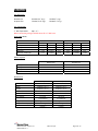
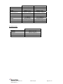
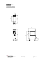
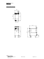
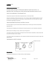
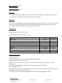
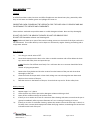
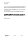
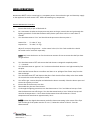
1
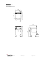
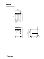
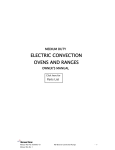
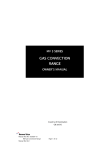
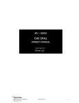
MV 2 SERIES
GAS FRYER
OWNER’S MANUAL
Country of Destination
GB and IE
Manual Part No: 932973-01
Manual Rev No: 1
MD Gas Fryer
Page 1 of 30
Model No.
Product Description
Rev.
Date
Flexible
Hose Size
MV Gas Fryers
MV2FST30-NG
300 Fryer with Stainless Tank
1
20/05/08
¾” BSP hose
MV2FST30-LP
300 Fryer with Stainless Tank
1
20/05/08
¾”BSP hose
MV2FST30-NG-C
300 Fryer with Stainless Tank
1
20/05/08
¾”BSP hose
MV2FST30-LP-C
300 Fryer with Stainless Tank
1
20/05/08
¾”BSP hose
MV2FST45-NG
450 Fryer with Stainless Tank
1
20/05/08
¾” BSP hose
MV2FST45-LP
450 Fryer with Stainless Tank
1
20/05/08
¾”BSP hose
MV2FST45-NG-C
450 Fryer with Stainless Tank
1
20/05/08
¾” BSP hose
MV2FST45-LP-C
450 Fryer with Stainless Tank
1
20/05/08
¾”BSP hose
MV2FST60-NG
600 Fryer with Stainless Tank
1
20/05/08
¾” BSP hose
MV2FST60-LP
600 Fryer with Stainless Tank
1
20/05/08
¾” BSP hose
MV2FST60-NG-C
600 Fryer with Stainless Tank
1
20/05/08
¾” BSP hose
MV2FST60-LP-C
600 Fryer with Stainless Tank
1
20/05/08
¾”BSP hose
MV2FTT60-NG
600 Fryer Twin Tank with Stainless Tank
1
20/05/08
¾” BSP hose
MV2FTT60-LP
600 Fryer Twin Tank with Stainless Tank
1
20/05/08
¾” BSP hose
MV2FTT60-NG-C
600 Fryer Twin Tank with Stainless Tank
1
20/05/08
¾” BSP hose
MV2FTT60-LP-C
600 Fryer Twin Tank with Stainless Tank
1
20/05/08
¾”BSP hose
Manual Part No: 932973-01
Manual Rev No: 1
MD Gas Fryer
Page 2 of 30
INDEX
Page
Cover Sheet:
1
Revision Sheet:
2
Index:
3
Introduction:
4&5
General Introduction
4
Important Note
5
Specification:
6 - 11
Gas Pressure / Connection
6
Overall Dimensions
8 - 11
Installation:
12 - 14
Important Note
12
Positioning
12
Checking & Commissioning
13 & 14
User’s Instruction:
15 – 20
Important Note
15
Operation
16 & 17
Cooking Guide
18
Cleaning
19 & 20
Service & Maintenance:
21 - 27
Routine Maintenance
21 - 22
Fault Finding
23
Wiring Diagram
24
Instructions
25 - 27
Spare Parts:
28 & 29
Warranty Cover Sheet:
30
Manual Part No: 932973-01
Manual Rev No: 1
MD Gas Fryer
Page 3 of 30
INTRODUCTION
This manual contains all the required information to ensure that your new appliance is installed correctly
and that you have all the information necessary to identify and order spare parts. It also contains
comprehensive instructions for the user and for cleaning the appliance.
To maintain peak performance, it is recommended that the appliance be regularly serviced and that
when ordering spare parts, reference be made to the appropriate list quoting the Part No. and the
description therein. THE FITTING OF A NON-STANDARD PART MAY VOID ANY GUARANTEE.
All work carried out on this appliance during installation or servicing must be performed by a competent
person and the connection of the appliance to the gas supply MUST be carried out by qualified
personnel in accordance, where applicable, with the relevant regulations.
The siting of the appliance and the connection to the gas supply must comply with the latest GAS
SAFETY (INSTALLATION & USE) REGULATIONS 2000: the requirements of the FIRE PRECAUTIONS ACT
1971; the HEALTH & SAFETY AT WORK, ETC ACT 1974, the BUILDING STANDARDS (SCOTLAND)
CONSOLIDATION REGULATIONS 1971. Detailed recommendations are contained in British Standards
BS5440 Part 1:2000, BS5440: Part 2:2000, BS5588: Part 0:1996, BS5588: Part 11:1997 & BS6173: 2001.
An easily accessible stopcock must be fitted in the gas supply adjacent to the appliance for use in
emergency.
The details of the gas supply will be found on the Data Plate, which is located on the rear of the flue
upstand/splashback panel.
Improvements
The policy of Viscount Catering Ltd is such that, each product is subject to continual development and
may, therefore, be subsequently improved. The company reserves the right to alter the design of any
appliance without prior notification and without the responsibility to update any delivered or in-service
appliance and furthermore, without incurring the responsibility for altering these instructions. In such
circumstances, it may be found that the appliance detailed herein differs in certain respects from the one
supplied.
IT IS IMPORTANT, THEREFORE, TO QUOTE THE SERIAL No. AND THE APPLIANCE MODEL No. IN ALL
COMMUNICATIONS WITH THE COMPANY.
Manual Part No: 932973-01
Manual Rev No: 1
MD Gas Fryer
Page 4 of 30
Introduction (cont.)
Important
Before installing any item please refer to the installation instructions.
We recommend that all servicing other than routine cleaning be carried out by our authorised service
agents and will accept no responsibility for work carried out by other persons.
For satisfactory operation, parts of catering equipment become hot. Suitable precautions must be taken
to avoid accidental burns therefore the appliance should be positioned to minimise the possibility of
accidental touching. It is the supervisors’ responsibility to warn users to wear suitable protection and to
follow correct operation and cleaning procedures.
For the details of your nearest Service Agent for all warranty and repair work, you should contact: -
The Service Department,
Enodis UK Food Service Group
Enodis House
5E Langley Business Centre
Station Road
Langley
Berkshire
SL3 8DS
Tel: +44 (0) 1753 485902
Fax:+44 (0) 845 301 1461
Spares can be obtained via the Spare Parts Department at the above address.
IT IS IMPORTANT, TO QUOTE THE SERIAL No. AND THE APPLIANCE MODEL No. IN ALL
COMMUNICATIONS WITH THE COMPANY.
Manual Part No: 932973-01
Manual Rev No: 1
MD Gas Fryer
Page 5 of 30
SPECIFICATION
Gas Pressures
Natural Gas
20mbar(8.0” w.g.)
15mbar(6” w.g.)
Propane Gas
37mbar(14.8” w.g.)
37mbar(14” w.g.)
Gas Connection
½” BSP Taper Male
(Rp 1/2”)
When connecting using a flexible hose fit a ¾” BSP hose
Heat Input (Nett)
Natural Gas
Propane Gas
m3/hr
Btu/hr
kW
kg/hr
Btu/hr
kW
300 Fryer
1.4075
45,379
13.3
1.065
46,403
13.6
450 Fryer
2.87
92,806
27.2
1.84
80,182
23.5
600 Fryer
3.48
115,871
33.1
2.52
109,866
32.2
600 Twin Tank Fryer
3.55
114,643
33.6
2.57
112,050
32.84
Burner Injector
Natural Gas
Propane Gas
300 Fryer
2.15mm
135mm
450 Fryer
3.03mm
1.84mm
600 Fryer
3.42mm
2.10mm
600 Twin Tank Fryer
2.36mm
1.50mm
Dimensions
300 Fryer
450 Fryer
300mm ( 11.8”)
450mm ( 17.7”)
Depth
700mm ( 27.5”)
700mm ( 27.5”)
Height
950mm ( 37.4”)
950mm ( 37.4”)
230mm x 480mm
310mm x 480mm
2 x ( 9” x 18.8”)
(12.2” x 18.8”)
Width
Pan Area (W x D)
Oil Capacity
Weight
Output of raw chips/hr
Manual Part No: 932973-01
Manual Rev No: 1
17 Litres
20 Litres
(3.8 Gallons)
(4.4 Gallons)
55 kg (121 lbs.)
70 kg (154 lbs.)
22.7 kg
34 kg
(50 lbs.)
(74 lbs.)
MD Gas Fryer
Page 6 of 30
600 Fryer
600 Twin Tank Fryer
Width
600mm ( 23.6”)
600mm ( 23.6”)
Depth
700mm ( 27.5”)
700mm ( 27.5”)
Height
950mm ( 37.4”)
950mm ( 37.4”)
460mm x 480mm
2 x 230mm x 480mm
(18.1” x 18.8”)
2 x (9” x 18.8”)
23 Litres
2 x 17 Litres
(5.1 Gallons)
2 x (3.8 Gallons)
85 kg (187 lbs.)
85 kg (187 lbs.)
45.4 kg
2 x 22.7 kg
(100 lbs.)
2 x (50 lbs.)
Pan Area (W x D)
Oil Capacity
Weight
Output of raw chips/hr
Air Requirements
Area
300 Fryer
74
cm2
(11.5 in2)
450 Fryer
120 cm2 (18.5 in2)
600 Fryer
150 cm2 (23.2 in2)
600 Twin Tank Fryer
148 cm2 (23.0 in2)
Manual Part No: 932973-01
Manual Rev No: 1
MD Gas Fryer
Page 7 of 30
Specification (cont.)
300mm Single Tank Fryer
300
62
774
480
G
234
900
1058
710
150
228
G
Manual Part No: 932973-01
Manual Rev No: 1
MD Gas Fryer
Page 8 of 30
Specification (cont.)
450mm Single Tank Fryer
450
62
774
480
G
312
900
1058
710
150
228
G
Manual Part No: 932973-01
Manual Rev No: 1
MD Gas Fryer
Page 9 of 30
Specification (cont.)
600mm Single Tank Fryer
600
62
774
480
G
462
900
1058
710
150
228
G
Manual Part No: 932973-01
Manual Rev No: 1
MD Gas Fryer
Page 10 of 30
Specification (cont.)
600mm Twin Tank Fryer
600
62
774
483
G
234
900
1058
710
150
228
G
Manual Part No: 932973-01
Manual Rev No: 1
MD Gas Fryer
Page 11 of 30
INSTALLATION
Important
Your attention is drawn to the latest GAS SAFETY (INSTALLATION & USE) REGULATIONS 2000.
This appliance MUST be installed by a competent person in accordance with these and any other relevant
regulations. Users, too, should be aware of the regulations governing the use of gas appliances,
particularly with respect to the need for regular servicing.
Your attention is drawn to the requirement that those parts, which have been protected by the
manufacturer or his agent, are not to be adjusted by the installer.
Before Installation
Before commencing installation, remove all packaging materials from the appliance. It is suggested that
any protective film adhering to the stainless steel panels should be left on until installation is completed.
BUT THIS MUST BE REMOVED BEFORE COMMISSIONING OR OPERATING THE APPLIANCE.
Check the appliance Data Plate (located on the back of the flue upstand/splashback panel), to ensure
that the appliance is suitable for the gas supply available.
Ensure that the floor upon which the appliance is to stand is level and capable of adequately supporting
the weight of the appliance. TO COMPENSATE FOR SOME UNEVENNESS OF THE FLOOR, THE
APPLIANCE FEET ARE ADJUSTABLE.
THE FLOOR MUST BE FIRE PROOF. If it is not, or if any adjacent wall or surface is made of a combustible
material, then the installer MUST ensure that the requirements of the LOCAL FIRE REGULATIONS are
observed.
Positioning
In order for us to meet the stability requirements, this fryer MUST BE FIXED TO THE FLOOR by means of
the fixing holes in the flanged feet. This is not necessary if the fryer is in a suite and therefore fixed to
another appliance.
Place the appliance in position allowing a minimum gap of 150mm (6”) at the rear and at least 150 mm
(6”) between the sides of the appliance and any adjacent wall. The minimum distance between the top of
the appliance and any overshelf or ceiling constructed of a combustible material must be 1525 mm
(60”).
Adequate ventilation is essential for safe operation of a gas appliance. A supply of fresh air is necessary
for the correct combustion of the gas and there must be a means of exhausting the heat and the
products of combustion from the kitchen. It is recommended that the appliance be sited below a
ventilating hood, one preferably connected to an extractor system incorporating a grease filter.
Manual Part No: 932973-01
Manual Rev No: 1
MD Gas Fryer
Page 12 of 30
Installation (cont.)
Important Note
These appliances are to be installed with sufficient ventilation to prevent the occurrence of unacceptable
concentrations of substances harmful to health in the room in which they are installed.
The appliance MUST NOT be connected DIRECTLY to a flue or ventilating system, although the flue
products of two or more appliances may be directed into a common outlet when building a suite of
appliances (see separate instructions for suiting appliances).
Ensure that the appliance is level in two places - front to rear and side to side. To check the level it is
recommended that a spirit level be placed on the top of the unit. Level can be achieved by adjusting any
or all of the screw in feet in each corner of the base. Turn anti-clockwise to lower and clockwise to raise
the corner. Warning if the appliance is to be free standing it should be screwed to the floor through the
two front legs to ensure stability.
Gas Connection
Natural Gas: The size of the supply pipe should be no smaller than ½” BSP and an easily accessible
stopcock must be fitted in the gas line adjacent to the appliance.
An armoured flexible pipe of a GAS COUNCIL APPROVED PATTERN is recommended.
NOTE:
Due to the pressure loss through the snap connection fitting on flex hoses you must fit a ¾”
flexible hose to all 600mm wide Twin Basket Fryers
Ensure that all the pipes to the appliance are clean and free from swarf etc, BEFORE making the final
connection.
Propane Gas: Follow the same procedure as that for Natural Gas EXCEPT that the Gas Governor MUST BE
DISSABLED using the Governor exclusion screw, - the Gas Supply Tank or Cylinders are already fitted
with a Gas Regulator.
Leak Test
Clean off any protective film from the stainless steel panels.
AT THIS STAGE, LEAK TEST THE WHOLE SYSTEM. THE GAS SAFETY REGULATIONS require that ALL
connections in the gas supply line between the Gas Meter and the appliance is tested for gas leaks.
THIS MUST BE DONE BEFORE COMMENCING TO COMMISSION THE APPLIANCE.
Manual Part No: 932973-01
Manual Rev No: 1
MD Gas Fryer
Page 13 of 30
Installation (cont.)
Checking and Commissioning (cont.)
ALTHOUGH EVERY APPLIANCE IS TESTED AND SET BEFORE IT LEAVES THE FACTORY, IT IS
IMPORTANT THAT THE INSTALLER RE-CHECKS CERTAIN FUNCTIONS BEFORE LEAVING THE SITE.
CHECK THE GAS PRESSURE AT THE APPLIANCE THUS: The pressure test point is behind the compartment door on the Control Valve.
Connect a manometer (U tube) to the test point. Turn on the gas supply and light the appliance. Check
that the pressure reading agrees with that stated on the Data Plate (for Twin Tank models this should
be carried out separately for each tank).
SHOULD ADJUSTMENT BE NECESSARY, PROCEED AS FOLLOWS: On the gas governor: (part of Control Valve). Remove the cap in order to gain access to the pressure
adjusting screw.
Turn the pressure adjusting screw clockwise to increase the pressure or anti-clockwise to decrease it.
When the pressure reading is correct, refit the cap to the governor.
Turn the gas supply to the unit OFF at the stopcock and disconnect the manometer (U tube). Ensure that
the pressure test point screw is refitted.
Turn the gas supply to the appliance on at the stopcock and leak test the pressure test point using a leak
detection fluid.
FOR PROPANE GAS, REFER TO SUPPLIER.
PRESSURE TEST POINTS
TP TH TP
GOVENOR ADJUSTMENT
SCREW
OUT IN
TH
PILOT
Burner Aeration
The aeration of all the burners is fixed and does not need adjusting.
Manual Part No: 932973-01
Manual Rev No: 1
MD Gas Fryer
Page 14 of 30
USERS INSTRUCTIONS
Important Note!
The attention of the user is drawn to the requirements of the GAS SAFETY (INSTALLATION & USE)
REGULATIONS 2000. This appliance MUST be used in accordance with those, particularly so in respect
of the need for regular servicing.
The attention of the user is also drawn to the requirement that those parts, which have been protected
by the manufacturer or his agent, are not to be adjusted by the user.
If it is necessary to remove the fryer ensure all the oil has been drained prior to moving. See also the
sections of this manual referring to Cleaning and General Maintenance.
Safety Note
This appliance is intended for professional use and shall only be used by qualified personnel.
Parts and surfaces of this appliance get hot in use. It is the responsibility of the kitchen supervisor to
inform and warn every user and kitchen worker of this and, furthermore, to ensure those users wear and
use protective clothing when operating the appliance.
Should any adjustment or attention be necessary, you are advised to contact your nearest CORGI
(Confederation for the Registration of Gas Installers) Service Engineer immediately. The need for regular
servicing is detailed in the GAS SAFETY (INSTALLATION & USE) REGULATIONS 2000.
IF YOU THINK THAT GAS IS ESCAPING, ACT IMMEDIATELY. SHUT OFF THE GAS SUPPLY AT THE
METER OR EMERGENCY CONTROL; CONTACT THE SUPPLIER OF YOUR GAS IMMEDIATELY.
MAKE SURE THAT ALL USERS OF THIS APPLIANCE KNOW WHERE THE GAS SUPPLY STOPCOCK IS
LOCATED FOR THE USE IN AN EMERGENCY.
Improvements
The policy of Viscount Catering Ltd is such that each product is subject to continual improvement. The
company reserves the right to alter the design of any appliance without prior notification and without the
responsibility to update any delivered or in-service appliance and, furthermore, without incurring the
responsibility for altering these instructions. In such circumstances, it may be found that the appliance
detailed herein differs in certain respect from the one supplied.
For further details or enquires please contact:
Enodis Uk Food Service Group
Enodis House, 5E Langley Business Centre, Station Road, Langley, Berkshire, SL3 8DS
Tel: +44 (0) 1753 485900
Fax: +44 (0) 1753 485901
Manual Part No: 932973-01
Manual Rev No: 1
MD Gas Fryer
Page 15 of 30
Users Instructions (cont.)
Lighting Instructions
WARNING: DO NOT LIGHT THE BURNERS WHEN THE PAN IS EMPTY.
1)
Open the compartment door; ensure that the drain valve is fully closed (turn clockwise) and the
locking chain is engaged. Check that the cooking oil is up to the level marked at the back of the
pan.
The oil required to fill the pan to the level is:
300 Fryer
17 Litres (3.8 gallons
450 Fryer
20 litres (4.4 gallons)
600 Fryer
23 litres (5.1 gallons)
600 Twin Tank Fryer
2 x 17 litres (3.8 gallons)
2)
Turn on the gas supply.
3)
Turn the thermostat knob to the OFF position.
4)
Turn the control valve knob anti-clockwise to the Pilot positionΣ, push and hold-in, and press
piezo igniter.
5)
Hold knob depressed for a further 30 seconds to establish flame, release and check that the
6)
If the burner is extinguished on releasing knob, repeat steps 4 & 5.
7)
Turn the control knob anti-clockwise to the ON position.
burner remains alight.
8)
Turn the thermostat knob to the required setting to light the main burners, checking that they
light before closing the door.
If the pilot goes out for any reason, turn the control valve knob to the OFF position n and wait 3
minutes before re-lighting. This will allow the valves integral safety device to re-set. Under no
circumstances should this valve knob be forced.
NOTE: - When first lighting the appliance after installation or after an extended shut-down period, it
may be necessary for the control knob to remain pushed-in for some time before the burner will light,
owing to the presence of air in the gas line.
To Turn Off
1)
For short periods, turn the thermostat knob to the OFF positionn.
This will leave the pilot burner alight and the fryer ready for use.
2)
For longer periods, (or if the fryer is to be left UNATTENDED), turn the thermostat to the OFF
positionn, turn the control valve to the OFF positionn, and close external stopcock.
Manual Part No: 932973-01
Manual Rev No: 1
MD Gas Fryer
Page 16 of 30
Users Instructions (cont.)
Use of Solidified Oil or Fat
1)
In an Empty Pan.
IMPORTANT: If solidified oil or fat is to be used, remove the grid from the bottom of the pan,
break the solidified oil or fat into small pieces and fill the V shaped bottom of the pan.
Light the appliance and turn the thermostat knob to 130° C. Continue to add pieces of fat into
the pan until the V shaped bottom is filled with the molten fat. If the fat appears to be
overheating, turn the thermostat OFF, continue to add fat and turn the thermostat ON when the
fat has cooled.
Refit the grid and put the remaining pieces of oil or fat into the pan until the level is up to the
mark. Allow to heat up slowly until all the fat has melted, and then turn the thermostat knob to
the required cooking temperature.
2)
Already Solidified In the Pan.
Light the appliance and turn the thermostat ON for approximately 5 - 10 seconds and then turn
OFF again. Leave it for 30 seconds before repeating the 5 - 10 seconds cycle.
Continue to repeat until the fat has melted so that any remaining un-melted pieces are free
floating, and then turn the thermostat to the required temperature.
Cooking Instructions
With the thermostat knob turned to the required cooking temperature, allow the oil or fat to heat up for
about 20 minutes before starting to cook. After each load is removed from the fryer always allow 2 ½
minutes for the temperature of the oil to recover before the next load is put into the oil.
The Frying Medium
Ensure oil is always maintained at the correct level indicated and neither under or over-filled.
The attention of the user is also drawn to the risks due to replenishment of the oil when the fryer is hot.
Good quality vegetable oil is recommended.
The life expectancy of oils will be lengthened if they are filtered regularly - food particles not removed turn
rancid and reduce oil quality. The life of the oil will also be extended if the temperature is turned down
when the fryer is not in use.
“Please note also, using old oil will reduce the flash point and therefore present a greater fire hazard and
be more prone to surge boiling. Attention shall also be drawn to the effect of over-wet food and too
large a charge on surge boiling”. Hot oil is dangerous; it must not be handled until it has cooled to a safe
temperature.
Manual Part No: 932973-01
Manual Rev No: 1
MD Gas Fryer
Page 17 of 30
Users Instructions (cont.)
Cooking Instructions (cont.)
Chip Frying
The recommended load for each batch is 2 ¼ kg (5 lbs.) for each basket. This will fill the basket about
2/3 rd full and it is important that this load should not be exceeded.
Fish Frying
Cook fish by free floating them. Seven or eight 100g pieces in the 300 Fryer or 12 - 14 pieces in the 600
Fryer may be cooked at one time. Slide the fish into the pan slowly to avoid splashing of the oil or fat
and to prevent the fish sinking and sticking to the base of the pan.
Cooking Chart
The following chart is for guidance only.
Maximum basket load not to exceed 2 1/4kg.
Food
Time
Temperature
5 – 8 minutes
175° C
Chipped Potatoes (Blanched)
3 minutes
165° C
Chipped Potatoes (Browning)
1 - 2 minutes
190° C
Chipped Potatoes (Raw)
4 – 5 minutes
190° C
Doughnuts
3 – 4 minutes
170° C
Fish Fillets
5 – 7 minutes
175° C
Fritters
3 – 4 minutes
175° C
2 minutes
190° C
3 – 4 minutes
175° C
Chicken Pieces
Potato Crisps
Scampi
To Obtain Best Results
Keep the pan clean.
Use good quality oil or fat, which has high breakdown temperature.
Use only clean oil or fat and strain daily.
Maintain the oil or fat at the correct level. Do not start to fry until the oil has reached the correct
temperature.
Do not exceed the temperature of the oil or fat as recommended by the supplier.
Do not overload the fryer.
Remove the crumbs or pieces floating on the surface of the oil. When using frozen foods follow the food
manufacturers cooking instructions carefully.
To conserve energy, turn the thermostat knob to the OFF position during breaks in frying.
Manual Part No: 932973-01
Manual Rev No: 1
MD Gas Fryer
Page 18 of 30
Users Instructions (cont.)
Cleaning
It will be found that it takes less time and effort if appliances are cleaned every day, particularly while
they are still warm and before grease and spillages are burnt on.
PROPRIETARY OVEN CLEANER MUST BE USED WITH CARE; THEY ARE HIGHLY CORROSIVE AND MAY
CAUSE DAMAGE TO SURFACES AND COMPONENTS.
Clean stainless steel with soap and hot water or a mild detergent solution. Rinse and dry thoroughly.
DO NOT USE CAUSTIC OR ABRASIVE CLEANERS, DO NOT USE ABRASIVE PADS.
DO NOT USE flammable solvents and cleaning aids
NOTE! Carbon will build up as part of the natural cooking process on the inside of the Fryer tank and is
not detrimental. The carbon build up can be kept to a minimum by regular cleaning and boiling with a
soapy water solution.
Daily Cleaning
1)
2)
Turn the gas control valve to OFF.
Screw the drainpipe into the drain valve. Place a suitable container with a filter below the drain
tap, remove the safety chain and open the tap.
NOTE: The oil or fat will flow more freely if it is still warm but on no account should the fat be
filtered at frying temperatures.
3)
Remove the frying basket and also the strainer from the bottom of the pan and clean these
4)
Clean the inside of the pan with a clean cloth, taking care not to damage the two thermostat
thoroughly at the sink.
phials in the V section of the pan.
5)
Refit the strainer in the bottom of the pan, close the drain tap and re-fit the safety chain.
Weekly Cleaning
6)
Repeat stages 1 to 3 above.
7)
Close the drain tap, fill the pan with a detergent solution and bring to boil.
8)
Drain off the solution and wipe all surfaces clean.
9)
If the fryer is to remain out of use for some time after cleaning with water, ensure that the pan is
greased immediately after to prevent formation of rust. A coating of cooking oil is best.
10)
If the fryer is to be re-used after cleaning, replace the strainer. Ensure the drain tap is closed, refit safety chain, remove the drainpipe and renew the frying medium, maintaining the correct level
indicated on the back of the pan.
Manual Part No: 932973-01
Manual Rev No: 1
MD Gas Fryer
Page 19 of 30
Users Instructions (cont.)
General Maintenance and Care
This equipment is designed and manufactured to give you long, satisfactory service at low cost, provided
that it is given proper care and attention at all times. Frequent cleaning and regular checking of correct
adjustments will be rewarded by reduced operating and maintenance costs, minimum downtime and
regular results from your cooking.
DO NOT POKE WIRE INTO BURNER PORTS OR ORIFICES TO CLEAR THEM OF OBSTRUCTION. SEND
FOR A QUALIFIED ENGINEER.
All gas taps and control knobs must operate smoothly and freely without sticking or jerking. Relubrication MUST be carried out by a QUALIFIED ENGINEER.
WE RECOMMEND THAT ALL EQUIPMENT IS SERVICED AT LEAST ONCE A YEAR, BUT MAY BE AS
FREQUENT AS 6 MONTHS OR LESS IF THE GAS TAPS/THERMOSTAT AND GAS CONTROLS DO NOT
OPERATE FREELY. ALL WORK MUST BE CARRIED OUT BY A QUALIFIED SERVICE ENGINEER.
SERVICE INTERVALS CAN BE AFFECTED BY SPILLAGE AND SHOULD BE ASSESSED EACH TIME THE
EQUIPMENT HAS BEEN USED.
Manual Part No: 932973-01
Manual Rev No: 1
MD Gas Fryer
Page 20 of 30
SERVICE AND MAINTENANCE
Maintenance MUST only be carried out by a competent person. Ensure that the gas and electricity supply
to the appliance has been turned “OFF” before dismantling any components.
Routine Maintenance Procedure
1)
Ensure that the Fryer pan is filled with oil.
2)
Fit a manometer (U tube) to the pressure test point on the gas control valve and go through the
lighting procedure. Check that the flame safety device opens from cold in no more than 10
seconds
3)
Turn the thermostat to 150°C and check that the pressure at the test point is: Natural Gas -
15 mbar (6” w.g)
Propane Gas - 37 mbar (14” w.g)
Adjust if necessary the governor - on the control valve. (For Twin Tank models this should
be carried out for each tank separately).
NOTE: Only leave the burners on for the minimum amount of time to ensure that the fryer does
not get too hot.
4)
Turn the thermostat to OFF and ensure that both burners extinguish completely within
3 - 4 seconds.
5)
Turn the thermostat on again to 150°C and ensure that both burners cross light smoothly from
6)
Check that the burner flames are uniform and there is no spillage of the flames away from the
the pilot.
heat exchanger.
7)
Turn the thermostat OFF and blow out the pilot. Check that the flame safety valve closes within
8)
Turn off the gas, remove the pilot and withdraw the burner assembly. Clean the burner parts and
60 seconds this can be done by feel or sound.
ensure the injectors are clear.
9)
Ensure that all the flue ways are clear.
10)
Reassemble the pilot and main burners.
11)
Go through the lighting procedure, turn the thermostat to 150°C and allow to heat up. Check
that the thermostat cuts off the gas. Turn the thermostat knob to 190°C allow to heat up and
note the oil temperature is 180°C when the thermostat shuts off the burners. The oil
temperature will overshoot to approximately 190°C.
NOTE! Position the digital thermometer probe for thermostat testing in the centre of the fryer
tank and the tip of the probe must be 25 mm (1”) below the surface of the oil. Turn the
thermostat off.
Manual Part No: 932973-01
Manual Rev No: 1
MD Gas Fryer
Page 21 of 30
Service and Maintenance (cont.)
To Check Override Thermostat
During this check the temperature of the oil in the tank will reach up to 230°C and the greatest care
must be taken. It is preferable that old oil is used, as the oil will not be suitable for frying after the test.
12)
Re-heat the oil in the tank to 190°C.
13)
With the thermostat set to 190°C, short out the thermostat (either by bridging across its contacts
or by bridging across the valve contacts TP/TH & TH) the burner will re-light; allow to heat up
carefully checking the oil temperature with a thermometer.
NOTE: That the over heat thermostat operates between 217°C and 223°C and that the gas to the main
burners goes out immediately. ENSURE THAT THE OIL TEMPERATURE DOES NOT EXCEED 230°C
INCLUSIVE OF OVER-SHOOT.
14)
Remove the link wire from the operating thermostat.
15)
Allow to cool and press the reset button on the overheat thermostat.
16)
Turn on the thermostat and ensure that it operates and turns the gas to the burners on and off.
17)
Check all gas joints for gas leaks with leak detector fluid.
18)
Ensure there are no leaks from the drain valve and replace the old oil, after wiping out the fryer
to remove any stains.
Manual Part No: 932973-01
Manual Rev No: 1
MD Gas Fryer
Page 22 of 30
Service and Maintenance (cont.)
Fault Finding
Fault
Pilot will not establish.
Possible Cause
High Limit Thermostat has tripped
Remedy
Reset high limit thermostat. Check
calibration of operating thermostat, as this
may be too high causing the high limit to
trip. Operating thermostat should cut off
the main burners at 180ºC when set to
maximum temperature. If operating
thermostat calibration is satisfactory, check
high limit thermostat calibration as this may
be set too low causing it to trip or become
sensitive to vibration. High limit thermostat
should cut at approx. 223ºC +0 ºC -12 ºC.
The oil temperature must not overshoot
above 230ºC.
Faulty High Limit Thermostat (open circuit)
Replace
Faulty thermocouple (low milli-voltage).
Replace.
Faulty wiring or connections between
Thermocouple and High Limit Thermostat.
(no continuity)
Check wires and connections.
Repair/replace as required.
Thermocouple tip not correctly aligned with
pilot flame or pilot flame too small. (low
Clean or re-adjust as required
milli-voltage)
Explosive Ignition when
Pilot misalign with main burners (poor cross
Check and adjust as required to ensure
main burners light
lighting)
satisfactory cross lighting.
Pilot flame too small (poor cross lighting)
Pilot establishes but
main burners will not
light.
Check clean/ re-adjust to ensure
satisfactory cross lighting.
Gas pressure too low
Investigate cause and correct.
Is gas valve turned to on position?
Rotate knob to on position.
Check milli-voltage
Thermopile failure
Open circuit 300MV plus
Closed circuit 100MV plus
Pilot flame too small or not burning
correctly(low milli-voltage from T/pile
Thermostat failure contacts open or
thermostat worn or damaged
Wiring fault or loose connection in
thermostat or thermopile circuits.
Main Burners remain on
If main burners can not be turned on and off
with the thermostat control knob. Then
Check/adjust or replace pilot assembly as
required.
Replace Thermostat
Check/ repair or replace as required.
Replace Thermostat
suspect a failed capillary tube.
If main burners can not be turned on and off
with control thermostat knob. Suspect an
Repair
open circuit connection.
Manual Part No: 932973-01
Manual Rev No: 1
MD Gas Fryer
Page 23 of 30
Service and Maintenance (cont.)
Wiring Diagram
THERMOSTAT
HI-LIMIT THERMOSTAT
GAS VALVE
THERMOPILE
THERMOCOUPLE
PILOT
TP TH TP
TH
RED WHITE
Manual Part No: 932973-01
Manual Rev No: 1
MD Gas Fryer
Page 24 of 30
Service and Maintenance (cont.)
ENSURE THAT THE GAS SUPPLY TO THE APPLIANCE HAS BEEN TURNED OFF BEFORE REMOVING OR
DISMANTLING ANY GAS CONTROLS.
1)
Removing the Thermostat
Drain the fryer of any oil.
Open the compartment door and remove the thermostat knob.
Undo the thermostat phial gland nut from the tank and withdraw the phial/bulb.
Undo the two screws fastening the thermostat to the fixing bracket
Disconnect the two wires (noting their positions) and the thermostat can now be removed.
Replace the thermostat by reversing the above procedure.
ENSURE THAT THE THERMOSTAT PHIAL IS NOT KINKED - HAS NO SHARP BENDS AND IS
CORRECTLY LOCATED IN ITS HOLDER.
2)
Removing the Override Thermostat
Drain the fryer of any oil.
On Twin Tank Units, remove the fascia panel (secured by two screws) to gain access to override
thermostat.
Open the compartment door and undo the phial gland nut from the tank and withdraw the
phial/bulb.
Lift off the control valve cover and remove the cap and nut securing the override thermostat to
its bracket and withdraw.
Disconnect the two wires (noting their positions)
Replace the thermostat by reversing the above procedure.
ENSURE THAT THE THERMOSTAT PHIAL IS NOT KINKED - HAS NO SHARP BENDS AND IS
CORRECTLY LOCATED IN ITS HOLDER.
3)
Removing the Burner/Pilot Assembly
Open compartment door and lift off the control valve cover.
Remove the burner heat shield, (secured by four screws) together with the override thermostat.
Undo the coupling to the burner manifold and remove the two fixing screws.
Disconnect the pilot feed pipe from the control valve.
Disconnect the two thermopile wires (noting their positions) at the control valve.
Undo the nut securing the thermocouple to the control valve.
Undo the nut (beneath the burner) securing the burner to the burner bracket. The burner can
now be withdrawn from the fryer together with the pilot assembly.
Replace by reversing the above procedure.
Manual Part No: 932973-01
Manual Rev No: 1
MD Gas Fryer
Page 25 of 30
Service and Maintenance (cont.)
4)
Removing the Control Valve
Open compartment door, lift off the bottom heat shield and remove the burner heat shield
secured by four screws.
Disconnect the burner feed pipe coupling and the pilot pipe coupling at the control valve.
Undo the nut securing the thermocouple to the control valve.
Disconnect the four wires to the valve (noting their positions).
Undo the union coupling from the inlet pipe to the control valve. Remove the two screws from
beneath the fryer securing the valve bracket to the base panel. The valve together with its
bracket can now be withdrawn.
Replace by reversing the above procedure.
5)
To Remove or clean a Burner Injector
Open compartment door and lift off the control valve cover.
Remove the burner heat shield, (secured by four screws) together with the override thermostat.
Undo the coupling to the burner manifold and remove the two fixing screws securing the
Manifold to the tank.
The injectors can now be unscrewed from the manifold assembly.
To clean the injector, brush off with a stiff bristle brush any dirt, blow through the orifice to
remove any blockage or restriction - DO NOT POKE WIRE THROUGH THE INJECTOR ORIFICE.
Replace by reversing the above procedure.
6)
Removing a Thermocouple
Open compartment door and lift off the control valve cover.
Remove the burner heat shield, (secured by four screws) together with the override thermostat.
Undo the nut securing the thermocouple to the control valve.
Undo the nut securing the thermocouple to the pilot bracket.
Replace by reversing the above procedure.
7)
To Convert NG Appliances to LP
Remove the pilot assembly as described in Section 6 and fit replacement injector 931767-13.
Remove the manifold assembly as described in Section 3 to gain access to the injectors. Fit
replacement injectors: 300 Fryer
1.35mm
XO2911
450 Fryer
1.84mm
931767-19
600 Fryer
2.10 mm
931767-21
600 Twin Tank
1.50mm
931767-17
Pilot injector
.35 mm
931767-13
Unscrew governor cap screw and remove adjusting screw and spring, replace with governor
exclusion screw (931767-14) and re-fit cap screw.
Finally fit replacement Data Plate and re-test the appliance.
Manual Part No: 932973-01
Manual Rev No: 1
MD Gas Fryer
Page 26 of 30
Service and Maintenance (cont.)
8)
To Convert LP appliances to NG
Proceed as described above but substitute with parts listed below
300 Fryer
Pilot injector
931767-12
x1
Burner injector
915776-08
x1
Pilot injector -
931767-12
x1
Burner Injector -
931767-18
x2
Pilot injector -
931767-12
x1
Burner Injector -
931767-20
x2
Pilot Injector -
931767-12
x2
Burner Injector -
931767-16
x4
450 Fryer
600 Fryer
600 Twin Tank Fryer
Unscrew governor exclusion screw and remove, fit governor spring and screw adjust
to give 15 mb refit governor cap screw
Finally fit replacement Data Plate and re-test the appliance.
Manual Part No: 932973-01
Manual Rev No: 1
MD Gas Fryer
Page 27 of 30
SPARE PARTS LIST
Part Number
Description
930875-09
Control Knob
915776-08
Injector NG – 2.15mm …………….(300)
X02911
931767-16
Quantity
1 or 2
2
Injector LP – 1.35mm………………..(300)
2
Injector – NG – 2.36 mm
4
(600 Twin Tank)
931767-17
Injector – LP – 1.50 mm
(600 Twin Tank)
4
931767-18
Injector – NG - 3.03 mm
(450)
2
931767-19
Injector – LP – 1.84 mm
(450)
2
931767-20
Injector – NG – 3.42mm
(600)
2
931767-21
Injector – LP – 2.10mm
(600)
2
931767-23
Pilot Burner
931767-12
Pilot Injector NG (Marked 51)
1 or 2
931767-13
Pilot Injector LP (Marked 35)
1 or 2
930656-01
Burner
(300) &(600 Twin Tank)
2 or 4
930656-02
Burner
(450/600)
931774-02
Thermostat
1 or 2
931767-01
Control Valve - NG
1 or 2
931767-14
Governor Exclusion Screw
931767-03
Thermopile c/w 600mm Lead
931767-04
Thermocouple c/w Interrupter
1 or 2
932405-01
Override Thermostat (CDR - RDC 700)
1 or 2
1 or 2
2
1
1 or 2
929344-02
Piezo Unit 300
931767-06
Piezo Unit 450,600,600 Twin Tank
1 or 2
1
931767-09
Electrode c/w nut
1 or 2
930389-01
Ignition Lead
1 or 2
932308-01
Arch Handle
1
932659-01
Door Magnet
1
920522-G1
Drain Extension Tube
924116-G1
Fryer Basket (300, 600 & 600 Twin Tank)
1
1 or 2
924116-G3
Fryer Basket (450 mm)
2
920429-G1
Strainer & Guard Assembly
1
927590-G1
Tank Cover Assembly (Aluminium – 600)
1
927590-G2
Tank Cover Assembly (Aluminium –300/ 600 Twin Tank)
931831-G1
Tank Cover Assembly (Aluminium – 450)
1
932853-02
Leg 65mm Dia with Flanged Foot
4
932811-01
Castor Swivel Braked
2
927590-G3
Tank Cover Assembly (Stainless – 600)
Optional
927590-G4
Tank Cover Assembly (Stainless – 600 Twin Tank)
Optional
931831-G2
Tank Cover Assembly (Stainless – 450)
Optional
931980-S1
Wire Assembly for 300/450/600 Single Tank
Spares Kit
931980-S2
Wire Assembly for 600 Twin Tank
Spares Kit
Manual Part No: 932973-01
Manual Rev No: 1
MD Gas Fryer
1 or 2
Page 28 of 30
Spare Parts List (Cont.)
Part Number
Description
931815-S7
Conversion Kit NG to LPG 30F
Spares Kit
Quantity
931815-S8
Conversion Kit LPG to NG 30F
Spares Kit
931815-S1
Conversion Kit NG to LPG 45F
Spares Kit
931815-S2
Conversion Kit LPG to NG 45F
Spares Kit
931815-S3
Conversion Kit NG to LPG 60F
Spares Kit
931815-S4
Conversion Kit LPG to NG 60F
Spares Kit
931815-S5
Conversion Kit NG to LPG 60F Twin Tank
Spares Kit
931815-S6
Conversion Kit LPG to NG 60F Twin Tank
Spares Kit
XCMV1FSG-LH
LH Splashguard Assembly
Optional
XCMV1FSG-RH
RH Splashguard Assembly
Optional
Spare parts are available from: Enodis UK Food Service Group
Enodis House, 5E Langley Business Centre, Station Road, Langley, Berkshire, SL3 8DS
Tel: +44 (0) 1753 485906
Fax: +44 (0) 845 301 1463
Manual Part No: 932973-01
Manual Rev No: 1
MD Gas Fryer
Page 29 of 30
WARRANTY COVER
The Company offer twelve months warranty with each new piece of equipment subject
to our normal conditions of sale and will undertake responsibility for warranty subject to
the additional following conditions.
Notice of the defect/damage is given within 48 hours of breakdown or in the case of
damage four days from the date of despatch and the manufacturer given adequate
opportunity to examine the goods in order that appropriate action can be taken.
The Company will not be obliged to repair or replace any goods if after examination the
defect/damage is found to be through accident, misuse, neglect, incorrect installation or
maintenance by other than approved engineers, or any other cause beyond the reasonable
control of the manufacturer.
EXCLUSIONS TO WARRANTY
Normal routine maintenance is not covered and the warranty specifically excludes any
problems, which are related to scale caused by hard water and the cleaning of pilot jets.
Also excluded from the warranty are the following consumable items.
Tap washers and springs, gaskets, oven lamps and indicating lights, door seals and any
other perishable parts.
This warranty in no way prejudices your rights under common law and is offered as an
addition to your statutory rights.
Manual Part No: 932973-01
Manual Rev No: 1
MD Gas Fryer
Page 30 of 30