1
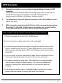
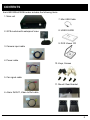
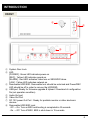
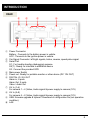
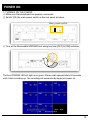
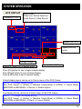
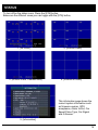
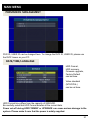
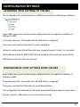
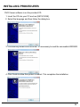
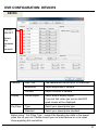
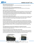
BRX
USER GUIDE
Models: BRX2004A & BRX2008A
VER 2.1.0
• Thank you for purchasing the BRX Micro DVR from D-TEG.
• Please ensure that you read and understand this USER GUIDE
and use it before connecting and installing this Recorder.
• Please store the USER GUIDE in an easily accessible location.
SAFETY ADVICE
CAUTION
RISK OF ELECTRIC SHOCK
DO NOT OPEN
CAUTION: TO REDUCE THE RISK OF ELECTRIC SHOCK,
DO NOT REMOVE COVER.
NO USER-SERVICEABLE PARTS INSIDE.
REFER SERVICING TO QUALIFIED SERVICE PERSONNEL.
Please make sure you follow the safety advice/instructions given in the user guide.
CAUTION
RISK OF EXPLOSION IF BATTERY IS REPLACED BY AN INCORRECT TYPE.
DISPOSE OF USED BATTERIES ACCORDING TO THE INSTRUCTIONS.
Battery for RTC(Real Time Clock) inside
CAUTION
Connect your vehicle’s power cable to the product after starting the vehicle.
The instant over voltage generated when starting up the vehicle may damage
the product if it is already connected.
CAUTION
Install the product where it does not block driver’s visibility and where there is
no airbag installed. This could cause an accident or might injure the passengers in
case of accident.
CAUTION
Damages due to production malfunction, loss of data, or other damages occurring
while using this product shall not be the responsibility of the manufacturer. Although
the product is a device used for recording videos, the product may not save all videos
in the case of a malfunction. In the case of an accident, the sensor may not recognize
the shock when the impact is light and as a result it may not begin recording
automatically.
WARNING:
TO PREVENT FIRE OR ELECTRIC SHOCK HAZARD,
DO NOT EXPOSE THIS APPLIANCE TO RAIN OR MOISTURE.
3
GPS Reception
1.
Activate the product in an area without large buildings to improve GPS
reception.
The commercial purpose GPS has the average range error of more than 15
meters and the range error could be more than 100 meters due to
environmental conditions like buildings, roadside trees etc.
2.
The temperature range for optimum operation of the GPS receiver in your
car is -10 ~ 50°C.
3.
When using the product for the first time or after a long period (more than
three days), it may take a little longer to recognize your current location.
It may take between five and thirty minutes to get GPS reception.
GPS reception may be impaired under the following circumstances.
1) If there is an object at the end of the GPS antenna
2) If your vehicle has metallic elements on the windshields
3) If equipment generating electromagnetic waves that interfere with the GPS
signal is installed in the vehicle e.g.: Other GPS devices such as a certain
type of wireless activated alarms, MP3 and CD players and camera alarms
using GPS.
4) If you are using a receiver connected by cable, electric interference can be
avoided by simply changing the location of the receiver (antenna).
5) On heavily overcast or cloudy days, if the vehicle is in a covered location
such as under a bridge or raised roadway, in a tunnel, an underground
roadway or parking area, inside a building or surrounded by high-rise
buildings.
6) If GPS signal reception is poor, it may take longer to locate your current
position when the vehicle is moving than when it is stationary.
4
CONTENTS
Each BRX2004A/2008A order includes the following items.
1. Main unit
7. Mini USB Cable
2. GPS module with waterproof case
3. Camera input cable
4. Power cable
8. USER GUIDE
9. DVR Viewer CD
10. Keys, Screws
5. Car signal cable
11. Mount/ Rear Bracket
6. Alarm IN/OUT, Video In/Out cable
5
INTRODUCTION
FRONT
①
②
③
⑧
⑨
④
⑤
⑥
⑦
① System Door Lock
② LED
[POWER] : Green LED indicates power-on
[REC] : Yellow LED indicates record-on
[ALARM] : Red LED indicates Video loss or SSD/HDD failure.
[LAN] : Yellow LED indicates network-on
③ Removable HDD/SSD: Removable lock should be unlocked and Power/REC
LED should be off in order to remove the HDD/SSD.
④ USB port: Ready for firmware upgrade & Upload / Download of configuration
file (set operation condition).
⑤ Audio Out port
⑥ Video Out Port
⑦ DC 12V power Out Port : Ready for portable monitor or other electronic
devices
⑧ Removable HDD/SSD Lock;
. Off → On: Turn on BRX and booting is completed in 42 seconds.
. On → Off: Turn off BRX. BRX is shut down in 15 seconds.
6
INTRODUCTION
FRONT
⑨ BUTTON
[SER] : Searches the recorded data.
[CH] : Changes the camera on display.
(Camera 1 → Camera 2 → Camera 3 ->.... ->Camera 8 → Camera 1)
[ESC] : Cancels or exits from the selected modes or menus.
[MENU] Enters into the menu.
[FN] : Funtion Key: used in combination with other buttons as follows;
FN + UP: Uploads the configuration file (operation settings, saved from the
DVR Viewer software through the USB memory stick.
FN + DOWN: Downloads the configuration file (operation settings) of the
current BRX to USB memory stick.
[STA] : Displays current status of BRX DVR operation.
INFORMATION: shows firmware version, GPS acceptance, Car Signal, GSensor)
[Arrow/ Direction]: Moves the highlight between items in the setting menu.
Change the live display layout: Left arrow(8 channels ), Right arrow( 4
channels)
[Time Delay Function]
In case of Power On /Off by ACC signal in vehicle;
Time delayed start
Off → On : Starts BRX 5 seconds later and booting is completed in 47 seconds.
Time delayed shutdown
On → Off : Stops recording immediately (record LED off) and shutdown takes
75 seconds till completed (power LED off)
7
INTRODUCTION
REAR
①
⑤
②
⑥
④
③
⑦
⑧
⑨
⑩
① Power Connector
Battery : Connects to the battery power in vehicle.
ACC : Connects to the ignition power in vehicle.
② Car Signal Connector: left/right signals, brake, reverse, speed pulse signal
③ Serial Port
S1 : For trouble shooting (debugging) purpose
S2(T) : Ready for interface to additional device
S3 : Connect the provided GPS
④ Main power Switch
⑤ Power out: Ready for portable monitor or other device (DC 12V OUT)
⑥ DIGITAL IO / AV OUT
Alarm in; 8 ports
Alarm Out: 2 ports
Video / Audio Out
⑦ AV In (1~4)
For camera 1 ~ 4 (Video, Audio signal & power supply to camera (12V)
⑧ AV In (5~8)
For camera 5 ~ 8 (Video, Audio signal & power supply to camera (12V)
⑨ USB: firmware upgrade & Upload / Download of configuration file (set operation
condition).
⑩ LAN
8
CONNECTION DIAGRAM
9
POWER ON
1. TURNING ON THE POWER
① Make sure that peripherals are properly connected.
② Switch「ON」the main power switch on the rear panel as below,
Main power switch
③ Turn on the Removable HDD/SSD lock using key from [OFF] to [ON] as below,
The front POWER LED will light up in green. Please wait approximately 42 seconds
until it start recording up. The recording will automatically begin just power on.
10
POWER OFF
2. TURNING OFF THE POWER
① Turn off the Removable HDD/SSD lock using key from [ON] to [OFF] as below,
The RECORD LED will be off immediately and the front POWER LED will be off in 15
seconds.
[System shutdown pop-up window]
② Power LED should be off in order to remove the Removable HDD/SSD from the DVR.
11
SYSTEM OPERATION
LIVE DISPLAY
CAMERA TITLE
Status icons:
Video loss, Motion Detection,
Audio Record, Video Record
Speed from GPS
Speed from car
pulse
Storage Usage
Alarm in, Alarm out, G-sensor icons
Current Date & Time
Press [CH] button to see a single channel display
Press [Right] button to see 4 channel display
Press [Left] button to see 8 channel display
Default display layout can be set in Device menu of the DVR Viewer.
NOTE – To change default display
Run DVR Viewer => Setting => Machine Config [New] or [OPEN] => Select Model
BRX2008A or BRX2004A => Device => Default Layout
Live display priority can be set in Event menu of the DVR Viewer.
NOTE – To change live display priority
Run DVR Viewer => Setting => Machine Config [New] or [OPEN] => Select Model
BRX2008A or BRX2004A => Event => Liveout Priority
12
SYSTEM OPERATION
LIVE DISPLAY ICONS
Video Loss, No Camera
Motion Detection
Audio Record
Continuous Record (RED)
Event Record (YELLOW)
Detect Alarm in 1
Detect Alarm in 2
Detect Alarm in 3
Detect Alarm in 4
Detect Alarm in 5
Detect Alarm in 6
Detect Alarm in 7
Detect Alarm in 8
Activate Alarm out 1
Activate Alarm out 2
Detect G-sensor Event
13
STATUS
To turn off/on the status icons, Press the [STA] button.
Below are the different views you can toggle with the [STA] button,
1. [All Icons]
3. [Without Icons, Camera titles]
2. [Without Icons]
4. [Without all icons]
This information page shows the
current system information such
as firmware version, GPS
acceptance, Alarm In/Out, Car
Speed Pulse Type, Car Signal
and G-Sensor.
5. [Information]
14
MAIN MENU
Press the [MENU] button on the front panel brings up the main menu below.
The on-screen menus allow you to check the configuration.
Only some settings can be changed here, please use provided DVR Viewer PC
Software to set up all the features of BRX.
All setup data is safe from power loss and stored in the internal flash memory of DVR.
1. SELECTING A MENU ITEM
Press the MENU Button to select a menu item.
If you press the ESC button, it returns to the previous menu.
2. POSITIONING THE YELLOW COLOR HIGHLIGHT
Use the up and down arrow buttons to position the yellow selector.
Press the left and right buttons to move to the next value in the selected menu.
3. SETTING AN OPTION
Press the left and right buttons to see additional options (only if you see the < and >
marks).
Press the up and down buttons if there are no marks.
15
MAIN MENU
CAMERA
Brightness and Contrast of each channel can be configured in this menu.
To change the Video or Camera title, please use the DVR Viewer on your PC.
Press [ESC] button to return to the previous mode.
SIGNAL
Speed pulse type and pulse standard can be configured in this menu.
Press [ESC] button to return to the previous mode.
16
MAIN MENU
G-SENSOR
G-sensor calibration can be configured in this menu.
G-SENSOR(X) 0, 90, 180, 270
-(Y) 0, 90, 180, 270
-(Z) 0, 90, 180, 270
[Example- Standard Installation]
FRONT (X axis): Front sides of BRX and car must be in line, facing the front side.
LEFT (Y axis): Left side of BRX must be facing the left side of car and BRX must be
horizontal, parallel with the ground.
TOP (Z axis): Top of BRX must be vertical to ground.
Standard installation
Z:Top
X:Front
Y:Left
Setting figure (X:0, Y:0, Z:0)
For more details, please refer to page 28.
G-sensor sensitivity level can be configured in this menu.
Sensitivity level 1 is dull, level 5 is very sensitive.
Press [ESC] button for returning to the previous mode.
X:Front
17
MAIN MENU
DISPLAY
This menu is to view/change the default display screen.
To change which screen is your default display screen, please use the DVR Viewer on
your PC.
Press [ESC] button for returning to the previous mode.
RECORD
Recording conditions such as Frame Rate, Resolution and Image Quality can be changed.
To change the Record set up, please use the DVR Viewer on your PC.
18
MAIN MENU
To change the Resolution, Quality, Pre-recording time, Post-recording time, please use
the DVR Viewer on your PC.
Change the channel and check the record set up per channel
To change the Record Normal/Event, fps, audio on/off, please use the DVR Viewer on
your PC.
Disk End Mode (Overwrite) ON/OFF. If “ON” the BRX will overview the oldest video
when the HDD/SDD becomes full. “OFF” setting will notify you when HDD/SDD is full.
To change the Disk End mode, please use the DVR Viewer on your PC.
Press [ESC] button for returning to the previous mode.
19
MAIN MENU
SYSTEM
DATE/TIME/LANGUAGE and NTSC/PAL can be configured in this menu.
Press [ESC] button for returning to the previous mode.
DATE/TIME/LANGUAGE
System time, Date format, Time format, Time zone, DST, GPS Time Synchronize can be
configured in this menu.
20
MAIN MENU
PERMISSION MANAGEMENT
DVR ID, USER ID can be changed here. To change the DVR ID, USER ID, please use
the DVR Viewer on your PC.
DATE/TIME/LANGUAGE
HDD Format,
HDD recovery,
Firmware upgrade,
Factory Default
can be done.
Video standard
(NTSC/PAL)
can be set here.
HDD Format time differs from the capacity of SSD/HDD.
Be carefully noted that HDD Format deletes all the current data.
Power cut-off during HDD FORMAT or UPRGADE can cause serious damage to the
system. Please make it sure that the power is safely supplied.
21
CONFIGURATION SETTINGS
UPLOADING YOUR SETTINGS TO THE BRX
The configuration file can be saved into a USB memory stick via DVR Viewer Software.
Insert USB memory stick containing the configuration file (set operation condition) to
USB port in BRX.
It may take around 5~10 seconds until the USB stick is recognized.
Then press and hold the [Fn] button & press [Up] Button.
Upload of configuration file will then start and a beep will sound 3 times, for 3 seconds.
When Upload is finished, [REC] LED will turn on and recording will start automatically.
USB memory stick can then be removed.
DOWNLOADING YOUR SETTINGS FROM THE BRX
Insert USB memory stick containing the configuration file (set operation condition) to
USB port in BRX.
It may take around 5~10 seconds until the USB stick is recognized.
Then press and hold the [Fn] button & press [Down] Button.
The configuration file download will then start automatically and a beep will sound twice.
It takes 1 second. USB memory stick can be then removed.
22
SOFTWARE USER GUIDE
BRX200A DVR Viewer Guide
[PC SYSTEM REQUIREMENT]
Recommended PC specifications for DVR Viewer software
OS
Windows XP, Windows Vista, Windows 7
CPU
Intel Core 2 Duo (2Ghz)or higher
RAM
1GB or higher
VGA Memory
256MB or higher
HDD Free space
120MB or higher
Display
1,024 x 768 pixel/High Color(16bit) or higher
External Device
Removable HDD (File System:Ext3)
Need to install Ext2Fsd Driver
If the PC does not meet the minimum system requirement, the DVR
Viewer may not function properly.
23
INSTALLING PROCEDURES
DVR Viewer software is on the provided CD.
1. Insert the CD into your PC and run [SETUP.EXE].
2. Select the language and then follow the dialog box.
3. Continuously install EXt2Fsd driver. It’s necessary to read the removable HDD/SSD.
4. Click Finish to allow the system to reboot. This completes the installation.
24
PC SOFTWARE & DVR VIEWER SETTINGS
The “DVR Viewer” icon will be displayed on your desktop. Click to run DVR viewer.
※ NOTE: To Un-install the “DVR Viewer BRX2004A”
Open the “Control Panel”
Select [Remove Program] and remove [DVR Viewer BRX2004A]
To set the DVR Viewer itself, Click the setting icon.
setting
This setting is for
DVR Viewer itself.
Set the DVR Viewer
Password.
[This password is for
DVR viewer itself.
This is different from
your DVR password
or stream password.]
It can change speed
unit from Km/h to mph.
Also can select Time
and Date format of
DVR Viewer.
25
DVR CONFIGURATION: SETTING FILE
To set the DVR configuration,
First, connect a USB memory stick into your PC’s USB slot.
Run “DVR Viewer BRX2000A” Software and click the setting icon.
setting
And then click Machine config [NEW]
Select your DVR model first, and then click OK.
If you already have a DVR configuration in your memory stick, click [OPEN].
Select “setting” file from your memory stick.
“setting” file is in the dvr_config folder as below,
“Setting” file
26
DVR CONFIGURATION: DEVICES
DEVICE
Camera
ON/OFF
Select
the
cameras
to
connect.
Camera
Cam Title
The camera title can be up to 10 characters.
Brightness
Adjust Brightness of camera
Contrast
Adjust Contrast of camera
Display
Default layout
Select default display layout.
If you set 2x2, when you turn on the DVR
quad screen will be displayed.
Car Pulse
Type
Select your speed pulse type
Standard
Select your speed pulse standard
Before using “ Car Pulse Type”, connect the Speed pulse cable to the speed
pulse line on your car. Please consult your car manufacturer or a car repair
shop regarding this connection.
27
DVR CONFIGURATION: G-SENSOR CALIBRATION
G-Sensor Calibration
If you install
FRONT (X axis): Front sides of BRX and car must be in line, facing the front side.
LEFT (Y axis): Left side of BRX must be facing the left side of car and BRX must be
horizontal, parallel with the ground.
TOP (Z axis): Top of BRX must be vertical to ground
Standard installation
Z:Top
X:Front
X:Front
Y:Left
Setting figure (X:0, Y:0, Z:0)
Different installation 1 - BRX top is facing the ceiling.
(X:0, Y:0, Z:0)
(X:0, Y:0, Z:180)
(X:0, Y:0, Z:270)
(X:0, Y:0, Z:90)
F : Front
TOP : Top
R : Right
RR : Rear
B : Bottom
L : Left
28
DVR CONFIGURATION: CALIBRATION OPTIONS
F : Front
TOP : Top
R : Right
Different installation 2 - BRX top is facing the ground.
(X:180, Y:0, Z:0)
(X:180, Y:0, Z:180)
(X:180, Y:0, Z:270)
(X:180, Y:0, Z:90)
Different installation 3
- BRX front is facing left side of the car.
(X:270, Y:0, Z:0)
(X:270, Y:180, Z:0)
Different installation 4
- BRX Bottom is facing left side of the car.
(X:90, Y:0, Z:0)
(X:270,
Y:90,
Z:0)
(X270,
Y:0,
Z:90)
(X180,
Y:90,
Z:0)
(X:90, Y:180, Z:0)
(X:90,
Y:90,
Z:0)
Different installation 5
- BRX top is facing front side of the car.
(X90,
Y:0,
Z:270)
RR : Rear
B : Bottom
L : Left
Different installation 6
- BRX top is facing rear side of the car.
(X270,
Y:0,
Z:270)
(X90,
Y:0,
Z:90)
(X:0,
Y:90,
Z:0)
29
DVR CONFIGURATION: G-SENSOR LEVELS
Set G-Sensor Trigger level [1(insensitive)~5(The most sensitive)]
If G-sensor sensitivity value is high (5), it may be too sensitive, it will detect even a
light impact or light turn. If G-sensor sensitivity value is a low setting (1), it might not
detect a notable incident.
Sensitivity should be set in consideration of a vehicle’s suspension and also the
road condition.
G sensor X value: Front & Back (i.e. hard brake or quick acceleration)
G sensor Y value: Left & Right (i.e sharp turn)
G sensor Z value: Up & Down (prominence and depression)
Remote controller Enable button.
(this feature will be available soon)
30
DVR CONFIGURATION: RECORD SETTINGS
RECORD
Audio Record
ON/OFF
Video Type
Camera
Select your Video Standard(Camera type.).
This Video Standard(NTSC/PAL) is just for FPS
calculation. This is different from your DVR video
standard. To change your DVR video standard, set
your video standard at service menu of DVR. Refer to
page 21.
FPS
NTSC: D1 60fps, HD1 120fps, CIF 240fps
PAL: D1 50fps, HD1 100fps, CIF 240fps
TYPE
No record
Normal: Continuous recording when powered
on
Event: Recording by event (trigger or shock)
Normal + Event: 1fps record before event.
Record according to the setting when event.
31
DVR CONFIGURATION: RECORD SETTINGS CONT’D
Remained FPS
Show remained FPS / Total FPS
Resolution
D1: 720x480(NTSC), 720x576(PAL)
HD1: 720x240(NTSC), 720x288(PAL)
CIF: 360x240 (NTSC), 360x288(PAL)
Quality
Normal: Small file size, low picture quality.
High:
Super: Large file size, good picture quality.
Event
Record
Pre
Pre-event-record time is 0~5sec.
Post
Post-event-record time is 0~1hour.
Encryption
Stream password.
Enter 4 number from 1000 to 9999 as a password.
Once you set it, playback can be done only with the
right password.
[Caution] Be careful not to forget the password once
you set it. For security reasons, loss of passwords will
require the SD card to be returned to the distributor.
Overwrite
The image data is overwrites the oldest files when the
SD memory is full.
32
DVR CONFIGURATION: MOTION DETECTION
EVENT
Motion Detection
To use motion detection as a Event, check the camera first.
Sensitivity
1(Insensitive)~5(The most sensitive)
Set Grid
Default setting: All area is motion detecting area.
To disable motion detect, click blocks and make it to black.
Record CH
Select motion event record channel
Alarm out1
Set alarm out 1 duration from 0~∞
Alarm out2
Set alarm out 2 duration from 0~∞
Live out
Set Live display channel
Live out
Duration
Set Live display duration. Live display channel will
automatically change to the default live display after duration.
33
DVR CONFIGURATION SETTING
Alarm Input
To use Alarm In as a Event, check the alarm first.
Title
Set Alarm In title
Type
Set Alarm In Type
Alarm In 1~4: Voltage ON / Voltage OFF.
Alarm In 5~8: Normal Close / Normal Open
Record CH
Select Alarm record channel
Alarm out1
Set alarm out 1 duration from 0~∞
Alarm out2
Set alarm out 2 duration from 0~∞
Live out
Set Live display channel
Live out
Duration
Set Live display duration. Live display channel will
automatically change to the default live display after duration.
34
DVR CONFIGURATION SETTING
Signal
Title
Set Signal title
Record CH
Select Signal record channel
Alarm out1
Set alarm out 1 duration from 0~∞
Alarm out2
Set alarm out 2 duration from 0~∞
Live out
Set Live display channel
Live out
Duration
Set Live display duration. Live display channel will
automatically change to the default live display after duration.
35
DVR CONFIGURATION: VEHICLE SPEED
G-Sensor / Speed
GPS Speed
Set GPS speed, Exceeding this speed will trigger.
Pulse Speed
Set Car speed pulse speed, Exceeding this speed will trigger.
Record CH
Select which channel will record when speed i
Alarm out1
Set alarm out 1 duration from 0~∞
Alarm out2
Set alarm out 2 duration from 0~∞
Live out
Set Live display channel
Live out
Duration
Set Live display duration. Live display channel will
automatically change to the default live display after duration.
36
DVR CONFIGURATION: VIDEO CHANNEL PRIORITY
Live out Priority
This menu is to set the default live display priority.
1 is the highest priority display channel on the live screen.
2x2_1 : quad mode (cam1~cam4)
2x2_2 : quad mode (cam5~cam8)
3x3 : 8 split mode (cam1~cam8)
If you set 2x2_1 as 1 and turn on the DVR, the first screen will be always quad
(Cam1~Cam4) mode.
37
DVR CONFIGURATION: SYSTEM SETTINGS
SYSTEM
Language
Set your DVR language
Date Format
Set your DVR Date Format.
Time Format
Set your DVR Time Format
Speed Format
Set your DVR Speed Format
Apply DST
Set Daylight Saving Time
Time Zone
Set your Time zone
Time Sync
(GPS)
Set time synchronize time.
Boot on or every day 0~23 o’clock
USER ID
Set Driver Name
DVR ID
Set Car plate number or Vehicle ID
38
Connecting Removable HDD/SSD to your PC
1. Connect Removable SSD/HDD to your PC through provided USB mini cable.
2. Run “DVR Viewer BRX2000A”
3. Click [HDD load] icon.
[HDD load] icon
4. Select HDD
[NOTE]
Up to 4 removable HDD/SSD
can be connected to a PC at the same time.
5. Then calendar Search screen will be on the screen.
6. Select Date
7. select time
8. Select minutes.
10. Click Search
39
Opening the Data Folder
Use this button after you download the whole removable HDD data into a folder
in your PC.
If you copied all removable HDD files include folders into the [aaa] folder as below,
click Open Data Folder button and then select [aaa] folder to open the data.
select [aaa] folder
And then click OK
40
Playback screen
Camera title (Resolution)
Date/Time
Speed Pulse speed/Signal/Google map/Alarm In1~8
Playback control
Buttons
Slide Bar
Playback can be controlled with the buttons in bottom. The slider helps for easy
searching of the desired playback position or time.
In case that the user wants to search the other date, click [Calendar Search]
Button at the upper layer of screen. Then Calendar Search windows open and
the other dates can be played back accordingly.
[Calendar Search] Button
For more information about calendar search, refer to page 47.
41
Main buttons / Playback control buttons
Main Buttons
HDD Load
Calendar Search
Print Image
File Load
Event Search
Backup
Close Data
Privacy Set
Backup List
View Information
Save Jpg
Setting
Select Layout
Save AVI
About
Playback control Buttons
Before
Reverse
Audio ON/OFF Volume control
Pause
Play
Next
Playback speed control
(x1, x0.5, x2, x4, x8, x16, x32)
Converting the captured file to JPEG format.
Recording the file which is currently played back in the software.
42
Select Display layout
Click [Select Layout] button and then window for layout selection appears.
[Select Layout] button
Window for layout selection
Click this icon for returning to the previous screen.
[Select Layout] button
To see 1 camera only, double-click the screen.
Or right-click on screen and select camera
Return to multi-screen mode, double click screen.
Display Ratio
Select display ratio among original, TV(4:3), fit to window
Mirror Mode
Software mirror ON/OFF function
43
Viewing GPS and G-Sensor Information
Click [View Information] button during playback.
[View Information] button
BRX can record not only video & audio data of 8 Channels but also useful driving
information of vehicles such as GPS position, speed, left/right signal, brake signal
and speed pulse & G-sensor information. In addition, 8 alarm inputs can be
interfaced and trigger the recording (such as overhead lights, brake, door opening).
All of the above information can be played back and analyzed through the BRX DVR
PC Viewer Software.
Check the box to see the information like G-sensor graph, Speed graph etc.
The data of G-Sensor (X : red, Y : green, Z : blue) & speed (grey) are displayed
as graphs and Alarms & Car Signals are displayed as dotted lines or continuous
lines upon its occurrence or trigger.
44
Google™ Maps Integration
Click [Google map] button during playback.
[Google map] button
To see the route & position on the Google
map, the GPS data should be recorded
with video.
To see the map, the PC must be
connected to the Internet.
Now here
The playback position will be shown on the map with an arrow.
The red line show the route taken.
45
Multi-Window Playback
The Main DVR viewer, Information Window, and Google Maps Window can be
displayed on the same monitor at the same time and their size can be adjusted
individually.
3 different windows can work as an integrated analysis software, which improves the
efficiency of the security/fleet management.
The following screen is the common example of the operation. Multi-monitors can be
supported and 3 windows can be separately displayed at different monitors.
46
Calendar Search
Click [Calendar Search] button during playback to search the other date.
[Calendar Search] button
Dates containing recorded data are to be marked with box of Orange color.
Once the selected date is clicked, the hours containing recorded data are
marked with Orange color, too.
Click on the selected hour opens the minute table with Orange color.
The selected hour/minute is marked in blue color.
After then, click [Search] Button.
47
Event Search
Click [Event Search] button to quickly search for events only.
[Calendar Search] button
[Event Search] BRX can access to the data of G-Sensor Trigger, Car Signal
Information, Alarm or speed with video/audio, which means that user can easily
search and playback the classified data by the different conditions.
This is the case of event search, the files of speed over 60Km GPS speed are
listed like below;
1. Set the search range first.
2. Set event
condition.
3. Click
Search.
4. Select an event to playback
This means GPS Speed/Car Pulse Speed
5. Click Goto Video
for playback
48
Privacy Set
The BRX can set up a Privacy region on each channel to protect the
people/information from unnecessary disclosure to public.
The set privacy region becomes blurred in case of back up the original data to
JPG, AVI and export to any other report.
Click [Privacy Set] button to set privacy region.
[Privacy Set] button
Click the area to hide on the picture and make it sure that the area changes.
[Before set the privacy region]
[After set the privacy region]
Privacy region
Select Camera
Each screen is divided to 256 regions for set Privacy setting.
49
Save JPG Files & Convert to AVI
Pause the playback and click [Save Jpg] button to make a JPG file.
[Save Jpg] button
Pause the playback and click [Save AVI] button to make an AVI file.
[Save AVI] button
50
Print Image
Pause the playback and click [Print Image] button to print out.
[Print Image] button
Type in the Title [Print Title] & any comments [Comment]
using the Keyboard.
51
Data Backup
Click [Backup] button to backup the files to the PC.
[Backup] button
Type means a folder name.
Need this to start backup.
Type in the Memo Title & Memo using the Keyboard.
And then set the Type (Folder name) and click start button.
52
Backup List Search
Click [Backup List] button to playback backup file.
[Backup List] button
Select Type to search.
Under selected type, file list shows up with the information of time, DVR ID, USER ID.
Select the required file and click [OK] Button.
53
About
Click [About] button to verify the product version and information.
[About] button
Click [HotKey] tap to check the hot key (simplified button) for the functions of DVR
Viewer Software.
54
Specifications
55
D-Teg America, LLC
600 Morse Ave., Unit A
877-601-9918
[email protected]
www.d-teg.us
MADE IN KOREA