1
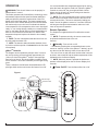
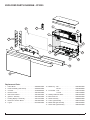
Service Manual
Model Number:
PF2325
PF3033
UL Part Number
690932XXXX
IMPORTANT SAFETY INFORMATION: Always read this manual first before attempting to service this fireplace. For your
safety, always comply with all warnings and safety instructions contained in this manual to prevent personal injury or property damage.
Dimplex North America Limited
1367 Industrial Road Cambridge ON Canada N1R 7G8
1-888-346-7539 www.dimplex.com
In keeping with our policy of continuous product development, we reserve the right to make changes without notice.
© 2014 Dimplex North America Limited
REV
PCN
DATE
00
-
2-OCT-14
7400790100R00
TABLE OF CONTENTS
Operation. . . . . . . . . . . . . . . . . . . . . . . . . . . . . . . . . . . . . . . . . . . . . . . . . . . . . . . . . . . 3
Maintenance. . . . . . . . . . . . . . . . . . . . . . . . . . . . . . . . . . . . . . . . . . . . . . . . . . . . . . . . . 5
Exploded Parts Diagram - PF2325. . . . . . . . . . . . . . . . . . . . . . . . . . . . . . . . . . . . . . . 6
Exploded Parts Diagram - PF3033. . . . . . . . . . . . . . . . . . . . . . . . . . . . . . . . . . . . . . . 7
Wiring Diagram . . . . . . . . . . . . . . . . . . . . . . . . . . . . . . . . . . . . . . . . . . . . . . . . . . . . . . 8
Main Control Board Replacement . . . . . . . . . . . . . . . . . . . . . . . . . . . . . . . . . . . . . . . 9
Flame LED Light and Media Light Assembly Replacement . . . . . . . . . . . . . . . . . . 9
Floating Display Assembly Replacement. . . . . . . . . . . . . . . . . . . . . . . . . . . . . . . . 10
Top Light Replacement. . . . . . . . . . . . . . . . . . . . . . . . . . . . . . . . . . . . . . . . . . . . . . . . . . 10
Heater Assembly Replacement. . . . . . . . . . . . . . . . . . . . . . . . . . . . . . . . . . . . . . . . . . . 10
Power Cord Replacement. . . . . . . . . . . . . . . . . . . . . . . . . . . . . . . . . . . . . . . . . . . . . . . . 11
Flicker Motor & Rod Replacement. . . . . . . . . . . . . . . . . . . . . . . . . . . . . . . . . . . . . . . 11
gWave assembly Replacement . . . . . . . . . . . . . . . . . . . . . . . . . . . . . . . . . . . . . . . . . . . 11
Logset Replacement . . . . . . . . . . . . . . . . . . . . . . . . . . . . . . . . . . . . . . . . . . . . . . . . . . . . 11
Electronics Junction Board Replacement. . . . . . . . . . . . . . . . . . . . . . . . . . . . . . . . . . 12
Lower & Media Light Assembly Replacement . . . . . . . . . . . . . . . . . . . . . . . . . . . . . . 12
Partially Reflective Glass Replacement. . . . . . . . . . . . . . . . . . . . . . . . . . . . . . . . . . . . 12
Troubleshooting Guide. . . . . . . . . . . . . . . . . . . . . . . . . . . . . . . . . . . . . . . . . . . . . . . 14
Always use a qualified technician or service agency to repair this fireplace.
! NOTE: Procedures and techniques that are considered important enough to emphasize.
CAUTION: Procedures and techniques which, if not carefully followed, will result in damage to the equipment.
WARNING: Procedures and techniques which, if not carefully followed, will expose the user to the risk of fire, serious
injury, or death.
2www.dimplex.com
OPERATION
WARNING: This electric firebox must be properly installed before it is used.
This firebox operates with Comfort$averTM technology, which
automatically adjusts the fan speed and heater wattage to
safely and precisely match the requirements of the room
based on the thermostat setting. The heater operates such
that once the room reaches the set point, the fan and heater
will continuously run at a low level, to maintain the desired
room temperature. If the temperature in the room rises significantly, i.e. sun coming through a window or a central furnace
turns on, the heater and fan will turn off and periodically turn
back on to circulate the air around the unit, until the room
temperature drops and requires the heater to be constantly
on again.
! NOTE: The unit is designed so that the fan will run continuously while the heater is on.
! NOTE: The element retains heat after shutdown, there
is a built in cool down period of 1 minute before the fan shuts
off completely.
gWaveTM Controls
The fireplace can be operated by a simple “wave” in-front of
the unit. By waving your hand vertically approximately 4 in.
(102 mm) in-front of the gWaveTM sensor in the upper right
hand corner of the unit, the unit and different control functions
can be activated. This is also indicated by the LED light turning
green.
There is a Gesture On/Off button located below the LED
pilot light which can be used to turn this feature On or Off.
It is recommended that a straightened paperclip be used to
press the button through the small hole. When the gWaveTM
controls are turned off, the green light will flash 4 times
before turning off and it will remain solid green when the
gWaveTM controls are active.
! NOTE: The unit is programmed to have a built in demonstration mode to exhibit all of the functions of the unit in a 95
second period of time. This can be activated by holding your
hand in front of the gWaveTM sensor for 7 seconds. When the
unit has gone through the demonstration mode once it will
return to the previous operation.
Remote Operation
The fireplace is supplied with an IR multifunction remote
control.
! NOTE: To operate correctly, the remote control must
be pointed towards the front of the unit.
Controls
1.
Standby: Turns unit On or Off.
→ Activated by pressing the corresponding button on the
remote or “waving” in-front of the gWaveTM. “Waving” up will
turn the unit On and “Waving” down will turn the unit Off.
• The unit will turn on with the same functions that it was set
to when it was turned Off and the intake temperature will be
indicated on the On Screen Display.
! NOTE: When any button is pressed the intake temperature will be displayed on the On Screen Display for 5
seconds.
2.
Flame On/Off: Turns the flame effect On or Off.
①
Figure 1
gWaveTM
Controls
Gesture On/Off
③
⑦
⑥
②
③
④
⑤
⑥
⑦
⑧
⑨
LED Pilot Light
⑩
⑩
⑪
3
→ Activated by pressing the corresponding button on the
remote or “waving” in-front of the gWaveTM - wave up to
turn on and wave down to turn off.
• When On the flame effect is visible in the unit.
3.
Heat On/Off: Turns the heater On or Off.
→ Activated by pressing the corresponding button on the
remote or holding your hand in-front of the gWaveTM for 3
seconds.
• Indicated by the icon and intake temperature being illuminated on the Floating Display™ and the heater turning On
or Off.
! NOTE: The heater can be operated when the flame is
not visible. In this case the
icon will remain on the Floating Display™ until the heater is turned off or the flames are
turned back on.
4.
Temperature Down: Decreases the heat output.
→ Adjusted by repeatedly pressing the corresponding button on the remote.*
• Indicated by setpoint temperature on the Floating Display™ decreasing and the speed of the fan decreasing to
reduce the amount of heat being projected into the room.**
5.
Temperature Up: Increases the heat output.
→ Adjusted by repeatedly pressing the corresponding button on the remote.*
• Indicated by the setpoint on the Floating Display™ increasing and the speed of the fan increasing to increase
the amount of heat being projected into the room.
* The first time the button is pressed the current temperature set point will be displayed for 5 seconds.
** The temperature can be adjusted from 5 °C to 30 °C (41
°F to 86 °F).
! NOTE: Pressing the
and °F.
then
will toggle between °C
6.
Eco: Runs the heater in a reduced wattage range
when activated.
→ Adjusted by pressing the corresponding button on the
remote when the heater is on.
• Indicated by the icon being illuminated on the Floating
Display™ and the speed of the fan will decrease proportionally.
7.
Boost: Turns On/Off the heater boost function.
Runs the unit at the full rated wattage.
→ Activated and adjusted by repeatedly pressing the corresponding button on the remote.
• Indicated by the heater running at full heat, for a predetermined amount of time, to quickly heat up a cold room/
space. The Boost can be set for a maximum of 20 minutes,
in 5 minute increments.
8.
Multi-Fire XD™: Scrolls through the different
media theme color presets for the media, flame base
and top lights.
→ Changed by repeatedly pressing the corresponding button on the remote.
• Cycles through the different preset ambient lighting settings of the unit, this includes different combinations of
colours of the top lighting, flame base and media lighting (if
applicable).
! NOTE: The last option is a personalized colour setting
(“P”), where using the buttons on the remote the lighting of
the unit can be adjusted to any shade of any colour. The
initial setting is no light (Red=0, Blue=0, Green=0) and can
be adjusted, while the display is flashing, by pressing the
outlined buttons (below) to adjust the tones.
Red Tones:
Green Tones:
Blue Tones:
increase and the
increase and
increase and
decrease.
decrease.
decrease.
9.
Brightness: Changes the brightness of the lights
in the unit.
→ Adjusted by repeatedly pressing the corresponding button on the remote.
• Indicated by the second digit on the Floating Display™
changing to show: “A” (high), “b” (low), “C” (high with media
flicker) and “d” (low with media flicker).
! NOTE: Media flicker is not an option on the Multi-Fire
XD™ levels 5, 6 or P.
10.
Sleep timer: Turns the unit off after a preset
duration (from 30 minutes (0.5h) to 8 hours, in ½ hour
increments).
→ Activated and adjusted by repeatedly pressing the corresponding button on the remote.
• Indicated by the Floating Display™ changing to indicate
30 minutes (0.5 h) through 8 hours. The fireplace will
automatically turn off when the sleep timer reaches zero
minutes. The sleep timer can be cancelled at any time by
pressing the sleep timer button repeatedly until the sleep
timer will no longer be visible.
11.Numerical Display
→ Default display will be the heater air intake temperature
or settings (eg. Multifire XD, Brightness, etc.)
Disable Heat
If desired, depending on the season, the heater on the unit
can be disabled. The unit will operate in the same fashion,
with remainder of the controls.
Pressing the
then
will enable or disable the heater.
When in the heat disable mode, the temperature reading/
setting on the On Screen DisplayTM displays nothing (“--”).
! NOTE: The heater will not work when the unit is controlled with gWave either.
Checking Software Level
The revision can be checked by press
same time.
and
at the
4www.dimplex.com
Resetting the Temperature Cutoff Switch
Should the heater overheat, an automatic cut out will turn
the fireplace off and it will not come back on without being
reset. It can be reset by unplugging the unit and waiting 15
minutes before plugging the unit back in.
Once power is restored the unit will start to reset itself.
During this process you will hear repeated beeps and the
Floating Display™ may turn on and off.
CAUTION: If you need to continuously reset the heater,
disconnect power and call Dimplex customer service at
1-888-DIMPLEX (1-888-346-7539).
Battery Replacement (Figure 3)
To replace the battery:
1. Slide battery cover open on the back of the remote
control.
2. Install one 3V (CR 2032) battery in the battery holder.
3. Close the battery cover.
Battery must be recycled or disposed of properly.
Check with your Local Authority or Retailer for recycling advice in your area.
MAINTENANCE
WARNING: Disconnect power before attempting any
maintenance or cleaning to reduce the risk of fire, electric
shock or damage to persons.
CAUTION: Allow adequate time for the element and
body casing to cool before attempting to clean the unit.
It is suggested that the heater be inspected regularly, for
cleanliness of the fan exhaust and intake grille, to ensure
optimal performance is maintained. The grille can be
cleaned by vacuuming off all dust and dirt.
Glass Cleaning
The front glass is cleaned in the factory during the assembly operation. During shipment, installation, handling,
etc., the front glass may collect dust particles, these can be
removed by dusting lightly with a clean dry cloth.
To remove fingerprints or other marks, the glass can be
cleaned with a damp cloth. The glass should be completely dried with a lint free cloth to prevent water spots. To
prevent scratching, do not use abrasive cleaners or spray
liquids on the glass surface.
Fireplace Surface Cleaning
To remove fingerprints or other marks, the exterior finish
can be cleaned with a damp cloth with a mild detergent.
The surface should be completely dried with a lint free cloth
to prevent water spots.
Servicing
Except for installation and cleaning described in this manual, an authorized service representative should perform any
other servicing.
5
EXPLODED PARTS DIAGRAM - PF2325
12
2
4
5
7
13
3
14
6
9
17
1
16
8
15
10
11
Replacement Parts:
1. Flicker Motor. . . . . . . . . . . . . . . . . . . . . . . . . . . 2000480100RP
10. Media Tray - Flat . . . . . . . . . . . . . . . . . . . . . . . 0441580100RP
2. Heater Assembly (with cutouts). . . . . . . . . . . . 2203650100RP
Curved. . . . . . . . . . . . . . . . . . . . . 0441580300RP
3. Cord Set. . . . . . . . . . . . . . . . . . . . . . . . . . . . . . 4100090204RP
11. Front Glass - Flat. . . . . . . . . . . . . . . . . . . . . . . 1026770100RP
4. Remote Control . . . . . . . . . . . . . . . . . . . . . . . . 3001250100RP
Curved. . . . . . . . . . . . . . . . . . . . 1026770300RP
5. Main Control Board . . . . . . . . . . . . . . . . . . . . . 3001260100RP
12. Partially Reflective Glass. . . . . . . . . . . . . . . . . 5902750100RP
6. gWaveTM Assembly. . . . . . . . . . . . . . . . . . . . . 3001400100RP
13. Brick Panet Set. . . . . . . . . . . . . . . . . . . . . . . . 0441600100RP
7. Floating Display™ Assembly. . . . . . . . . . . . . . 3001470100RP
14. Flicker Assembly . . . . . . . . . . . . . . . . . . . . . . . 5902830100RP
8. Electronics Junction Board. . . . . . . . . . . . . . . . 3001460100RP
15. Lower Light Assembly . . . . . . . . . . . . . . . . . . . 3001310100RP
9. Logset. . . . . . . . . . . . . . . . . . . . . . . . . . . . . . . 0441690100RP
16. Media LED Light Assembly . . . . . . . . . . . . . . . 3001330300RP
17. Flame LED Light Assembly . . . . . . . . . . . . . . . 3001330100RP
6www.dimplex.com
EXPLODED PARTS DIAGRAM - PF3033
12
2
4
6
5
7
13
3
14
9
17
1
16
8
11
15
10
Replacement Parts:
1. Flicker Motor. . . . . . . . . . . . . . . . . . . . . . . . . . . 2000480100RP
10. Media Tray. . . . . . . . . . . . . . . . . . . . . . . . . . . . 0441580200RP
2. Heater Assembly (with cutouts). . . . . . . . . . . . 2203650100RP
11. Front Glass . . . . . . . . . . . . . . . . . . . . . . . . . . . 1026770200RP
3. Cord Set. . . . . . . . . . . . . . . . . . . . . . . . . . . . . . 4100090204RP
12. Partially Reflective Glass. . . . . . . . . . . . . . . . . 5902750400RP
4. Remote Control . . . . . . . . . . . . . . . . . . . . . . . . 3001250100RP
13. Brick Panet Set. . . . . . . . . . . . . . . . . . . . . . . . 0441600300RP
5. Main Control Board . . . . . . . . . . . . . . . . . . . . . 3001260100RP
14. Flicker Assembly . . . . . . . . . . . . . . . . . . . . . . . 5902830200RP
6. gWave
Assembly. . . . . . . . . . . . . . . . . . . . . 3001400100RP
15. Lower Light Assembly . . . . . . . . . . . . . . . . . . . 3001310300RP
7. Floating Display™ Assembly. . . . . . . . . . . . . . 3001470100RP
16. Media LED Light Assembly . . . . . . . . . . . . . . . 3001330500RP
8. Electronics Junction Board. . . . . . . . . . . . . . . . 3001460100RP
17. Flame LED Light Assembly . . . . . . . . . . . . . . . 3001330300RP
TM
9. Logset. . . . . . . . . . . . . . . . . . . . . . . . . . . . . . . 0441540100RP
7
WIRING DIAGRAM
ONLY USED ON MEDIA MODELS
F1400 MAIN BOARD 3001260100
THERMAL
CUT OUT
THERMAL
CUT OUT
LINE IN
LINE T4
J1 LOG / MEDIA
NEUTRAL
NEUTRAL T5
LOG / MEDIA JUNCTION BOARD
NUMBER OF CONNECTIONS
IS BASED ON TYPE OF FIREBOX
NEUTRAL T6
J2 FLAME COLOUR
LED STRIP, RBG
HEATER ELEMENT
HEATER T1
FAN J9
J3 TOP LIGHT
TOP LIGHT ASSY
TOP LIGHT ASSY
FAN J10
J4 TOP LIGHT
NTC J11
MOTOR T2
J7 GESTURE
GESTURE ASSY
NEUTRAL T7
HEATER ASSEMBLY
FLICKER MOTOR
MAIN TO GESTURE HARNESS
J5 FLAME 1W
FLAME LED ASSY
TYPE OF CONNECTIONS
IS BASED ON TYPE OF FIREBOX
DISPLAY J8
DISPLAY BOARD ASSY
8www.dimplex.com
MAIN CONTROL BOARD REPLACEMENT
Tools Required: Phillips Head Screwdriver
Flat Head Screwdriver
Needle Nose Pliers
CAUTION: If unit was operating prior to servicing allow
at least 10 minutes for heating elements and top panel to
cool off to avoid accidental burning of skin.
WARNING: Disconnect power before attempting any
maintenance to reduce the risk of electric shock or damage
to persons.
1. Unplug the unit from power outlet.
2. Remove the firebox from the front of the mantel and
remove front glass assembly (glass lifts off).
CAUTION: Even though the glass is safety glass it
may break if bumped, struck of dropped. Care must be
taken when handling the glass.
3. Remove the loose media from the unit (if applicable).
Figure 3
Top Panel
Back Panel
Figure 4
gWave Assembly
Heater Assembly
Top LED Light
4. Remove the 14 screws around the back panel of the
firebox and the 3 along the middle of the panel (Figure
3).
5. Locate the main control board and transfer the wiring connections from the old board to the new board.
(Figure 4)
! NOTE: A flat head screwdriver can be used to gently
pry between the end of the connector and the main control
board to release the wires.
6. Release the main control board from the unit by using
needle nose pliers to depress the tab on the mounting
standoffs and gently lift the driver board off.
7. Properly orient and insert the new main control board.
8. Reassemble in the reverse order as above.
FLAME LED LIGHT AND MEDIA LIGHT
ASSEMBLY REPLACEMENT
Tools Required: Phillips Head Screwdriver
Small Adjustable Wrench
CAUTION: If unit was operating prior to servicing allow
at least 10 minutes for heating elements and top panel to
cool off to avoid accidental burning of skin.
WARNING: Disconnect power before attempting any
maintenance to reduce the risk of electric shock or damage
to persons.
1. Unplug the unit from power outlet.
2. Remove the firebox from the front of the mantel and
remove front glass assembly (glass lifts off).
CAUTION: Even though the glass is safety glass it
may break if bumped, struck of dropped. Care must be
taken when handling the glass.
3. Remove the loose media from the unit (if applicable).
4. Remove the 14 screws around the back panel of the
firebox and the 3 along the middle of the panel (Figure
3).
5. Locate the flame LED light assembly, at the bottom of
the unit. (Figure 4)
6. Locate and remove the two screws on either end securing the bracket, that the light assembly and the flicker
rod are attached to, and remove assembly (Figure 5).
7. Using the small adjustable wrench remove the 3 nuts to
remove the LED light assembly.
Figure 5
Mounting Screws
Media LED Light
Main Control Board
Flicker Motor
Floating Display
Flame LED Light Assembly
Assembly
Securing Nuts
Flame LED Light
9
8. Follow the wiring to the main control board and replace
with new connection.
9. Properly orient and insert the new LED light assembly.
10. Reassemble in the reverse order as above.
FLOATING DISPLAY ASSEMBLY
REPLACEMENT
Tools Required: Phillips Head Screwdriver
CAUTION: If unit was operating prior to servicing allow
at least 10 minutes for heating elements and top panel to
cool off to avoid accidental burning of skin.
WARNING: Disconnect power before attempting any
maintenance to reduce the risk of electric shock or damage
to persons.
1. Unplug the unit from power outlet.
2. Remove the firebox from the front of the mantel and
remove front glass assembly (glass lifts off).
CAUTION: Even though the glass is safety glass it
may break if bumped, struck of dropped. Care must be
taken when handling the glass.
3. Remove the loose media from the unit (if applicable).
4. Remove the 14 screws around the back panel of the
firebox and the 3 along the middle of the panel (Figure
3).
5. Locate the floating display assembly. (Figure 4)
6. Remove the 2 screws located at the top of the assembly, gently remove the board and surrounding bracket.
7. Follow the wiring to the main control board and replace
with new connection.
8. Properly orient and insert the new floating display assembly.
9. Reassemble in the reverse order as above.
TOP LIGHT REPLACEMENT
Tools Required: Phillips Head Screwdriver
Needle Nose Pliers
CAUTION: If unit was operating prior to servicing allow
at least 10 minutes for heating elements and top panel to
cool off to avoid accidental burning of skin.
WARNING: Disconnect power before attempting any
maintenance to reduce the risk of electric shock or damage
to persons.
1. Unplug the unit from power outlet.
2. Remove the firebox from the front of the mantel and
remove front glass assembly (glass lifts off).
CAUTION: Even though the glass is safety glass it
may break if bumped, struck of dropped. Care must be
taken when handling the glass.
3. Remove the loose media from the unit (if applicable).
4. Remove the 14 screws around the back panel of the
firebox and the 3 along the middle of the panel (Figure
3).
5. Locate the top light that requires to be replaced. (Figure 4)
6. Release door that houses the LED light board by pressing the tab to the left and opening the door.
7. Release the LED light board from the top panel by using needle nose pliers to depress the tab on the mounting standoffs and gently lift the board off.
8. Follow the wiring to the main control board and replace
with new connection.
9. Properly orient and insert the new board.
10. Reassemble in the reverse order as above.
HEATER ASSEMBLY REPLACEMENT
Tools Required: Phillips Head Screwdriver
CAUTION: If unit was operating prior to servicing allow
at least 10 minutes for heating elements and top panel to
cool off to avoid accidental burning of skin.
WARNING: Disconnect power before attempting any
maintenance to reduce the risk of electric shock or damage
to persons.
1. Unplug the unit from power outlet.
2. Remove the firebox from the front of the mantel and
remove front glass assembly (glass lifts off).
CAUTION: Even though the glass is safety glass it
may break if bumped, struck of dropped. Care must be
taken when handling the glass.
3. Remove the loose media from the unit (if applicable).
4. Remove the 14 screws around the back panel of the
firebox and the 3 along the middle of the panel (Figure
3).
5. Locate the heater assembly and disconnect the wiring
connections noting their original locations.
! NOTE: A flat head screwdriver can be used to gently
pry between the end of the connector and the switch to
release the wires.
6. Remove the 4 screws that secure the heater assembly
to the unit (2 on the top and 2 on the bottom). (Figure
6)
7. Properly orient and install the new heater assembly
and connect all of the wiring.
WARNING: Ensure wires do not come in contact with
moving parts by securing wires in wiring tie wraps.
8. Reassemble in the reverse order as above.
Figure 6
Top Mounting Screws
Bottom Mounting Screws
10www.dimplex.com
POWER CORD REPLACEMENT
Tools Required: Phillips Head Screwdriver
Needle Nose Pliers
CAUTION: If unit was operating prior to servicing allow
at least 10 minutes for heating elements and top panel to
cool off to avoid accidental burning of skin.
WARNING: Disconnect power before attempting any
maintenance to reduce the risk of electric shock or damage
to persons.
1. Unplug the unit from power outlet.
2. Remove the firebox from the front of the mantel and
remove front glass assembly (glass lifts off).
CAUTION: Even though the glass is safety glass it
may break if bumped, struck of dropped. Care must be
taken when handling the glass.
3. Remove the loose media from the unit (if applicable).
4. Remove the 14 screws around the back panel of the
firebox and the 3 along the middle of the panel (Figure
3).
5. Locate the power cord and disconnect the wiring connections noting their original locations.
! NOTE: A flat head screwdriver can be used to gently
pry between the end of the connector and the switch to
release the wires.
6. With needle nose pliers, grasp the power cord strain
relief grommet from inside the back of the bottom panel
and push while twisting to remove.
7. Install the new power cord.
8. Reassemble in the reverse order as above.
FLICKER MOTOR & ROD REPLACEMENT
Tools Required: Phillips Head Screwdriver
Flat Head Screwdriver
Needle Nose Pliers
CAUTION: If unit was operating prior to servicing allow
at least 10 minutes for heating elements and top panel to
cool off to avoid accidental burning of skin.
WARNING: Disconnect power before attempting any
maintenance to reduce the risk of electric shock or damage
to persons.
1. Unplug the unit from power outlet.
2. Remove the firebox from the front of the mantel and
remove front glass assembly (glass lifts off).
CAUTION: Even though the glass is safety glass it
may break if bumped, struck of dropped. Care must be
taken when handling the glass.
3. Remove the loose media from the unit (if applicable).
4. Remove the 14 screws around the back panel of the
firebox and the 3 along the middle of the panel (Figure
3).
5. Locate the flicker motor and flicker rod.
6. Remove the 2 screws that secure the flicker rod mount-
ing bracket to the unit.
7. Locate and disconnect the 2 motor assembly wires going to the main control board.
8. Remove the 2 motor mounting screws.
9. Separate the motor from the flicker connector and
remove.
10. Slide the flicker rod out of the snap-in bushing and
remove.
11. Reassemble in the reverse order as above.
GWAVE ASSEMBLY REPLACEMENT
Tools Required: Phillips Head Screwdriver
Flat Head Screwdriver
CAUTION: If unit was operating prior to servicing allow
at least 10 minutes for heating elements and top panel to
cool off to avoid accidental burning of skin.
WARNING: Disconnect power before attempting any
maintenance to reduce the risk of electric shock or damage
to persons.
1. Unplug the unit from power outlet.
2. Remove the firebox from the front of the mantel and
remove front glass assembly (glass lifts off).
CAUTION: Even though the glass is safety glass it
may break if bumped, struck of dropped. Care must be
taken when handling the glass.
3. Remove the loose media from the unit (if applicable).
4. To loosen the back panel to allow removal of the top
pane, remove the 4 screws along the top of the back
panel and the first screw along either side of the back
of the unit.
5. Remove the 12 screws around the top panel of the firebox and the 2 along the middle of the panel (Figure 3).
6. Remove the front portion of the panel, as well, by removing the 5 screws along the top.
7. Locate the gWave assembly (Figure 4).
8. Release the gWave assembly from the top panel by
gently depressing the tab on the top of the assembly
with the flat head screwdriver and gently remove.
9. Properly orient and connect the new assembly.
10. Reassemble in the reverse order as above.
LOGSET REPLACEMENT
Tools Required: Phillips Head Screwdriver
CAUTION: If unit was operating prior to servicing allow
at least 10 minutes for heating elements and top panel to
cool off to avoid accidental burning of skin.
WARNING: Disconnect power before attempting any
maintenance to reduce the risk of electric shock or damage
to persons.
1. Unplug the unit from power outlet.
2. Remove the firebox from the front of the mantel and
remove front glass assembly (glass lifts off).
11
Figure 7
Logset
5.
6.
7.
8.
9.
screw form either side that secure the logset.
Lift the logset out of the unit, being careful not to strain
the electronic cords.
Locate the electronics junction board and disconnect
the wiring connections noting their original locations.
(Figure 7)
Release the junction board from the bottom panel by
using needle nose pliers to depress the tab on the
mounting standoffs and gently lift the driver board off.
Properly orient and install the new electronics junction
board and connect all of the wiring.
Reassemble in the reverse order as above.
LOWER & MEDIA LIGHT ASSEMBLY
REPLACEMENT
Mirror Bracket
Lower Light
Electronics Junction Board
Assembly
CAUTION: Even though the glass is safety glass it
may break if bumped, struck of dropped. Care must be
taken when handling the glass.
3. Remove the brick panels from either side of the unit,
they are attached using magnets.
4. Gently place the unit its back to expose the bottom
of the unit. Remove the 4 screws from bottom and 2
screw form either side that secure the logset.
5. Lift the logset out of the unit, being careful not to strain
the electronic cords.
6. Remove the electrical connections from the electronics
junction board, replace with new logset connections.
7. Reassemble in the reverse order as above.
ELECTRONICS JUNCTION BOARD
REPLACEMENT
Tools Required: Phillips Head Screwdriver
Needle Nose Pliers
CAUTION: If unit was operating prior to servicing allow
at least 10 minutes for heating elements and top panel to
cool off to avoid accidental burning of skin.
WARNING: Disconnect power before attempting any
maintenance to reduce the risk of electric shock or damage
to persons.
1. Unplug the unit from power outlet.
2. Remove the firebox from the front of the mantel and
remove front glass assembly (glass lifts off).
CAUTION: Even though the glass is safety glass it
may break if bumped, struck of dropped. Care must be
taken when handling the glass.
3. Remove the brick panels from either side of the unit,
they are attached using magnets.
4. Gently place the unit its back to expose the bottom
of the unit. Remove the 4 screws from bottom and 2
Tools Required: Phillips Head Screwdriver
Needle Nose Pliers
CAUTION: If unit was operating prior to servicing allow
at least 10 minutes for heating elements and top panel to
cool off to avoid accidental burning of skin.
WARNING: Disconnect power before attempting any
maintenance to reduce the risk of electric shock or damage
to persons.
1. Unplug the unit from power outlet.
2. Remove the firebox from the front of the mantel and
remove front glass assembly (glass lifts off).
CAUTION: Even though the glass is safety glass it
may break if bumped, struck of dropped. Care must be
taken when handling the glass.
3. Remove the brick panels from either side of the unit,
they are attached using magnets (if applicable).
4. Gently place the unit its back to expose the bottom
of the unit. Remove the 4 screws from bottom and 2
screw form either side that secure the logset.
5. Lift the logset out of the unit, being careful not to strain
the electronic cords.
6. Locate the lower light assembly and disconnect the
wiring connection from the electronics junction board
noting the original location. (Figure 7)
7. Release the light assembly from the bottom panel by
using needle nose pliers to depress the tab on the
mounting standoffs and gently lift the light assembly off.
8. Properly orient and install the new light assembly and
connect all of the wiring.
9. Reassemble in the reverse order as above.
PARTIALLY REFLECTIVE GLASS
REPLACEMENT
Tools Required: Phillips Head Screwdriver
Flat Head Screwdriver
CAUTION: If unit was operating prior to servicing allow
at least 10 minutes for heating elements and top panel to
cool off to avoid accidental burning of skin.
12www.dimplex.com
WARNING: Disconnect power before attempting any
maintenance to reduce the risk of electric shock or damage
to persons.
1. Unplug the unit from power outlet.
2. Remove the firebox from the front of the mantel and
remove front glass assembly (glass lifts off).
CAUTION: Even though the glass is safety glass it
may break if bumped, struck of dropped. Care must be
taken when handling the glass.
3. Remove the brick panels from either side of the unit,
they are attached using magnets.
4. Gently place the unit its back to expose the bottom
of the unit. Remove the 4 screws from bottom and 2
screw form either side that secure the logset.
5. Lift the logset out of the unit, being careful not to strain
the electronic cords.
6. Locate and remove the 2 brackets that hold the partially
reflective glass in the unit (along the bottom). (Figure 7)
7. Gently pry the glass forward using a flat head screwdriver, being careful not to damage the corner tabs.
8. Transfer the rubber corner tabs from the old glass to
the new glass. Properly orient and install the new
glass.
9. Reassemble in the reverse order as above.
13
TROUBLESHOOTING GUIDE
PROBLEM
CAUSE
SOLUTION
PART NUMBER
General
Circuit breaker trips or fuse
blows when unit is turned
on
Short in unit wiring.
Trace wiring in unit.
Improper circuit current rating
Additional appliances may exceed the
current rating of the circuit breaker or fuse.
Plug unit into another outlet or install unit
on a dedicated 15 amp circuit.
Lights dim in room while the
unit is on
Unit is drawing close to circuit
current rating
Move the unit to another outlet or install
unit on a dedicated 15 amp circuit
Power cord gets warm
Normal Operation
The power cord may get slightly warm to
the touch when the heater is on
Defective power cord
Replace power cord if cord gets hot to the
touch.
Improper operation
Refer to Operation Section
No incoming voltage from the
electrical wall socket
Check Fuse/Breaker Panel
Loose wiring
Check wiring connections
Defective gWave assembly
Replace the gWave assembly
Improper operation
Refer to Operation Section
The batteries in the remote control are dead.
Install new battery into the remote control.
Defective remote control
Replace the remote control
Defective floating display assembly
Replace the floating display assembly
Loose wiring
Check wiring connections
Defective Flicker Motor
Replace Flicker Motor
Loose wiring
Check wiring connections
Flame LED light assembly is not
working
Replace flame LED light assembly
Defective main control board
Replace the main control board
3001260100RP
Flame Shudder
Defective Flicker Motor
Replace Flicker Motor
2000480100RP
Logset or Media bed does
not light up
Loose wiring
Check wiring connections
Media LED light assembly or
logset is not working
Replace media LED light assembly or
logset
Defective electronics junction
board
Replace electronics junction board
Defective main control board
Replace the main control board
4100090204RP
Appearance
Fireplace does not turn on
with the gWave controls
Fireplace does not turn on
with the Remote Control
Flame Frozen
Flame is not visible
3001400100RP
3001250100RP
3001470100RP
2000480100RP
23” - 3001330100RP
30” - 3001330300RP
Media
23” - 3001330300RP
30” - 3001330500RP
3001460100RP
3001260100RP
14www.dimplex.com
PROBLEM
CAUSE
SOLUTION
PART NUMBER
Heater
Heater is not turning on, but
flame effect is still functioning
Heater is turning off after a
couple of minutes of operation
Heater emits an odor
Improper operation
Refer to Operation Section
Loose wiring
Trace wiring in unit
Defective main control board
Replace the main control board
3001260100RP
Defective heater assembly
Replace heater assembly
2203650100RP
Improper operation
Refer to Operation Section
Build up of dirt/dust in Heater
Assembly
Ensure that exterior intake louvers and
firebox cavity are free of dirt/dust.
Defective heater assembly
Replace heater assembly
Normal Operation
Normal operation is when the heater emits
an odor for a brief period after the heater is
initially turned on. The heater is burning off
any dust accumulated during manufacturing or operation.
Defective heater assembly
Replace heater assembly
Dirty Heater Assembly
Ensure that exterior intake louvers and
firebox cavity are free of dirt/dust.
Defective heater assembly
Replace heater assembly
Flicker rod hitting or rubbing
against internal components
Ensure rod is straight and mounted properly in the bracket, spinning freely away from
other components. Replace if necessary.
Defective Flicker Motor
Replace Flicker Motor
2203650100RP
2203650100RP
Noise
Excessive noise with the
heater on
Grinding or excessive noise
with the heater off
2203650100RP
2000480100RP
15