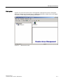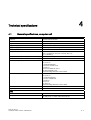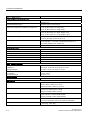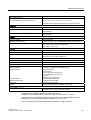
1
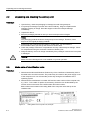
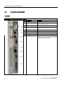
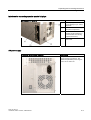
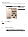
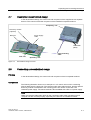
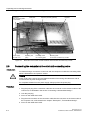
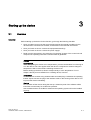
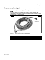
SIMATIC PC
Panel PC 870 V2
QuickStart
This manual applies to
devices with the order numbers
6AV774… and 6AV775…
Edition 03/2004
Introduction
1
Unpacking and connecting
the device
2
Starting up the device
3
Technical specifications
4
Safety Guidelines
This manual contains notices which you should observe to ensure your own personal safety as well as to avoid
property damage. The notices referring to your personal safety are highlighted in the manual by a safety alert
symbol, notices referring to property damage only have no safety alert symbol.
Danger
indicates an imminently hazardous situation which, if not avoided, will result in death or serious injury.
Warning
indicates a potentially hazardous situation which, if not avoided, could result in death or serious injury.
Caution
used with the safety alert symbol indicates a potentially hazardous situation which, if not avoided, may
result in minor or moderate injury.
Caution
used without safety alert symbol indicates a potentially hazardous situation which, if not avoided, may
result in property damage.
Notice
used without the safety alert symbol indicates a potential situation which, if not avoided, may result in
an undesirable result or state.
Wehn several danger levels apply, the notices of the highest level (lower number) are always displayed. If a
notice refers to personal damages with the safety alert symbol, then another notice may be added warning of
property damage.
Qualified Personnel
The device/system may only be set up and operated in conjunction with this documentation. Only qualified
personnel should be allowed to install and work on the equipment. Qualified persons are defined as persons who
are authorized to commission, to earth, and to tag circuits, equipment and systems in accordance with
established safety practices and standards.
Intended Use
Please note the following:
Warning
This device and its components may only be used for the applications described in the catalog or
technical description, and only in connection with devices or components from other manufacturers
approved or recommended by Siemens.
This product can only function correctly and safely if it is transported, stored, set up and installed
correctly, and operated and maintained as recommended.
Trademarks
All designations marked with ® are registered trademarks of Siemens AG. Other designations in this
documentation might be trademarks which, if used by third parties for their purposes, might infringe upon the
rights of the proprietors.
Copyright Siemens AG ,2004.All rights reserved
Reproduction, transmission or use of this document or its contents is not permitted without
express written authority. Offenders will be liable for damages. All rights, including rights
created by patent grant or registration of a utility model or design, are reserved.
Disclaimer of Liability
We have checked the contents of this manual for agreement with the hardware and
software described. Since deviations cannot be precluded entirely, we cannot guarantee
full agreement. However, the data in the manual are reviewed regularly, and any
necessary corrections will be included in subsequent editions. Suggestions for
improvement are welcomed.
Siemens AG
Automation and Drives Group
P.O. Box 4848, D-90327 Nuremberg (Germany)
Siemens AG 2004
Technical data subject to change
Siemens Aktiengesellschaft
Order No. A5E00299738
Table of contents
1
Introduction............................................................................................................................................. 1-1
1.1
2
3
4
Introduction ................................................................................................................................ 1-1
Unpacking and connecting the device .................................................................................................... 2-1
2.1
Safety Information...................................................................................................................... 2-1
2.2
Unpacking and checking the delivery unit ................................................................................. 2-2
2.3
Make note of identification data ................................................................................................. 2-2
2.4
Connecting elements ................................................................................................................. 2-4
2.5
Connect the PS/2 mouse ........................................................................................................... 2-6
2.6
Connect the PS/2 keyboard ....................................................................................................... 2-6
2.7
Description decentralized design ............................................................................................... 2-7
2.8
Connecting a decentralized design............................................................................................ 2-7
2.9
Connecting the computer unit-control unit connecting cable..................................................... 2-8
Starting up the device ............................................................................................................................. 3-1
3.1
Overview .................................................................................................................................... 3-1
3.2
Turn on device ........................................................................................................................... 3-2
3.3
Setting up Microsoft Windows operating system ....................................................................... 3-3
3.4
Installing applications and drivers .............................................................................................. 3-4
Technical specifications.......................................................................................................................... 4-1
4.1
General specifications, computer unit........................................................................................ 4-1
4.2
Ambient and environmental conditions, operator unit ............................................................... 4-4
4.3
Options....................................................................................................................................... 4-4
Panel PC 870 V2
QuickStart, Edition 03/2004, A5E00299738
iii
Panel PC 870 V2
QuickStart, Edition 03/2004, A5E00299738
Introduction
1.1
1
Introduction
The SIMATIC Panel PC is an industry-standard PC platform for demanding tasks in the field
of PC-based automation.
The SIMATC Panel PC provides detailed documentation in 5 languages in PDF format. The
documentation is available on the supplied "Documentation & Drivers" CD in the folder
"Documents\<language>\manual" and consists of the following parts:
• File "Panel_PC_870_V2_qs_e.pdf", QuickStart: This document
• File "Panel_PC_670_V2_870_V2_be_e.pdf", Operating instructions for the Panel PC
670/870 V2, Operator Unit: Refered to as "operating instructions for the operator unit" in
the following.
• File "Panel_PC_870_V2_re_e.pdf", Operating instructions for the Panel PC 670/870 V2,
Computer Unit: Refered to as "operating instructions for the computer unit" in the
following.
The CD-ROM drive is only available once the device has been switched on. This is why the
first steps for commissioning the device are descibed in this booklet. You are also supported
by screen dialogs during commissioning.
Notice
Carry out the tasks in the sequence described. Please follow all safety instructions
Read the documentation thoroughly once you have completed the commissioning. Please
read carefully the section "Safety information and general notes".
Panel PC 870 V2
QuickStart, Edition 03/2004, A5E00299738
1-1
Panel PC 870 V2
QuickStart, Edition 03/2004, A5E00299738
Unpacking and connecting the device
2.1
2
Safety Information
Electrical Connection
Warning
Unplug the device before every intervention and after disconnecting it from the power
supply.
Avoid contact with network lines and data transmission lines during thunderstorms, and do
not connect any lines during this time.
High frequency radiation
Caution
Unintentional operating situation
High frequency radiation, e.g. from cell phones, can cause unintentional operating situations
under some circumstances. For more details, consult the technical data in the "EMC
Requirements" chapter.
Handling and disposal of lithium batteries
Warning
Danger of explosion and the release of harmful substances!
Do not throw lithium batteries into fire, do not solder onto the cell body, do not open, do not
short circuit, do not reverse pole, do not heat above 100 °C, dispose of according to
regulations, and protect from direct sunlight, moisture and condensation.
Replace lithium batteries with the same brand or a brand recommended by the
manufacturer.
Dispose of used lithium batteries individually as hazardous waste in accordance with the
local regulations.
Panel PC 870 V2
QuickStart, Edition 03/2004, A5E00299738
2-1
Unpacking and connecting the device
2.2 Unpacking and checking the delivery unit
2.2
Unpacking and checking the delivery unit
Procedure
1. Upon delivery, check the packaging for damage incurred during transport.
2. If any transport damage is present at the time of delivery, lodge a complaint at the
shipping company in charge. Have the shipper confirm the transport damage
immediately.
3. Unpack the device.
4. Keep the packaging material in case you have to transport the unit again.
Notice
The packaging protects the device during transport and storage. Therefore, never
dispose of the original packaging material!
5. Please keep the enclosed documentation in a safe place. You will need the
documentation when you start up the device for the first time.
6. Check the package contents for completeness and any visible transport damage. Check
for completeness using the enclosed "Contents of Delivery" list.
7. Notify the delivery service in charge immediately if the packages contents are incomplete
or damaged.
Warning
Make sure that a damaged unit is not installed nor put into operation.
2.3
Make note of identification data
Procedure
1. Write down the Microsoft Windows Product Key of the Certificate of Authenticity COA in
the table at the end of this section. The product key is located on the power supply cover
of the computer unit. You will need the product key during the reinstallation of the
operating system.
2. Write down the manufacturer's number SVP and the order number of the computer unit,
e.g. "6AV..." in the table. If repairs are necessary, the device can be identified by the
service center on the basis of the SVP number and order number.
Both numbers are located on the rating label of the computer unit at the top of the
ventilator side.
Figure 2-1
2-2
Rating label of the computer unit, example
Panel PC 870 V2
QuickStart, Edition 03/2004, A5E00299738
Unpacking and connecting the device
2.3 Make note of identification data
3. Write down the model designation, the serial number e.g. "ST-...," the order number of
the control unit, e.g. "A5E," and the version of the device in the table. This data is located
on the rating label on the edge of the side of the control unit.
Figure 2-2
Rating label of the control unit, example
4. Write down the ethernet address of the device: The ethernet address is located in the
"main" menu of the BIOS setup, "Hardware Options > Ethernet Address."
Identification
1
Microsoft Windows Product Key
2
SVP number
Number
3
Order number of the computer unit
4
Power supply version
—
5
Approbation
—
6
Model designation
7
Serial number
8
Control unit order number
9
Device version
10
Ethernet address
Panel PC 870 V2
QuickStart, Edition 03/2004, A5E00299738
2-3
Unpacking and connecting the device
2.4 Connecting elements
2.4
Connecting elements
Interfaces
Arrangement of the ports on the front of the device
2-4
Pos
Description
Description
(1)
COM 1
Serial port 1 (V.24), 25-pin sub-D socket
(2)
PROFIBUS/MPI/DP
MPI interface (RS485, isolated potential),
optional 9-pin d-Sub socket
(3)
ETHERNET
RJ 45 Ethernet connection 10/100 Mbps
(4)
USB 2.0
USB connector. Right USB port 1, left USB
port 2.
(5)
COM2
Serial port 1 (V.24), 9-pin d-Sub socket
(6)
KEYBOARD
Connection for a PS/2 keyboard.
(7)
MOUSE
Connection for a PS/2 mouse.
(8)
LPT1
Parallel interface, 25-pin
(9)
DVI/VGA
DVI/VGA connection for CRT or LCD monitor
with DVI interface, VGA via DVI/VGA adapter
(included in Box PC package)
Panel PC 870 V2
QuickStart, Edition 03/2004, A5E00299738
Unpacking and connecting the device
2.4 Connecting elements
Interfaces for connecting operator panels / displays
Arrangement of the ports
(1)
LVDS display interface
for TFT displays up to 1024 x
768 pixels
(2)
I/O interface for connecting
front panel components
(3)
Access to the interfaces on
operator panels (closed by a
screwed metal cover during
shipment of Box PC)
(4)
Mounting screw for the steel
sheet cover
AC power supply
Position of the IEC power connector
Description
IEC power connector for the AC
power supply to the device. The
maximum permitted power range is
120 V AC to 230 V AC.
Panel PC 870 V2
QuickStart, Edition 03/2004, A5E00299738
2-5
Unpacking and connecting the device
2.5 Connect the PS/2 mouse
DC power supply
Position of the screw terminals
Description
Screw terminals for connecting the
DC power supply to the device
2.5
1
24 V DC
2
0 V DC
3
Protective conductor
Connect the PS/2 mouse
Procedure
1. Insert the cable of the external PS/2 mouse or another, external input device or pointing
device into the PS/2 mouse socket.
2.6
Connect the PS/2 keyboard
Procedure
1. Insert the cable of a PS/2 keyboard of your choice into the PS/2 keyboard socket.
Notice
Use a keyboard with a straight keyboard plug to leave room for other adjacent plugs.
2-6
Panel PC 870 V2
QuickStart, Edition 03/2004, A5E00299738
Unpacking and connecting the device
2.7 Description decentralized design
2.7
Description decentralized design
In the decentralized design, the control unit and computer unit are supplied as two separate
devices. The control unit and the computer unit are installed in separate locations.
Computing unit
Direct key module
(optional)
Power supply
cable
Receiver
Transmitter
(fitted)
Interconnecting
cable
USB cable
Operating Unit
Figure 2-3
Decentralized design overview
2.8
Connecting a decentralized design
Principle
In the decentralized design, the control unit and computer unit are in separate locations.
Components
The following illustration shows as an example of a 15" control unit on which a mounting
plate is attached to the back side. The remote module, also called receiver, and the optional
direct key module are attached to the mounting plate. The remote module has a AC
120/230V power supply. The remote module is also available with a DC 24 V power supply.
Note
Make sure that the cable strain reliefs for the connection cable at the operating unit and
computer unit are mounted properly, especially if the devices are installed at a slant.
Panel PC 870 V2
QuickStart, Edition 03/2004, A5E00299738
2-7
Unpacking and connecting the device
2.9 Connecting the computer unit-control unit connecting cable
Socket for
interconnecting cable
to transmitter
Power supply
120-240 V AC
Figure 2-4
2.9
USB cable
Operating unit
(rear)
Direct key module (optional)
Fastening screw
for mounting plate
Receiver
Mounting plate
for receiver and direct key module
Back side of the control unit with attached remote module and direct key module
Connecting the computer unit-control unit connecting cable
Introduction
For data exchange, connect the control unit and the computer unit with the connecting cable
which is illustrated in the "Options" section.
Warning
Avoid contact with network lines and data transmission lines during thunderstorms and do
not disconnect any lines during this time.
For complete isolation from the power supply, always pull out the power plug.
Procedure
1. Plug the jack plug of the connection cable into the connector on the remote module of the
control unit, as illustrated in the section "Connecting a decentralized design."
2. Lock the jack plug.
3. Screw on the cable strain relief.
4. Plug the male connector of the connection cable into the connector on the host module of
the computer unit, as illustrated in the chapter "Description", "Decentralized design".
5. Screw on the cable strain relief.
2-8
Panel PC 870 V2
QuickStart, Edition 03/2004, A5E00299738
Starting up the device
3.1
3
Overview
Checklist
Before starting up the device for the first time, go through the following checklist:
• Have you taken into account the proper ambient and environmental conditions for the
device and the connected I/O modules, as described in the technical information?
• Have you found out how to connect the equipotential bonding?
• Have you found out how to connect the power supply?
• Read over this information in the respective "Connecting" chapter of the control unit and
computer unit operating instructions. Please follow all guidelines.
Caution
Condensation
When transporting the device at low temperatures, prevent condensation from forming on
or in the device. The same applies when the device is subjected to extreme changes in
temperature. Wait 12 hours before switching the device on.
Before starting up the device, allow it to adjust slowly to room temperature. Do not
subject it directly to heat radiation from a heating device, however.
I/O modules
Connect the I/O modules using shielded cable and metal plugs. Otherwise the operating
license expires. Secure the plug of the interface cable on the housing of the device. This
improves the electrical shielding.
Start up
Do not switch off the device during the start up. Otherwise parts of the software will be
lost which are necessary for trouble-free operation.
Use the default values in the BIOS. Otherwise the operating system will not be installed
properly.
Panel PC 870 V2
QuickStart, Edition 03/2004, A5E00299738
3-1
Starting up the device
3.2 Turn on device
Requirements
The following devices have been connected:
• Computer unit
• Control unit
• PS/2 mouse
• PS/2 keyboard
For additional information, refer to computer unit operating instructions.
Procedure
1. Turn on device
2. Install Microsoft Windows operating system.
3. Install applications and drivers.
3.2
Turn on device
Procedure
1. Decentralized design only: Plug the supplied power supply cable into the AC/DC power
supply connector of the decentralized control unit and lock it in place. Connect the power
supply cable to the supply network. The "POWER" LED will light up.
2. Plug the power plug of the supplied power supply cable in the AC/DC power supply
connector of the computer unit.
3. Lock the power plug in place. For Panel PC 670 only: clamp the supplied ferrite core onto
the power supply cable. This step can also be performed later. For additional information,
please refer to the chapter "Connecting" in the computer unit operating instructions.
4. Plug the power supply cable of the computer unit into a socket with a grounded protective
conductor.
5. If your computer has a power switch, turn on the computer unit at the power switch.
In the central design, not until now will the "POWER" LED illuminate. The device is now in
operation and booting.
Note
Applies to the decentralized design: If the picture signal is missing, e.g. when the
computer unit-control unit connecting cable is not plugged in, the control unit screen is
white.
Self test
After connection to the power supply, the device performs a self test. During the self test,
the message "Press <F2> to enter SETUP" appears briefly.
When the self test is finished, the operating system will be loaded.
3-2
Panel PC 870 V2
QuickStart, Edition 03/2004, A5E00299738
Starting up the device
3.3 Setting up Microsoft Windows operating system
3.3
Setting up Microsoft Windows operating system
Introduction
Immediately following the start up of the computer unit, the setup assistant will start, which is
used to setup the parameters of the operating system.
Note
The dialogs of the setup assistants differ slightly in some places in the Windows 98 SE,
Windows NT 4.0, Windows 2000 and Windows XP operating systems.
In order to change to the next dialog, click on the "Continue" button. In order to change the
entry in the previous dialog, click on the "return" button.
Procedure
1. For Windows 98 and Windows NT 4.0 only: If required, enter the Microsoft Windows
Product Key which you wrote down in the identification data.
2. Accept the Microsoft licensing agreement.
3. For Windows 2000 and Windows XP only: Perform the regional settings of the operating
system.
4. Enter the company names and user names.
5. Enter the administrator password where necessary.
6. When connecting a computer unit to a network only: Enter the name of the computers for
identification.
7. When the dialog "SetDisplay" appears only: Click on the button with the screen size and
screen resolution which matches your device.
8. Restarting the operating system:
– Windows 98: Exit the operating system session and restart the computer unit.
– Windows NT 4.0: Click on the "Finish" button.
– Windows 2000 and Windows XP: automatic restart.
The operating system will be restarted. The system settings will be updated and the desktop
will be set up. The setup of the operating system is complete.
Panel PC 870 V2
QuickStart, Edition 03/2004, A5E00299738
3-3
Starting up the device
3.4 Installing applications and drivers
3.4
Installing applications and drivers
Introduction
After the computer unit is restarted, different dialogs appear on the screen with which the
drivers and applications can be installed.
Note
The dialogs overlap themselves. In order to change from one dialog to another, press the
key combination <Alt>+<Tab>.
Procedure
1. Change to the "SetDisplay" dialog. The dialog will appear here only if it did not appear
during the setup of the operating system.
2. Click on the button with the screen size and screen resolution which matches your
device.
Figure 3-1
Setdisplay
3. Change to the "Panel PC selector" dialog.
4. Select the model of your device.
3-4
Panel PC 870 V2
QuickStart, Edition 03/2004, A5E00299738
Starting up the device
3.4 Installing applications and drivers
Figure 3-2
Panel PC selector
The system settings of the device will be updated.
5. Change to the "Digital signature" dialog.
6. For Windows 2000 and Windows XP only: Click on the "Yes" button for every digital
signature.
Figure 3-3
Digital signature
7. Decentralized design only: Enter the path to the USB keyboard controller driver:
"C:/drivers…/USB Keyboard controller"
The touchware driver and USB keyboard controller driver will be installed.
Panel PC 870 V2
QuickStart, Edition 03/2004, A5E00299738
3-5
Starting up the device
3.4 Installing applications and drivers
8. Exit the operating system session and restart the computer unit. Otherwise the "Security
features" from "KeyTools" or "KeyHook" will not be activated.
Warning
Use "KeyTools" as described in the chapter "Additional Drivers and Applications."
Applies after the deactivation of the "security features" of "Key Tools" or after the
deinstallation of "KeyHook":
When the additional function keys F13 and S16 are used, or when using your own key
code table, serious malfunctions of the user software can occur, because the key codes
behind the function keys can also be activated by activating keys other than the
configured ones.
The next two steps apply to control units with touch screen panels: After the computer
unit is restarted, the "Touch screen calibration" dialog will appear. Carry out the following
steps carefully:
Figure 3-4
Touch screen calibration
9. Click on the "Calibrate" button. The dialog for touch calibration will appear.
10.Touch the cross hairs on the touch screen for at least 3 seconds and no longer than 10
seconds. The "Calibration complete" dialog will appear. Exit the calibration by clicking on
the "Done" button.
11.After installing the drivers and applications, exit the operating system session and restart
the computer unit.
The installation of the drivers and applications is complete. For more information, please
refer to the chapter "Additional drivers and applications" in the control unit operating
instructions.
Notice
After starting up your device, find out more about the particulars of the operating system in
the chapter "Starting up" in the computer unit operating instructions. More information about
the Microsoft Windows operating system is located in the chapter "Maintenance and
Service" in the computer unit operating instructions.
3-6
Panel PC 870 V2
QuickStart, Edition 03/2004, A5E00299738
Starting up the device
3.4 Installing applications and drivers
Raid system
Applies only to the raid system option: The application "Raid promise monitor" will appear
after every restart of the computer unit. For additional information, please refer to the chapter
"Functions" in the computer unit operating instructions.
Figure 3-5
Raid promise monitor
Panel PC 870 V2
QuickStart, Edition 03/2004, A5E00299738
3-7
Panel PC 870 V2
QuickStart, Edition 03/2004, A5E00299738
4
Technical specifications
4.1
General specifications, computer unit
General specifications
Order nos.
see the order documents
Dimensions
390x285x166 (WxHxD in mm)
Weight
Approximately 10 kg
Supply voltage (AC)
120 V to 230 V AC (85 to 264 V AC)
Supply voltage (DC)
24 V DC (20.4 to 28.8 V DC) *3
Line voltage frequency
50 - 60 Hz
Brief power failure to Namur
AC: min.20 ms (at 93 to 264 V AC)
(max. 10 events per hour; min. recovery time 1 s)
DC: no buffering
Max. power consumption AC (at 230 W secondary)
360 W (efficiency approx. 65%)
Max. power consumption DC (at 180 W secondary)
265 W primary (efficiency approx. 70%) *3
Max. current output (AC)
+5 V/25 A *
+3.3 V/10 A *
* 155 W total allowed
+12 V/12.2 A Peak 14.0A
–12 V/0.8 A
–5 V/0.5 A Limited to >0.8 A
+5 Vaux/2 A Peak 2.5 A
The total voltage amounts to max. 230W.
max. current output (DC)
+5 V/22 A *
+3.3 V/16 A *
* 140 W total allowed
+12 V/4.4 A Peak 8.0A
–12 V/0.5 A
–5 V/0.5 A
+5 Vaux/1 A
The total voltage amounts to max. 180W.
Noise emission
< 55 dB(A) to DIN 45635-1
Degree of protection
IP 20
Safety
Protection class
Protection class I to IEC 61140
Safety specifications
AC: EN 60950-1; UL60950; CSA C22.2 No 60950-01
DC: EN 61131-2; UL508; CSA C22.2 No 142
Panel PC 870 V2
QuickStart, Edition 03/2004, A5E00299738
4-1
Technical specifications
4.1 General specifications, computer unit
General specifications
Electromagnetic Compatibility (EMC)
Emitted interference (AC)
EN 55011 Class A, EN 61000-3-2 Class D
EN 61000-3-3;
Emitted interference (DC)
EN 55022 Class A, FCC Class A
Noise immunity:
Mains borne disturbance variables on supply lines
± 2 kV; (to IEC 61000–4–4; Burst)
± 1 kV; (to IEC 61000–4–5; Surge sym.)
± 2 kV; (to IEC 61000–4–5; Surge asym.)
Noise immunity on signal lines
± 1 kV;(to IEC 61000–4–4; Burst; length < 3 m)
± 2 kV; (to IEC 61000–4–4; Burst; length > 3 m)
± 2 kV; (to IEC 61000–4–5; surge; length > 30 m)
Immunity to discharges of static electricity
± 6 kV contact discharge; (to IEC 61000–4–2)
± 8 kV air discharge; (to IEC 61000–4–2)
Immunity to RF interference
10 V/m 80–1000 MHz, 80% AM (to IEC 61000–4–3)
10 V/m 900 MHz u. 1.89 GHz, 50% ED (to IEC 61000–4–3)
10 V 9 KHz-80MHz (to IEC 61000–4–6)
Magnetic field
30 A/m, 50 Hz (to IEC 61000–4–8)
Climatic Conditions
Temperature
tested to IEC 60068–2–1, IEC 60068–2–2, IEC 60068–2–14,
-In operation
+ 5 °C to + 45 °C
-Storage/transport
– 20 °C to +60 °C
-Gradient
max. 10°C/h in operation, 20°C/h storage, no condensation
Relative humidity
tested to IEC 60068–2–78, IEC 60068–2–30
-in operation
5 % to 80 % at 25 °C (no condensation)
-Storage/transport
5 % to 95 % at 25 °C (no condensation)
Mech. Ambient conditions
Vibration
tested to DIN IEC 60068–2–6
Operation *1 *2
Storage/transport
10 to 58 Hz: 0.075 mm, 58 to 500 Hz: 9.8 m/s2
5 to 9 Hz: 3.5 mm, 9 to 500 Hz: 9.8 m/s2
Shock resistance
-In operation
-Storage/transport
tested according to IEC 60068–2–27, IEC 60068–2–29
50 m/s2, 30 ms,
250 m/s2, 6 ms,
Special features
Quality assurance
to ISO 9001
Motherboard
Processor
Pentium IV 2.4GHz (up to 45°C)
Intel ® Celeron 2.0GHz (up to 45°C)
Pentium IV Mobile 2.2GHz (up to 45°C)
Internal processor cache
Pentium IV 2.4 GHz 512 KB
Pentium IV 2.0GHz Celeron 128 KB
Pentium IV Mobile 2:2GHz, 512 KB
Front Side Bus
Pentium IV 2.4GHz 533 MHz FSB
Intel ® Celeron IV 2.0GHz 400 MHz FSB
Pentium IV Mobile 2.2GHz, FSB 400 MHz
RAM
3 sockets, max. 3 GB SDRAM DDR266 (PC2100)
For memory expansion, refer to the order documentation
Free expansion slots
2 shared ISA/PCI, long
2 x PCI, long, 1 ISA, long
4-2
Panel PC 870 V2
QuickStart, Edition 03/2004, A5E00299738
Technical specifications
4.1 General specifications, computer unit
General specifications
Max. permissible current input per ISA slot
5 V/ 2 A, 12 V/ 0.3 A, -12 V/ 0.05 A
Max. permissible current input per PCI slot
5 V/ 2 A or 3.3 V/ 2A, 12 V/ 0.3 A, -12 V/ 0.05 A
The total power consumption (all slots) may not exceed 50 W
Disk drives
Floppy drive *2
3.5” (1.44 MB) / 3.5”
Hard disk drive
3.5” EIDE, UDMA, for hard disk capacity, refer to the order
documentation
CD–ROM, DVD–ROM/CD–RW *2
EIDE, UDMA33, for information on features, refer to the order
documentation
Graphics
Graphic controller
VIA ProSavage8
Graphic controller memory
Graphic memory 8, 16 or 32 MB SDRAM, uses system memory
Resolutions/frequencies/color depth
CRT: up to 1600x1200 at 60 Hz / 16-bit colors
CRT: 1280 x 1024 at 100 Hz / 32-bit colors
LCD: 1280 x 1024 / 18-bit
Interfaces
COM1
Serial port 1, 25-pin D-sub connector
COM2
Serial port 2, 9-pin D-sub connector
LPT1
Parallel port (standard, EPP mode)
Connection for printer with parallel port
DVI
Port for external CRT / LCD monitor
Keyboard
PS/2 keyboard connection
Mouse
PS/2 mouse connection
USB 2.0
2 x external at the interface side
PROFIBUS / MPI interface potential isolated
- Transmission rate
- Operating mode
- Physical interface
- Memory address area
- Interrupts
9-pin d-sub socket
- 9.6 Kbps to 12 Mbps, configurable per SW
- potential isolated:
Data lines A,B
Control lines RTS AS, RTS_PG
5 V power supply (max. 90 mA)
- grounded:
Shielding of the DP12 cable
- RS485, potential isolated
- configured automatically
- configured automatically
Ethernet
Ethernet interface (RJ45), VIA MAC. VT6103 PHy
Status displays on device
FD access (at the FD drive on the side of the housing)
CD-ROM access (at the CD drive, if installed)
1) Restriction for CD-ROM and DVD-ROM/CD-RW drives:
CD-ROM or DVD-ROM/CD-RW 10 to 58 Hz: 0.019 mm, 58 to 500 Hz: 2.5 m/s2
2) Restrictions for DVD-ROM/CD-RW: burner operation is only allowed without external
disruptions and at an ambient temperature between +5° C to +40°C
3) DC power supply only together with Pentium 4 Mobile 2.2 GHz processor
Panel PC 870 V2
QuickStart, Edition 03/2004, A5E00299738
4-3
Technical specifications
4.2 Ambient and environmental conditions, operator unit
4.2
Ambient and environmental conditions, operator unit
Mechanical conditions
Tested according to
Vibration load during operation
10 to 58 Hz: 0.075 mm, 58 to 500 Hz: 1 g
IEC 60068-2-6
Shock load during operation
50 m/s2, 30 ms, 3 shocks
IEC 60068-2-29
Ambient environmental conditions
Heat dissipation
by means of natural convection
Temperature limit values
during operation
with CD-RW/DVD drive
during storage/transport
5 °C... 45 °C
5 °C... 40 °C
-20 °C... 60 °C
Tested according to
IEC 60068-2-1, IEC 60068-2-2:, IEC 60068-2-14
Rel. humidity limit values
during operation
during storage/transport
5 ... 85 % at 25 °C
Tested according to
IEC 60068-2-3, IEC 60068-2-30, IEC 60068-2-56
Temperature change
Maximum 10 K/h
Condensation
not permissible
Supply air
No corrosive gases
4.3
5 ... 95 % at 25 °C (+77 °F)
Options
Components
The options comprise the following components:
Options
Order No.
Direct key module
6AV7671-7DA00-0AA0
Film for protecting the touch screen panel against dirt and
scratches
for 12" touch screen varaiant
for 15" touch screen variant
6AV7671-2BA00-0AA0
6AV7671-4BA00-0AA0
Labeling strips
for 10" keyboard variant
for 12" keyboard variant
for 15" keyboard variant
6AV7671-0CA00-0AA0
6AV7671-3CA00-0AA0
6AV7671-5CA00-0AA0
The printing templates for the labelling strips can be obtained from the internet address in the
preface.
4-4
Panel PC 870 V2
QuickStart, Edition 03/2004, A5E00299738
Technical specifications
4.3 Options
Computer unit-control unit connecting cable
For data exchange in the decentralized design, connect the remote module and the host
module with the up to 20 meters long green connecting cable.
Caution
Do not open the plug of the connecting cable and do not undo the connecting cable.
Otherwise the HF properties of the connecting cable will become irreversibly altered. Perfect
functioning is then no longer guaranteed.
Male connector for
connecting to
computing unit
Female connector
for connecting to
operating unit
Figure 4-1
Cable for connecting control unit and computer unit
Features
Cable connector at the computer unit
Cable connector at the control unit
Connector type
15pol. Sub-D male connector
15pol. Sub-D jack plug
Connector design
45° angle
straight
Panel PC 870 V2
QuickStart, Edition 03/2004, A5E00299738
4-5
Panel PC 870 V2
QuickStart, Edition 03/2004, A5E00299738