1
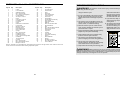
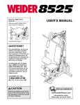
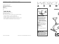
ORDERING REPLACEMENT PARTS
If you encounter any difficulties with this product, or if you need to order replacement parts, call the ICON Health
& Fitness, Ltd. office, or write:
ICON Health & Fitness, Ltd.
Customer Service Department
Unit 4, Revie Road Industrial Estate
Revie Road
Beeston
Leeds, LS118JG
UK
Model No. WLEMEX14830
Serial No. __________________
Tel:
Serial
Number
Decal
08457 089 009
Outside the UK: 0 (444) 113 387 7133
Fax: 0 (444) 113 387 7125
When ordering parts, please be prepared to give the following information:
• the MODEL NUMBER of the product (WLEMEX14830)
QUESTIONS?
• the NAME of the product (WESLO® AERO A8 exercise cycle)
As a manufacturer, we are committed to providing complete
customer satisfaction. If you
have questions, or if there are
missing parts, please call:
• the SERIAL NUMBER of the product (see the front cover of this manual)
• the KEY NUMBER and DESCRIPTION of the parts (see page 10)
08457 089 009
Or write:
ICON Health & Fitness, Ltd.
Customer Service Department
Unit 4
Revie Road Industrial Estate
Revie Road
Beeston
Leeds, LS118JG
UK
email: [email protected]
CAUTION
Read all precautions and instructions in this manual before
using this equipment. Save this
manual for future reference.
Part No. 201734 R0903A
Printed in Ch i n a © 2003 ICON Health & Fitness, Inc.
USER’S MANUAL
EXPLODED DRAWING—Model No. WLEMEX14830
R0903A
22
22
20
26
24
21
21
16
30
TABLE OF CONTENTS
9
4
23
IMPORTANT PRECAUTIONS . . . . . . . . . . . . . . . . . . . . . . . . . . . . . . . . . . . . . . . . . . . . . . . . . . . . . . . . . . . . .3
BEFORE YOU BEGIN . . . . . . . . . . . . . . . . . . . . . . . . . . . . . . . . . . . . . . . . . . . . . . . . . . . . . . . . . . . . . . . . . . .4
ASSEMBLY . . . . . . . . . . . . . . . . . . . . . . . . . . . . . . . . . . . . . . . . . . . . . . . . . . . . . . . . . . . . . . . . . . . . . . . . . . .5
HOW TO USE THE EXERCISE CYCLE . . . . . . . . . . . . . . . . . . . . . . . . . . . . . . . . . . . . . . . . . . . . . . . . . . . . . .7
MAINTENANCE . . . . . . . . . . . . . . . . . . . . . . . . . . . . . . . . . . . . . . . . . . . . . . . . . . . . . . . . . . . . . . . . . . . . . . . .8
CONDITIONING GUIDELINES . . . . . . . . . . . . . . . . . . . . . . . . . . . . . . . . . . . . . . . . . . . . . . . . . . . . . . . . . . . . .9
PART LIST . . . . . . . . . . . . . . . . . . . . . . . . . . . . . . . . . . . . . . . . . . . . . . . . . . . . . . . . . . . . . . . . . . . . . . . . . . .10
EXPLODED DRAWING . . . . . . . . . . . . . . . . . . . . . . . . . . . . . . . . . . . . . . . . . . . . . . . . . . . . . . . . . . . . . . . . .11
ORDERING REPLACEMENT PARTS . . . . . . . . . . . . . . . . . . . . . . . . . . . . . . . . . . . . . . . . . . . . . . . .Back Cover
10
40
13
32
45
27
19
43
15
43
34
15
45
34
11
33
16
28
37
6
17
28
20
6
38
46 29
45
14
6 37 28
37
6
17
35
20
13
7
31
37
3
44
54
55
56
54
5
36
56
47
52
25
18
7
3
1
7
41
38
42
49
7
5
53
3
8
50
51
49
48
51
WESLO is a registered trademark of ICON Health & Fitness, Inc.
2
3
2
11
12
39
PART LIST—Model No. WLEMEX14830
Key No. Qty.
1
2
3
4
5
6
7
8
9
10
11
12
13
14
15
16
17
18
19
20
21
22
23
24
25
26
27
28
29
1
1
4
1
4
4
4
1
2
1
1
1
1
1
3
1
1
1
1
3
2
2
2
1
1
1
1
4
1
Description
Key No. Qty.
Frame
Front Stabiliser
Stabiliser Endcap
M4 x 15mm Screw
3/8” x 65mm Carriage Bolt
Curved Washer
3/8” Nylon Locknut
Pulley
5/16” Nylon Locknut
Left Side Shield
Left Pedal
Crank
Resistance Control/Cable
Lower Cable
M8 Nylon Locknut
Extension Wire
Reed Switch/Wire
M10 x 40mm Bolt
Upright
M5 x 15mm Screw
Handlebar Foam
Handlebar Endcap
5/16” x 35mm Carriage Bolt
Handlebar
16.5mm Spacer
Console
M5 x 12mm Screw
M8 x 20mm Button Screw
M8 Nylon Locknut
30
31
32
33
34
35
36
37
38
39
40
41
42
43
44
45
46
47
48
49
50
51
52
53
54
55
56
#
1
1
1
1
2
1
1
4
1
1
1
1
1
3
1
6
1
1
1
3
1
2
1
1
2
2
2
1
R0903A
Description
Console Mount
Idler Bracket
Seat
Seat Post
Side Shield Cover
Frame Bushing
Seat Knob
Split Washer
Crank Bearing Assembly
Right Pedal
Right Side Shield
Magnet
M8 x 15mm Button Bolt
M8 Flat Washer
Belt
M5 x 25mm Machine Screw
M10 Nylon Locknut
Idler Wheel
Flywheel
3/8” Nut
3/8” Jamnut
Adjustment Assembly
Spring
Rear Stabiliser
Wheel
M5 Nylon Locknut
M5 x 35mm Button Bolt
User’s Manual
Note: “#” indicates a non-illustrated part. Specifications are subject to change without notice. See the back cover
of this manual for information about ordering replacement parts.
IMPORTANT PRECAUTIONS
WARNING:
To reduce the risk of serious injury, read the following important precautions
before using the exercise cycle.
1. Read all instructions in this manual before
using the exercise cycle.
10. When adjusting the seat, make sure that the
shaft of the seat knob is inserted into one of
the holes in the seat post (see HOW TO
ADJUST THE SEAT on page 7). Do not insert
the seat knob under the seat post.
2. It is the responsibility of the owner to ensure
that all users of the exercise cycle are adequately informed of all warnings and precautions.
11. If you feel faint, dizzy, or short of breath
whilst exercising, stop immediately and begin
cooling down.
3. The exercise cycle is intended for home use
only. Do not use the exercise cycle in a commercial, rental, or institutional setting.
12. The warning decal shown below is found on
the exercise cycle in the indicated location. If
the decal is missing or illegible, call 08457
089 009 and order a free replacement decal.
Apply the decal in the location shown.
4. Place the exercise cycle on a level surface.
Cover the floor beneath the exercise cycle to
protect the floor or carpet.
5. Inspect and properly tighten all parts regularly.
Replace any worn parts immediately.
6. Keep children under age 12 and pets away
from the exercise cycle at all times.
7. The exercise cycle should not be used by
persons weighing more than 115 kg (250 lbs.).
8. Do not wear loose clothing that could
become caught on the exercise cycle. Always
wear athletic shoes for foot protection.
9. Keep hands and feet away from moving parts.
WARNING:
Before beginning this or any exercise program, consult your physician. This
is especially important for persons over the age of 35 or persons with pre-existing health problems.
Read all instructions before using. ICON assumes no responsibility for personal injury or property
damage sustained by or through the use of this product.
10
3
CONDITIONING GUIDELINES
BEFORE YOU BEGIN
Thank you for selecting the new WESLO® AERO A8
exercise cycle. The AERO A8 exercise cycle is
designed to let you enjoy effective, low-impact
workouts in the convenience and privacy of your own
home.
Customer Service Department at 08457 089 009. To
help us assist you, please note the product model
number and serial number before calling. The model
number is WLEMEX14830. The serial number can be
found on a decal attached to the exercise cycle (see
the front cover of this manual for the location).
For your benefit and safety, read this manual carefully before using the exercise cycle. If you have
questions after reading this manual, please call our
Aerobic Exercise
WARNING:
Before beginning this
or any exercise program, consult your physician. This is especially important for individuals over the age of 35 or individuals with preexisting health problems.
If your goal is to strengthen your cardiovascular system, your exercise must be “aerobic.” Aerobic exercise
is activity that requires large amounts of oxygen for
prolonged periods of time. This increases the demand
on the heart to pump blood to the muscles, and on the
lungs to oxygenate the blood. For aerobic exercise,
adjust the intensity of your exercise until your heart
rate is near the highest number in your training zone
as you exercise.
Before reading further, please familiarize yourself with
the parts that are labeled in the drawing below.
The following guidelines will help you to plan your
exercise program. Remember that proper nutrition and
adequate rest are essential for successful results.
HOW TO MEASURE YOUR HEART RATE
Console
Handlebar
Resistance Knob
EXERCISE INTENSITY
To measure your heart
rate, stop exercising and
place two fingers on your
wrist as shown. Take a
six-second heartbeat
count, and multiply the
result by 10 to find your
heart rate. For example,
if your six-second heartbeat count is 13, your heart
rate is 130 beats per minute. (A six-second count is
used because your heart rate will drop rapidly when
you stop exercising.)
Whether your goal is to burn fat or to strengthen your
cardiovascular system, the key to achieving the
desired results is to exercise with the proper intensity.
The proper intensity level can be found by using your
heart rate as a guide. The chart below shows recommended heart rates for fat burning, maximum fat burning, and cardiovascular (aerobic) exercise.
Seat
WORKOUT GUIDELINES
Each workout should include the following three parts:
Seat Knob
Wheel
Pedal
A warm-up, consisting of 5 to 10 minutes of stretching
and light exercise. A proper warm-up increases your
body temperature, heart rate, and circulation in preparation for exercise.
To find the proper heart rate for you, first find your age
at the bottom of the chart (ages are rounded off to the
nearest ten years). Next, find the three numbers
above your age. The three numbers are your “training
zone.” The lowest number is the recommended heart
rate for fat burning; the middle number is the recommended heart rate for maximum fat burning; the highest number is the recommended heart rate for aerobic
exercise.
Training zone exercise, consisting of 20 to 30 minutes of exercising with your heart rate in your training
zone. Note: During the first few weeks of your exercise program, do not keep your heart rate in your
training zone for longer than 20 minutes.
A cool-down, with 5 to 10 minutes of stretching. This
will increase the flexibility of your muscles and will
help to prevent post-exercise problems.
Fat Burning
To burn fat effectively, you must exercise at a relatively low intensity level for a sustained period of time.
During the first few minutes of exercise, your body
uses easily accessible carbohydrate calories for energy. Only after the first few minutes of exercise does
your body begin to use stored fat calories for energy.
To burn fat, adjust the intensity of your exercise until
your heart rate is between the lower two numbers in
your training zone as you exercise.
4
EXERCISE FREQUENCY
To maintain or improve your condition, plan three workouts each week, with at least one day of rest between
workouts. After a few months of regular exercise, you
may complete up to five workouts each week if
desired. The key to success is make exercise a regular and enjoyable part of your everyday life.
9
MAINTENANCE
ASSEMBLY
Inspect and properly tighten all parts of the exercise
cycle regularly. Replace any worn parts immediately.
MOVING THE EXERCISE CYCLE
To move the exercise cycle, first stand in front of the
exercise cycle, hold the handlebars firmly, and place
one foot against the front stabiliser. Next, pull the handlebars until the exercise cycle can be moved on the
wheels, and carefully move the exercise cycle to the
desired location. Then, place one foot against the
front stabiliser, and lower the exercise cycle. Due to
the size and weight of the exercise cycle, use
extreme caution while moving it.
To clean the exercise cycle, use a soft, damp cloth.
Never use abrasives or solvents. To avoid damage
to the console, keep liquid away from the console and
keep the console out of direct sunlight.
When storing the exercise cycle, remove the battery
from the console and keep the exercise cycle away
from moisture and dust.
Place all parts of the exercise cycle in a cleared area and remove the packing materials. Do not dispose of the
packing materials until assembly is completed.
Assembly requires the included hex key
phillips screwdriver
.
and your own adjustable spanner
1. Hold the Rear Stabiliser (53) against the bracket
on the rear of the Frame (1); make sure that the
indicated square holes are facing away from
the bracket. Attach the Rear Stabiliser with two
3/8” x 65mm Carriage Bolts (5) and two 3/8” Nylon
Locknuts (7).
and
1
7
3
TIGHTENING THE PEDALS
If there are no Stabiliser Caps (3) on the Rear
Stabiliser (53), press a Stabiliser Cap onto each
end.
For best performance, regularly tighten the pedals.
7
Square
Hole
CONSOLE TROUBLESHOOTING
Assemble the Front Stabiliser (not shown) in
the same way. Make sure that the Front
Stabiliser is oriented so the Wheels (not
shown) are not touching the floor.
If the console does not function properly, the batteries
should be replaced. See assembly step 5 on page 6
for battery installation instructions. Make sure that the
console wire is plugged fully into the extension wire.
1
3
53
5
2. Whilst another person holds the Upright (19) near
the front of the Frame (1), connect the Extension
Wire (16) to the Reed Switch Wire (17). Next, connect the Resistance Cable (13) to the Lower Cable
(14) in the following way:
2
Be careful to
avoid pinching
the wires and
cables during
this step.
• See inset drawing A. Pull up on the metal bracket (A) on the Lower Cable (14), and insert the tip
of the console cable (B) into the wire clip inside
of the metal bracket.
19
16
13
14
6
17
• See inset drawing B. Firmly pull the console
cable (B) and slide it into the metal bracket (A)
on the Lower Cable (14) as shown.
28
37
• See inset drawing C. Using pliers, squeeze the
prongs on the upper end of the metal bracket (A)
together.
28
6
1
6
Carefully push the excess wire and cable down
into the Frame (1), and insert the Upright (19) into
the Frame. Be careful to avoid pinching the
wires and cables. Next, attach the Upright with
four M8 x 20mm Button Screws (28), four Split
Washers (37), and four Curved Washers (6).
A
C
B
A
A
B
B
14
8
37 28
5
14
A
3. Attach the Seat (32) to the Seat Post (33) with the
three M8 Nylon Locknuts (15) and the three M8 Flat
Washers (43). Note: The Nylon Locknuts and the
Flat Washers may be preattached to the Seat.
HOW TO USE THE EXERCISE CYCLE
3
32
Make sure that the Frame Bushing (35) is pressed
into the Frame (1).
HOW TO ADJUST THE SEAT
As you pedal,
there should be a
slight bend in your
knees when the
pedals are in the
lowest position. To
adjust the height
of the seat, first
Seat
remove the seat
Post
knob. Next, raise
Seat
or lower the seat,
Knob
and then retighten
the seat knob into
the frame and the
seat post. Make
sure that the
shaft of the seat knob is inserted into one of the
holes in the seat post; do not insert the seat knob
under the seat post.
43
15
43
Insert the Seat Post (33) into the Frame (1). Align
one of the holes in the Seat Post with the welded
nut on the Frame, and then tighten the Seat Knob
(36) into the welded nut and the Seat Post. Make
sure that the shaft of the Seat Knob is inserted
into one of the holes in the Seat Post; do not
insert the Seat Knob under the Seat Post.
33
15
35
1
Welded Nut
36
4. Route the Extension Wire (16) up through the
Console Mount (30) as shown, and insert the
Console Mount into the Upright (19). Be careful to
avoid pinching the Extension Wire. Attach the
Console Mount with the M4 x 15mm Screw (4).
4
16
30
If there is a sheet of clear plastic on the console
display, remove the plastic. To turn on the console,
press the console button or begin pedaling.
As you pedal, the upper half of the console display
will show your pedaling speed. A mode arrow will
point to the word “SPEED.”
9
24
4
Attach the Handlebar (24) to the bracket on the
Upright (19) with two 5/16” x 35mm Carriage Bolts
(23) and two 5/16” Nylon Locknuts (9).
HOW TO ADJUST THE PEDALLING RESISTANCE
9
23
5. The Console (26) requires one AAA 1,5 V battery. An
alkaline battery is recommended. Locate the battery
door on the back of the Console. Press the tab on
the battery door, and remove the battery door. Insert
a battery into the battery holder inside of the
Console; make sure that the negative end of the
battery (marked “—”) is touching the spring in
the battery holder. Reattach the battery door.
HOW TO USE THE CONSOLE
19
5
26
16
Tab
30
Battery
Door
Connect the wire on the Console (26) to the
Extension Wire (16). Insert the wires down into the
Console Mount (30). Slide the Console onto the tab
on the Console Mount.
To vary the intensity of your exercise,
the pedalling
resistance can be
changed. To
increase the resistance, turn the
resistance knob
clockwise. To
decrease the
resistance, turn the
resistance knob
counterclockwise.
The lower half of the display will show the elapsed
time, the distance you have pedaled, the approximate
number of calories you have burned, and your pedaling pace, changing from one mode to the next every
few seconds. One mode arrow will point to the word
“SCAN,” and a second mode arrow will point to the
words “TIME,” “DIST,” “CALORIE,” or
“STRIDES/MIN.”
To view one mode continuously in the lower half of
the display, press the console button repeatedly until
there is a mode arrow pointing to the word “TIME,”
“DIST,” “CALORIE,” or “STRIDES/MIN,” but no mode
arrow pointing to the word “SCAN.” To view all three
modes again, press the console button until there is a
mode arrow pointing to the word “SCAN.”
Resistance
Knob
BATTERY INSTALLATION
To reset the display, press the console button for a
few seconds.
The console requires one AAA 1,5 V battery. See
assembly 5 on page 6 for battery installation instructions.
6. Identify the Right Pedal (39), which is marked with
an “R.” Using an adjustable spanner, tighten the
Right Pedal clockwise into the right arm of the Crank
(12). Next, tighten the Left Pedal (not shown) counterclockwise into the left arm of the Crank. Fully
tighten both Pedals.
If the pedals are not moved and the console button is
not pressed for a few seconds, the word “STOP” will
appear in the left side of the display. If the pedals are
not moved and the console button is not pressed
for a few minutes, the console will turn off.
6
12
39
7. Make sure that all parts are properly tightened
before you use the exercise cycle.
6
7