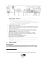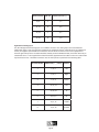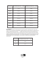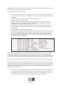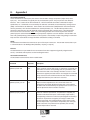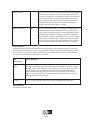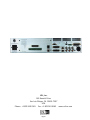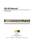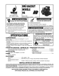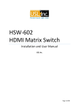
1
Film-Tech
The information contained in this Adobe Acrobat pdf
file is provided at your own risk and good judgment.
These manuals are designed to facilitate the
exchange of information related to cinema
projection and film handling, with no warranties nor
obligations from the authors, for qualified field
service engineers.
If you are not a qualified technician, please make no
adjustments to anything you may read about in these
Adobe manual downloads.
www.film-tech.com
JSD100Manual
CinemaProcessor
USL,Inc.
181BonettiDrive
SanLuisObispo,CA934017397
USA
Phone:+18055490161Fax:+18055490163www.uslinc.com
OneYearLimitedWarranty
USL,Inc.warrantsthateachproductmanufacturedbyitwillbefreefromdefectsinmaterialand
workmanshipundernormalusageforaperiodofone(1)yearafteritspurchasenewfromanauthorized
dealer.Ourobligationunderthiswarrantyislimitedtorepairingorreplacinganyproductorcomponent
whichwearesatisfieddoesnotconformwiththeforegoingwarrantyandwhichisreturnedtoourfactory,
freightpaid,orservicedbyoneofourauthorizedcontractors.Theforgoingwarrantyisexclusiveandinlieuof
allotherwarranties,whetherexpressedorimplied.Suchwarrantyshallnotapplytoanyproductor
component(A)repairedoralteredbyanyoneotherthanUSL,Inc.oranauthorizedservicecontractor;(B)
tamperedwithoralteredinanywayorsubjectedtomisuse,negligenceoraccidentor(C)whichhasbeen
improperlyconnectedinstalledoradjustedotherthaninaccordancewithUSL,Inc.’sinstruction.
Page2
TableofContents
1.
SafetyNotice
2.
RegulatoryCompliance
2.1
2.2EquipmentClass
2.3DisposalandRecycling
3.
SystemOverview
Page
9
4.
Specifications
Page
10
5.
Installation
Page
12
5.1InitialPowerUp
5.2SystemHardwareMounting,GroundingandVentilation
5.3RearPanelConnections
5.4AudioInputConnections
5.5AudioOutputConnections
5.6AutomationInterface
6.
GraphicalUserInterfaceConfiguration
Page
22
6.1GUIInstallation
6.2SetIPUtility
6.3JSD100Configuration
6.4Automation
6.5SystemMonitoring
6.6GUIViewsofMultipleJSD100s
7.
ProductSupport
Page
45
8.
AppendixA–AutomationCommands
Page
46
9.
AppendixB–SystemRestore
Page
48
Page
4
Page
5
Page3
1. SafetyNotice
SafetyNotices
Reviewthefollowingsafetyprecautionstoavoidinjuryandpreventdamagetothisproduct.Toavoid
potentialrisk,usethisproductonlyasspecifiedandonlyforthepurposedescribedintheinstructionmanual.
ToAvoidFireandPersonalInjury:
x Usecorrectpowercable.Useonlythepowercableprovided.EnsurethattheACpoweroutletis
locatedneartheproductandiseasilyaccessible.
x Useacorrectlygroundedpowersource.Thepowersupplyearthgroundisestablishedthroughthe
groundconductorinthepowercable.Toavoidthepotentialofelectricshock,thegroundconductor
mustbecorrect.
x Observesourceratings.Toavoidriskoffireorelectricshock,thepowersourcemustbe100–240
VAC,50–60Hz.
x Donotoperatewithsuspectedfailures.Ifyoususpectthereisdamageormalfunctionwiththis
product,callthefactory.
x Donotattemptrepair.Onlyatrainedfactoryservicepersonisauthorizedtorepairthisproduct.
x Donotoperatethisproductnearheatsources.Thisproductshouldnotbelocatednearheat
sourcessuchasradiators,heatregisters,orstoves.
x Provideproperventilation.Theoperatingtemperaturerangeisbetween0ºCand40ºC.The
humidityrangeisbetween20%and80%,noncondensing.Thecoolingmethodisconvection.
x Keepproductsurfacescleananddry.Disconnectthepowercablefromthepowersourcebefore
cleaning.Donotuseliquidcleanersoraerosolcleaners.Useadampclothforcleaning.
x Donotpushobjectsintoopeningsofthisproduct.Neverinsertobjectsintotheproductthrough
openings.
x Donotoperateinwetordampconditions.
x Donotoperateinanexplosiveatmosphere.
x Inspectthepowercableandallcablespriortouse.Confirmthatthepowercableandother
interconnectingcablesarefreefromdamage.
Page4
2.RegulatoryCompliance
EN609501
TheEN609501standardspecifiesthesafetydesignrequirementsthatreduceoreliminatetheriskof
personalinjurytoboththeproductuserandservicepersonnel.Thisproductisdesignedandtestedtomeet
thestandardsoftheInternationalElectrotechnicalCommission(IEC)EuropeanNormEN609501,IEC609501
(thestandardforinformationtechnologyequipmentincludingelectricalbusinessequipment).
LeRésumédelaSécuritégeneralEuropéen
Examinezlesprécautionsdelasécuritésuivanteséviterlablessureetprévenirledégâtàceproduit.Éviterle
risquepotentiel,utilisezceproduitseulementcommeaspécifiéetseulementcarlebutadécritdansle
manueld’instructions.
ÉviterFeuetBlessurePersonnelle
x UtilisezleCâbleduPouvoirCorrect.Utilisezseulementlecâbledupouvoirfourni.AssurezquelesAC
fontfonctionnerledébouchéestlocaliséprèsleproduitetestaccessiblefacilement.
x UtilisezuneSourceduPouvoirCorrectementFondée.
x LaterredumondedelaProvisionduPouvoirestétablieàtraversleconducteurmouludanslecâble
dupouvoir.Éviterlepotentieldechocélectrique,leconducteurmouludoitêtrecorrect.
x ObservezdesEstimationsdelaSource.Pouréviterrisquedefeuouchocélectrique,lasourcedu
pouvoirdoitêtre220240VAC50Hz.
x N’opérezpasceProduitavecToutesClôturesOuvertesouEnlevez.
x Évitezl’EnsembledecircuitsExposé.N’entreprenezpasouvrirlaProvisionduPouvoirparcequesa
certificationdelasécuritéseraitinvalidée.LaProvisionduPouvoirestunappareilscellénon
réparable.
x N’opérezpasaveclesÉchecsSuspects.Sivoussuspectezilyaledégâtoumalfonctionneravecce
produit,appelezl’usine.
x N’entreprenezpasRéparation.Seulementunepersonneduservicedel’usinecompétenteest
autoriséepourréparerceproduit.
x N’opérezpasceProduitSourcesdelaChaleurProches.Ceproduitnedevraitpasêtrelocalisé
desourcesdelachaleurprochestelqueradiateurs,registresdelachaleur,poêles,ouamplificateurs.
x FournissezVentilationAdéquate.Latempératuredufonctionnementdevraitêtreentre0°Cet40°C.
x L’humiditédevraitêtre20%et80%.Laméthoderefroidissanteestparconvectionetunventilateur
interne.
x GardezlesSurfacesduProduitNettoientetSec.
x Déconnectezlecâbledupouvoirdelasourcedupouvoiravantdenettoyer.N’utilisezpasde
nettoyeurs.liquidesoudenettoyeursdel’aérosolUtilisezuntissuhumidepournettoyer.
x Nepoussezpasd’ObjetsDansOuvrirdeceProduit.
x Jamaisobjetsdel’encartdansleproduitàtraversouvertures.
x N’opérezpasDanslesConditionsMouilléesouhumides.
x N’opérezpasDansuneAtmosphèreExplosive.
x PrévenezleRépandredesLiquidessurlesComposantsduSystème.
x Inspectezlecâbledupouvoirettouslescâblesantérieuràusage.Confirmezquelecâbledupouvoir
etautresinterconnectantcâblessontlibresdedégât.
LeNiveaudelasécurité
L’EN60065niveauspécifieexigencesdudessindelasécuritéquiréduisentouéliminentlerisquedeblessure
personnelleàl’utilisateurduproduitetpersonnelduservice.Ceproduitestconçuetesttestépoursatisfaire
auxniveauxdel’ElectrotechnicalCommissionInternational(IEC)NormEuropéen(EN)60065(LeNiveaupour
MatérieldelaTechnologiedel’InformationquiInclutleMatérieldel’AffaireÉlectrique).
Page5
AllgemeineSicherheitZusammenfassungEuropäisch
ÜberprüfenSiediefolgendSicherheitVorkehrungen,VerletzungzuvermeidenundSchadenzudiesem
Produktzuverhindern.UmpotentiellesRisikozuvermeiden,benutzenSiediesesProduktnurals
vorgeschriebenhatundnurdennderZweckbeschriebinderBedienungsanleitung.
UmFeuerundPersönlicheVerletzungzuvermeiden:
x BenutzenSieKorrektesMachtKabel.BenutzenSienurdasMachtKabel,dasbereitgestelltwurde.
StellenSiesicher,daßderWECHSELSTROMMachtAbflußinderNähevomProduktgefundenwird
undleichtzugänglichist.
x
x
x
x
x
x
x
x
x
x
x
x
x
x
BenutzenSieeineKorrektgeerdetMachtQuelle.DerMachtVersorgungErdeBodenwirddurchden
BodenSchaffnerimMachtKabelgegründet.DasPotentialelektrischenSchockszuvermeidenmuß
derBodenSchaffnerkorrektsein.
BeobachtenSieQuelleKlassen.RisikovonFeueroderelektrischemSchockzuvermeidenmußde
MachtQuelle100sein240VAC5060Hz.
OperierenSiediesesProduktmitIrgendwelchenGehegennicht,diegeöffnetwurden,oderentfernen
Sie.
VermeidenSieUngeschütztenSchaltkreise.VersuchenSie,dieMachtVersorgungzuöffnennicht,
weilseineSicherheitZulassungungültiggemachtwerdenwürde.DieMachtVersorgungisteinnicht
reparierbaresluftdichtverschlosseneGerät.
OperierenSiemitverdächtigtMißerfolgennicht.WennSieverdächtigen,gibtesSchadenoder
FunktionsstörungmitdiesemProdukt,rufenSiedieFabrik.
VersuchenSiekeineReparatur.NureineerzogenFabrikDienstPersonwirdermächtigt,dieses
Produktzureparieren.
OperierenSiediesesProduktNaheHitzeQuellennicht.DiesesProduktsolltekeinenaheHitze
QuellenwieHeizkörper,HitzeRegister,Herde,oderVerstärkergefundenwerden.
StellenSieRichtigeBelüftungbereit.DieoperierendTemperatursolltezwischen0°Cund40°C.Die
Luftfeuchtigkeitsolltesein20%und80%.DieerfrischendMethodeistdurchKonvektionundeinen
innererenFächer.
BleibenSie,ProduktOberflächenreinigenundTrocken.TrennenSiedasMachtKabelvonderMacht
QuellevordemReinigen.BenutzenSiekeineflüssigeReinigeroderAerosolReiniger.BenutzenSie
einenklammenStofffürdasReinigen.
SchiebenSiekeineGegenständeInsÖffnenvondiesemProdukt.NieBeifügungGegenständeins
ProduktdurchÖffnungen.
OperierenSieInNassenoderKlammenZuständennicht.
OperierenSieIneinerExplosivenAtmosphärenicht.
VerhindernSiedasVerschüttenvonFlüssigkeitenaufdieSystemBestandteile.
InspizierenSiedasMachtKabelundalleKabelvorausgehendzuVerwendung.BestätigenSie,daßdas
MachtKabelundandereverbindendKabelfreivonSchadensind.
SicherheitStandard
DerEN60065StandardschreibtSicherheitEntwurfAnforderungenvor,derreduzierenoderdasRisiko
persönlicherVerletzungzusowohldemProduktBenutzeralsauchDienstPersonalausschließen.Dieses
Produktwirdentworfenundwirdgeprüft,umdenStandardsvomInternationalenElectrotechnical
Commissionzuentsprechen(IEC)europäischerNorm(EN)60065(DerStandardfürInformationen
TechnologieAusrüstung,dieElektrischeUnternehmenAusrüstungeinschließt).
2.1
DeclarationofConformity
TheJSD100meetstheintentofDirective89/336/EECforElectromagneticCompatibilityandLowVoltage
Directive73/23/EECforProductSafety.Compliancewasdemonstratedtothefollowingspecificationsaslisted
intheOfficialJournaloftheEuropeanCommunities:
Page6
EN55022:2006ConductedandRadiatedEmissions
x ConductedEmissions
x RadiatedEmissions,ClassALimits
EN55024:1998+A1:2001&A2:2003Immunity
x ElectrostaticDischargeImmunity
x RFElectromagneticFieldImmunity
x PowerLineSurgeImmunity
x ConductedRFimmunity
x PowerFrequencyMagneticFieldSusceptibility
x VoltageDips,ShortInterruptionsandVariations
x EN6100033:1995+A1:2001&A2:2005VoltageFluctuationandFlicker
FCCPart15,SubpartB
ThisequipmenthasbeentestedandfoundtocomplywiththelimitsforaClassAdigitaldevice,pursuantto
part15oftheFCCRules.Theselimitsaredesignedtoprovidereasonableprotectionagainstharmful
interferencewhentheequipmentisoperatedinacommercialenvironment.Thisequipmentgenerates,uses,
andcanradiateradiofrequencyenergyand,ifnotinstalledandusedinaccordancewiththeinstruction
manual,maycauseharmfulinterferencetoradiocommunications.Operationofthisequipmentina
residentialareaislikelytocauseharmfulinterferenceinwhichcasetheuserwillberequiredtocorrectthe
interferenceatuser’sownexpense.
Certifications
x LowVoltageDirective73/23/EEC.
x EN60950InformationTechnology,Video,andsimilarElectronicApparatus.
x IEC60950SafetyRequirements.
x CE,UL,cULSafetyandOverallCompliance.
x VDECertifiedPowerCords
x Pollution:Notintendedforenvironmentswhereconductivepollutantsmaybepresent.
2.2 EquipmentClass
TypeA:Equipmentthatisintendedforconnectiontothebuildingpowersupplywiringvianonindustrial
plugsandsocketsorviaappliancecouplers,orboth.
2.3
DisposalandRecycling
WheelieBinSymbol
TheWheelieBinsymbolisattachedtothisproductincompliancewiththeEUDirective2002/96/EC
onWasteElectricalandElectronicEquipment(WEEE).Itspurposeistodetertheimproperdisposal
ofthisproductandtopromotereuseandrecycling.
ProperDisposal
InconformancewiththeDirective,atendoflifethisproductshouldbeeithersenttoanappropriaterecycling
facilityfordisassemblyandrecyclingorreturnedtothesupplier.Undernocircumstancesshouldthisproduct
bedepositedinalandfillfordisposal.
HazardsofNoncompliance
Electricalandelectronicproductsmaycontainchemicalswhichcanleachintothegroundwaterandcause
healthconcernsthroughcontaminateddrinkingwater.Failuretodisposeofthisproductincompliancewith
theWEEEDirectivemayresultinpenaltiesasdeterminedbylocalordinance.
Page7
PleasecontactyourdealerorUSL,Inc.,withquestionsregardingtheproperdisposalofthisoranyotherUSL
product.USL,Inc.contactinformation:
USL,Inc.
181BonettiDrive
SanLuisObispo,CA934017397
USA
Phone:+18055490161Fax:+18055490163
www.uslinc.com
Page8
3. SystemOverview
TheJSD100cinemasoundprocessorisspeciallydesignedfordigitalcinemaapplications.Lownoiseandlow
distortionprocessingensuresuperbpresentations.Inadditiontotheeightstandardformats,theJSD100
offerstwofullyconfigurableformats.Thetwouserconfigurablebuttonscanbeconfiguredtosupporta
varietyofexistingandfutureformats.Theymayalsobeusedtoduplicateanexistingformatbutatadifferent
faderleveltosimplifydesiredvolumechangesbetweencontenttypes.Thefrontpaneldisplayshowsthe
currentfaderlevel,theformatname(whichisuserconfigurable),andthemeasuredaudioleveloneach
channelofthemainaudiooutput.Thebuiltinbypassaudiocircuitryinsuresthatthepresentationgoesonin
theunlikelyeventofasystemfailure.
TheJSD100is“automationfriendly.”ItfeaturesthestandardDB25parallelautomationinterface,anRS232
(EIA232)interface,andEthernet.TheEthernetinterfaceaccepts10simultaneousTCPconnectionstoallow
controlbyadigitalcinemaserverandotherequipmentwhilesimultaneouslybeingmonitoredoveranother
TCPconnection.
TheGraphicalUserInterfacerunsonWindowsXP®andWindows7®operatingsystems.Itallowsforcomplete
systemconfiguration,monitoring,andfirmwareupdatesoverUSB,Ethernet,orRS232.Systemmonitoring
andfirmwareupdatefunctionsarealsoavailableonastandardwebbrowser.
TheJSD100isalso“diagnosticfriendly.”Thesystemlogsthelast32,000events(formatchanges,level
changes,internaltemperature,lossofAESaudio,etc.)tointernalflashmemory.Logdatacanbereviewedon
theGUIorthewebinterface.Currentoperationalstatus,includingselectedformat,faderlevel,andmeasured
audiooutputlevels,isavailableontheGUIandonthewebinterface.
Apluginmoduleexpandsthestandard8channeldigitalinput(4AESpairs)toa16channeldigitalinput(8AES
pairs).AnotherpluginmoduledecodesDolby®Digital1andProLogicalternatecontentinputs.
TheHIandVI/Noutputsareconfigurableonaperformatbasis.Therearpanelaudiooutputmoduleprovides
eightmainaudiooutputs(servobalancedoutputsthatcandrivebalancedorunbalancedloads).Theoutput
moduleisfieldreplaceabletoallowforupgrades(suchasAESoutputs,moreanalogoutputs,internal
crossovers,etc.).
1
ManufacturedunderlicensefromDolbyLaboratories.DolbyandthedoubleDsymbolaretrademarksofDolbyLaboratories.
Page9
4.
Specifications
Features
AprocessorspeciallydesignedforDigitalCinemaapplications.Lownoiseandlowdistortionprocessing
ensuressuperbpresentations.Inadditiontoeightstandardformats,theJSD100offerstwofullyconfigurable
optionalformatstoaddresssuchdetailsasaudiolevelchangesand3or5stagechannels.Builtinbypass
audiocircuitryensuresthatthepresentationgoeson.
AudioInputs
PAMicrophone–XLR0.7mVsensitivity
CalibrationMicrophone–3.5mmStereoJack0.7Vsensitivitywith10Vpower
NonSyncanaloginput–RCA75mVto4.775V
Auxiliaryanaloginput–RCA300mV
EightChannelanaloginput–DB25300mV
COAX1–RCAPCMandoptionalDolbyDigital®decoding
COAX2–RCAPCMandoptionalDolbyDigital®decoding
TOSLINK–OpticalPCMandoptionalDolbyDigital(R)decoding
AESEBU8Channel4896KHzsamplerates(16channelwithDI80optionalcard)
AnalogAudioOutputsADA
HearingImpaired–UserselectableinputchannelorLCRmix.300mVmonobalanced.
VisualNarration–Userselectableinputchannel(8or16).300mVmonobalanced.
AnalogAudioOutputsBaseModel
EightChannelsBalanced300mVadjustable(L,C,R,LS,RS,SW,LC/BSL,RC/BSR)
AnalogAudioOutputsCrossoverModels(Optional)
ThreechannelBiamp
FivechannelBiamporthreechannelTriamp
CommunicationPorts
DB25PulseAutomation
SerialControl–RS232
USBforLaptopSetup
Ethernet10/100RJ45
FrontPanelInterface
x Elevenbuttons:COAX1,COAX2,TOSLINK,DIGITAL16CH,USER1,USER2,ANALOG8CH,NON/SYNC,
AUX,MIC,andMUTE
x MainFader—010usedformainaudioandbypassaudio
x Frontpaneldisplaysfaderlevelandselectedformat.Bargraphsdisplayoutputlevels
x USBconnector
x PowerswitchandpowersupplystatusLEDs.Turningpoweroffactivatesbypassmode.
FormatSelection
Digital(COAX1,COAX2,TOSLINK,8to16ChannelAESEBU)
Analog(8channel,NonSync,Auxiliary,Microphone)
Option(ConfigurableinSoftware,e.g.,Digital16channelatlowerlevel)
Page10
RearPanelConnectors–MainChassis
x PAMicrophone–XLR
x CalibrationMicrophone–3.5mmStereoJack
x EightChannelAnalog–DB25
x Non/Sync–twoRCAjacks
x AUX–twoRCAjacks
x Hearingimpairedandvisualnarration–pluggablePhoenixConnector
x COAX1andCOAX2–RCAJackswithtransformerinput
x TOSLINK–Optical
x 16channelDigitalAESEBU–DB25andDualRJ45
x RemovableMemoryCard–SDCompatible
x SerialControl–RS232
x PulseAutomationDB25
x 10/100MEthernetRJ45
x DC12Vpowerconnector–5mmwith2.5mmpin
x ACpower–IECsocket
RearPanelInterfaceModule
x BaseUnit–EightChannelAnalog,oneDB25andonePhoenixConnector(20pins)
x OptionalCrossoverModule–TwoDB25andtwoPhoenixConnectors.MainDB25andOptionDB25.
x OptionalAESRBUDigitalOutputModule16to32outputchannels
Processing
x Onethirdoctaveequalizationonthemainchannels
x Parametricequalizersonthesubwoofer
x Synchronizationdelaysforallinputs
x Surrounddelaysforallsurroundchannels
SleepMode
WithanEthernetcommandorpresettimeout,theunitcangointoasleepmode.AnotherEthernet
command,“buttonpress,”orautomationpulsewillwakeuptheunit.
BypassMode
Inanemergencysituation,theJSD100canbeswitchedoff,automaticallyenablingthebypasscircuitry.Front
panelbuttons,LEDs,andfaderwillstillfunction,allowingtheoperationoftheunitinvariousformats.Final
outputisamonophonicsignalfeedtotheleftandrightchannels.Note:The12VDCbypasssupplymustbe
connectedforthisfunctionality.
DynamicRange:Typically105dB
PowerRequirements:100240VAC,50/60Hz,30watts
Dimensions:Standard2Urackmountchassis.
AgencyApprovals:UL,cUL,CEandFCC
Page11
5.
Installation
5.1 InitialPowerUp
AquickpoweruptestoftheJSD100issuggestedbeforemountingitintheequipmentrackandwiringitup.
Thistestcanquicklydetectshippingorotherdamage.
x TurntheACpowerswitchtotheoffposition.
x UsingthesuppliedAClinecordoroneappropriatefortheinstallationlocation(thepowersupplyisa
universalinputsupply100240VAC,50/60Hz),connecttheJSD100totheACline.
x Connectthesupplied12VDCbypasspowersupplytothebypasspowerinputontherearpanelofthe
JSD100andplugitintotheACline.Thefrontpanel“BypassMode”LEDshouldflash,thebypass
powerLEDshouldlight,andoneoftheformatbuttonsshouldlight.
x Presseachoftheformatbuttonsandthemutebutton,oneafteranother.Theappropriatebutton
shouldlight.
x TurnontheACpowerswitch.Thedisplayshouldimmediatelylight,butbeblank.Allthegreenpower
LEDsonthebottomrightofthefrontpanelshouldlight.The“BypassMode”LEDshouldstop
flashing.
x Afterapproximately25seconds,theformatbuttonswillflashandthenasingleformatLEDwilllight.
Thedisplayshouldshowthefaderlevelandtheselectedformat.
x Presseachoftheformatbuttons,verifyingthatthecorrespondingLEDlightsandthatthedisplay
changesaccordingly.NotethattheformatbuttonLEDsfordigitalformatswillflashwhennodigital
inputisprovided.
x PressthemutebuttonverifyingthatitsLEDtoggleseachtimethebuttonispressed.
x Rotatethefaderineachdirectionverifyingthatthefadernumbersonthedisplaychange.
5.2 SystemHardwareMounting,GroundingandVentilation
TheJSD100isdesignedtomountinastandard19inch(482.6mm)rackandistworackunitshigh(3.5inches,
137.8mm).TheJSD100shouldbemountedat“eyelevel”intheequipmentrackforoptimumdisplaycontrast
andvisibility.Werecommendventedpanels(USLpartnumberVP1)aboveandbelowtheJSD100whenever
spacepermits.Mountingtheunitimmediatelyaboveamajorheatproducingcomponent,suchasapower
amplifier,isnotrecommended.EquipmentmountedimmediatelyabovetheJSD100shouldnotbemorethan
9inches(225mm)deeptoinsureadequateairflowthroughtherearventilationslotsontheJSD100.TheJSD
100includesathreepronggroundingplugandathreewirepowercordtoaccommodateasafegroundpath
fromthechassistotheelectricalsystemground.Defeatingthisgroundbyremovingthegroundprongisnot
recommended.
5.3 RearPanelConnections
Asetofcliponferrite“beads”issuppliedwiththeJSD100.ToinsuretheJSD100continuestomeetFCCand
CEradioemissionsrequirements,oneofthesebeadsshouldbeclippedaroundeachcableconnectedtothe
rearpaneloftheJSD100exceptfortheTOSLINK,ACPower,andBypassPowerconnections.
Page12
1.
2.
3.
4.
5.
6.
7.
8.
9.
10.
11.
12.
13.
14.
15.
16.
17.
BypassPowerSupply–12VDCat1.25A.
PowerentryModule–AcceptsIECtypeoflinecordfrompower100240VACsource.Alsocontainsa
500maSloBlo5x20mmfuse.
OutputModule–Swappabletoprovidevariousmainoutputconfigurations.
a) 8ChannelAnalogmoduleprovidessixfixedoutputs(L,C,R,SW,LS,RS)andtwothatcanbe
setupaseitherLC/RCorBSL/BSR.BalancedlinePhoenixandDB25connectorsareprovided.
b) USLLinkAnRJ25connectorthatprovidesanRS485interface.
Ethernet–Communications,selectontheuserinterface.
RS232Connectorforcommunications.
AutomationConnector–Abidirectionalportforreceivingandsendingautomationpulsesbetween
theJSD100andothersystemcomponents.12Controllines,11Statuslinesand+5Vareprovided.
Standardpulsetogroundsystem.
SDCardstoresthesettingsoftheunit.Canalsobeusedtotransfersettingstoanotherunit.
AESconnector(DB25)–DCIcompatible.Channels18arestandard.Channels916requirethe
optionalDI80module.
AESconnectors(DualRJ45s)–parallelconnectionstotheDB25above.
TOSLINKPort–OpticalFiberinputforSPDIF(PCM)oroptionalDolbyDigital®2decoding.
COAX1,COAX2RCAtypeconnectorsforSPDIF(PCM)oroptionalDolbyDigital®decoding.
HearingImpaired/VisualNarrationOutputs.
AUXconnectors–LandRanaloginputs,300mVsensitivity.
NonSync(N/S)connectors–LandRanaloginputs.
RTAmicrophone–TRSconnectorwith+10VontheRing,designedforusewithapoweredelectret
microphone.
8ChannelAnalogInput–Balancedlineinputs.Sixchannelarefixed(L,C,R,SW,LS,RS)andtwocan
besetupaseitherLC/RCorBSL/BSR.
PublicAddressMicrophone–DualconnectorwithXLRandTRSPhoneinthecenter.
5.4
AudioInputConnections
8/16ChannelAESInput
TheJSD100accepts16channelAESaudioiftheoptionalDI80cardisinstalled.Otherwise,theJSD100
accepts8channelAESaudio.Thisinputistypicallydrivenbythedigitalcinemaserver(DCS).TheJSD100
2
ManufacturedunderlicensefromDolbyLaboratories.DolbyandthedoubleDsymbolaretrademarksofDolbyLaboratories.
Page13
includesaDB25FconnectorusingtheDCIpinoutandapairofRJ45connectorsusingtheStudioHubpinout.
Thefirstsixchannelsareassignedspeakersbyindustryconvention.Theremainingchannelscanbeconfigured
bytheuser(i.e.,sourcesforHI/VIN,BSL,BSR,etc.).
x
DB25FAESInput.TheJSD100usestheDCIpinoutforthemultichannelAESdigitalaudioinput.
Cableshouldbetwistedpairswithindividualshieldsand110ohmcharacteristicimpedance.TheUSL
suppliedferriteblockshouldbeclippedontothecableadjacenttotheconnectortocomplywithFCC
andCEemissionrequirements.
AudioChannels AESPair DCIPinout(+,,shield) Speakers
x
1,2
1
24,12,25
L,R
3,4
2
10,23,11
C,SW
5,6
3
21,9,22
LS,RS
7,8
4
7,20,8
9,10
5
18,6,19
11,12
6
4,17,5
13,14
7
15,3,16
15,16
8
1,14,2
RJ45AESInput.TheJSD100usestheStudioHubpinoutforAESoverCAT5orCAT6Ethernetcable.
Thesecablesaretwistedpairandhavetherequiredcharacteristicimpedance.TheUSLsupplied
ferriteblockshouldbeclippedontothecablesadjacenttotheconnectorstocomplywithFCCandCE
emissionrequirements.ThetopRJ45connectorconnectstoaudiochannels1through8.Thebottom
RJ45connectorconnectstoaudiochannels9through16iftheoptionalDI80boardisinstalled.
AudioChannels
AESPair
TopRJ45Pins(+,)
Speakers
1,2
1
1,2
L,R
3,4
2
3,6
C,SW
5,6
3
4,5
LS,RS
7,8
4
7,8
Page14
AudioChannels AESPair BottomRJ45Pins(+,)
9,10
5
1,2
11,12
6
3,6
13,14
7
4,5
15,16
8
7,8
EightChannelAnalogInput
TheJSD100eightchannelanaloginputisonaDB25Fconnector.Theanaloginputsareactivebalanced
(differential)inputs.Theymaybedrivenbybalancedorunbalancedsources.Whendrivenbyanunbalanced
source,thenegativeinputshouldbeconnectedtothelowsideofthesourceatthesourceequipmentto
minimizegroundloopnoise.Thecableshouldbetwistedpairwithindividualshields,evenwhendrivenbyan
unbalancedsource.AUSLsuppliedferriteblockshouldbeclippedaroundthecabletoinsureFCCandCEEMI
requirementsaremet.TheDB25FconnectorusestheTHX®pinoutasspecifiedinthefollowingtable.
ChannelNumber DB25FPINS(+,,shield) Speakers
1
2,14,1
Left
2
8,20,7
Right
3
5,17,4
Center
4
25,12,13
SW
5
23,10,22
LS
6
24,11,9
RS
7
16,3,15
LC/BSL
8
19,6,18
RC/BSR
Page15
TwoChannelAnalogInputs
TheJSD100hastwostereo(twochannel)analoginputs(AUXandNS)onRCAconnectors.Connecttheseto
appropriatesourcesusingRCAcables.Variousstereodecodemethodsareavailableinthesystem
configuration.Theseallowdirectdrivingoftheleftandrightspeakers,addingasynthesizedcenterchannel,
andaddingsurroundchannels.
TwoChannelDigitalInputs
TheJSD100hastwoS/PDIFinputsandoneTOSLINKinput.
x S/PDIFInputs.TwostereodigitalinputsonRCAconnectors.ThesearemarkedCOAX1andCOAX2on
theJSD100rearpanel.ThesearestandardS/PDIF(SonyPhilipsDigitalInterface)inputs.Connect
thesetoappropriatesourceswith75ohmcoaxialcablewithRCAconnectorsoneachend.Aswiththe
otherstereoinputs,variousdecodemethodsareavailable.TheUSLsuppliedferriteblockshouldbe
clippedontothecablesadjacenttotheconnectorstocomplywithFCCandCEemission
requirements.
x TOSLINKInput.ATOSLINKopticaldigitalstereoinputisincludedontheJSD100.Connectthisinput
toanappropriatesourcewithastandardTOSLINKcable.Aswithotherstereoinputs,variousdecode
methodsareavailable.
SingleChannelAudioInputs
TheJSD100hasaPAmicrophoneinputandanRTAmicrophoneinput.TheUSLsuppliedferriteblockshould
beclippedontothecablesadjacenttotheconnectorstocomplywithFCCandCEemissionrequirements.
x PAMicrophoneInput.PlugaPAmicrophoneintothecombinationXLR/¼inchTRSconnector.The
microphoneinputmaybeconfiguredtodrivethemainorthesurroundspeakers.Inaddition,thePA
microphoneinputcandrivetheRTAforroomequalization.
x RTAMicrophoneInput.TheRTAmicrophoneinputcandrivetherealtimeanalyzerforroom
equalization.Thejackisa3.5mmTRSconnectorwiththehighsideofthemicrophoneconnectedto
tipandthelowsidetosleeve.Theconnectorringisdrivenwith+10Vthrough2.2ktopowera
preampinthemicrophone.
5.5 AudioOutputConnections
TheJSD100provideseightmainchanneloutputsplusHIandVI/Noutputs.Alloutputsarebalancedandmay
drivebalancedorunbalancedloads.Whendrivingunbalancedloads,runtwoconductorshieldedcableand
connectthe“–”terminaloftheJSD100outputtothelowsideoftheunbalancedloadattheloadinsteadof
attheJSD100tominimizegroundloopnoise.
MainAudioOutputs
Themainaudiooutputsareonamodulethatcanbereplacedfromtherear,allowingforfutureupgrades.The
mainoutputsdriveaPhoenixconnectorandaDB25M.ThePhoenixoutputterminalsaremarked“Main
Outputs,”andtheDB25Mconnectorismarked“MonitorOutputs.”TheDB25Mtypicallydrivesabooth
monitor,whilethePhoenixterminalsdrivetheauditoriumamplifiersorcrossover.Theseoutputsare
connectedtogetherwithintheJSD100.ThefinaltwochannelscanbeconfiguredintheGUIaseitherBSL/BSR
orLC/RC.TheDB25MconnectorusesthesameTHX®pinoutastheeightchannelanaloginput.TheUSL
suppliedferriteblockshouldbeclippedontothecablesadjacenttotheconnectorstocomplywithFCCandCE
emissionrequirements.
Page16
AudioChannel PhoenixMainOutputPins(+,,shield) DB25MMonitorOutputPins(+,,shield)
Left
1,2,3
2,14,1
Center
4,5,3
5,17,4
Right
6,7,8
8,20,7
SW
9,10,8
25,12,13
LS
11,12,13
23,10,22
RS
14,15,13
24,11,9
BSL/LC
16,17,18
16,3,15
BSR/RC
19,20,18
19,6,18
HI/VINOutputs
TheJSD100hasbalancedHIandVI/Noutputsthatcandrivebalancedorunbalancedloads.Aswithother
outputs,theuseoftwistedpairshieldedcableissuggestedwhethertheloadisbalancedorunbalanced.When
drivinganunbalancedload,connectthe“–”outputoftheJSD100tolowsideoftheunbalancedinputat
thedestinationendofthecabletominimizegroundloopnoise.ThesourceofaudiotodrivetheHIandVI/N
outputsisconfigurableonaperformatbasis.TheVI/NaudiooutputistypicallydrivenbyAESinput16.TheHI
audiooutputcanbedrivenfromAESinputs7or15,orfromamainaudiomix.TheUSLsuppliedferriteblock
shouldbeclippedontothecablesadjacenttotheconnectorstocomplywithFCCandCEemission
requirements.
AudioChannel HI/VINPhoenixConnectorPins(+,,shield)
HI
1,2,3
VI/N
4,5,3
Page17
5.6
AutomationInterface
TheJSD100includesthetraditionalparallelautomationinterfaceplusRS232andEthernet.
ParallelInterface
Pins1through10oftheDB25Fautomationconnectorare“control”pinsthatacceptcontactclosureoropen
collectorpulsestogroundtoselectformats.Onaformatchange,thecorrespondingpinisalsopulsedlow
allowingthisinterfacetodriveotherequipment.Pulsingpin11lowtogglesthemutestate.Pins14through
24are“status”pins.Oneofthepins14through23ispulledlowcontinuouslybytheJSD100toindicatethe
selectedformat.ThesepinscoulddriveLEDswitha470ohmseriesresistortoprovidearemoteformat
indication.TheJSD100pullspin24lowwhenthesystemismuted.Pins1through11areinternallypulledup
to+8.4V.Theyeachsource400uAwhengrounded.Apinneedstobepulledbelow2.6Vfor10msormorefor
theJSD100torecognizeitaslow.Onaformatchange,theJSD100pullstheappropriatepinlowfor500ms.
+5Vat100mAisavailableonpin13todriveexternalLEDsorrelays.Theindividualcontrolandstatusoutputs
cansinkupto150mAwithanopencircuitvoltageof+12VDCforinductiveloadslikerelaysor+24Vfornon
inductiveloads(indicatorlamps,etc.).Pin12isthe“automationreturn.”Usethisasthelowsideofswitches
andindicatorsinsteadofusingchassisground.Itisgroundthrougha10ohmresistortolimitgroundloop
current.TheUSLsuppliedferriteblockshouldbeclippedontothecablesadjacenttotheconnectorsto
complywithFCCandCEemissionrequirements.
Pin
Description
1
Control1.Pulselowtoselectformat1(COAX1).Pulseslowwhenformat1selected.
2
Control2.Pulselowtoselectformat2(COAX2).Pulseslowwhenformat2selected.
3
Control3.Pulselowtoselectformat3(TOSLINK).Pulseslowwhenformat3selected.
4
Control4.Pulselowtoselectformat4(16ChannelDigital).Pulseslowwhenformat4selected.
5
Control5.Pulselowtoselectformat5(User1).Pulseslowwhenformat5selected.
6
Control6.Pulselowtoselectformat6(User2).Pulseslowwhenformat6selected.
7
Control7.Pulselowtoselectformat7(8ChannelAnalog).Pulseslowwhenformat7selected.
8
Control8.Pulselowtoselectformat8(Non/Sync).Pulseslowwhenformat8selected.
9
Control9.Pulselowtoselectformat9(AUX).Pulseslowwhenformat9selected.
10
Control10.Pulselowtoselectformat10(MIC).Pulseslowwhenformat10selected.
11
Mute.Pulselowtotogglethemutestateofthesystem.
Page18
12
AutomationReturn.Returncontrolandstatussignalshere.
13
+5Vat100mAtodriveexternalindicators.
14
Status1.Lowwhenformat1(COAX1)isselected.
15
Status2.Lowwhenformat2(COAX2)isselected.
16
Status3.Lowwhenformat3(TOSLINK)isselected.
17
Status4.Lowwhenformat4(16ChannelDigital)isselected.
18
Status5.Lowwhenformat5(USER1)isselected.
19
Status6.Lowwhenformat6(USER2)isselected.
20
Status7.Lowwhenformat7(8ChannelAnalog)isselected.
21
Status8.Lowwhenformat8(NON/SYNC)isselected.
22
Status9.Lowwhenformat9(AUX)isselected.
23
Status10.Lowwhenformat10(MIC)isselected.
24
MuteStatus.Lowwhenthesystemismuted.
25
Unused.Makenoconnectiontothispin.
RS232Interface
TheRS232interfaceappearsonaDE9Fconnectorontherearpanel.TheconnectoriswiredasaDCEdevice.
AcommandinterpreteracceptsASCIIcommands(describedinAppendixA)overtheRS232andEthernet
interfaces.TheRS232portoperatesat38.4kbps,8N1(8databits,noparity,1stopbit),hardwarehandshake.
Inmostsituations,nohandshakeisrequired,andtheRTSandCTSpinscanbeleftopen.TheUSLsupplied
ferriteblockshouldbeclippedontothecablesadjacenttotheconnectorstocomplywithFCCandCE
emissionrequirements.
Page19
Pin
Description
1
DCD–Internallyconnectedtopins4and6.Doesnotneedtobeconnectedinmostcases.
2
TXD–TheJSD100transmitsdataonthispin.
3
RXD–TheJSD100receivesdataonthispin.
4
DTR–Internallyconnectedtopins1and6.Doesnotneedtobeconnectedinmostcases.
5
GND–Signalground.
6
DSR–Internallyconnectedtopins1and4.Doesnotneedtobeconnectedinmostcases.
7
CTS–TheJSD100holdsofftransmittingdataifthedeviceconnectedtotheJSD100drivesthispinlow.
Datatransmissionisresumedwhenthispinisdrivenhigh.ThepinispulledhighintheJSD100sothe
pincanbeleftopeninmostcases.
8
RTS–TheJSD100drivesthispinlowwhenitisnotreadytoreceivedataanddrivesithighwhenitis
readytoreceivedata.Inmostcasesthispincanbeleftopen.
9
RI–TheJSD100providesacurrentlimited(900mA)+5Vtodriveexternalequipmentonthispin.
EthernetInterface
TheJSD100includesastandard10/100MbpsEthernetinterface.Thesameautomationcommands(described
inAppendixA)areavailableonTCPconnectionstoport10001ontheEthernetinterface.TheJSD100accepts
upto10simultaneousTCPconnections,allowingmultiplecontrolandmonitordevicestobeused.The
Ethernetinterfaceisalsodrivenbyawebbrowser.Systemstatusisavailableoninternallygeneratedweb
pages.UseaCAT5orbetterEthernetcabletoconnecttheJSD100tothecontrolnetwork.TheUSLsupplied
ferriteblockshouldbeclippedontothecableadjacenttotheconnectortocomplywithFCCandCEemission
requirements.
USLLink
TheUSLLinkisanRS485bususedtointerfacetheJSD100tootherUSLdevices.Visitwww.uslinc.comfora
listofUSLLinkcompatibledevices.TheUSLsuppliedferriteblockshouldbeclippedontothecablesadjacent
totheconnectorstocomplywithFCCandCEemissionrequirements.
Page20
Pin
Description
1
Currentlimited(100mA)+5Vtodriveexternaldevices.
2
RS485SignalGround.
3
RS485Data.
4
RS485DataNot.
5
NoConnect.
6
NoConnect.
Page21
6.
GraphicalUserInterfaceConfiguration
SystemConfigurationusingtheGraphicalUserInterface
Thegraphicaluserinterface(GUI)allowsforconfigurationandmonitoringoftheJSD100.
6.1 GUIInstallation
TheGUIrunsunderWindows®XPorWindows®7operatingsystems.InsertthesuppliedCDandfollowthe
onscreeninstructions.
Note:ThefirstreleaseofthedriverpackagewillnotworkonWindows7.ThenewWinUSBdriverisanative
USBinterfacethatisbeingusedinthisGUIapplicationrelease.
USBDriverRemoval
ToremovethepreviousJSD100USBdriverinstallation,theJSD100mustbeconnectedtothecomputerand
byusingDeviceManager,thedriverwillbeuninstalledusingthefollowingstepsbelow:
x
x
x
x
x
PowerontheJSD100andwhenstartupiscomplete,connecttheUSBcabletothecomputer.
Run device manager and locate the “LibUsb Devices” entry and select the USL JSD100 Cinema
Processor.
Rightclickthemousetoopenthepropertiesdialogandthenactivatethe“Uninstall”button.
OnWindows7,checkthedeleteoption,andthenproceedbyactivatingthe“OK”button.
UnplugtheUSBcableandproceedtodriverinstallation.
Page22
USBDriverInstallation
TheJSD100Installation(Setup)programcreatesasubfoldercalled“WinUSB_Drivers”thatwillbeusedfor
loadingthenewWinUSBdriver.
x StartdevicemanagerandthenconnecttheUSBcabletoapoweredonJSD100.
x SelecttheUSLJSD100CinemaProcessorfromthedevicelistandrightclickandselect“Properties.”
x
x
Usethe“BrowsemyComputerforthedriversoftware”optiontoloadtheWinUSBdriver.Notethat
thesearchautomaticallyoptionwillreloadtheoldversionandwillneedtorepeatthedriverremoval
process.
Browseto“C:\ProgramFiles\USL\JSD100\WinUSB_Drivers”andthenproceedtoloadtheselected
driverbyactivationoftheNextbutton
Page23
x
x
Proceedtoloadtheselecteddriverbyselectingthe“Installthisdriversoftwareanyway.”
When the installation completes, the device manager will now display the USL JSD100 Cinema
Processor under the libusb (WinUSB) devices. From the GUI the JSD USB device will appear in the
CommunicationsSettingsdialog.
6.2 SetIPUtility
TheSetIPutilityallowstheusertoconfigurethenetworksettingsontheJSD100.
x ConnectthehostcomputertotheUSBportonthefrontoftheJSD100.TheJSD100shouldappear
undertheUSBDeviceList.ItisidentifiedbywhichUSBportitisconnectedtoonthehostcomputer.
ClicktheJSD100onthefoundlist.
x FillintheIPaddress,subnetmask,andgatewayasdotteddecimalvalues.Press“SetIP”tosavethe
valuesintheJSD100.
Page24
x
FillinthenetworkhostnamefortheJSD100.Thehostnamecanbeupto15characterslongand
cannotcontainspaces.Thehostnamewillbeconvertedtouppercasebeforebeingsaved.Press“Set
Name”tosavethevaluetotheJSD100.
6.3
JSD100Configuration
TheJSD100isconfiguredusingthegraphicaluserinterface(Showninstartmenuas:JSD100DigitalCinema
Processor).TheGUImayconnecttotheJSD100overUSB,RS232,orEthernet.Inmostinstallations,
configurationisdoneoverUSB.WithUSB,itisveryclearwhichJSD100youareconfiguring(theonethatthe
USBcableispluggedinto).NotethatyoucanimportexistingJSD80settingstotheJSD100.SeeFile
Management–Open,below.
TheGUIandtheJSD100providetwosetsofcontrolsandtwodisplays.Forexample,youcanchangethe
formatoneithertheJSD100unitorontheGUIandbothwillreflectthenewvalue.Ifyouopena
configurationfilewhenconnectedtotheJSD100,allthesettingsinthatconfigurationfilearesenttotheJSD
100.WhenyouconnecttoaJSD100,alltheconfigurationsettingsinthatunitareloadedintotheGUI.Itis
quitepossibletooperatetheGUIandcreateconfigurationfileswithouttheJSD100beingconnected.Make
surethenewfileissavedbeforeconnectingtheJSD100sincetheconnectionwillcausethecurrentvaluesin
theJSD100tobeoverwrittenwiththevaluesintheJSD100.WhentheJSD100isconnectedtotheGUIanda
newconfigurationfileopened,thatconfigurationdataiscopiedouttotheconnectedJSD100.
WhentheGUIisstarted,the“OverviewScreen”willbevisible.Thisscreencanshowthestatusofmultiple
JSD100systemsonanetwork.Click“Screen1”tobringupthedetailsofthefirst(andonly,atthispoint)JSD
100.
Page25
Click“CommSettings”andthenthe“USB”tab.Makesure“ConnecttofirstavailableUSBdevice”ischecked
andthenpressOK.Pressthe“Connect”buttontoconnecttotheJSD100.Currentsettingswillbe
downloadedfromtheJSD100anddisplayedontheGUI.Detailedbelowaretheseveralbuttonsarevisible
alongthetopoftheGUI:
FileManagement
Thisgroupofbuttonsdetailedbelowdealswithloadingandsavingconfigurationfilesfromthehostcomputer.
x New.Pressing“New”loadsallconfigurationvariablesintheGUIwiththeirdefaultvalues.Youcan
usethisasastartingpointforconfiguringanewsystem(youcouldalsouseopenDefault.j100,as
describedbelow).Youwillbepresentedwitha“saveas”dialogaskingyoutonamethenew
configurationfile.
x Open.Pressing“Open”allowsyoutoloadanexistingconfigurationfie.UseDefault.j100toloadthe
factorydefaults.Youcanthenrevisethesettingsandsavethemunderanotherfilename.Notethat
youmayspecifyeitheraJSD100orJSD80configurationfileunder“filetype.”IftheJSD100is
replacinganexistingJSD80,usetheJSD80GUItosavetheconfigurationfileifitisnotavailableon
thecomputeryou’reusing.Then,withtheJSD100GUI,opentheJSD80configurationfile.Common
data,suchasequalization,willbeloadedintotheJSD100.
x Save.The“Save”buttonpromptsyouforthefilenameunderwhichtheconfigurationdataistobe
saved.DatacanberestoredtothisoranotherunitusingtheOpenbutton.
Communications
ThisgroupofbuttonssetscommunicationsparametersbetweentheGUIandtheJSD100andallows
connectionstobesetupandtakendown.
x Connect.TheGUIconnectstotheJSD100specifiedintheCommSettingsdialogoverthespecified
link.
x Disconnect.TheGUIdisconnectsfromthecurrentlyviewedJSD100.
Page26
CommSettings.PressthisbuttontoconfigurethecommunicationslinktotheJSD100.TheJSD100can
communicatewiththeJSD100overEthernet(TCP/IP),USB,orRS232.Clickontheappropriatetabfor
thisunit.
TCP/IP.Check"Displayautomaticallydetectednetworkdevices"togetalistofJSD100unitstheGUI
canfindonthenetwork.Anydeviceeverfoundislisted(theydonotdisappeariftheyhavenotbeen
heardfrominawhile).Selecttheappropriateunitfromthelistorclick"ManualAdd"tospecifyanIP
addressforaJSD100.Usethe"Remove"buttontoremoveadisplayedunitfromthelist.Oncethe
desiredunitisselected,pressOKtoexitthedialog.
USB.SelectthistabtoconnecttotheJSD100usingUSB.Whenthehostcomputerisconnectedtothe
JSD100USBport,theJSD100shouldbelistedunderthedevicelist.Ifthe"ConnecttofirstavailableUSB
device"ischecked,thefirstdevice(andprobablytheonlydevice)onthelistwillbeselected.Ifitisnot
checked,selecttheappropriatedevice,andthenclickOK.
RS232.SelecttheCOMporttheJSD100isconnectedto,andthenclickOK.
UnitSettings
Thisgroupofbuttonshandlesafew“systemwide”systemconfigurationsettingsandbackingupthose
settings.
x DateandTime.ThisbuttonsetsthetimeandtimezoneinformationintheJSD100.TheJSD100
itselfonlyusestimeofdayinlogging.Further,alllogentriesaremadeinUTC.Whenviewed
throughtheGUI,logdataincludesthetimeinUTC,thetimeattheJSD100(JSDTime),andthetime
attheGUI(GUITime).Theuseofthesethreetimezonesallowsforsimplecomparisonofdevicelogs,
evenwhenthedevicesareinmultipletimezones.TheDateandTimedialogisdividedintotwo
sections.ThetopportionshowsthedateandtimeattheGUI,asreportedbytheoperatingsystem.
ThebottomportionofthedialogboxdealswiththedateandtimeattheJSD100itself.SettheTime
ZonefieldtotheoffsetfromUTCforstandardtimeinthetimezonewheretheJSD100islocated.If
daylightsavingstimeisobservedattheJSD100location,checkthecorrespondingcheckbox.Note
thatthischeckboxindicateswhetherdaylightsavingstimeiseverobservedinthislocation,not
whetheritiscurrentlyineffect.Forexample,youwouldcheckthecheckboxinCalifornia,but
uncheckitinArizona.Fillthenexttwofieldswiththeabbreviationsforstandardtimeanddaylight
savingstimeinthetimezonewheretheJSD100islocated.Thedaylightsavingstimeabbreviation
willnotbeusedifthedaylightsavingstimeobservedcheckboxisunchecked,butyoumaywanttofill
itinanyway.ClickingOKtransmitsthedatatotheJSD100.TheinternalclockissettoUTCbasedon
theOStimeandoffset.TheothervaluesarestoredintheJSD100sotheycanbereadlaterwhenthe
JSD100prepareslogs.
Page27
USTimeZone
UTCOffset
StandardTimeAbbreviation
DaylightSavingsTimeAbbreviation
Alaska
9:00
AKST
AKDT
Central
6:00
CST
CDT
Eastern
5:00
EST
EDT
Hawaii
Aleutian
10:00
HAST
HADT
Mountain
7:00
MST
MDT
Pacific
8:00
PST
PDT
Note:Worldwidetimezonesmaybeviewedatthefollowingwebsites:
http://www.timeanddate.com/library/abbreviations/timezones/
http://en.wikipedia.org/wiki/List_of_time_zones_by_UTC_offset
x
ChannelConfig.TheJSD100containsprocessingcircuitryforbothLC/RCandBSL/BSRaudio
channels,butonesetortheotherisconvertedtoanalogtodrivetheamplifiers.Selectthe
appropriatesettingbasedonhowtheauditoriumiswired(withstage(LC/RC)orex(BSL/BSR)
amplifiersandspeakers.
x
Headroom.Theheadroomsettingadjuststhesystemgainsothenominallevelisaspecifiednumber
ofdBbelowthedigitalclippinglevel(0dBFS).Generally,headroomissetat26dB.Ifseveralbandsof
equalizationaresettohighlevelsofboost,youmaywishtoincreasetheheadroomtoavoidclipping.
x
Backup.PressingthisbuttonwritesthecurrentconfigurationtotheSDorMMCcardpluggedin
behindtheremovablepanelontherearoftheJSD100.Ifthecoverisremoved,youwillseeared
LEDtotheleftofthecardlightasthecardiswritten.AbackuptotheSDcardcanfailifnocardis
present,ifthecardiswriteprotected,orifthecardisnotformattedcorrectly(FAT16orFAT32).The
datawrittenonthecardisaseriesofcommandsinatextfile(JSD100.CFG).IfaJSD100needstobe
swappedout,theSD/MMCcardcanbemovedfromtheoldunittothenewunittocopyalltheold
settingstothenewunit.ToloaddatafromtheSD/MMCcard,holddownbuttons9and10(AUXand
MIC)whenturningtheJSD100mainpowerswitchon.Continuetoholdthebuttonsdownuntilthe
displaysays“LoadingFromSDCard.”Thedisplaywillshowtheprogressoftheloadandthenreturn
tothenormaldisplay.
MainFader
Thecurrentmainfaderlevelcanbeviewedandchangedusingtheslider.Theseareequivalenttothefront
panelmainfaderknobanddisplay.Thefaderleveldisplayalsoshowsasmallbargraphthatdisplaysthe
measuredoutputleveloneachchannel.
FrontPanelView
BelowtheabovedescribedbuttonsisaviewoftheJSD100frontpanel.WhenconnectedtotheJSD100,this
viewduplicatesthelookofthefrontpanel.Inaddition,thebuttonscanbepressedtochangeformatormute
Page28
thesystem,justasonthefrontpanel.TheLEDabovetheformatbuttonlightswhenthatformatisselected.It
flashesiftheformatisadigitalformatandnodigitalsignalispresentontheselectedinput.
Tabs
TheremainderoftheGUIwindowcontainstabsthatdividetheremainingconfigurationdataintological
groups.Eachtabwillbediscussedinsequence.
x Summary.Thesummarytab(viewshownbelow)givesabroadviewoftheJSD100andits
installation.TheTheaterInformationfieldsmaybechangedasneeded.Theothersectionsofthis
screencannotbechangedthroughthesummarytab.
x
x
ComponentInformation.ThePICfirmwareversionidentifiesthefirmwareversionintwoofthe
microcontrollersandthecircuitboardrevisionofthemaincircuitboard.Inthesamplescreenabove,
thefirstDindicatesthisisboardrevisionD.The100924istherevisionofthemainprocessor
firmware.The100325istherevisionoftherearpanelprocessorfirmware.Thistabalsoshowsthe
versionsofthefirmwareforeachofthetwodigitalsignalprocessorsandtheversionfortheGUI
softwareitself.Eachoftheseversionnumberscanbecomparedwithlaterupdatestodetermineif
thelatestfirmwareisalreadyinstalled.
NetworkInformation.ThisisthenetworkinformationthatwassetwiththeJSD100SetIPUtility,
discussedpreviously.
FormatsTab
The“Formats”taballowsthesettingof“PerFormat”configuration.Thesesettingsapplyonlytoaspecific
format.Thetypeofsettingsavailablevariesbyformattype.Theavailablesettingsforeachformatarelisted
belowalongwithdetailsofthesettings.Selecttheformatthatistobeconfiguredusingtheformatbuttons
ontheGUIortheJSD100frontpanel.
Page29
Format
Settings
Coax1
InputName,EnablePreset,PresetLevel,InputDelay,BackSurroundSource,EQSet,
DecodeOptions
Coax2
InputName,EnablePreset,PresetLevel,InputDelay,BackSurroundSource,EQSet,
DecodeOptions
TOSLINK
InputName,EnablePreset,PresetLevel,InputDelay,BackSurroundSource,EQSet,
DecodeOptions
Digital16Channel
InputName,EnablePreset,PresetLevel,InputDelay,BackSurroundSource,EQSet,HI/VI
Source
User1
InputName,EnablePreset,PresetLevel,InputDelay,BackSurroundSource,EQSet,Input
Select,HI/VISource,DecodeOptions
User2
InputName,EnablePreset,PresetLevel,InputDelay,BackSurroundSource,EQSet,Input
Select,HI/VISource,DecodeOptions
Analog8Channel
InputName,EnablePreset,PresetLevel,BackSurroundSource,EQSet,HI/VISource
Non/Sync
InputName,EnablePreset,PresetLevel,BackSurroundSource,EQSet,InputTrim,
DecodeOptions
AUX
InputName,EnablePreset,PresetLevel,BackSurroundSource,EQSet,InputTrim,
DecodeOptions
Mic
InputName,EnablePreset,PresetLevel,BackSurroundSource,EQSet,InputTrim,Mic
Phase
x
x
x
x
InputName.Thenamethatisshownonthedisplayandloggedwhenaparticularformatisselected
canbesetbytheuser.TypeameaningfulnamefortheformatintheInputNamefield.
PresetLevel.Ifpresetisenabled,theJSD100willadjustthemainfaderleveltothepresetlevelset
here.Ifthepresetisnotenabled,theJSD100willadjustthemainfadertothelevellastusedonthis
format.Withapreset,levelscanbeadjustedduringnormaloperationusingthefrontpanelfader,
butwillreturntothepresetlevelwhentheformatisselectedagain.Withoutthepreset,thelevelwill
returntothelevelthatparticularformatwaslastadjustedto.
InputDelay.Aseparateinputdelaysettingisavailableforeachformattoenableprecise
synchronizationoftheaudiowiththeprojectedimage.
BackSurroundSource.Theaudiosourceforthebacksurroundspeakerscanbeconfigured
independentlyforeachformat.Thesesourcesarefurtherdescribedinthetablebelow.
Page30
BackSurround
Source
Description
LS/RS
Thebacksurroundspeakersaredrivenbythesurroundspeakers.BSLisdrivenbyLS.
BSRisdrivenbyRS.ThissettingresultsinanLshapedsurroundwheretheleft
surroundcontinuesdowntheleftwalltotheleftsideoftherearwallofthe
auditorium.
EX
Bothbacksurroundspeakersaredrivenwith0.5(LS+RS).Thisissimilartoaderived
centerspeaker.
CH7/8
Thebacksurroundspeakersaredrivenbydiscretechannels7and8fromthedigital
16channeloranalog8channelsource.Channel7drivesBSL.Channel8drivesBSR.
AES11/12
ThebacksurroundspeakersaredrivenbyAESchannels11and12fromthe16
channeldigitalinput.NotethattheseinputsareonlyavailableiftheoptionalDI80
boardisinstalledintheJSD100.AES11drivesBSL.AES12drivesBSR.
x
x
EQSet.TheJSD100allowsdifferentformatstousedifferentequalizationscurves.FourEQsetsare
available.Eachsetallowsfullequalizationofalltheaudiochannels.Choosewhichequalizationsetto
useforthisformat.
DecodeOptions.Twochannelsourcescanbedecodedouttoseveralchannels.Theseoptionsare
availableondigitalandanalogtwochannelformats,suchasCOAX1,COAX2,TOSLINK,NON/SYNC,
andAUX.
DecodeOption
Description
L_R
Thetwochannelsourcedrivesjusttheleftandrightspeakers.
L_C_R
Theleftandrightchannelsofthesourcedrivetheleftandrightspeakers.Thecenter
speakerisdrivenwith0.707timesthesumoftheleftandrightchannels.Thesubwooferis
drivenwiththecenterchannelafterpassingthroughan80Hzlowpassfilter.
SimpleMatrix
ThefrontspeakersaredrivenwiththesamesignalsasL_C_R,describedabove.The
surroundspeakersaredrivenwith0.707timesthedifferencebetweenleftandright
(0.707(LR)).
ActiveMatrix
ThisoptionisonlyavailableifaDI84boardisinstalledintheJSD100.Iftheinputisdigital
andencodedwithDolbyDigital®(AC3),thesignalisdecodedto5.1.Ifthesignalisnot
digitalorisnotencodedwithDolbyDigital®,thesignalisdecodedto5.1usingDolbyPro
Logic®decoding.IfnoDI84boardisinstalled,thesignalisdecodedasL_R.
Page31
x
Equalizer.TheJSD100equalizerallowsthefrequencyresponseoftheJSD100tobeadjustedforthe
acousticsoftheroom.Theequalizerincludespresetsforaflatresponse,a"peaktopeak"response,
a"zigzag"response,andan"XCurve."Youwouldusuallystartequalizationfromtheflatresponseor
theXCurveresponse.Thepeaktopeakandzigzagresponsesareonlyusedtoprovideaquickcheck
oftheequalizer.NotethattheXCurvebuttondoesnotautomaticallyequalizetheroom.Instead,it
setstheequalizertoanXCurveresponse.Sincetheroomisnotflat,adjustmentswillhavetobe
madefromthesesettingstoprovidethedesiredcurve.
Usingtheinternalpinknoisegeneratorandtheinternalrealtimeanalyzer(RTA),theequalizeris
adjustedsotheRTAshowstheresponsespecifiedastheXcurveinSMPTE202M1998.Thecurve
callsforaflatresponsebetween63Hzand2kHzwiththelevelfallingoffatthelowandhighends.
ThetablebelowlistsidealXcurvelevelsbasedonthenumberofseatsintheauditorium.Formore
details,consultSMPTE202M1998.
XCurveResponseindB(SMPTE202M1998)
NumberofSeats
Frequency
(Hz)
30
150
500
1000
1500
2000
40
2
2
2
2
2
2
50
1
1
1
1
1
1
63–2k
0
0
0
0
0
0
Page32
x
x
x
2.5k
1
1
1
1
1
1
3.15k
2
2
2
2
2
2
4k
2
2.5
3
3.5
4
4.5
5k
3
3.5
4
4.5
5
5.5
6.3k
3
4
5
6
7
8
8k
4
5
6
7
8
9
10k
5
6
7
8
9
10
12.5k
7
8
9
10
11
.12
16k
9
10
11
12
13
14
RTAChannelSelectButtons.ChannelselectbuttonsarealongthetopoftheRTAwindow.These
selectwhichspeakerthepinknoisegeneratorisdrivingandwhichchanneltheequalizercontrolsare
adjusting.
RTASettings.WhenthemousecursorisoverthedisplayareaoftheRTA,anotherrowofsettings
becomesvisible(asshownabove).UsetheSourcebuttontoselectwhetherthecalibrateorPA
microphoneinputisbeingusedtodrivetheRTA.Thecalibratemicrophoneinputisonthe3.5mmTRS
connectorontherearpanel.ThePAmicrophoneinputisonthecombinationXLR¼inchTRS
connector.UsetheZoombuttonstoenlargeorreducethetextwithintheRTAdisplayarea.Usethe
dB/stepselectortoadjusttheverticalresolutionasrequiredtogetallbandsonscreenwhile
providingthebestverticalresolution.Makeinitialadjustmentswithafastdecaytime.Thefastdecay
timeprovidesafasterupdate,butalessstabledisplay.Asyoucloseinonthefinaladjustmentofthe
equalizer,increasethedecaytimetowardsmaximumtoprovideastabledisplayandprecise
indicationoftheequalization.Adjustthegaincontrolasrequiredtoplacethemidbandsignallevelat
0dB.
EQCopy.NotethattheequalizeradjustmentsadjusttheEQsetthatisselectedforthecurrently
selectedformat.YoucanhittheformattabtoquicklyviewwhichEQsetiscurrentlybeingcontrolled.
TheCopybuttoncopiestheEQsettingsforaparticularaudiochannelinanyEQsettoanother
channelinanyEQset.Sincethedifferentaudiochannelstypicallyrequireapproximatelythesame
equalization,onechannelcanbesetupandthencopiedtootherchannelsasastartingpoint.Those
channelsarethenfinetunedasrequired.
Page33
x
x
x
x
x
Pressthe“Copy”button.TheEQCopydialogopens.
SelecttheSource“EQSet”.
Clickthe“+”buttontotheleftoftheEQSetsymbolinthelowerleftportionofthewindow.The
iconwillexplodetotheviewshownabovewhereeachaudiochannelisvisible.
ClickonthespeakercorrespondingtothechannelthatisthesourceoftheEQcopy.Forexample,if
youwanttocopytheleftchannelequalizationtotherightchannel,clicktheleftspeaker.“Select
ChannelDestination”willappearinthedestinationareaofthewindow.
Selectthe“EQSet”destination(oftenthesameasthesource)andthechanneldestination.ACopy
buttonwillappear.ClicktheCopybuttontocopytheequalizationfromthesourcechanneltothe
destinationchannel.Notethatyoucannotcopyachanneltoitselfandyoucannotcopyafullband
channeltotheLFE(LowFrequencyEffectsorsubwoofer)channel.
Press“Close”toclosethecopywindow.
x
ChannelEqualizationProcedure
Asuggestedprocedureofequalizingachannelislistedbelow.Yourtheatermayuseamodifiedordifferent
procedure.
x PositiontheRTAmicrophoneintheauditoriumasspecifiedbySMPTE202M1998(about2/3ofthe
waybackfromthescreenand2/3ofthewayfromasidewalloftheauditorium).Themicrophoneis
normally1.0to1.2meters(3.3to4.0feet)fromthefloor,or“earlevel”foratypicalaudience
member.
x PlugthemicrophoneintothePAorCALmicrophoneinputoftheJSD100.SettheRTAinputtothe
appropriatemicrophoneinput.
x Setthefrontpanelfaderlevelto7.0.
x Turnamplifiergainsallthewaydown.Movethegaincontrolontheequalizerallthewaydown.This
adjuststhe“outputtrim”onthechannelthatisbeingadjusted.Thereareseparateoutputtrimsfor
eachaudiooutput.
x Selectthechanneltobeequalized,pinknoise,andgeneratortosendpinknoiseouttheappropriate
outputoftheJSD100.
Page34
x
SlowlyincreasethepoweramplifiergaintofullwhilewatchinganSPLmeterattheRTAmicrophone
position.Donotincreasethelevelabove85dBSPL.
x PushtheXCurvebuttonontheequalizertosettheinitialEQsettings.TheXCurvebuttonadjuststhe
equalizertotheSMPTE202M1998Xcurvewithoutconsiderationofauditoriumacoustics.Itisa
suggestedstartingpointtoadjusttheroomequalizationtomatchtheXcurvespecifiedinthe
preceedingtable.
x Adjustthegaincontrol(outputtrim)ontheequalizeruntilameasuredsoundlevelof85dBSPLor
82dBSPLforsurroundchannelsispresent.
x AdjusttheRTAgaintoputthemidbandlevelat0dB.
x AdjusttheequalizercontrolstoputeachfrequencybandwithinthelimitsoftheXCurveasshownon
thetableabove.Asdiscussedabove,thedecaytimeshouldbeincreasedformorestableandprecise
measurementasyoucloseinonthefinalequalization.
x Turnoffthegenerator.
x CopytheequalizersettingstothenextchanneltobeequalizedusingtheCopybutton,asdescribed
above.Thenrepeattheprocessforthenextchannel.
LFEEqualizationProcedure
TheLFEorsubwooferchannelusesaparametricequalizerinsteadofagraphicequalizer.WhentheLFEis
selectedintheEqualizerwindow,theparametricequalizeradjustmentsbecomevisible.
x Aswiththeotherchannels,startwiththeamplifiergainallthewaydownandtheequalizergainall
thewaydown.
x Slowlybringuptheamplifiergaincontroltofullwithoutexceeding85dBSPL.
x AdjusttheequalizergaincontrolupuntiltheRTAshowsthesubwooferatthesamelevelasthemid
bandfrequencies(0dB).
x Adjusttheparametricfilterfrequencytothecenteroftheworstpeakordipinthefrequency
response.
x SettheQto4,andthenadjustthelevelcontroltotakeoutthediporpeak.TheQcanbeincreasedto
narrowthecorrectionorreducedtomakethecorrectionwider.Adjustthelevel,frequency,andQ
forthebestlowfrequencyresponse.
x SelecttheoutputtabandclickGeneratorunderthecenterchannelslider.Atthispoint,thepinknoise
generatorshouldbedrivingboththeLFEandcenterchannels.Selecttheequalizertabagain.
x AdjusttheLFEgainandmakeminoradjustmentstotheLFEparametricfiltertogetasmooth
frequencyresponseoverthetransitionintotheLFEfrequencyrange.Itmaybenecessarytoflipthe
phaseoftheLFEspeaker.ThephasecanbechangedontheOutputstabusingtheInvertbutton
undertheLFEoutputlevelcontrol.
x Finally,ontheequalizertab,adjusttheLFEgainsotheLFEis10dBabovethemidrangefrequencies.
OutputsTab
Theoutputstabprovidesamethodoftrimmingtheoutputlevelofeachaudiochannel,mutingthechannel,
invertingthephase,ordrivingitwithagenerator(pinknoise,tone,oratonesweep).Thesecontrolsare
generallysetonebyonefromtheEqualizertab.Thistabmakesallthesettingsvisibleatonce.
GlobalTab
Globalsettings,thosethatdonotchangewithformatorEQset,aresetordisplayedhere.Underthistab,the
currenttimesettings,sleepsettings,status,andsurrounddelaycanbeobserved.Inaddition,thesleep
settingsandsurrounddelaycanbeset.
Page35
x
x
x
x
UnitTime.Thetimesettingsintheunitcanbeobservedinthissectionofthetab.Thesesettingsare
setusingtheDate&Timebuttonatthetopofthescreen.TheUnitTimedataincludesthecurrent
UTCvalueintheJSD100realtimeclock,thetimezoneoffsetfromUTCforstandardtime,the
abbreviationsforstandardanddaylightsavingstime,andwhetherdaylightsavingstimeisobserved
atthislocation.
SleepSettings.TheJSD100includesasleeptimer.Thetimerisresettoitstimeoutvalueonany
formatchange,anyfaderlevelchange,oranyaudiooutputabove20dB(referencedto300mVRMS).
If,forexample,thesleeptimeoutissetto1hour,thesystemwillgotosleep1hourafterthelast
formatchange,levelchange,oraudio.Whenthesystemgoestosleep,powerconsumptionis
decreasedfromabout18Wtoabout7.5W.Thesystemwakesuponaformatchange,alevelchange
oraspecificcommandoverEthernet(SeeAppendixA).Audiopresencewillnotwakethesystemup
sincetheaudiocircuitryisshutdownduringsleep.Thecurrentsleeptimervalueisshown.Theunit
willgotosleepinthedisplayednumberofhoursandminutes.Tosetthesleeptimeout,keyinthe
numberofhoursandminutesorusethearrowstochangetheSleepTimeoutvalue.Oncethevalueis
entered,pressSetTimeouttosavethevalueintheJSD100.Ifsleepisnottobeused,presstheMax
TimeoutbuttonandthenpressSetTimeout.
UnitStatus.ThisportionoftheglobaltabshowsthetemperaturewithintheJSD100,whetherthe
optionalDI80andDI84boardarepresent,andthestatusofAESinputs.TheDI80boardisrequired
for16channeldigitalinput.Withoutit,theAESinputis8channels.TheDI84boardisrequiredto
decodeDolbyDigital®andDolbyProLogic®fromtwochannelinputs.WhentheGetAESStatus
buttonispressed,theAESChannelStatusindicatorsareupdated.Greenindicatestheparameteris
true.Redindicatesitisfalse.Grayindicatesitcannotbedetermined.
SurroundDelay.ThesurrounddelaycanbeadjustedontheGlobaltab.Thesurrounddelayisset
basedonthelengthandwidthoftheauditorium.Formulastodeterminethesurrounddelaywith
auditoriumLengthandWidthinmetersandfeetareprovided.
SurroundDelayUsingMeters.WithLengthandWidthoftheauditoriuminmeters,thesurround
delay,inms,shouldbe(L/3)(W/6)+20.
SurroundDelayUsingFeet.WithLengthandWidthoftheauditoriuminfeet,thesurrounddelay,in
ms,shouldbesettoL(W/2)+20.
Page36
x
LoggingTab.TheJSD100includesextensivelogging.TheleftsideofthescreenshowstheGUIlog.It
showsGUIactivity,suchasconnectionstoJSD100unitsandotheractivities.Therightsideofthe
screenshowstheUnitLogforthespecificJSD100.
x
TheJSD100holdsalogofthelast32,768events.Eventsincludelevelchanges,formatchanges,
remoteconnectionsbytheGUIorotherdevices,etc.PresstheGetLatestbuttontogetthe100most
recentlogentries.PresstheGetAllbuttontogetthefulllogfromtheJSD100.
ThelogshowstherecordnumberintheJSD100log,theUTCtimeoftheevent,the“JSDTime”ofthe
event,andthe“GUITime”oftheevent.TheJSD100storesalllogeventsinUTCtime.Whenthelog
eventsaredisplayedbytheGUI,thetimeattheJSD100iscalculatedbasedonthesettingsentered
usingthe“Date&Time”buttonontheGUI.TheGUIappliesthetimezoneoffsetforwheretheJSD
100islocated,determinesifthedaylightsavingstimeisobservedwheretheJSD100islocated,and
whetherdaylightsavingstimeiscurrentlyineffect.Basedonthisdata,theGUIcalculatesand
displaysthetimeoftheeventattheJSD100.Thenameofthetimezone(PDTinthesample)is
showninthecolumnheadertohelpidentifythetime.TheGUIalsodoesasimilarcalculationto
display“GUItime.”ThatisthetimetheeventoccurredattheGUIlocation,whichmaybeseveral
timezonesawayfromwheretheJSD100islocated.
Thelogshowsthesourceoftheevent(internal,USBPort,frontpanel,TCP9,etc.).Whenadevice
connectstotheJSD100overEthernet,theconnectionandtheIPaddressarelogged.Lateractions
canbetiedtoaspecificIPaddressbylookingbackthroughthelogforthelastconnectiontothatTCP
port.TheJSD100supports10simultaneousTCPconnectionsonTCP9throughTCP0.
PressingtheSavebuttonsavesthecurrentlydisplayedlogdataasatabdelimitedtextfile.Thisfile
canbeimportedintoaspreadsheetorviewedwithatexteditor.
SoftwareUpdateTab.ThefirmwareinthemainprocessorandtheDigitalSignalProcessors(DSPs)in
theJSD100canbeupdatedthroughtheGUIoverEthernetorUSB.Therightsideofthescreenshows
thecurrentfirmwareversions.Theleftsideofthescreencontainscontrolstodoafirmwareupdate.
Page37
FirmwareisusuallydeliveredinaSoftwarePackagethatincludesnewversionsofthecodeforeach
DSPandthemainprocessor(PIC).Wesuggestmakingtheupdatesinthisorder:DSP2,DSP1,PIC.
Lookattheversionsofeachpieceofcodeinthesoftwarepackage.Ifoneoftheversionsisalready
installedintheJSD100,thatportionoftheJSD100doesnotneedtobeupdated.
x
x
Selectthedevicetobeupdated:DSP2,DSP1,orthePIC.PresstheBrowsebuttontoselectthefileto
bedownloadedtotheJSD100.PresstheDownloadbutton.Duringthedownload,thefrontpanel
LEDsontheJSD100willflash.AfteradownloadofthePIC(themainprocessor),theJSD100will
resettostartexecutingthenewcode.TheGUIwilldisconnectatthattime.
PICFirmwareRestore.IfadownloadofthePICfirmwaretotheJSD100isinterrupted,theJSD100
maybeleftinoperable.Torestoretheoriginalfirmware,turnofftheJSD100,pressbuttons4and6
onthefrontpanel(Digital16ChannelandUser2),thenturnthepoweronwhilecontinuingtohold
thebuttonsdownuntilthefrontpanelLEDsstartflashing.Whentheystopflashing,thefactory
installedfirmwarehasbeenrestored,andtheJSD100willrestart.
DiagnosticsTab.ThistabprovidesdiagnosticsthathelpUSLpersonnelindebuggingthesystem.You
maybeinstructedbyUSLtoperformvariousfunctionsonthistabtodebugproblemsinthe
installation.TheterminalsectionofthisscreencanbeusedtotestJSD100commands,suchasthose
anautomationcouldsend.Theimagebelowshowsacoupleautomationcommandsbeingsenttothe
JSD100.Clickthemousecursorintheterminalarea,andthentypecommands(tabdelimitedand
terminatedwithacarriagereturn).SeeAppendixAformoreinformationonautomationcommands.
x
DisconnectAndSave.Allthesettingsthathavebeenmadeuptothispointarecurrentlydetermining
howtheJSD100operates.However,thesesettingswillnotberestoredonapowercycleunlessthe
disconnectbuttonispressedandasaveisrequested.ItisVERYIMPORTANTthatthechangesyou’ve
justmadearesavedintheJSD100.InthedialogboxthatappearsafterpressingDisconnect,press
SaveChangestosavethesechangestononvolatilememoryintheJSD100.Ifyoudonotsavethe
changes,theywillremainintheJSD100untilthepoweristurnedoff.Thepreviouslysavedsettings
willthenberestored.Atthispoint(priortodisconnecting),youmayalsowanttobackthesettingsup
totheSDcardbypressingBackup,asdescribedpreviously.
Page38
x
SystemOperation.TheJSD100iscontrolledbythedigitalcinemaserverinmostinstallations.
Controlisalsoavailablefromthefrontpanel.
Page39
1.
1.
2.
3.
4.
5.
6.
7.
8.
9.
10.
11.
12.
13.
14.
15.
USBConnectorforcommunications.Selectontheuserinterface
COAX1–RearPanelRCAtypeconnectorforPCMoroptionalDolbyDigital®3decoding.
COAX2–RearPanelRCAtypeconnectorforPCMoroptionalDolbyDigital®decoding.
TOSLINK–AnopticalfiberconnectionforPCMoroptionalDolbyDigital®decoding.
16CHANNELDIGITAL–AESBalancedlineinputs.Thechannels18arestandard.Channels916
requiretheoptionalDI80module.
USER1–allowstheselectionandconfigurationofanyinputandanysettings.
USER2–allowstheselectionandconfigurationofanyinputandanysettings.
8CHANNELANALOG–Balancedlineinputs.Sixchannels(L,C,R,SW,LS,RS)arefedthroughtheunit
withappropriatedelaysandEQ.ThetworemainingchannelsmaybeconfiguredasLC/RC(stage
delay)orBSL/BSR(backsurround).
NONSYNC–2ChannelAnalogBalancedLineInput.Inputsensitivityandlevelmaybeadjusted.
AUX–2ChannelAnalogBalancedLineInput.Inputsensitivityisfixedbutinputlevelmaybeadjusted.
MIC–PublicAddressBalancedlineinput.Inputsensitivityandlevelmaybeadjusted.
MUTE–mutesalloutputs.
Display–indicatestheFaderlevel,formatinputandbargraphdisplayoftheoutputsignallevels.
PowerIndicatorLEDs–displaysstatusofpowersupplyvoltages.
PowerSwitch.
Fader–Controlstheoverallvolumeofallthechannels.
FrontPanel
Theinputselectbuttonschoosewhichinputistodrivetheauditoriumspeakers.TheLEDabovethebutton
willlightwhenthatinputisselected.Iftheselectedinputisdigital,butnodigitalsignalisavailable,theLED
willflash.
Pressingthe“mute”buttoncontrolsmutingoftheauditoriumspeakers.TheLEDabovethebuttonislitwhen
thesystemismuted.
Thedisplayshowsthecurrentmainfaderlevel,theuserdefinednameofthecurrentlyselectedformat,anda
bargraphshowingthemeasuredaudiolevelsoneachoutput.
TheMainFaderadjuststheoutputvolume.Asitisadjusted,thedisplayisupdatedtoshowthenewfader
level.Notethatthefaderlevelwillgenerallychangeonaformatchange.Iftheformathasapresetfader
level,thefaderwillchangetothatlevelwhentheformatisselected.Iftheformatdoesnothaveapreset
faderlevel,thefaderwillchangetothelevellastusedonthatformat.Thelastusedfaderlevelmemorizes
“onthefly”faderadjustments.Iftheoperatorturnsdownthefaderduringthetrailersandthenswitchesto
3
ManufacturedunderlicensefromDolbyLaboratories.DolbyandthedoubleDsymbolaretrademarksofDolbyLaboratories.
Page40
Digital16forthemovie,thefaderlevelwillreturntothenewlysetlevelfortrailersthenexttimethatformat
isselected.
ThemainpowerswitchturnstheJSD100onandoff.Whenthepowerisoff,theJSD100entersbypassmode
ifthebypasspowersupplyispluggedin.ThebypasssystemintheJSD100usescompletelyseparate
electronicstogenerateamonauralsignalthatdrivestheleftandrightmainaudiooutputs.Thefrontpanel
switchesandfaderoperatethesameinbypassandnormalmodes.Allinputsexceptmicrophoneareavailable
inbypassmode.
6.4
Automation
TheJSD100acceptsexternalcontrol(suchasautomation)overEthernet,RS232,andaparallelautomation
port.
x TheJSD100acceptsupto10simultaneousTCPconnectionsonport10001.Adigitalcinemaserver
cansendcommandstotheJSD100throughaTCPconnection.Thecommandstructureisdescribedin
AppendixA.
x TheJSD100acceptscommandsovertheRS232port.Thehardwareinterfaceisdescribedinthe
installationsection.ThecommandsaredescribedinAppendixA.
x TheJSD100acceptsandgeneratesparallelautomationpulsesontheDB25Frearpanelautomation
connector.Pulsingpin1togroundisthesameaspushingthefirstbuttononthefrontpanel(COAX
1).Pulsingpin2togroundisthesameaspushingthesecondbutton.Theparallelautomation
interfaceisdescribedinmoredetailinSection5.6.
6.5 SystemMonitoring
AlargenumberofJSD100systemscanbemonitoredsimultaneouslyoverEthernet.Multipleunitscanbe
monitoredandcontrolledusingtheGUI.Multipleunitscanbemonitored,butnotcontrolled,usingaweb
browser.
6.6
GUIViewofMultipleJSD100s
TheGUImainscreenprovidesanoverviewofseveralJSD100systems.Systemsarenormallybrokeninto
groupsrepresentingtheaters.EachgroupcontainstheindividualJSD100systemsforeachauditorium.
Page41
AddingGroups
Createagroupforeachtheater.ThegroupisacollectionofJSD100s,oneineachauditorium.
x Clickthe“Groups”buttonatthetopofthescreen.
x Click“Add”.Youwillbepromptedtoenterthenameofthenewgroup.
x Click“OK”whenyouhavefinishedaddinggroups.
AddingAuditoriums
x Clickthe“Auditoriums”button.TheAddAuditoriumdialogboxwillappear.
x
x
x
x
Click“Add”toaddanauditorium.
Thenameoftheauditoriumcanbechangedasdesired.
Selectthegroupfromthepreviouslydefinedlistofgroups.
Click“Change”underCommunicationsSettingstosettheIPaddressoftheJSD100inthis
auditorium.
Page42
x SelecttheIPaddressoftheJSD100fromtheautodetecteddevicelistifitispresent.Ifnot,press
“ManualAdd”andthenkeyintheIPaddressoftheJSD100inthisauditorium.
x Press“OK”toexitCommSettingsandOKtoexitAuditoriums.
Oncegroupsandauditoriumsaredefined,theGUIshowsasummaryviewofeachJSD100onthenetwork.
Thesummaryviewincludestheselectedformat,thefaderlevel,andcommunicationssettings.Clickingonthe
summaryviewboxbringsupthedetailedviewofthatparticularJSD100whereallcontrolsareavailable.
WebViewofJSD100
TheJSD100includesawebserver.ThewebservercanbeusedtoviewthecurrentstatusoftheJSD100,
viewtheJSD100log,anduploadnewfirmware.
Page43
TheStatusPageshowsthecurrentfaderlevel,thecurrentformat,andabargraphshowingtheaudiooutput
levels,auditoriuminformation,andnetworkinformation.
TheLogPageshowstheJSD100systemlog.
x Thefirstcolumnshowsthelogrecordnumber(0to32,767),theUTCtimeoftheevent,thesourceof
theevent,thetypeofevent,andtheeventdescription.Thelogentriesbelowshowthesystembeing
poweredup.
x Record2showsthecontentsofacoupleprocessorregistersafterreset.
x Record3showsthecauseofthereset.
x Record4showsthatthesystemconfiguration(equalizationandothersettings)wereloaded.
x Record5showsthecurrentinternaltemperature.Thetemperatureisloggedwhenthesystemis
powereduporwhenthetemperaturechanges10degreesC.
x Record6showsthattheformatselectedonpowerupwasadigitalinput,butnodigitalsignalwas
availableatthattime.Whenadigitalsignalappearsortheformatischanged,theclearingofthe
errorislogged.
x Record7showsafaderchangefromthefrontpanel.
x Record8showsaTCPconnectionfrom192.168.1.70.Suchalogentryistypicallyaconnectionbythe
GUIorfromautomation.NotethattheIPaddressislogged,associatingthisIPaddresswithTCP9.
LatereventsfromTCP9originatedatthisIPaddress.Record9showsTCP9beingdisconnected,so
192.168.1.70hasdisconnectedfromtheJSD100.Usethepreviousandnextlogpagelinkstostep
backwardandforwardthroughthelog.
TheConfigurationPageshowsthesameauditoriumdataandnetworkdataasthestatuspage.Whenfirst
accessingtheconfigurationpage,youwillbeaskedforausernameandpassword.Theusernameisadmin.
Thedefaultpasswordisultra.Tochangethepassword,enterittwiceatthebottomoftheconfigurationpage,
thenpressthe“SaveNewPassword”button.TheConfigurationPagehasalinktotheUpdateFirmwarepage.
TheUpdateFirmwarePageallowsthefirmwareinthetwoDSPsandthemainprocessor(PIC)tobeupdated.
FirmwareisusuallydeliveredinaSoftwarePackagethatincludesnewversionsofthecodeforeachDSPand
themainprocessor(PIC).Wesuggestmakingtheupdatesinthisorder:DSP2,DSP1,PIC.Lookattheversions
ofeachpieceofcodeinthesoftwarepackage.IfoneoftheversionsisalreadyinstalledintheJSD100,that
portionoftheJSD100doesnotneedtobeupdated.Thecurrentlyinstalledfirmwareversionisshownonthe
Updatebuttonforeachprocessor.
x Selectthedevicetobeupdated:DSP2,DSP1,orthemainprocessor(PIC).Pressthe“Browse”button
toselectthefiletobedownloadedtotheJSD100.Pressthe“Update”button.Duringtheupdate,
thefrontpanelLEDsontheJSD100willflash.Afteranupdateofthemainprocessor,theJSD100
willresettostartexecutingthenewcode.Thebrowserwilldisconnectatthattime.
Page44
7.
ProductSupport
USLproudlystandsbehindourproducts.Wearereadytoanswerquestionsabouttheinstallationor
operationoftheJSD100.Applicationnotes,manuals,andotherdocumentsareavailableonourwebsiteat:
www.uslinc.com.Youmaycontactusby:
x Phone:+18055490161
x Email:[email protected]
x Youmayfileasupportticketat:www.uslinc.com/support
USLisinterestedinyourcomments.Pleasefeelfreetocontactuswithanycommentsorsuggestions.
Page45
8.
AppendixA
AutomationCommands
ThesecommandsareusedtoquerythestatusoftheJSD100orchangeitsoperation(adjustlevel,select
input,etc.).Thecommandsaretypicallysentbyanautomationsystem.TheymaybesentoverRS232or
Ethernet.Thisisasubsetofthefullcommandset.Thefullcommandsetincludescommandsforadjust
equalization,etc.CommandsarenotechoedbytheJSD100.Commandsareterminatedbyacarriagereturn
(0x0d).Commandsaretabdelimited.Thereneedstobeatabcharacter(0x09)betweenthecommandand
thefirstparameter,thenanothertabbeforethesecondparameter,etc.TheJSD100respondstoevery
command.Responsesarealsotabdelimitedandareterminatedwithacarriagereturn.Allcommandsare
lowercaseandarecasesensitive.Note:Everycommandgeneratessomesortofresponsethatmustbe
pickedupbythecommandsender.FailuretopickuptheseresponsescancausebuffersintheJSD100orthe
hosttofill,possiblyhaltingcommunications.Iftheresponseisnotneeded,asimple"eatgarbage"routinethat
loopsuntilthereceivebufferisemptyshouldbecalledbeforesendingacommand.
RS232
TheJSD100isaDCEdevicethattransmitsonpin2ofthe9pinDconnector.TheJSD100receivesdataonpin
3.Communicationsisat38.4kbps,8N1(8databits,noparity,1stopbit).
Ethernet
TheJSD100listensonport10001forTCPconnectionsfromotherequipment(typicallyadigitalcinema
server).CommandsandresponsesarethenexchangedinASCII.
AutomationCommandList
TheAutomationCommandListshownintablebelow:
Command
Response
Description
jsd100.sys.fader700
700
Setsorreadsthecurrentfaderlevel.Ifaparameterisprovided,the
mainfaderissettothecorrespondinglevel.Theparameteristhe
faderleveltimes100.Inthisexample,thefaderissetto7.0.Ifno
parameterissupplied,thefaderlevelisnotchanged.Thecommand
alwaysreturnsthecurrentfaderleveltimes100.Ifthecommand
changedthefaderlevel,thenewlevelisreturned.
jsd100.sys.fader_rel50
50
Makesarelativeadjustmenttothecurrentfaderlevel.The
parameteristherelativeadjustmenttimes100.Intheexample,
thefaderlevelwasdecreasedby0.5(perhapsfrom7.0to6.5).The
relativeadjustmentthatwasmadeisreturned.
jsd100.sys.input_mode4
4
Selectsorreadstheinputformat.Ifaparameterissupplied,the
JSD100isswitchedtothisinput.Intheexample,inputmode4,
correspondingtobutton4onthefrontpanel(Digital16Channel)is
selected.Ifnoparameterissupplied,nochangeismadetothe
currentinputmode.Thecommandalwaysreturnsthecurrently
selectedinputmode.Ifaparameterwasprovided,thenewinput
modeisreturned.Ifnoparameterwasprovided,thecurrently
selectedinputmodeisreturned.
Page46
jsd100.sys.mute1
1
SetsorreadsthecurrentmutestatusoftheJSD100.Ifthesupplied
parameteris1,thesystemismuted.Ifthesuppliedparameteris0,
thesystemisunmated.Ifnoparameterissupplied,themutestatus
ofthesystemremainsunchanged.Thecommandalwaysreturns
thecurrentmutestatusofthesystem.Ifthecommandincludesa
parameter,thenewmutestatusisreturned.Ifnoparameteris
supplied,thecurrentmutestatusisreturned.
jsd100.sys.sleep120
120
Setsorreadsthesleeptimer.Ifnoparameterisprovided,theJSD
100returnsthenumberofminutesuntilitwillgotosleep.This
timerisresettothesleeptimeoutvalueonoutputaudiopresence,
formatchange,orfaderlevelchange.Ifaparameterisprovided,
thesleeptimerissettothespecifiednumberofminutes.Ifthereis
outputaudio,aformatchange,orafaderlevelchange,thesleep
timerissettoitstimeoutvalue.Iftheparametertothiscommand
isnonzeroandthesystemissleeping,thesystemwillwakeup.
DCSConfiguration
AdigitalcinemaserverisnormallyconfiguredtosendcommandstotheJSD100overEthernetorRS232at
appropriatetimesduringcontentplayout.TheuserneedstoconfiguremacrostosendcommandstotheJSD
100.Serversvaryinhowcontrolcharacters(suchastabandcarriagereturn)areentered.Thetablebelow
listsafewserversandhowcontrolcharactersareentered.
DCS
Manufacturer
ControlCodeEntry
Dolby
AutomationcommandsarecurrentlyonlysupportedoverRS232,notEthernet.InShow
Manager,onthe"serialautomation"systempage,thereisa"termination"fieldwhere
youcanputbytecodestobeaddedtotheendofeachcommand.Bydefaultthe
systemincludes"\0A"(linefeed)inthisfield,butyoucanchangeit"\0D"(carriage
return)oranyothersequence.Thiswillterminateeachautomationstring.Toinserta
tabinanautomationstring,use“\09”.
Doremi
Use"\r"tosendacarriagereturnattheendofastringdefinedforarawdevice.
ManualRevisions
SecondEdition,October2010.
Page47
9.
AppendixB
SystemRestore
TheJSD100hasseveralmethodsofrecoveringfromanunlikelyfailure.Thesearedetailedbelow.
BypassMode
WhentheJSD100mainpowerswitchisoffandthebypasspowersupplyispluggedin,independentbypass
circuitrycreatesamonosumoftheselectedanalogordigitalinputaudioandroutesittotheleftandright
outputs.AquickwayofrecoveringfromasystemfailureistoturntheJSD100off.
RestoreFactoryFirmware
Ifafirmwareupdateofthemain(PIC)processerisinterrupted,itispossibletoleavethesysteminoperable.To
restorethefactoryinstalledfirmware,turnofftheJSD100,thenholddownbuttons4and6(Digital16
ChannelandUser2)whileturningthepowerbackon.ThefrontpanelLEDswillstartflashing.Releasethe
buttonswhentheLEDsstartflashing.WhentheLEDsstopflashing,thesystemwillrestartwiththeoriginal
firmware.Theinterruptedfirmwareupdatecanthenberepeated.
LoadConfigurationfromSDCard
TheSDcardisusedasa"personalitymodule"intheJSD100.ShouldaJSD100bereplaced,allthesaved
settingsfromtheoldunitcanbeeasilyloadedintothenewunitwithouttheuseofacomputer.These
settingsweresavedduringtheinitialconfigurationusingtheBackupbuttonontheGUI.Torestorethe
settingstoanewJSD100,insertthecardfromtheoldunit(behindtheremovablecoverontherearpanel)in
thenewunit.WiththeJSD100off,holddownbuttons9and10(AUXandMIC)downwhileturningonthe
power.Continuetoholdthebuttonsabout30secondsuntilthedisplaysays"LoadingfromSDcard."The
configurationwillbeloadedandcopiedtotheinternalnonvolatilememory.TheJSD100isnowconfigured
thesameasthepreviousunit.Anyerrors(missingcard,missingfile,etc.)arereportedonthedisplay.
Page48
AdditionalJSD100Manualsmaybeviewed/downloadedat:
www.uslinc.com
Page49
USL,Inc.
181BonettiDrive
SanLuisObispo,CA934017397
USA
Phone:+18055490161Fax:+18055490163www.uslinc.com
Page50