1
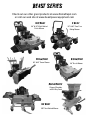
SNOW BLOWER by Owner’s Manual This manual contains important safety instructions for the gasoline engine powered snow blower models: 30SB, 36SB, 45SB READ SAFETY WARNINGS AND OPERATING INSTRUCTIONS CAREFULLY. SAVE THIS MANUAL. Need Help? Parts, Service, and Technical Assistance call: (919)-550-3221 Monday-Friday 8:00AM-5PM EST www.beastpowerequipment.com DO NOT RETURN THIS SNOW BLOWER TO THE STORE! When you call the help-line you will need to have the following information: Date of Purchase: _______________________ Location of Purchase: _______________________ Serial # - Snow Blower: _______________________ *Serial number is located on engine block below the starter. Snow blower and engine life is extended greatly by performing frequent lubrications, oil changes and regular maintenance. To protect your investment perform routine maintenance. Snow BEAST 30SB, 36SB, 45SB Copyright© 2012 by GXi Outdoor Power, LLC. All rights reserved. No part of this publication can be reproduced or distributed without prior written permission of GXi Outdoor Power, LLC Clayton, NC 27520 USA. DEK is a registered trademark of GXi Outdoor Power, LLC GXi Outdoor Power, LLC reserves the right to discontinue or change specifications or design at any time without notice and without incurring any obligation whatsoever. The information and specifications included in this publication were in effect at the time of approval for printing. This manual contains important safety instructions for Snow Blowers READ SAFETY WARNINGS AND OPERATING INSTRUCTIONS CAREFULLY SAVE THESE INSTRUCTIONS. This owner’s manual is considered a permanent part of the snow blower and should remain with the snow blower if resold. V8.10.25.12 Snow BEAST Snow Blower BEAST SERIES Check out our other great products at www.HomeDepot.com or visit our web site at www.beastpowerequipment.com Z-Beast Turf Beast 36” & 54” Walk Behind Finish Mower 54” & 62” Zero-Turn Riding Mower Snow Beast Brush Beast 36” & 45” Snow Blower Brush Master Chipper/Shredder with 2-Way Feed The Beast 100” Tow Behind Mower 36” Brush Mower Snow BEAST 30SB, 36SB, 45SB Contents Safety Information and Warnings ......................................................................... 1 Preparation Safety Precautions ............................................................................2 Operation Safety Precautions ................................................................................3 Safety Decals ........................................................................................................... 5 Product Specifications ...........................................................................................6 Control Panel and Snow Blower Components.................................................... 7 Missing Parts Request Form ...................................................................................8 Assembly Instructions ............................................................................................9 Operating Instructions Starting the Engine......................................................................................... 14 Operating Instructions....................................................................................15 General Maintenance.....................................................................................18 Maintenance Schedule ..................................................................................19 Service Adjustments Adjusting Augers/Impeller Cable ..................................................................20 Adjust/Check Drive Cable ..............................................................................20 Adjusting Shift Rods........................................................................................19 Adjust/Replacing Drive and Augers/Impeller Belts ...................................21 Adjusting Discharge Chute Deflector ..........................................................22 Changing Friction Wheel................................................................................22 Replacing Headlight Bulb ..............................................................................22 Storage Instructions ..............................................................................................23 Troubleshooting ......................................................................................................24 Replacement Parts .................................................................................................26 Limited Warranty and Service ............................................................................. 31 About the Snow Beast Manual Congratulations on the purchase of your new Snow Beast commercial snow blower. We at GXi Outdoor Power are confident that this snow blower will provide excellent performance, outstanding quality, and great durability when operated and maintained as directed in this manual. 1. This manual contains assembly, operating, safety, adjustment, maintenance, and troubleshooting instructions. BEFORE OPERATING YOUR SNOW BLOWER, CAREFULLY READ THIS MANUAL IN ITS ENTIRITY. 2. This owner’s manual is considered a permanent part of the snow blower. It must be available to all operators and/or person(s) servicing the snow blower. Should the snow blower be resold, this manual must remain with the snow blower. 3. All information, illustrations, and specifications contained in this manual were in effect at the time of the publication. GXi Outdoor Power reserves the right to add, delete or modify specifications and/or designs without notice. 4. If you ever have questions in regards to the operation, maintenance or safety of your snow blower, please contact GXi Parts & Service, LLC at 1-919-550-3221. V8.10.25.12 Snow BEAST Snow Blower Snow BEAST Safety Information and Warnings Safety Information Emission Control System Information 30SB, 36SB, 45SB Training The U.S. and California Clean Air Acts EPA and California regulations require all manufacturers to furnish written instructions describing the operation and maintenance of emission control systems. The following instructions and procedures must be followed in order to keep the emissions from your engine within the emission standards. Maintenance, replacement, or repair of the emission control devices and systems may be performed by any engine repair establishment or individual, using parts that are ‘‘certified’’ to EPA standards. 1. Read, understand, and follow all instructions on the machine and manual(s) before attempting to assemble and operate. 2. Operator must be familiar with all controls, their operations, and how to stop the engine and disengage the controls quickly. 3. Never allow children to operate this machine. 4. Never allow adults to operate this machine without proper instruction. 5. Exercise caution to avoid slipping or falling, especially when operating the machine in reverse. 6. Keep area of operation clear at all times. Safety Label Locations Safety labels are located on your snow blower to warn you of potential hazards. Read them carefully. If a label comes off or becomes hard to read, contact GXi Parts and Service, LLC for a replacement. Operator Responsibility It is the owner’s responsibility that all operators and mechanics must be trained and read this manual before operating the snow blower as well as being physically able individuals. They should be instructed about safe operating and mechanical procedures. If they can not read or understand English, it is the owner’s responsibility to explain all safety operating instructions. The owner or operator is responsible for accidents or injuries occurring to themselves, other people or property. Potential misfortunate incidents can be prevented by the owner/user. WARNING WARNING! Do not use your BEAST snow blower to carry passengers. Keep bystanders, helpers, pets and children at a safe distance from the machine while it is in operation. Inspect the area where the equipment is to be used and remove all objects such as rocks, toys, and wires which can be thrown by the machine causing serious injury or death. WARNING Snow Blower Inspection For your safety, inspect the snow blower before each use. Before you begin your inspection, be sure the following conditions are met: the snow blower should be on a level surface, with the ignition switch off, the key removed, and the augers disengaged. Also, disconnect the spark plug wires from the spark plugs and ground them against the engine to prevent inadvertent starting. V8.10.25.12 Wear appropriate clothing including hard hat, safety glasses and hearing protection. Long hair, loose clothing or jewelry may get tangled in moving parts. Snow BEAST Snow Blower 1 Snow BEAST Preparation Safety Precautions Preparation—Safety Precautions 1. Inspect the area where the equipment is to be used and remove all objects such as rocks, mats, and wire which can be thrown by the machine causing serious injury or death. 2. Disengage all clutches and shift to neutral before starting the engine. 3. Disengage all control levers before starting the engine. 4. Use extension cords and receptacles as specified by the manufacturer for all units with electric drive motors or electric starting motors. 5. Use a grounded three-wire extension cord when using the electric start option. 6. People, pets, and most importantly children must not be near the area being cleared. Do not operate the snow blower in their presence. 7. Never operate snow blower with damaged guards, shields or covers. 8. All users of the snow blower must be alert and pay attention to safety alerts, symbols, and safety signs. Gasoline and other fuels—Safety Precautions Use extra care when handling gasoline and other fuels as they are flammable and vapors can explode. 1. Only use gasoline approved containers for storage and keep out of reach from children. 2. Do not fill fuel tank completely full. Overfilling may result in fuel leakage. Leave a reasonable amount of space for fuel to expand. 3. If fuel is spilled, do not start the engine. Move the snow blower away from the area, wipe up the spill thoroughly and wait until fuel vapors have evaporated before starting engine. 4. Keep the nozzle in contact with the rim on the fuel tank or container opening at all times, until refueling is complete. Do not use nozzle lock-open device. 5. Do not fill gasoline containers or equipment inside a vehicle or on a truck/trailer bed. 6. Always place gasoline containers on the ground away from your vehicles prior to filling. 7. Never remove gas cap or add fuel when engine is running or the engine is hot. 8. Avoid prolonged breathing of gasoline vapors. 9. Never refuel or drain the machine indoors. V8.10.25.12 30SB, 36SB, 45SB 9. Be sure to inspect snow blower before each use. 10. Check the controls and shields to make sure that they are functioning properly before operating. Do not operate if any are damaged or missing. 11. Never attempt to make any adjustments to the snow blower while it is running. 12. Adjust the collector housing height to clear gravel or crushed rock surfaces. 13. Wear appropriate clothing including hard hat, safety glasses and hearing protection. Long hair, loose clothing or jewelry may get tangled in moving parts. 14. Do not operate without wearing adequate winter clothing. Wear footwear that will improve footing on slippery surfaces. 15. Allow snow blower to adjust to outdoor temperature before starting the engine. 10. Keep face away from nozzle and gas tank opening. 11. Keep gas and other fuels away from skin and eyes. If fuel is spilled on clothing, change clothing immediately. 12. Never use the mouth to siphon gas. 13. Never refuel the snow blower until all moving parts on the snow blower have stopped. 14. Never smoke when handling fuels and stay away from an open flame where fumes can be ignited by a spark. 15. Gasoline is harmful or fatal if swallowed. DANGER DANGER: GASOLINE IS HIGHLY FLAMMABLE AND EXPLOSIVE. Do not add fuel while the engine is running or is hot. Keep open flames, sparks, and heat away from the fuel and store fuel in containers specifically designed for that purpose. ADD FUEL OUTDOORS ONLY. IF THE FUEL IS SPILLED, DO NOT START THE ENGINE. Manually push the snow blower away from the spill and wipe up immediately. Snow BEAST Snow Blower 2 Snow BEAST Operation Safety Precautions Equipment Operation—Safety Precautions 1. Do not operate the engine in a confined space where dangerous carbon monoxide fumes can collect. Carbon monoxide is odorless, tasteless, and can be fatal. 2. Never operate the snow blower without good visibility or light. 3. Exercise extreme caution when operating on or crossing gravel drives, walks, or roads. Stay alert for hidden hazards or traffic. 4. Never operate the snow blower with defective guards or shields, or without the safety devices securely mounted in place and functioning properly. 5. Be aware of discharge and never direct discharge of material toward people or areas where property damage can occur. Keep children and others away. 6. Do not change the governor settings or over speed the engine. 7. Do not overload the machine capacity by attempting to clear snow at too fast a rate. 8. Always stop the engine when you leave the snow blower, even for a moment. 9. To help reduce fire hazard, keep the engine and the area around the engine free of grass, leaves or any other type of foreign material. 10. Beware of any sharp edges. For safety always wear gloves when performing augers/impeller maintenance activities 11. If lightning is seen or thunder is heard in the operators vicinity, do not operate machine. Instead find shelter, as lightning may cause injury/death. 12. After striking a foreign object, stop the engine, remove the wire from the spark plug, thoroughly inspect the snow blower for any damage, and repair the damage before restarting and operating the snow blower. 13. If machine starts to vibrate or function abnormally, stop the engine immediately and check for cause. Vibration is generally a warning of trouble. V8.10.25.12 30SB, 36SB, 45SB 14. Keep hands and feet away from augers/ impeller . This product is capable of amputating hands and feet. 15. Be alert and slow down when making turns. Also look left, right, and behind before changing directions and reversing to be sure there is a clear path. 16. Never operate snow blower at high transport speeds on slippery surfaces. 17. Never operate snow blower under the influence of alcohol and drugs. 18. Use care when loading or unloading the machine into a trailer or truck. 19. Use care when approaching blind corners, shrubs, trees, or other objects that may obstruct vision. 20. Always disengage power to augers when not in use or transported. 21. Never listen to music with headphones/ earphones while operating the snow blower. 22. Use extreme caution when operating on slopes. 23. Never touch a hot engine or muffler. 24. Use caution when operating on gravel surfaces. 25. Only use attachments and accessories that are approved by BEAST. 26. When starting the engine pull the cord slowly until some resistance is felt before using full force. 27. Always have a good grip on the handles and never run while operating the snow blower. 28. Stop the engine whenever you leave the operating position, before unclogging the augers/impeller or discharge chute, and when making any repairs, adjustments or inspections. 29. When cleaning, repairing or inspecting the snow blower, stop the engine and make certain the augers/impeller and all moving parts have stopped. Disconnect the spark plug wire and keep the wire away from the plug to prevent someone from accidentally starting the engine. Snow BEAST Snow Blower 3 Snow BEAST Operation Safety Precautions Clearing A Clogged Chute—Safety Precautions 1. SHUT THE ENGINE OFF! 30SB, 36SB, 45SB Do NOT over-prime the engine. Pressing the primer bulb more than 3x could result in flooding the carburetor making the engine hard to start or cause fuel to leak from the carburetor inlet. 2. Wait at least 10 seconds to be sure the augers have stopped rotating. 3. Always use a cleanout tool and never your hands. 4. Ground the spark plug when clearing if hands get close to the augers/impeller. IMPORTANT! The snow blower belts are adjusted to ensure the augers/impeller stop turning within five (5) seconds of releasing the impeller control lever. If you are making any belt adjustments whatsoever, for your safety and the safety of others around you, you must ensure the belts are readjusted to achieve this design specification. DANGER: Do not bypass, modify, alter or disconnect the safety system. Make sure that the safety interlock system is fully operational each time before operating the machine. GASOLINE IS HIGHLY FLAMMABLE AND EXPLOSIVE. FUEL LEAKS, A LOOSE FUEL TANK, OR A LOOSE FUEL VALVE CAN LEAD TO SEVERE INJURY OR DEATH. DO NOT OPERATE THIS SNOW BLOWER IF ANY COMPONENT OF THE FUEL SYSTEM IS LOOSE OR LEAKS GASOLINE! Before setting up your SNOW BEAST snow blower, disconnect the spark plug wires from the spark plugs and ground them against the engine to prevent inadvertent starting. This step should be taken as a precaution whenever you are working on this machine. Check engine oil level before each use. Maintain oil level between run marks on the dipstick, and change oil according to the maintenance schedule to maximize product life. Before attempting to use your snow blower, make sure you are familiar with all of the components and have read the manual. Need Help? Parts, Service and Technical Assistance call: (919)-550-3221 Monday-Friday 8AM-5PM EST www.beastpowerequipment.com V8.10.25.12 Snow BEAST Snow Blower 4 Snow BEAST Safety Decals 30SB, 36SB, 45SB Safety Decal Identification The labels shown below are located on your snow blower to warn you of potential hazards and provide you with important safety information. If these decals become difficult to read or are missing from the snow blower, please contact GXi Parts & Service, LLC at (919)-550-3221 or www.beastpowerequipment.com for a replacement. V8.10.25.12 Snow BEAST Snow Blower 5 Snow BEAST Feature Product Type Clearing Path Engine Torque Engine Start Speed Control Deck Type Discharge distance Impeller Auger Discharge Chute Fuel/Capacity Chute control Product Specifications 30SB Snowblower 30” 302cc 15.9 ft.lbs 120V Electric Start and recoil 6 fwd, 2 rev All Steel 40’ 16” 2 Stage 16” serrated 6” Unleaded gasoline/1.32 GAL Crank Models 36SB Snow blower 36” 420cc 20.7 ft.lbs 120V Electric Start and Recoil 6 fwd, 2 rev All Steel 40’ 16” 2 Stage 16” serrated 6” Unleaded gasoline/1.32 GAL Crank 30SB, 36SB, 45SB 45SB Snowblower 45” 420cc 20.7 ft.lbs 120V Electric Start and Recoil 6 fwd, 2 rev All Steel 40’ 16” 2 Stage 16” serrated 6” Unleaded gasoline/1.32 GAL Crank * Product Specifications may change without notice. V8.10.25.12 Snow BEAST Snow Blower 6 Snow BEAST 30SB, 36SB, 45SB Control Panel and Snow Blower Components Throughout this manual, instructions are given on the operation of your SNOW BEAST snow blower. We recommend that while going through this manual, you have your snow blower available for quick and easy access in order to orient yourself with the controls, maintenance and orientation of different parts. Please read through the manual before operating. Control Panel Below is a diagram of the control panel. Please take the time to familiarize yourself with the snow blower controls. Discharge Angle Control Transmission Speed Control Transmission Engagement Lever Discharge Chute Direction Headlight Switch Snow Blower Component Identification (Some components may appear different than shown, depending on the model.) Control Panel Muffler—HOT! Discharge Deflector Discharge Chute Handle Bar Drift Cutters Headlight Friction Wheel (located under) Augers/Impeller Serial # stamped on engine Stamped Steel Gearbox with Bearings Belt Cover Adjustable Skid Shoes Primer Safety Key Do NOT Over-Prime Choke V8.10.25.12 Snow BEAST Snow Blower 7 Shear Bolts Snow BEAST Missing Parts Request Form 30SB, 36SB, 45SB Please indicate the part that you are missing: Name Hardware bag Other Address Date of purchase Model #: Phone Email Serial #: Comments: IMPORTANT: Please include your receipt. Without a receipt, your order will be delayed. You may also email us at: [email protected] Fax: (919)-550-3277 If emailing, please scan in your proof of purchase. Please refer to pages 26-30 for a detailed parts listing and description. This will expedite the process of getting parts identified correctly for shipment. V8.10.25.12 Snow BEAST Snow Blower 8 Snow BEAST Assembly Instructions 30SB, 36SB, 45SB Step 1: Control Panel Handles 1. Align the two holes on each side of the control panel handles over the lower handle frame. 2. Insert the bolts through the handlebar holes and frame holes. Secure in place with hardware provided. All bolt heads must face to the inside. Step 2: Directional Discharge Chute 1. Fit round spacer onto impeller housing before installing chute. Apply light coat of grease onto spacer. 2. Install the bolts for the retainer brackets with the plastic spacer between the chute and the steel retaining tabs. DO NOT OVERTIGHTEN. If the bracket is too tight the chute will not move properly. Ensure there is enough space between the impeller housing and the bracket on all sides so that the chute rotates smoothly. Step 3: Chute Rotation Attach the cable coming from the middle of the control panel by screwing the cable end onto the crank section. See next page for specific details. V8.10.25.12 Snow BEAST Snow Blower 9 Need Help With Assembly? (919)-550-3221 Snow BEAST Assembly Instructions 30SB, 36SB, 45SB Step 3: Chute Rotation Cable Connection (continued) 1. Locate the connection: The chute rotation cable connection is located at the base of the discharge chute between the engine and the discharge chute. 2. Slide the threaded end of the connector down the cable in order to easily see the end of the cable connection. The center section should be about 3/4” to 1” beyond the end of the cable. NOTE: There is nothing wrong if the end of the center section of the cable protrudes more than about 3/4” to 1” beyond the end of the cable. The center section can be easily pushed back into the cable. 3. Align the center section with the cable chute rotator. The end of the center section is square and requires proper alignment in order to correctly connect to the machine. 4. Press the cable toward the chute rotator screw. The end of the cable should touch the end of the chute rotator. If the surfaces do not contact, continue to apply pressure and slowly rotate the discharge chute direction handle on the control panel so the center of the cable aligns itself on both ends. 5. Slide the threaded end from Step 2 toward the chute rotator, and thread the end onto the chute rotator. IMPORTANT: Finger tighten firmly. Inspect before each use to make certain the connection doesn’t loosen during operation of the machine. V8.10.25.12 Snow BEAST Snow Blower 10 Need Help With Assembly? (919)-550-3221 Snow BEAST 30SB, 36SB, 45SB Step 4: Chute Direction Control Cable Support With the rubber lined one hole strap removed, put the chute direction control cable and the chute deflector cable into the opening, and press the strap together aligning the hole for the bolt. Secure strap to side of the engine. NOTE: Rotate discharge chute and ensure there is no binding of any cables and there is enough slack in the deflector cable for full rotation. Step 5: Drift Cutters (if desired) 1. The drift cutters are attached to the main housing in the stored position. 2. Remove the two bolts on each drift cutter. 3. Reattach the drift cutters in the operating position. 4. Replace bolts and secure tightly. Step 6: Skid Shoes 1. Skid shoes are stored in the hardware bag for shipping. 2. Remove from hardware bag, and install skid shoes using the provided fasteners 3. Insert the fasteners so the flat head of the carriage bolt is toward the inside of the main housing. CAUTION: Check the skids to ensure that the auger does not contact the paved or gravel surface. Adjust skids as necessary to make up for wear on the snow blower. 1. Check the tire pressure to ensure the tires are properly inflated. 2. Move skid shoes up and down to the desired position based on the surface texture. If the surface is rougher adjust the skid shoes lower which increases the auger ground clearance. If the surfaces is smoother adjust the skid shoes higher (decrease ground clearance). Firmly tighten the nuts that secure both skids to the auger sides. V8.10.25.12 Snow BEAST Snow Blower 11 Need Help With Assembly? (919)-550-3221 Snow BEAST Assembly Instructions 30SB, 36SB, 45SB Step 7: Auger and Transmission Control Cables Control cables are preset at the factory, but may require additional adjustment for optimal operation. Control cables require periodic inspection and maintenance to maintain optimal performance. 1. Locate the black cable on the right side (standing from the operator position) of the snow blower. Ensure the cable is properly seated in the plastic guide pulley at the rear of the chassis. 2. Attach the cable to the threaded end under the drive control handle. The cable adjustment tube with Z rod may need to be attached to the bottom of the handle. 3. Screw clockwise to secure until all threads are engaged in the adjustment tube. Tighten lock nuts when correct tension is achieved. 4. The drive and impeller cables will be at correct tension when the cables are properly attached to the handles and the cable has a 1 inch deflection to either side when pushed with a finger as shown. Repeat the same process for the Auger/Impeller engagement cable on the left side of the snow blower. Correct amount of deflection shown Transmission Control Cable Auger/Impeller Control Cable Adjustment Tube Preset and attached to handle at factory. Cable End Connector V8.10.25.12 Cable End Connector—All threads should be inside the adjustment tube. Then lock into position with the jam nut. Snow BEAST Snow Blower 12 Need Help With Assembly? (919)-550-3221 Snow BEAST Assembly Instructions 30SB, 36SB, 45SB Step 9: Headlight 1. Connect snow blower headlight wire plug to the headlight bulb. 2. Connect the headlight bezel to the control panel. A. Tilt headlight assembly and align tabs on the top of the headlight bezel with the notches in the control panel. Insert the notches into the panel. B. Tilt headlight assembly down while gently squeezing the headlight bezel and push headlight into control panel. Step 10: Filling Oil and Gasoline 1. Fill the engine with SAE 5W-30 engine oil. Fill the engine with 1.2 to 1.5 quarts of oil. Fill up to the full level mark on the dip stick. Do not overfill. When checking oil, remove dipstick, wipe completely clean, insert dipstick into dipstick tube on the engine (do NOT screw dipstick down), remove dipstick and observe oil level (detail below). Keep oil level at the high run mark for longest engine life. Check engine oil level before each use. Maintain oil level between run marks on the dipstick, and change oil according to the maintenance schedule to maximize product life. High Mark Low Mark 2. Check that the fuel filter is clean and fill the tank to the proper level leaving adequate space for fuel to expand when the engine is running at its operating temperature. That level is about 0.75-1” below the top of the tank to ensure no gasoline leaks. DANGER DANGER: GASOLINE IS HIGHLY FLAMMABLE AND EXPLOSIVE. Do not add fuel while the engine is running or is hot. Keep open flames, sparks, and heat away from the fuel and store fuel in containers specifically designed for that purpose. ADD FUEL OUTDOORS ONLY. IF THE FUEL IS SPILLED, DO NOT START THE ENGINE. Manually push the snow blower away from the spill and wipe up immediately. V8.10.25.12 GASOLINE IS HIGHLY FLAMMABLE AND EXPLOSIVE. FUEL LEAKS, A LOOSE FUEL TANK, OR A LOOSE FUEL VALVE CAN LEAD TO SEVERE INJURY OR DEATH. DO NOT OPERATE THIS SNOW BLOWER IF ANY COMPONENT OF THE FUEL SYSTEM IS LOOSE OR LEAKS GASOLINE! Snow BEAST Snow Blower 13 Need Help With Assembly? (919)-550-3221 Snow BEAST Starting the Engine 30SB, 36SB, 45SB WARNING DANGER Before attempting to use your snow blower, make sure you are familiar with all of the components and have read the manual. DANGER: Exhaust contains poisonous carbon monoxide, a colorless and odorless gas. Breathing exhaust can cause loss of consciousness and may lead to death. Do not operate the engine in a confined space where dangerous carbon monoxide fumes can collect. WARNING! The electric starter is designed to operate on 120 volt AC household current. Use only a UL-listed, 16 gauge extension cord for outdoor use that is no longer than 50 feet (15 meters). To prevent damaging electric starter wait 1 minute between every electric start attempt and never use electric start in the rain. Starting the Engine using the Electric Start 1. Use a safe, non damaged power cord to plug into the electric start outlet. WARNING Thoroughly inspect the area where you plan to use the snow blower. Look for items such as stones, sticks , wire, and other foreign objects. If struck by the snow blower, these and other objects may become projectiles that could lead to serious injury or death. Clear area of all debris. Keep people and pets at a safe distance. 2. Make sure the safety key is fully inserted in order for the engine to start. Remove the key when the snow blower is not in use. 3. Firmly push the primer to force the fuel directly into the engine’s carburetor. Push two to four times depending on the temperature. 4. Make sure the choke is set in the CHOKE position (choke more in colder temperatures). Starting the Engine Using the Recoil Start 5. NOTE: Be sure to add fresh unleaded gasoline and leave a gap for expansion and fill the engine with SAE5-W30 motor oil (1.2—1.5 quarts) before starting your snow blower. Check engine oil before each use. 6. After the engine is started, slowly turn the choke up one level at a time as the engine warms up until it is at the maximum level or “RUN LEVEL.” 1. Make sure the safety key is fully inserted in order for the engine to start. Remove the key when the snow blower is not in use. Press the electric start button. Note: Do not engage starter more than 10 seconds each time. 7. Unplug the extension cord before operating the snow blower. 2. Firmly push the primer to force the fuel directly into the engine’s carburetor. Push two to three times depending on the temperature. Note: Do not press the primer button more than 5 times. Fuel may leak from the carburetor with over priming. Safety Key Choke 3. Make sure the choke is set in the CHOKE 1 position (choke more in colder temperatures). 4. Pull the recoil to start the engine. 5. After the engine is started, slowly turn the choke up one level at a time as the engine warms up until it is at the maximum level or “RUN LEVEL.” V8.10.25.12 Do NOT over-prime the engine. Pressing the primer bulb more than 3x could result in flooding the carburetor making the engine hard to start or cause fuel to leak from the carburetor inlet. Snow BEAST Snow Blower 14 Snow BEAST Operating Instructions 30SB, 36SB, 45SB Transmission Control Engage Transmission Drive Your snow blower is equipped with an easily adjustable transmission control, which can be adjusted for forward and reverse speed. To engage the transmission drive squeeze the right lever to the hand grip. To disengage, let go of the right lever. There are six forward and two reverse speeds. To change the speed, pull the handle out to the right and move the handle to the desired speed. WARNING DO NOT shift gears while the transmission is engaged. Disengage the transmission handle and come to a complete stop before switching speed or switching from forward to reverse. Engage Augers/Impeller Control To engage the augers/impeller drive squeeze the left lever to the handgrip. To disengage release the left lever. To Stop Engine To stop the engine, pull the safety key up until the engine and augers/impeller stops running. For safety, it is recommended that you remove the key when not using the snow blower. Control Interlock Feature WARNING WARNING! Do not operate the snow blower with defective guards, shields, or without the safety devices securely in place. This machine is equipped with a control interlock feature. When both controls are pressed down, they lock together to allow right hand to be free for adjustments. The interlock feature is only functional as long as the left side (auger/impeller) lever is held down. To stop the impellers and the transmission, both levers must be released. IMPORTANT! The snow blower belts are adjusted to ensure the augers stop turning within five (5) seconds of releasing the impeller control lever. If you are making any belt adjustments whatsoever, for your safety and the safety of others around you, you must ensure the belts are re-adjusted to achieve this design specification. V8.10.25.12 Snow BEAST Snow Blower 15 Snow BEAST Operating Instructions 30SB, 36SB, 45SB Chute Direction Control Headlights To rotate the chute to the right rotate the chute control clockwise. To turn on the lights, flip the switch up. To turn off the lights, flip the switch down. To rotate the chute to the left rotate the chute control counter-clockwise. Never use your hands to clean a clogged chute or opening. Chute Discharge Angle There are five different angles the discharge chute can be arranged to discharge. To change the discharge angle, pull the handle out to the left and move to the slot up to discharge snow at a higher angle and down to discharge snow at a lower angle. Clean Out Tool Release both wheel and impeller drives. Stop the engine by removing the safety key. Disconnect spark plug wire and ground against the engine. Make certain all moving parts have stopped completely. Use clean out tool as needed. DANGER DANGER! Make certain the engine comes to a complete stop before putting you hands near the augers/impeller . V8.10.25.12 Snow BEAST Snow Blower 16 Snow BEAST Operating Instructions 30SB, 36SB, 45SB Using your Snow Beast. The following tips will help ensure proper and long lasting use of your BEAST snow blower. ALWAYS wear proper safety equipment when operating the snow-blower, and make sure you dress appropriately for cold weather. Figure 1 Figure 1 Before use, always ensure there is nothing lodged in the auger, or impeller area. Inspect the auger and impeller for damage from rocks or other debris, and ensure there is no string, twine, etc stuck on the auger or impeller shafts. Visually inspect for loose hardware or any control cables that are loose or disconnected. Ensure the sheer-pins are intact before operation. Impeller Inspect the area you will be operating the snow blower. Avoid areas with rocks, large branches and limbs, or other debris that may damage the snow-blower. Only operate the snow blower on paved ground. Figure 2 To prolong the life of the friction wheel system, do not partially -engage the drive system, or continually engage and disengage the drive system if the engine begins to slow under heavy loads. When operating the snow-blower in dense wet snow, or significant amounts of snow, use a slower speed on the transmission. Also, only shift gears after coming to a complete stop. Shear-Pins Auger Figure 2 Speed Control Figure 3 Figure 3 The Snow Beast uses a solid axle which means the wheels on either side of the snow blower turn together. When turning the snow-blower 180o dis-engage the drive system. Shift to F1 or F2. Re-engage the drive handle and pull on the control handle to shift the weight distribution to the outside tire. This will assist in turning the snow blower, and is especially important for the 45SB which uses double tires on each side. Example: If turning left, shift the weight of the snow blower to the right. If turning right, shift the weight of the snow blower to the left. The wheels spin better when spinning than when stationary. Figure 4 Set the desired dis-charge direction and angle before engaging the auger/impeller. Always be aware of your surroundings and the direction the discharge chute and deflector are throwing snow to avoid injury to by standers or property damage. V8.10.25.12 Figure 4 Discharge Angle Snow BEAST Snow Blower 17 Chute Direction Snow BEAST General Maintenance The Importance of Maintenance CAUTION Regular maintenance is essential to ensure your snow blower continues to deliver safe and high-quality performance. To help you properly care for your snow blower, the following pages include a recommended maintenance schedule, routine inspection procedures, and simple maintenance procedures using basic hand tools. Maintenance is the responsibility of the owner and must be performed regularly. More difficult service tasks or tasks that require special tools are best handled by a recommended service technician or other qualified mechanic. The maintenance schedule described on page 19 applies to snow blower used under normal operating conditions. If you operate your snow blower under severe conditions, such as sustained prolonged use or use it in unusually wet, dusty or rocky conditions, consult your servicing dealer for recommendations applicable to your individual needs and use. Be sure to use genuine SNOW BEAST replacement parts when servicing your snow blower to assure the best quality, safety and performance. Need Help? Parts, Service and Technical Assistance 1-919-550-3221 ext. 158 Check Skid Shoes Check the skids to ensure that the auger does not contact the paved or gravel surface. Adjust skids as necessary to make up for wear on the snow blower. Replacement skid shoes are available for purchase through GXi Parts & Service. Part# B07111 www.serviceandwarrantyonline.com 30SB, 36SB, 45SB CAUTION! Before making any adjustments and/or servicing to your SNOW BEAST, make sure the snow blower is on a level surface, with the ignition switch off, the key removed, and the augers disengaged. Also, disconnect the spark plug wires from the spark plugs and ground them against the engine to prevent inadvertent starting. If you are performing adjustments or maintenance after operating the snow blower, allow the unit to cool and always wear protective clothing. CAUTION CAUTION: Always wear work gloves when performing auger maintenance and beware of sharp edges. Be sure the engine is off, the key removed, and the spark plug wires are disconnected from the spark plugs to prevent inadvertent starting. Shear Bolts Check shear bolts (as well as other bolts) at frequent intervals for proper tightness to be sure the equipment is in safe working condition. Do NOT use standard bolts to replace shear bolts. Severe damage or injury could occur. Warranty is also void if shear bolts are not used. Shear bolts are available for replacement through GXi Parts & Service. Part# B06711 www.serviceandwarrantyonline.com After Blowing Snow Check Oil Level CHECK ENGINE OIL BEFORE EACH USE. Change oil as recommended on page 19 and follow proper procedures to check and change oil. V8.10.25.12 Allow the machine to run with the impeller engaged for a few minutes after blowing snow to prevent freeze-up of the augers/impeller. Snow BEAST Snow Blower 18 Snow BEAST 30SB, 36SB, 45SB Maintenance Schedule Time Interval Item Procedure Belts Inspect Tension (adjust if needed) Augers/Impeller Inspect Engine Air Filter Inspect Break-in (first 5 hrs) X Every 8 hrs Every 40 hrs Every 100 hrs Every 200 hrs (daily) (weekly) (Bi-weekly) (monthly) X X X Check X Engine Oil Change 20-30 hrs Engine Spark Plug Inspect 20-30 hrs Fuel Line Check Hardware Check for proper tightness Snow Blower Main Frame Remove debris from under belt cover Safety Interlock System Check Operations and Switches Tires Check Air Pressure Augers/Impeller Brake X X X X X X X X X Cleaning the Snow blower It is recommended that the SNOW BEAST snow blower be cleaned on a daily basis. Excessive accumulation of dirt, debris, oil, etc. on the muffler, air filter, snow blower augers/impeller and engine may present a potential safety hazard. V8.10.25.12 Snow BEAST Snow Blower 19 Snow BEAST Service Adjustments 30SB, 36SB, 45SB Adjusting Augers/Impeller Cable Adjusting Drive Cable If tension seems to be too loose or too tight the augers/impeller cables needs to be readjusted. If tension seems to be too loose or too tight the drive cables needs to be readjusted. 1. Loosen the bolt above where the cable screws in to the left side of the control panel. 2. Loosening the bolt enables the cable to screw in further, which makes the augers/impeller handle tighter. 3. Adjust the bolt and cable to the necessary adjustments. 1. Loosen the bolt above where the cable screws in to the right side of the control panel. 2. Loosening the bolt enables the cable to screw in further, which makes the augers/impeller handle tighter. 3. Adjust the bolt and cable to the necessary adjustments. Adjusting Shift Rod The shift rod will be at a preset position from the factory, but after use, or maintenance, the shift rod may require occasional adjustment. Signs of adjustment need: 1. The shift handle is moved to the F1 position, and when the engagement handle is pressed, the unit does not move. 2. The shift handle is moved to the R1 position, and when the engagement handle is pressed, the unit does not move. If either of the above occur, it may be necessary to adjust using the following procedure: 1. Set the transmission handle to the space between F1 and R1 as shown on the right. 2. Loosen the 2 nuts on the adjustment turnbuckle. 3. Remove the cover plate from the gearbox housing (see page 22). 4. Adjust the rod by turning the turnbuckle until the friction wheel aligns with the center of the circular disk in front of the rubber friction wheel. V8.10.25.12 Snow BEAST Snow Blower 20 Snow BEAST Service Adjustments Check & Replacing the Transmission Drive Belt If belt needs to be changed or altered for any reason, the belt is located in the front of the snow blower behind the discharge chute and in front of the wheels. 1. Remove the cover that is protecting the snow blower’s belts. Remove the screws and simply lift up the cover. 2. Remove the black belt and replace with a new belt. 3. Attach the cover and all hardware as they were when taken off. Check & Replacing the Augers/Impeller Belt There are two located in the front of the snow blower behind the discharge chute and in front of the wheels. 1. Remove the cover that is protecting the Snow Beast’s belts. Remove the screws and simply lift up the cover. 2. Remove the two belts and replace with new belt or belts depending on the belt’s condition. 3. Attach the cover and all parts as they were when taken off. NOTE: Always change both belts at the same time. Changing only one belt can lead to performance issues. Also check for correct belt tension after changing belts. Readjust if necessary. Belt Spec: MXV4-370 Part# B08911 IMPORTANT! The snow blower belts are adjusted to ensure the augers stop turning within 5 seconds of releasing the augers/impeller control lever. If you are making any belt adjustments whatsoever, for your safety and the safety of others around you, you must ensure the belts are re-adjusted to achieve this design specification. V8.10.25.12 Snow BEAST Snow Blower 21 30SB, 36SB, 45SB Snow BEAST Service Adjustments Adjusting Discharge Deflector The discharge chute is preset at the factory, but may require adjustment over time or during maintenance. For adjustments, follow the procedure below: 1. Loosen the two nuts at the chute cable mount on the discharge chute. 2. To make the chute open more, adjust nuts so the cable end moves closer to the discharge deflector (upward). 3. To make the chute close more, adjust nuts so the cable end moves further from the discharge deflector (downward). Changing Friction Wheel If the friction wheel needs to be replaced for any reason: 1. Remove the two bolts to remove the cover underneath the control panel between the wheels. 2. Remove the bolt and nut in the hexagonal shaft carrying the friction wheel 3. With the bolt and locking nut removed, the shaft can be removed with the rubber friction wheel assembly. 4. Replace the friction wheel and reassemble in reverse order. 5. Resetting the neutral position may be necessary. Replacement friction wheel assembly is available for purchase through GXi Parts & Service Part# B02510 www.serviceandwarrantyonline.com Replacing Headlight Bulb 1. Push the headlight case up from the bottom, then gently lift the headlight out. 2. Twist the black round wire harness counterclockwise until the bulb is unlocked at the spot. 3. Replace the bulb and lock the headlight back into place the same way it was taken out. Replacement bulbs are available for purchase through GXI Parts & Service. Part# B03211 V8.10.25.12 Snow BEAST Snow Blower 22 30SB, 36SB, 45SB Snow BEAST Storage Instructions 30SB, 36SB, 45SB Short Term Storage Let engine cool before storing and do not store near flame, high heat, and possible ignitions from sparks. Do not drain fuel indoors or near a flame. Always park machine on level ground. Always clean off all flammable material as well as grime and dirt before storage. Store the machine in a clean and dry environment. Wash with mild detergent and water only. Always remove the safety key and ground the spark plug to the engine. After washing the machine engage the engine at high and let the snow blower run for 5 minutes. Always run the snow blower before storage to clear up snow to prevent freeze up. Store snow blower only on the ground. Check all parts to see if they are in working condition. Check the spark plugs condition and pour two tablespoons of engine oil in the spark plug holes and leave the spark plugs off. Cover the machine when in storage. Everything mentioned in short term storage should also be applied to extended storage. Extended Storage Change air filter. Make sure all fuel is drained before storing. To ensure all fuel is drained from the snow blower, turn the fuel valve off, then run the snow blower until it runs out of gas before storage. Add a fuel stabilizer to fresh fuel on the last refueling day. V8.10.25.12 Snow BEAST Snow Blower 23 Snow BEAST Troubleshooting 30SB, 36SB, 45SB Problem Possible Causes Solution Engine will not start 1. 2. 3. 4. 5. 6. 7. 8. 9. 10. 1. 2. 3. 4. 5. 6. 7. 8. 9. 10. 11. Fuel is leaking from the engine. 1. Primer button was pressed too many 1. Do not press primer more than 3 times. Wipe off times. excess fuel and allow to dry COMPLETELY before attempting to start 2. Fuel hose has become dis-connected 2. Re-connect fuel hose and clamp(s) 3. Carburetor has contaminants in it 3. Fuel tank and carburetor needs to be flushed and causing the bowl to flood. carburetor needs cleaning. Key in the OFF position Insufficient fuel in the tank Air bubble in the fuel line Fuel valve in OFF position Choke not ON Choke linkage out of adjustment Loose spark plug wire Fouled spark plug Plugged or dirty air filter Bad gasoline Engine will not start with 1. Not using proper gauge cord 2. Safety key is loose electric starter Turn key to ON position Add gasoline Prime engine or shake bubble out Turn valve ON Turn choke ON Refer to Engine Owner’s Manual Add engine oil Tighten wire or connections Clean or replace the plug Clean or replace the air filter Drain and replace with fresh gasoline 3. No power from electrical source 1. Use 120V 16 gauge cord in good condition. 2. Verify the safety key is fully inserted. 3. Check breaker and plug connections Engine will not keep running/quits 1. Water in the fuel 2. Fuel valve is OFF 3. Low engine oil 1. Drain and replace with fresh fuel 2. Turn fuel valve ON 3. Add engine oil Augers do not turn 1. Shear pins holding the augers may have sheared. 2. If the pins sheared, replace them as needed after applying lubricant into the shaft. Call GXi Parts & Service at 1-919-550-3221 ext. 158 or email: [email protected] for parts. Shaft is not turning 1. Shear-Pins holding the augers may have sheared. 2. Check the gearbox. If the pins sheared, replace them as needed after applying lubricant into the shaft. Call GXi Parts & Service at 1-919-550-3221 ext. 158 or email: [email protected] for parts. Snow blower always pulls 1. Skid shoes and / or scrapper blade to one side dragging more on one side than the other 1. Adjust skid shoes and / or scrapper blade so the scrapper blade drags uniformly on the surface being blown. V8.10.25.12 Snow BEAST Snow Blower 24 Snow BEAST Troubleshooting 30SB, 36SB, 45SB Problem Possible Causes Solution Snow blower will not move forward or reverse 1. Transmission cable out of adjustment (too loose) or damaged. 2. Friction wheel rubber worn 1. Readjust transmission cable If damaged, replace and readjust. 2. Replace friction wheel assembly Cannot move snow 1. Transmission handle is pressed 1. Release transmission handle blower when the engine is into the engaged position off 2. Transmission cable out of 2. Readjust transmission cable adjustment (too tight) Engine is overheating V8.10.25.12 1. 2. 3. 4. 5. Dirt in the fuel line Dirty air filter Low engine oil Fouled spark plug Misuse of the snow blower 1. 2. 3. 4. 5. Replace fuel filter and flush tank Clean or replace the air filter Add engine oil Replace spark plug Walk the snow blower slowly Snow BEAST Snow Blower 25 Snow BEAST 30SB, 36SB, 45SB 30SB Collector Assembly Diagram Key - Year Model 2012/13 Item # GXi Part Number 1 B00512 2 3 4 B00712 B00910 B01412 5 B01512 6 B02410 7 B03712 8 B04812 9 B05112 10 B06511 Discharge chute assembly, SB orange, with labels, hand guard, hand guard spring, deflector, deflector seal, plastic rotation ring, chute mounts and spacers, deflector cable, and hardware Discharge chute deflector, SB orange, with deflector seal and hardware Drift cutters, set of 2, SB orange, with hardware Auger/Impeller gear box, SB, SS Discharge chute rotation ring, SB, SS, black chute mount tabs, chute mount spacers with steel tube inserts, and hardware Snow cleanout tool with mounting bracket and hardware Discharge chute direction gear (spiral gear), SB, SS, with threaded chute cable connection, cotter pin, plastic bushing, flat washer, and hardware Auger/Impeller clutch pulley assembly, SB, SS, includes clutch arm, idle pulley, hardware, brake spring with spring mount, and pivot bushing Auger/Impeller pulley, SB, SS, double V, with key and mounting hardware ‐ loctite recommended (not included) Impeller, SB, SS, welded 3 blade impeller with hardware 11 B06811 Auger shaft bearings, SB, SS, collector housing end, with plastic bushing, bearing housing and hardware 12 B06912 Gear box support bar, SB, SS, black reinforcement, with top reinforcement plate, and hardware. 13 B07111 14 B10912 15 16 17 18 19 B08211 B09511 B08911 B08112 B06711 Skid shoes, set of 2, steel, reversible, SB orange, with hardware 30" Scraper blade assembly, 30SB, 30SS, black, with hardware, scrapper blade assembles to bottom of collector housing with carriage bolt heads down. Impeller shaft main bearing with support bracket and hardware, SB, SS, black 30" Snow collectors (augers), set, 30SB, 30SS, black only replacements Auger/Impeller belt set of 2, SB, SS, aramid fiber MXV4‐370 Collector assembly hardware kit, SB, SS Shear bolts, package of 10 with locking hardware V8.10.25.12 Description Snow BEAST Snow Blower 26 Snow BEAST 30SB, 36SB, 45SB 36S B Co llec tor A sse m bly D iag ra m K ey - Ye ar M ode l 2012/13 Item # G X i P art N um b er 1 B00512 2 3 4 B00712 B00910 B01412 5 B01512 6 B02410 7 B03712 8 B04812 9 B05112 10 B06511 11 B06811 12 B06912 13 B07111 14 B07212 15 16 17 18 19 B08211 B08311 B08911 B08112 B06711 V8.10.25.12 D e scrip tio n Discharge chute assem bly, SB orange, with labels, hand guard, hand guard spring, deflector, deflector seal, plastic rotation ring, chute m ounts and spacers, deflector cable, and hardw are Discharge chute deflector, SB orange, with deflector seal and hardw are Drift cutters, set of 2, SB orange, with hardware Auger/Im peller gear box, SB, SS Discharge chute rotation ring, SB, SS, black chute m ount tabs, chute m ount spacers with steel tube inserts, and hardware Snow cleanout tool with m ounting bracket and hardware Discharge chute direction gear (spiral gear), SB, SS, w ith threaded chute cable connection, cotter pin, plastic bushing, flat washer, and hardware Auger/Im peller clutch pulley assem bly, SB, SS, includes clutch arm , idle pulley, hardw are, brake spring with spring m ount, and pivot bushing Auger/Im peller pulley, SB, SS, double V, with key and m ounting hardware ‐ loctite recom m ended (not included) Im peller, SB, SS, welded 3 blade im peller with hardw are Auger shaft bearings, SB, SS, collector housing end, with plastic bushing, bearing housing and hardw are Gear box support bar, SB, SS, black reinforcem ent, with top reinforcem ent plate, and hardware. Skid shoes, set of 2, steel, reversible, SB orange, with hardware 36" Scraper blade assem bly, 36SB, 36SS, black, with hardware, scrapper blade assem bles to bottom of collector housing with carriage bolt heads down. Im peller shaft m ain bearing with support bracket and hardware, SB, SS, black 36" Snow collectors (augers), set, 36SB, 36SS, black only replacem ents Auger/Im peller belt set of 2, SB, SS, aram id fiber M XV4‐370 Collector assem bly hardware kit, SB, SS Shear bolts, package of 10 w ith locking hardware Snow BEAST Snow Blower 27 Snow BEAST 30SB, 36SB, 45SB 45SB Collector A ssem bly D iagram Key - Year M odel 2012/13 Item # G Xi Part N um ber 1 B00512 2 3 4 B00712 B00910 B01412 5 B01512 6 B02410 7 B03712 8 B04812 9 B05112 10 B06511 11 B06811 12 B06912 13 B07111 14 B11012 15 16 17 18 19 B08211 B08411 B08911 B08112 B06711 V8.10.25.12 D escription Discharge chute assembly, SB orange, with labels, hand guard, hand guard spring, deflector, deflector seal, plastic rotation ring, chute mounts and spacers, deflector cable, and hardware Discharge chute deflector, SB orange, with deflector seal and hardware Drift cutters, set of 2, SB orange, with hardware Auger/Im peller gear box, SB, SS Discharge chute rotation ring, SB, SS, black chute m ount tabs, chute mount spacers with steel tube inserts, and hardware Snow cleanout tool with m ounting bracket and hardware Discharge chute direction gear (spiral gear), SB, SS, with threaded chute cable connection, cotter pin, plastic bushing, flat washer, and hardware Auger/Im peller clutch pulley assem bly, SB, SS, includes clutch arm, idle pulley, hardware, brake spring with spring m ount, and pivot bushing Auger/Im peller pulley, SB, SS, double V, with key and mounting hardware ‐ loctite recom m ended (not included) Im peller, SB, SS, welded 3 blade impeller with hardware Auger shaft bearings, SB, SS, collector housing end, with plastic bushing, bearing housing and hardware Gear box support bar, SB, SS, black reinforcement, with top reinforcem ent plate, and hardware. Skid shoes, set of 2, steel, reversible, SB orange, with hardware 45" Scraper blade assembly, 45SB, 45SS, black, with hardware, scrapper blade assem bles to bottom of collector housing with carriage bolt heads down. Im peller shaft main bearing with support bracket and hardware, SB, SS, black 45" Snow collectors (augers), set, 45SB, 45SS, black only replacements Auger/Im peller belt set of 2, SB, SS, aram id fiber M XV4‐370 Collector assembly hardware kit, SB, SS Shear bolts, package of 10 with locking hardware Snow BEAST Snow Blower 28 Snow BEAST 30SB, 36SB, 45SB 30SB, 36SB, 45SB Chassis Assembly Reference Item # 30, 36, 45 SB Collector Assembly Diagram Key - Year Model 2012/13 GXi Part Description Number 1 2 3 B00112 B01110 B01312 4 B01910 5 B02010 6 B02212 7 8 B02510 B02610 9 B09012 10 B02812 11 B02912 12 B03412 13 B03512 14 B03811 15 B03911 16 B04412 17 B04511 V8.10.25.12 Snow tire and rim, SB, SS, includes shoulder bolt and locking nut Transmission belt, timing belt, SB, SS Belt guard, SB, SS, plastic, top retaining tab and with hardware Shift rod assembly, SB, SS, connects between shift handle and transmission linkage on chassis Auger/Impeller OR Transmission Engage cable, SB, SS, ONE cable per package, includes spring, adjustment tube, jam nut, and attachment rod Headlight assembly, SB, SS, includes bezel, light housing, bulb, and wires to first 2‐pin connector Friction wheel assembly with bearings, SB, SS Chassis bottom cover, SB, SS, black with hardware Upper control handle assemlby, SB grey, includes left and right 30mm pistol grip handle, rubber handle grips, control panel, control panel cover, assembly hardware, controls label applied, and 30", 36", and 45" labels included ‐ customer installs model label depending on their model Left snow blower control handle, SB grey, for 30mm handlebars, includes rubber grip, and hardware Right snow blower control handel, SB grey, for 30mm handlebars, includes rubber grip and hardware Handle grips, SB, 30mm pistol grip handlebars Chute direction control handle, SB, SS, includes crank handle, rubber knob, square cable receiver, bearings, and cable adapter Discharge chute angle lever, left, SB, SS, includes rubber grip, mounting hardware, and cable connection pivot Transmission speed shift lever, right, SB, SS, includes rubber grip, mounting hardware, and transmissioni shift rod connection pivot Control handle interlock assembly, SB, SS, includes rod, pivot tab, springs, end connections, and hardware Outter transmission shaft linkage, SB, SS, black, adapts transmission shift shaft on chassis to transmission control rod on control panel Item# 30, 36, 45 SB Collector Assembly DiagramKey - Year Model 2012/13 GXi Part Description Number Lower handle bar frame, SB grey, 30mm lower handle bar with hardware to connect to chassis Transmission belt idle pulley assembly, SB, SS, includes idle pulley, radiused pivot arm, pivot bushing, tension spring and hardware 18 B04712 19 B04912 20 B05011 Crankshaft pulley assemlby, SB, SS, includes double‐v impeller driving pulley, transmission timing belt driving pulley, retaining spacers, key, and hardware 21 B05612 Transmission shift assembly, SB, SS, includes friction wheel shifting shaft, front shaft mount, outer transmission shift linkage, and hardware 22 B09311 Friction wheel aluminum drive disc assemly, SB, SS, includes aluminum timing pulley / drive disc mounted to transmission pivot plate 23 B09412 24 B09711 25 B02110 Discharge chute deflector cable, SB, SS, includes spring, spring guides and hardware 26 B01810 27 B00412 28 B03012 29 B10612 30 31 32 33 B08012 B11112 B11212 B11312 Chute direction control cable, SB, SS Headlight switch and wiring harness, SB, SS, with two pin connectors, includes wire loom One hole strap with rubber liner, SB, SS, retains chute rotation and deflector cables with mounting bolt Auger/Impeller and transmission cable guide pulley kit, SB, SS, includes cable guide pulleys and mounting brackets Chassis assembly hardware kit, SB, SS Transmission pivot plate tab with hardware, SS, SB Control panel cover, SB grey, with hardware Wheel spacers, SB, SS, sets proper wheel clearance from chassis Snow BEAST Snow Blower 29 Snow blower wheel retaining shoulder bolt, Set of 2, SB, SS Intermediate transmission shaft, SB, SS, hex shaft / small driving gear with bearings, snap rings, and hardware Snow BEAST Replacement Parts 30SB, 36SB, 45SB To order replacement parts, visit our web-site at www.serviceandwarrantyonline.com Or dial Toll Free 1-800-393-0668 Monday-Friday 8AM-5PM OEM Replacement Parts Engine Parts GXi Part Number E10211 B01712 B09612 Fuel Primer Bulb Kit: Includes primer bulb assembly, fuel line, and 2 clamps. Models: 30SB, 30SS, 36SB, 36SS, 45SB, 45SS Fuel Tank with gas cap, fuel valve, fuel line, and clamps for 420cc Snow Blower Engine. Models: 36SB, 36SS, 45SB, 45SS Oil Fill Plug and Gasket for 420cc & 302cc Snow blower Engine. Models: 30SB, 30SS, 36SB, 36SS, 45SB, 45SS E11512 Engine Assembly - 302cc Electric Start (Includes complete ready to run engine assembly with fuel tank and recoil. Does NOT include crankshaft pulleys.) Models: 30SS, 30SB E07612 Engine Assembly - 420cc Electric Start (Includes complete ready to run engine assembly with fuel tank and recoil. Does NOT include crankshaft pulleys.) Models: 36SB, 36SS, 45SB, 45SS E10811 Engine Recoil Assembly for 302cc Snow blower Engine. Models: 30SS, 30SB E07910 Engine Recoil Assembly for 420cc Snow blower Engine. Models: 36SB, 36SS, 45SB, 45SS E11311 Carburetor Assembly for 302cc Snow blower Engine. Models: 30SS, 30SB E08010 Carburetor Assembly for 420cc Snow blower Engine. Models: 36SB, 36SS, 45SB, 45SS E08110 Snow blower Safety Key Models: 30SB, 30SS, 36SB, 36SS, 45SB, 45SS E08210 Fuel Tank Lid. Models: 30SB, 30SS, 36SB, 36SS, 45SB, 45SS E09211 Snow blower fuel tank screen. Models: 30SB, 30SS, 36SB, 36SS, 45SB, 45SS E10411 Muffler Cover for 302cc Snow blower Engine. Models: 30SS, 30SB E10311 Engine Cover for 302cc Snow blower Engine. Models: 30SS, 30SB E09311 Engine Cover for 420cc Snow blower Engine. Models: 36SB, 36SS, 45SB, 45SS E09411 Muffler Cover for 420cc Snow blower Engine. Models: 36SB, 36SS, 45SB, 45SS E09511 Muffler Assembly for 420cc Snow blower Engine. Includes muffler and elbow and air check valve. Models: 36SB, 36SS, 45SB, 45SS E09612 Oil Fill and Drain Assembly. Includes oil fill neck, dipstick, drain tube and drain bolt. For 420cc & 302cc Snow blower Engine. Models: 30SB, 30SS, 36SB, 36SS, 45SB, 45SS E10611 120V Electric Start Assembly for 302cc Snowblower Engines. Models: 30SS, 30SB E09711 120V Electric Start Assembly for 420cc Snowblower Engines. Models: 36SB, 36SS, 45SB, 45SS E09811 E09911 E10012 V8.10.25.12 Description EPA Approved Fuel line - Preformed for 420cc snowblower engine. Includes hose clamps. Models: 36SB, 36SS, 45SB, 45SS Snow blower engine on/off switch. Includes safety key. Models: 30SB, 30SS, 36SB, 36SS, 45SB, 45SS Plastic choke knob for 420cc & 302cc Snowblower engines. Models: 30SB, 30SS, 36SB, 36SS, 45SB, 45SS Snow BEAST Snow Blower 30 Snow BEAST Limited Warranty & Service 30SB, 36SB, 45SB Length of Warranty: *(from the date of original retail purchase) Products Covered by this Warranty Noncommercial/ Nonrental Commercial Rental Engine 24 months 90 days 90 days Transmission Snow blower 12 months 12 months 90 days 90 days 90 days 90 days *LENGTH OF WARRANTY: Batteries supplied with applicable products as standard, original equipment are covered by this warranty for a period of 90 days from the date of original retail product purchase. Consumable parts such as oil, spark plugs, filters, dirty carburetors, and augers/impeller are not covered by this warranty. To Qualify for this Warranty The product must be purchased in the United States from a dealer authorized by GXi Outdoor Power, LLC to sell those products. This warranty applies to first retail purchaser/owner during the applicable warranty time period. SAVE YOUR PROOF OF PURCHASE RECEIPT. What GXi Outdoor Power Will Repair or Replace under Warranty GXi will repair or replace, at its option, any part that is proven to be defective in material or workmanship under normal use during the applicable warranty time period subject to the exclusions stated herein. This warranty is void if the owner fails to follow the prescribed maintenance and operating procedures described in this manual. This specifically refers to ensuring routine lubrication and oil changes are made, that fuel stabilizer is used when the product is stored and that the product is not overloaded. GXi has the right to recover warranty administration costs from the owner if the root cause of the malfunction is found to be other than defective material or workmanship. In particular, this warranty does not cover: contaminants in the fuel or oil; damage caused by not following the prescribed warnings and operating practices; failure to follow proper maintenance and storage procedures; and physical damage due to misuse, shipping, handling or storage. Warranty repairs will be made without charge for parts and labor for the first year. Anything replaced under warranty becomes the property of GXi. Parts replaced under warranty will be considered as part of the original product and any warranty on those parts will expire coincident with the original product warranty. To Obtain Warranty Service You must take the BEAST product, accessory, replacement part, apparel or the power equipment on which the accessory or replacement part is installed, and proof of purchase, at your expense, to any BEAST service location in the United States, who is authorized to service that product, during the service location’s normal business hours. If you are unable to obtain warranty service, or are dissatisfied with the warranty service you receive, take the following steps: First, contact the manager of the service center involved; normally this will resolve the problem. However, if you should require further assistance, write or call the GXi Parts and Service, LLC. Exclusions This warranty does not cover: normal wear, contaminants in the fuel or oil; damage as a result of use in an application for which the product was not designed; damage caused by incorporation or use of unsuitable attachments or parts, unauthorized alteration, or other misuse and neglector; damage caused by failure to follow the prescribed warnings, operating practices, proper maintenance and storage procedures; parts affected or damaged by accident and/or collision; damage due to shipping, handling, storage or any causes other than defects in material or workmanship of the product. The customer is responsible for transporting the snow-blower to and from the service center. Pick Up & Delivery will depend on if the service center provides this service, and will be made at the owner’s expense. Disclaimer of Consequential Damage and Limitation of Implied Warranties GXi disclaims any responsibility for loss of time or use of the product, transportation, commercial loss, or any other incidental or consequential damage. Any implied warranties are limited to the duration of this written limited warranty. THIS WARRANTY IS VOID IF THE MANUFACTURING DATE AND THE SERIAL NUMBER ON THE EQUIPMENT HAS BEEN REMOVED OR THE EQUIPMENT HAS BEEN MODIFIED. EMISSION CONTROL SYSTEM INFORMATION The U.S. and California Clean Air Acts EPA and California regulations require all manufacturers to furnish written instructions describing the operation and maintenance of emission control systems. The following instructions and procedures must be followed in order to keep the emissions from your BEAST engine within the emission standards. Maintenance, replacement, or repair of the emission control devices and systems may be performed by any engine repair establishment or individual, using parts that are ‘‘certified’’ to EPA standards. The emission control systems on your BEAST engine were designed, built, and certified to conform with EPA regulations. We recommend the use of genuine BEAST parts whenever you have maintenance done. These original-design replacement parts are manufactured to the same standards as the original parts, so you can be confident of their performance. The use of replacement parts that are not of the original design and quality may impair the effectiveness of your emission control system. A manufacturer of an aftermarket part assumes the responsibility that the part will not adversely affect emission performance. The manufacturer or re-builder of the part must certify that use of the part will not result in a failure of the engine to comply with emission regulations. Emission controls are covered by this warranty for all uses for a period of 2 years from original retail purchase date, this coverage extends to subsequent owners of the product with proof of original purchase. For emissions warranty service call 1-800-3930668 or e-mail [email protected] . V8.10.25.12 Snow BEAST Snow Blower 31