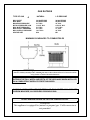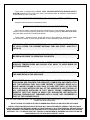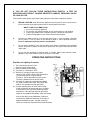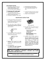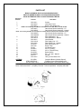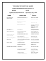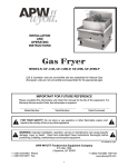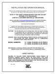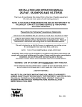
1
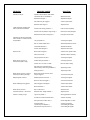
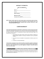
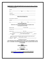
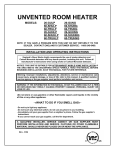
INSTALLER: Leave this manual with the appliance.
CONSUMER: Retain this manual for future reference.
UNVENTED ROOM HEATER
MODELS:
26-GULP
60-SHULP
60-TRULP
26-GUHLP
60-SHUHLP
60-TRUHLP
26-GUNG
60-SHUNG
60-TRUNG
26-GUHNG
60-SHUHNG
60-TRUHNG
INSTALLATION AND OPERATING INSTRUCTIONS
England’s Stove Works highly recommends the use of smoke detectors and
Carbon Monoxide detectors with any hearth product, including this unit. Follow all
manufacturer’s instructions when using smoke or Carbon Monoxide detectors.
This appliance may be installed in an aftermarket, permanently located, manufactured
(mobile home), where not prohibited by code.
This appliance is only for use with the type of gas indicated on the rating plate. This
appliance is not convertible for use with other gases.
Warning: Improper installations, adjustments, alterations, service or maintenance can
cause injury, property damage, or loss of life; refer to this manual. A qualified installer,
service agency or the gas supplier must perform installation and service.
WARNING: IF THE INFORMATION IN THIS MANUAL IS NOT FOLLOWED EXACTLY A FIRE
OR EXPLOSION MAY RESULT CAUSING PROPERTY DAMAGE, PERSONAL INJURY OR
LOSS OF LIFE.
•Do not store or use gasoline or other flammable vapors and liquids in the vicinity
of this or any other appliance.
A QUALIFIED INSTALLER, SERVICE AGENCY OR GAS SUPPLIER MUST
PERFORM INSTALLATION AND SERVICE. CLOTHING OR OTHER FLAMMABLE
MATERIAL SHOULD NEVER BE PLACED ON OR NEAR THE APPLIANCE.
→WHAT TO DO IF YOU SMELL GAS←
•Do not try to light any appliance.
•Do not touch any electrical switch; do not use any phone in your building.
•Immediately call your gas supplier from a neighbor’s phone. Follow the gas supplier’s
instructions.
•If you cannot reach your gas supplier, call the fire department.
This is an unvented gas-fired heater. It uses air (oxygen) from the room
in which it is installed. Provisions for adequate combustion and
ventilation air must be provided. Refer to Installation Instructions.
Rev. 10/08
A letter from our Technical Support department:
Thank you for purchasing this fine product from England’s Stove
Works!
England's Stove Works was started, and is still owned by, a family
that believes strongly in a "Do It Yourself" spirit – that’s one reason
you found this product at your favorite “Do It Yourself” store.
We intentionally design and build our stoves so that any homeowner
can maintain his or her unit with basic tools, and we're always more
than happy to show you how to do the job as easily and as
inexpensively as possible.
From our free, downloadable service sheets; to our Pellet Service
Video; to our new "wizard-style," click-through Troubleshooting
guide on our web site, we have always tried to help our customers
stay "heat-ready," especially when oil and electricity prices continue
to skyrocket.
Please look at our vast Help section on our web site and call our
Customer Service department at (800) 245-6489 if you need any help
with your unit. We are nearly always able to help “walk you through”
any repairs, problems or questions you may have.
PLEASE NOTE: While information obtained on our web site and
through our 800 number is always free of charge, there will be a
service charge incurred with any “on-site” repairs or maintenance
that we may arrange.
Wishing you years of efficient, quality and “comfy” heating,
England’s Stove Works
Technical Support Department
www.englanderstoves.com
(800) 245-6489
IF YOU HAVE A PROBLEM WITH THIS UNIT DO NOT RETURN IT TO THE DEALER.
CONTACT TECHNICAL SUPPORT at (800) 245-6489.
INSTALLATION INSTRUCTIONS
1. Minimum inlet gas supply pressure must be 5.5” w.c. for natural gas and 11” w.c. for
propane (LP) gas for the purpose of adjustment. Maximum gas supply pressure must
not exceed 10.5” w.c. with natural gas, or 14” w.c. with propane (LP) gas. Use the
correct gas type for your appliance — check the tag for gas type and do not convert
from one to the other. If you are using propane the tank must be located outdoors.
Warning: Connecting directly to an unregulated propane tank can cause an
explosion.
2. Make gas connection grate assembly with:
a) Black iron pipe with malleable iron fittings.
b) An AGA approved corrugated metal connector
(not to exceed two feet (2’) in length).
c) Copper pipe or tubing, if acceptable to the authority having
jurisdiction. Copper pipe must be tinned.
3. Turn on the gas supply and check for leaks. DO NOT USE AN OPEN FLAME. Use a
soap and water solution for this check.
4. For the correct log positioning refer to “SET ASSEMBLY” as described later in the
manual.
5. Installation and provisions for combustion and ventilation air must conform to local
codes or in their absence the National Fuel Gas Code – Z21.11.2-2007.
6. Keep the operating area clear and free of combustible materials, gasoline and other
flammable liquids and vapors.
7. The appliance and its individual shut off valve must be disconnected from the gas
supply piping system during any pressure testing of the gas supply piping system at
least equal to or less than ½ psig (3.5 kPa).
8. A one-eighth inch (1/8”) N.P.T. plugged tapping, accessible for test gauge
connection must be provided immediately upstream of the gas supply connection to
the appliance.
9. Never install appliance in: bedroom or bathroom, high traffic areas, recreational
vehicles, windy or drafty areas, or where curtains, furniture, clothing or flammable
objects are less than forty-two inches (42”) from the front of the appliance.
Important: The copper heat sensor attached to the valve should be placed outside and
to the rear of the stove for a more accurate room temperature reading.
Visit our web site at www.englandsstoveworks.com for helpful information, frequently
asked questions, parts and accessory orders and more.
Technical Problems: (800) 245-6489
Parts orders ONLY: (800) 516-3636
GAS RATINGS
TYPE OF GAS
→
MAX. INPUT
MIN. INPUT
MANIFOLD PRESSURE
M/FOLD PRESSURE LOW
MIN. INLET PRESSURE
MIN. SUPPLY PRESSURE
MAX. SUPPLY PRESSURE
ORIFICE SIZE
NATURAL
L.P./PROPANE
34,500 BTU/HR
20,000 BTU/HR
3.5” W.C.
1.0/3.5” W.C.
5.0” W.C.
5.5” W.C.
10.5” W.C.
#34
30,000 BTU/HR
20,000 BTU/HR
10” W.C.
4.5/10.0” W.C.
11.0” W.C.
11” W.C.
14” W.C.
#51
MINIMUM CLEARANCES TO COMBUSTIBLES
England’s Stove Works highly recommends the use of smoke detectors and Carbon Monoxide
detectors with any hearth product, including this unit. Follow all manufacturer’s instructions when
using smoke or Carbon Monoxide detectors.
THIS APPLIANCE SHALL BE INSTALLED ON A METAL OR WOOD PANEL THAT
EXTENDS THE FULL WIDTH AND DEPTH OF THE APPLIANCE WHEN INSTALLED
ON A COMBUSTIBLE SURFACE OTHER THAN WOOD.
WARNING: WHEN USED WITHOUT FRESH AIR THIS HEATER MAY GIVE OFF
CARBON MONOXIDE, AN ODORLESS POISONOUS GAS.
OPEN A WINDOW AN INCH OR TWO FOR COMBUSTION AIR.
WARNING
England’s Stove Works highly recommends the use of smoke detectors and Carbon Monoxide
This
appliance
ishearth
equipped
(natural
or propane)
gas. Fieldinstructions
conversion
detectors
with any
product,for
including
this unit.
Follow all manufacturer’s
when is
using smokenot
or Carbon
Monoxide
permitted
. detectors.
This heater is equipped with a PILOT LIGHT (OXYGEN DEPLETION SENSOR) SAFETY
SYSTEM designed to turn off the unit if there is not sufficient fresh air available. If the appliance
keeps shutting off, have it serviced.
DO NOT TAMPER WITH THE PILOT LIGHT (ODS) SAFETY SYSTEM!
Keep the burner and control compartment clean.
CARBON MONOXIDE POISONING MAY LEAD TO DEATH
Early signs of carbon monoxide poisoning resemble the flu, with headache, dizziness and/or
nausea; if you have these signs the heater may not be operating properly. Get fresh air at once!
Have the heater serviced by a qualified technician.
Some people – pregnant women, people with heart or lung disease or anemia, those under
the influence of alcohol, or those at high altitudes are more affected by carbon monoxide.
THE INSTALLATION MUST CONFORM TO LOCAL CODES OR, IN THE ABSENCE
OF LOCAL CODES, THE CURRENT NATIONAL FUEL GAS CODE – ANSI Z223.1
(NFPA 54).
ANY SAFETY SCREEN OR GUARD REMOVED FOR SERVICING THIS UNIT MUST
BE REPLACED PRIOR TO OPERATING THE HEATER.
CHILDREN AND ADULTS SHOULD BE ALERTED TO THE HAZARDS OF HIGH
SURFACE TEMPERATURES AND SHOULD STAY AWAY TO AVOID BURNS OR
CLOTHING IGNITION.
YOUNG CHILDREN SHOULD BE CAREFULLY SUPERVISED WHEN THEY ARE IN
THE SAME ROOM AS THE APPLIANCE.
THIS HEATER SHALL NOT BE INSTALLED IN A CONFINED SPACE UNLESS
PROVISIONS ARE PROVIDED FOR ADEQUATE COMBUSTION AND VENTILATION
AIR. THE NATIONAL FUEL GAS CODE DEFINES A CONFINED SPACE AS A
SPACE WHOSE VOLUME IS LESS THAN 50 CUBIC FEET PER 1,000 BTU PER
HOUR (4.8 CUBIC METERS PER KW) OF THE AGGREGATE INPUT RATING OF
ALL APPLIANCES INSTALLED IN THAT SPACE. ROOMS COMMUNICATING
DIRECTLY WITH THE SPACE IN WHICH THE APPLIANCES ARE INSTALLED
THROUGH OPENINGS NOT FURNISHED WITH A DOOR, ARE CONSIDERED A
PART OF THE CONFINED SPACE.
DUE TO HIGH TEMPERATURES, THE APPLIANCE SHOULD BE LOCATED OUT OF TRAFFIC AND AWAY FROM
FURNITURE AND DRAPERIES.
DO NOT PLACE CLOTHING OR OTHER FLAMMABLE MATERIAL ON OR NEAR THE APPLIANCE.
INSTALLATION AND REPAIR SHOULD BE DONE BY A QUALIFIED SERVICE PERSON. THE APPLIANCE
SHOULD BE INSPECTED BEFORE USE AND AT LEAST ANNUALLY BY A PROFESSIONAL SERVICE PERSON.
MORE FREQUENT CLEANING MAY BE REQUIRED DUE TO EXCESSIVE LINT FROM CARPETING, BEDDING
MATERIAL, ETC. IT IS IMPERATIVE THAT CONTROL COMPARTMENTS, BURNERS AND CIRCULATING AIR
PASSAGEWAYS OF THE APPLIANCE BE KEPT CLEAN.
“WARNING: If the area in which the heater may be operated is smaller than that
defined as an unconfined space or if the building is of unusually tight construction, provide
adequate combustion and ventilation air by one of the methods described in the National Fuel
Gas Code, ANSI Z223.1/NFPA 54, Air for Combustion and Ventilation, or applicable local
codes.”
“The National Fuel Gas Code, ANSI Z223.1/NFPA 54 defines a confined space as a space
whose volume is less than 50 ft3 per 1000 Btu/hr (4.8 m3 per kw) of the aggregate input
rating of all appliances installed in that space and an unconfined space as a space whose volume
is not less than 50 ft3 per 1000 Btu/hr (4.8 m3 per kw) of the aggregate input rating of all
appliances installed in that space. Rooms communicating directly with the space in which the
appliances are installed, through openings not furnished with doors, are considered a part of the
unconfined space.” For example, add the BTU for each gas appliance in the room and then
compare the size of the room to see if it will accept 1,000 BTU for each 50 cubic feet. The cubic
feet in the room can be calculated by multiplying the length by the width times the height of the
ceiling. If the room has 8-foot ceilings and is 11 feet by 15 feet, it would have 1,320 cubic feet
(8x11x15). You can now multiply by 1,000 and divide this cubic volume by 50 cubic feet/1,000
BTU and the result (1,320x1,000÷50) of 26,400 represents the accumulated BTU capacity for
this room size. If the result is greater than the accumulated BTU of all the appliances in the room,
then the room is an unconfined space and qualifies for installation of the unvented heater. If the
result is less than the accumulated BTU of all appliances in the room, then the room is a confined
space and the unvented heater should not be installed in this room.
The formula for this calculation: BTU/HT = L x W x H x 1,000
50
If the room has a door to an adjoining room, use only the dimensions to the room where the
heater will be located. If the room has an open area between two rooms the total length, width
and height can be used in your calculations.
LOG ASSEMBLY
IMPORTANT! The logs MUST be placed exactly as shown in the diagram. If there is any
evidence of carbon or blackening on the logs they may be incorrectly placed in the unit.
NOTE (Models manufactured prior to 3/00) – For removal of the screen you must:
1)
Lift up on the screen.
2)
Push the screen toward the logs,
past the clips.
3)
Push the screen down to the bottom
of the firebox.
4)
Pull the top of the screen forward
and up.
For models manufactured 3/00 and later, simply
remove the four Phillips Head screws to take out
the screen. Do not over-tighten the screws when
reinstalling.
WARNING: ANY CHANGE TO THIS HEATER OR ITS CONTROLS CAN BE DANGEROUS.
WARNING: Failure
position
the parts in
accordance
this diagram
or OR
failure
to use
MODIFICATIONS
TOtoTHIS
APPLIANCE
MAY
CAUSEwith
SERIOUS
INJURY
DEATH.
parts specifically
approved
with this heater may result in property damage or
ANYonly
CHANGES
WILL VOID
THE WARRANTY.
injury.
FOR YOUR SAFETY personal
- READ
BEFORE OPERATING
MODIFICATIONS TO THIS APPLIANCE MAY CAUSE SERIOUS INJURY OR
DEATH. ANY CHANGE WILL VOID THE WARRANTY.
WARNING: ANY CHANGE TO THIS HEATER OF ITS CONTROLS CAN BE
DANGEROUS.
IF YOU DO NOT FOLLOW THESE INSTRUCTIONS EXACTLY A FIRE OR
EXPLOSION MAY RESULT CAUSING PROPERTY DAMAGE, PERSONAL INJURY
OR LOSS OF LIFE.
This unit has a piezo ignition pilot. When lighting the pilot, follow these instructions exactly.
A.
BEFORE LIGHTING, smell around the appliance area for gas. Be sure to smell next to
the floor because some gas is heavier than air and will settle on the floor.
WHAT TO DO IF YOU SMELL GAS
1. Do not try to light any appliance.
2. Do not touch any electrical switch; do not use the phone in your building.
3. Call the gas supplier from a neighbor’s phone. Follow their instructions.
4. Call the fire department if you cannot reach the gas supplier.
B.
Use only your hand to push in or turn the gas control knob — never use tools. If the knob
will not push in or turn by hand, do not attempt to repair it. Call a qualified technician.
Force or attempted repair may result in an explosion.
C.
Do not use the appliance if any part has been under water. Immediately call a qualified
service technician to inspect the unit and to replace any of the gas control that has been
under water.
D.
Do not use this appliance for burning trash or cooking. Never place matches, paper,
garbage or any other material on top of the logs or in the flame.
OPERATING INSTRUCTIONS
Pilot Gas and Lighting Procedure
1) Turn off all electric power to unit.
Remove control access panel.
2) Set thermostat to lowest setting.
3) Turn knob “A” clockwise to “OFF”.
4) Wait five (5) minutes to clear out any gas.
Smell for gas –STOP—follow safety precautions
if you do smell gas (If not go to step 6).
Find pilot – follow metal tube from gas control.
The pilot is between the two burner tubes.
5) Turn knob “A” slightly counterclockwise towards
the “IGN” position until it stops. Press down and
hold for five seconds (only pilot gas flows).
6) Continue pressing knob “A” down while turning
further c/clockwise to activate the piezo. Continue
to hold down for ten (10) seconds after pilot light
has been lit. If the pilot light does not light, these
steps can be repeated immediately. (See note below)
Note: If pilot flame is not established, equipment
manufacturer (OEM) will determine the number of
additional attempts to light – and with continued
failure, the purge time required before further attempts.
MAIN BURNER IGNITION
1) Upon lighting, release knob and turn
further counterclockwise ← to “ON”
position (both pilot and gas flow).
2) Turn on all electric power to appliance.
3) Set thermostat to desired setting.
4) To turn off the gas to the main burner
only, turn gas control clockwise → to
pilot.
TO TURN GAS OFF TO APPLIANCE
1) Set thermostat to the lowest setting.
2) Turn off all electric power to the
appliance if service is to be performed.
3) Remove control access panel.
4) Turn knob “A” clockwise → until it stops.
5) Press down slightly and continue turning
clockwise → from pilot position to “OFF”.
6) Replace control access panel.
MAINTENANCE INSTRUCTIONS
1) Periodic visual checks of the pilot should
be conducted to ensure the flame is
present except when the valve control
knob is in the “OFF” position.
2) The pilot flame should always be
present when the heater is in operation,
and should just touch the top of the
thermocouple tip.
3) If the pilot flame does not touch the
thermocouple, then the main burner is
unlikely to function properly.
4) Remove the logs from the grate
assembly and vacuum any loose
particles from the grate and burner area
each month.
5) Flame Appearance
In normal operation at the full rate, after
15 minutes the flame appearance
should be observed (See diagram).
Flame Appearance
6) All components (see parts list) are
available directly through the factory.
Write or telephone:
England’s Stove Works, Inc.
Technical Support
P.O. Box 206
Monroe, VA 24574
(Parts Orders: 800-516-3636)
(FAX: 434-929-4810)
7) Installation and all repairs should be
done by a qualified service person. The
appliance should be inspected before
use and at least annually by a qualified
service person. It is imperative that
control compartments, burners and
circulating air passageways of the
appliance be kept clean. Note: More
frequent cleaning may be required
due to excessive lint from carpeting,
bedding material, etc.
WARNING: DO NOT ADJUST THE GAS ORIFICE. KEEP AREA CLEAR AND
FREE FROM COMBUSTIBLE MATERIALS, GASOLINE AND OTHER
FLAMMABLE VAPORS AND LIQUIDS.
WARNING: FAILURE TO KEEP THE PRIMARY AIR OPENING(S) OF THE BURNER
CLEAN MAY RESULT IN SOOTING AND PROPERTY DAMAGE.
PARTS LIST
Model 26-GUNG/26-GULP and 26-GUHNG/26-GUHLP
Model 60-SHUNG/60-SHULP and 60-SHUHNG/60-SHUHLP
Model 60-TRUNG/60-TRULP and 60-TRUHNG/60-TRUHLP
Exploded
View No.
Part No.*
1
2
3
GUV-3211
GUV-3033
GUV-3053
Part Name*
Screen
Valve Door Cover
Burner Tube Supply Line
NOTE: The following Valve/Burner assemblies are for GU, SHU and TRU models
4
GUV-30LP
GUV-30NG
Gas Valve & Burner Assembly – LP
Gas Valve & Burner Assembly – Natural
NOTE: The following Valve/Burner assemblies are for GUH, SHUH and TRUH (Hearth-adaptable models)
5
6
7
8
9
10
11
12
13
14
15
16
OPTIONS:
GUV-30HLP
GUV-30HNG
GUV-12741
GUV-50741
GUV-3012
GUV-31612
GUV-3166
GU-3053
GUV-100
GU-38
GU-3812
GU-3814
GU-LP051
GU-NG034
GUV-L1
GUV-3215
Gas Valve & Burner Assembly – LP
Gas Valve & Burner Assembly – Natural
Pilot and Bracket – LP
Pilot and Bracket – Natural
Valve Bracket
Pilot Supply Line – LP
Pilot Supply Line – Natural
Main Gas Supply Line
Burner Tube
3/8” Brass Fitting
3/8” x ½” Fitting
3/8” x ¼” Brass Fitting
Burner Orifice
#51 – LP; #34 – Natural
Log Set
Two (2) Piece Brass Trim
AC-26BA
Complete Blower (Variable Speed)
STB-UV/SHTB-UV
Fireplace Cover (Hearth Model only)
AC-104-G/SH-104-G
Brass Backplate Trim (Hearth Model only)
*Note: Only one of each part is required per stove.
*Note: Parts orders ONLY: call (800) 516-3636. Technical problems: call (800) 245-6489.
TROUBLE SHOOTING GUIDE
ITEMS IN THIS GUIDE MARKED WITH AN ASTERISK (*) SHOULD ONLY BE
PERFORMED BY A LICENSED GAS FITTER OR EQUIVALENT.
WARNING
CAUTION
Turn off and let the unit cool before servicing.
Only a qualified service person should
service or repair this unit.
PROBLEM
When ignitor is pressed
there is no ODS pilot.
Never use a wire, needle, or similar
object to clean the ODS pilot.
This can damage the pilot.
POSSIBLE CAUSE
SOLUTION
Ignitor electrode positioned wrong. →
*Replace ignitor electrode.
Ignitor electrode broken. →
*Replace ignitor electrode.
Ignitor electrode not connected
to ignitor cable. →
*Replace ignitor cable.
Ignitor cable pinched or wet. →
*Free ignitor cable if pinched
by any metal or tubing. Keep
ignitor cable dry.
Replace cable if spark still
isn’t there after freeing the
pinched wire.
Flame seems to blow out
or will not light.
Air in the gas line.→
Purge air from line (Check to
ensure gas is going to pilot.)
Appliance produces odors.
Stove burning vapors from paint,
hair spray, glue, etc.→
Ventilate room. Stop using
products while operating unit.
Gas leak. See warning label on cover.→
*Locate and correct all leaks.
Gas leak. See warning label on cover.→
*Locate and correct all leaks.
Control valve defective.→
*Replace control valve.
Smoke or odor during initial burn.
Vapors from paint or production process.→
Unit curing out. Will stop.
Strong gas smell.
LP fuel may have additives or be poor quality.→
*Shut off gas. Check supplier.
Excess gas pressure.→
*Call utility company/installer.
Logs may be out of place.→
Compare placement of logs to
the diagram in the manual.
Orifice size may be incorrect.→
Replace if incorrect.
Gas supply turned off or manual shutoff
valve is closed.→
Turn on gas or open supply.
Control knob not in “PILOT” position.→
Correct knob position.
Air in gas line when installed.→
Purge air from system by
holding down control knob.
Repeat ignition.
“ODS” pilot is clogged.→
Gas regulator setting is incorrect.→
*Replace “ODS” assembly.
*Replace gas regulator.
Gas odor even when control
knob is in “OFF” position.
Gas smell – sooting.
When ignitor button is pressed,
there is spark at ODS and no ignition.
PROBLEM
Pilot will not stay lit.
POSSIBLE CAUSE
SOLUTION
Altitude is above 4000 ft.; ODS sensor
requirement for air not satisfied.→
Altitude is too high.
Defective thermopile.→
*Replace thermopile.
Pilot orifice may be clogged.→
*Clean out pilot orifice.
Defective valve magnet.→
*Replace valve.
Control knob not fully pressed in.→
Press in knob completely.
Control knob not pressed in long enough.→
Hold 30 sec. after pilot lights.
Manual shut-off valve not fully open.→
Fully open shut-off valve.
Low gas pressure.→
*Contact gas supplier.
Dirty or clogged “ODS” pilot.→
*Replace assembly or service.
Thermopile damaged.→
*Replace thermopile.
Control valve damaged.→
*Replace control valve.
Burner orifice clogged.→
*Clean burner; replace orifice.
Orifice is too small.→
*Replace orifice if necessary.
Inlet gas pressure too low.→
*Contact gas supplier.
Problem with gas pressure.→
*Check gas pressure.
Control not on or is set on “LOW”.
Move to “HIGH” setting.
Gas valve may be clogged due to
debris entering valve during installation.→
*Replace gas valve.
Faulty gas valve.→
*Replace gas valve.
Burner will not come on or has an
extremely low flame (pilot okay).
Burner ports and/or carryover ports
may be clogged.→
*Check and clean ports.
Delayed ignition of burner.
Manifold pressure is too low.→
*Contact gas supplier.
Burner or orifice is clogged.→
*Check and clean both.
Orifice clogged or damaged.→
*Clean and/or replace.
Burner damaged.→
*Clean and/or replace.
Burner will not come on.
Dirt on valve seal.→
*Replace valve.
Control knob frozen – will not turn.
Defective valve; foreign material.→
*Replace valve.
Carbon or sooting on logs.
Logs out of position.→
See log placement in manual.
Air holes on burner tube obstructed.→
*Clean if necessary.
Gas type does not match stove.→
Check designation on valve.
Oversized orifice.→
LP fuel may have additives.→
Gas pressure may be incorrect.→
*Change if necessary.
*Check with gas supplier.
*Check with gas supplier.
“ODS” pilot lights, but flame dies
when control knob is released.
Pilot flame not touching thermopile,
which causes it to cool and shut off
the pilot flame.
Flame too low.
Burner will not come on or
has low flame (pilot is okay).
Burner backfiring during ignition.
WARRANTY INFORMATION
♦KEEP THIS WARRANTY♦
Model #__________________________________
Serial #__________________________________
Date Purchased ___________________________
Manufacture Date _________________________
Purchased From (Dealer) ____________________
NOTE: Always specify model and serial numbers when communicating with the factory.
We reserve the right to amend these specifications at any time without notice. The
only warranty applicable is our standard written warranty. We make no other
warranty, expressed or implied.
LIMITED WARRANTY
This unvented gas heater firebox is warranted for a period of five (5) years; the logs, valve, burner
and all other components for a period of one (1) year from the date of purchase against defects in
material or workmanship. This warranty covers only the cost of defective parts and applies only to
the original consumer purchaser. The replacement of defective parts will be without charge. This
warranty does not extend to:
1. Heater damage by accident, neglect, misuse, abuse, alteration, negligence of
others, improper installation, including the installation thereof by unqualified
installers.
2. The costs of removal, reinstallation or transportation of defective parts on the
heater.
3. Incidental or consequential damage.
This warranty is expressly in lieu of other warranties, expressed or implied, including the
warranty of merchantability of fitness for purpose and of all other liabilities, England Stove
Works, Inc. does not assume for it, any other obligation or liability in connection with the
sale or use of this heater.
A QUALIFIED INSTALLER in accordance with the instructions furnished with the unit MUST
INSTALL the heater. The defective heater should be returned at your expense to the dealer from
whom the product was purchased or an authorized service agent. Any products presented for
warranty repair must be accompanied by a dated proof of purchase. Since some states do not allow the
exclusion on limitation of incidental or consequential damage, or on how long an implied warranty lasts, the
above limitations may not apply to you.
WARRANTY REGISTRATION for England’s Stove Works
Purchased by (Name) ______________________________________________
Address _________________________________________________________
City ________________________ State __________ Zip _________________
Telephone _______________________________________________________
Email Address ___________________________________________________
DEALER INFORMATION
Purchased From (Dealer) ___________________________________________
Address _________________________________________________________
City ________________________ State __________ Zip _________________
UNIT INFORMATION –
(Please be sure to refer to sticker on back of manual or box
to complete this section)
Model Number _____________________ Purchase Date _________________
Purchase Price ____________________
Serial Number _____________________ Mfg. Date ______________________
How did you first hear about our product? (please check one)
___ Word of Mouth
___ Burn Trailer Demonstration
___ Internet
Other: ____________________________________________________
Where did you receive information about our product? (please check one)
___ Rec’d. info. via phone ___ Dealer (Name of dealer): ______________________
___ Internet
Other: _________________________________________________
IMPORTANT NOTICE
THIS REGISTRATION INFORMATION MUST BE ON FILE FOR THIS WARRANTY TO BE
VALID. PLEASE MAIL THIS INFORMATION WITHIN THIRTY (30) DAYS FROM THE DATE
OF PURCHASE.
Mail To:
England’s Stove Works, Inc.
Customer Service Department
P.O. Box 206
Monroe, VA 24574
Or, Fax To:
(434) 929-4810 – 24 hours a day
Or, now available – Go online to complete your Warranty Registration!
Visit www.englandsstoveworks.com if you prefer to register online.